EP3440293B1 - Système de cales de fermeture pour accoupler de façon amovible une porte de véhicule à un élément structurel d'une carrosserie de véhicule - Google Patents
Système de cales de fermeture pour accoupler de façon amovible une porte de véhicule à un élément structurel d'une carrosserie de véhicule Download PDFInfo
- Publication number
- EP3440293B1 EP3440293B1 EP17716125.4A EP17716125A EP3440293B1 EP 3440293 B1 EP3440293 B1 EP 3440293B1 EP 17716125 A EP17716125 A EP 17716125A EP 3440293 B1 EP3440293 B1 EP 3440293B1
- Authority
- EP
- European Patent Office
- Prior art keywords
- wedge
- locking
- module
- displacement unit
- retaining
- Prior art date
- Legal status (The legal status is an assumption and is not a legal conclusion. Google has not performed a legal analysis and makes no representation as to the accuracy of the status listed.)
- Active
Links
Images


Classifications
-
- E—FIXED CONSTRUCTIONS
- E05—LOCKS; KEYS; WINDOW OR DOOR FITTINGS; SAFES
- E05B—LOCKS; ACCESSORIES THEREFOR; HANDCUFFS
- E05B85/00—Details of vehicle locks not provided for in groups E05B77/00 - E05B83/00
- E05B85/04—Strikers
-
- E—FIXED CONSTRUCTIONS
- E05—LOCKS; KEYS; WINDOW OR DOOR FITTINGS; SAFES
- E05B—LOCKS; ACCESSORIES THEREFOR; HANDCUFFS
- E05B15/00—Other details of locks; Parts for engagement by bolts of fastening devices
- E05B15/0006—Devices for aligning wing and frame; Anti-rattling devices
-
- E—FIXED CONSTRUCTIONS
- E05—LOCKS; KEYS; WINDOW OR DOOR FITTINGS; SAFES
- E05B—LOCKS; ACCESSORIES THEREFOR; HANDCUFFS
- E05B15/00—Other details of locks; Parts for engagement by bolts of fastening devices
- E05B15/02—Striking-plates; Keepers; Bolt staples; Escutcheons
- E05B15/0205—Striking-plates, keepers, staples
- E05B15/029—Closures, e.g. preventing dirt or paint from entering into the striker
-
- E—FIXED CONSTRUCTIONS
- E05—LOCKS; KEYS; WINDOW OR DOOR FITTINGS; SAFES
- E05B—LOCKS; ACCESSORIES THEREFOR; HANDCUFFS
- E05B85/00—Details of vehicle locks not provided for in groups E05B77/00 - E05B83/00
- E05B85/20—Bolts or detents
- E05B85/22—Rectilinearly moving bolts
-
- E—FIXED CONSTRUCTIONS
- E05—LOCKS; KEYS; WINDOW OR DOOR FITTINGS; SAFES
- E05B—LOCKS; ACCESSORIES THEREFOR; HANDCUFFS
- E05B63/00—Locks or fastenings with special structural characteristics
- E05B63/14—Arrangement of several locks or locks with several bolts, e.g. arranged one behind the other
-
- E—FIXED CONSTRUCTIONS
- E05—LOCKS; KEYS; WINDOW OR DOOR FITTINGS; SAFES
- E05B—LOCKS; ACCESSORIES THEREFOR; HANDCUFFS
- E05B77/00—Vehicle locks characterised by special functions or purposes
- E05B77/34—Protection against weather or dirt, e.g. against water ingress
-
- E—FIXED CONSTRUCTIONS
- E05—LOCKS; KEYS; WINDOW OR DOOR FITTINGS; SAFES
- E05B—LOCKS; ACCESSORIES THEREFOR; HANDCUFFS
- E05B81/00—Power-actuated vehicle locks
- E05B81/12—Power-actuated vehicle locks characterised by the function or purpose of the powered actuators
- E05B81/20—Power-actuated vehicle locks characterised by the function or purpose of the powered actuators for assisting final closing or for initiating opening
Definitions
- the invention relates to a closing wedge system for the detachable coupling of a vehicle flap with a structural part of a vehicle body according to the preamble of patent claim 1.
- a generic closing wedge system is from the DE 10 2012 011 420 A1 known.
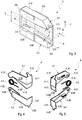
- FIG. 1 shown and from the DE 10 2012 011 420 A1 known Sch spakeilsystem 1 of a vehicle for releasably connecting a vehicle door 11 of a vehicle body 10 with its side wall frame 12 as a vehicle structural part comprises a parallel with two mutually slidably mounted locking wedges 2.1 and 2.2 formed with wedge surfaces lock wedge 2 and cooperating with this closing jaw module 3, wherein in the coupled state of Lock wedge system 1 via adjacent wedge surfaces the locking wedge module 2 and the holding jaw module 3 are coupled without play.
- the holding jaw module 3 is formed with two, the closing jaw module 2 receiving retaining jaws between 3.1 and 3.2 with wedge-shaped splines 3.11 and 3.21, so that by means of a motor drive device, the strikers 2.1 and 2.2 by dislocation with their wedge surfaces in the keyways 3.11 and 3.21 under investment be pressed at the wedge surfaces and thereby an effective form and adhesion of the two locking wedges 2.1 and 2.2 with the holding jaws 3.1 and 3.2 is achieved.
- Another embodiment of the holding jaw module according to this DE 10 2012 011 420 A1 provides that, for facilitated insertion of the locking wedges between the holding jaws these are pivoted ⁇ at an angle relative to a horizontal center line, so that the two keyways taper conically. At this conical course of these two splines and the side edges of the two locking wedges are adjusted.
- Such a displacement unit of a closing wedge system is also known from DE 10 2012 025 392 B3 known, which is designed as a flat cover with a flange with adapted to the wedge shape of the keyways of the holding jaws noses to cover also provided for introducing the striker module Ein Industriesstirnseite the holding jaw module.
- the DE 10 2012 025 336 A1 describes a vehicle lock device, in which the from DE 10 2012 011 420 A1 known coupling device in addition to the function of coupling the vehicle door with a body pillar also performs the function of a vehicle lock, so that is dispensable on a conventional vehicle lock.
- a coupling device known which is used as a so-called power joint for releasably connecting a vehicle door with a door pillar.
- This vehicle door is hinged stop side with a power joint on the local door pillar and has a the power joint with the power lock connecting Mataussteifung so that forces from the door pillars on the power and the power steering can be introduced into the vehicle door and thereby the rigidity of the vehicle body is increased.
- the starting slope of the holding jaw is compensated. If the vehicle door is closed as a vehicle flap, the closing wedge module is introduced into the holding jaw module for this purpose and at the same time the displacement unit is moved from the closed position in the direction of the vehicle interior between the guide rails into the open position. Since the holding jaws at the Ein Industriesstirnseite of the holding jaw module have a greater distance than the vehicle interior facing end side, the displacement unit is pushed together like a fan overlapping. Conversely, the vehicle door is opened, so the Latching module led out of the holding jaw module, the displacement unit is moved from lying between the guide rails open position in the closed position between the holding jaws and fanned out again, so that the holding jaws are bridged.
- the two lamellar elements biasing in Auffamba mecanicscardi spring element is formed as arranged on the pivot axis leg spring whose ends are each supported against a lamella element of the displacement unit.
- the starting slope of the holding jaw is compensated and fulfills the same function as the displacement unit described above.
- a tension spring is used, which simultaneously connects the two plate elements.
- the spring element is designed as an omega spring. With such an omega spring, the two lamellar elements are connected simultaneously.
- the starting slope of the holding jaw is compensated and fulfills the same function as the displacement unit described above.
- the difference from the above-described displacement unit lies in the fact that the two lamellar elements are connected by means of an elastic central element which, in the closed position, presses apart the two lamellar elements, so that these rest against the holding jaws. By moving into the open position, the two lamellar elements are compressed due to the elasticity of the central element.
- a one-piece displacement unit can be created with an elastic central element.
- a spring element is arranged in the region of the guide rails, with which the displacement unit is biased in the direction of the closure position. With such a spring element ensures that the displacement unit remains in its closed position. The displacement unit is moved against the spring force of this spring element in its open position.
- a last advantageous development of the invention provides that the lamellar elements cover with an end face of the holding jaw module Flanges are formed with adapted to the wedge shape of the keyways lugs. This ensures that the Ein Industriesstirnseite the holding jaw module is covered with the vehicle door open and gives an optimal design impression.
- FIG. 1 illustrated and known closing wedge system 1 represents a coupling device, with which - as described above - by means of a striker module 2 and a holding jaw module 3, a vehicle door 11 is coupled to a side wall frame 12 of a vehicle body 10.
- a coupling device is usually in addition a conventional vehicle lock (in FIG. 1 not shown), this coupling device leads to a stiffening of the vehicle body 10.
- FIG. 2 show a lock wedge module 2 and a holding jaw module 3 of a locking wedge system 1 according to the invention.
- a closing wedge holder 2.3 of the striker module 2 on opposite sides in the vertical direction R (z-direction) to a symmetry axis S each have a closing wedge 2.1 and 2.2 slidably disposed.
- These two closing wedges 2.1 and 2.2 have corresponding wedge surfaces to form a wedge edge 2.10 and 2.20.
- FIG. 3 comprises the holding jaw module 3 two spaced apart on a base plate 3.5 holding jaws 3.1 and 3.2, each with a keyway 3.11 and 3.21.
- the striker module 2 is introduced via an insertion end 3.3 of the holding jaw module 3 in the insertion direction E, so that the striker module 2 is located between the two holding jaws 3.1 and 3.2.
- the two locking wedges 2.1 and 2.2 are extended in opposite directions R (z-direction) from a non-coupling position in a coupling position, whereby the two locking wedges 2.1 and 2.2 with their end-side wedge surfaces in each of the adapted to the contour of these wedge surfaces keyways 3.11 and 3.21 are pressed and thus a non-positive and positive connection between the locking wedge module 2 and the holding jaw module 3 is produced.
- the wedges 2.1 and 2.2 of the striker module 2 are not aligned parallel to each other, more precisely, the wedge edges 2.10 and 2.20 of these strikers 2.1 and 2.2 are not parallel to the axis of symmetry S of the striker module 2, but extend in the insertion direction E obliquely toward each other.
- the wedge edge 2.10 of the closing wedge 2.1 and the wedge edge 2.20 of the closing wedge 2.2 each have an inclination angle ⁇ with the axis of symmetry S. This means that the end-side distance a of the two wedge edges 2.10 and 2.20 at the insertion-side end 2.4 of the striker module 2 is smaller than that Distance A at the opposite end 2.5.
- locking wedges 2.1 and 2.2 are also the splines 3.11 and 3.21 of the two holding jaws 3.1 and 3.2 running obliquely to the axis of symmetry S of the striker module 3 running.
- the holding jaw surface 3.12 receiving the keyway 3.12 has an inclination angle ⁇ relative to the symmetry axis S and the holding jaw surface 3.22 receiving the keyway 3.21 also has an inclination angle ⁇ with respect to the symmetry axis S, wherein the distance B of these two holding jaw surfaces 3.12 and 3.22 at the insertion end side 3.3 is greater than the distance b at the opposite end of the two holding jaws 3.1 and 3.2.
- a displacement unit 4 between a closure position between the two holding jaws 3.1 and 3.2 and a space between the two holding jaws 3.1 and 3.2 releasing open position between the guide rails 3.10 and 3.20 displaceable. Therefore, the holding jaw surfaces 3.12 and 3.22 of the holding jaws 3.1 and 3.2 together with the adjoining end faces of the two guide rails 3.10 and 3.20 form a uniform surface.
- the two guide rails 3.10 and 3.20 are frontally and frontally covered by an angle-shaped cover plate 3.6, wherein on the front side of a spring element 3.4 is arranged, the function will be explained below.
- a displacement unit 4 in different embodiments will be described below with reference to FIGS. 4 to 14 described.
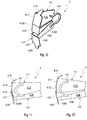
- the displacement unit 4 consists of a first strip-shaped thin plate element 4.1, a second strip-shaped thin plate element 4.2 and a leg spring as a spring element 4.3.
- Each of the lamellar elements 4.1 and 4.2 is L-shaped with a strip-shaped element 4.10 or 4.20 as a long leg of the L-shape and one of the strip-shaped element 4.10 or 4.20 at right angles projecting flange 4.11 or 4.21 designed as a short leg of the L-shape ,
- a circular connecting flange 4.13 with a short pivot axis 4.14 via which the two plate elements 4.1 and 4.2 are pivotally connected to each other.
- the first lamellar element 4.1 also has an outgoing from the connecting flange 4.13 and widening cone-shaped overlap region 4.12, which is delimited by means of a running into the flange 4.11 shoulder 4.120 with a thickness of the second fin element 4.2 corresponding shoulder height.
- this overlap area is 4.12 fan-like overlapped by the second blade element 4.2. If this overlapping area 4.12 is completely overlapped by the second lamella element 4.2, its side edge rests directly against the shoulder 4.120 and defines the open position of the displacement unit 4 in which it follows FIG. 9 located between the guide rails 3.10 and 3.20.
- FIG. 8 the free edge of the overlap region 4.12 at a running on the back of the second fin element 4.2 4.220 shoulder, which also has an overlap 4.22 of the second fin element 4.2 according to FIG. 5 Are defined.
- the leg spring is arranged as a spring element 4.3 on the pivot axis 4.14, wherein the ends are each fixed in a holding 4.16 of the first fin element 4.1 and in a holding 4.26 of the second fin element 4.2 such that the two fin elements 4.1 and 4.2 are pivoted against each other, so are biased in Auffambatationscardi D1 and D2.
- the closing wedge module 2 is clamped between the two holding jaws 3.1 and 3.2.
- the striker module 2 is extended from the holding jaw module 3, whereby the displacement unit 4 pushed from its open position between the guide rails 3.10 and 3.20 by a prestressed spring element 3.4 forward in the direction of Ein Industriesstirnseite 3.3 becomes.
- the closing unit 4 is fanned out due to the spring bias of the spring element 4.3, ie the two lamellar elements 4.1 and 4.2 are fanned out in their Auff kau ceremoniesscardi D1 or D2 until the outer edges positively abut positively against the holding jaw surfaces 3.12 and 3.22 of the two holding jaws 3.1 and 3.2 , wherein also on the flanges 4.11 and 4.21 together with their lugs 4.15 and 4.25 a positive connection of the holding jaws 3.1 and 3.2 is achieved at the Ein slaughterstirnseite 3.3 of the holding jaw module 3, as in FIG. 7 is shown.
- the striker module 2 is inserted via the insertion end 3.3 of the holding jaw module 3 between the holding jaws 3.1 and 3.2 while the displacement unit 4 against the spring force of the spring element 3.4 in the area of the guide rails 3.10 and 3.20 moved until this is in accordance with their open position FIG. 9 reached.
- the two plate elements 4.1 and 4.2 are compressed due to the oblique holding jaw surfaces 3.12 and 3.22 of the two holding jaws 3.1 and 3.2 until the overlap areas 4.12 and 4.23 are completely overlapped and therefore in the front view according to FIG. 9 only the shoulder 4.120 is visible.
- the displacement unit has 4 according to the FIGS. 4 and 5 of course, the same structure.
- FIG. 10 shows an alternative embodiment of the displacement unit 4.
- This displacement unit 4 according to FIG. 10 differs from the one according to the FIGS. 4 and 5 in that, instead of a leg spring as the spring element 4.3, an omega spring is provided. Otherwise, the structure of this displacement unit 4 corresponds to FIG. 10 the one according to the FIGS. 4 and 5 ,
- This displacement unit 4 also comprises a first plate element 4.1 and a second plate element 4.2.
- the omega spring as the spring element 4.3 connects the two plate elements 4.1 and 4.2, characterized in that one leg of the omega spring frictionally with the first fin element 4.1 and the other leg of the omega spring are positively connected to the second fin element 4.2.
- the two blade elements 4.1 and 4.2 are biased by means of this omega spring in Auff kau ceremoniesscardi, so that these blade elements 4.1 and 4.2 both in the open position according to FIG. 9 as well as in the closed position according to FIG. 3 pressed against the guide rails 3.10 and 3.20 or to the holding jaws 3.1 and 3.2.
- the first plate element 4.1 and the second plate element 4.2 each have no connecting flange 4.13 or 4.23 with associated pivot axis 4.14 or 4.24 axis opening and no holding 4.16 or 4.26.
- FIGS. 11 and 12 show a further alternative embodiment of a displacement unit 4, wherein instead of the omega spring of the displacement unit 4 after FIG. 10 an arcuate tension spring is used as the spring element 4.3.
- This spring element 4.3 connects the two fin elements 4.1 and 4.2 in the region of the flanges 4.11 and 4.21, wherein the convex Side of the tension spring in the direction of the flanges 4.11 and 4.21 shows.
- the connection of the two plate elements 4.1 and 4.2 is carried out to produce a direction of the fanning direction in D1 and D2 directed spring preload.
- the two blade elements 4.1 and 4.2 according to their structure that of the displacement unit 4 according to FIG. 10 ,
- the FIG. 11 shows the displacement unit 4 in its open position as shown FIG. 9 and the representation after FIG. 12 corresponds to the closing position according to FIG. 4 ,
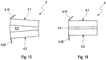
- FIGS. 13 and 14 show a last alternative embodiment of a displacement unit 4, which also includes a first fin elements 4.1 and a second fin elements 4.2, but which are cuboid with a thickness of the locking wedges 3.1 and 3.2 and the thickness of the guide rails 3.10 and 3.20 example.
- a displacement unit 4 also includes a first fin elements 4.1 and a second fin elements 4.2, but which are cuboid with a thickness of the locking wedges 3.1 and 3.2 and the thickness of the guide rails 3.10 and 3.20 example.
- the two lamellar elements 4.1 and 4.2 are connected by means of an elastic middle element 4.4 made of a plastic material form-locking and surface-locking in such a way that in the closed position of the sliding element 4 according to FIG. 13 due to the elastic property of the middle element 4.4, the two plate elements 4.1 and 4.2 pressed apart and pressed against the holding jaws 3.1 and 3.2 of the holding jaw module 3. If this displacement unit 4 is pushed out of this closure position into the open position between the guide rails 3.10 and 3.20, the two lamellar elements 4.1 and 4.2 due to the obliquely extending holding jaw surfaces 3.12 and 3.22 using the elastic property of the central element 4.4 in the closed position according to FIG. 14 pressed together.
- an elastic middle element 4.4 made of a plastic material form-locking and surface-locking in such a way that in the closed position of the sliding element 4 according to FIG. 13 due to the elastic property of the middle element 4.4, the two plate elements 4.1 and 4.2 pressed apart and pressed against the
Claims (7)
- Système de clavette de serrage (1) destiné à coupler de manière amovible une portière de véhicule (11) avec une partie de structure (12) d'une carrosserie de véhicule, comprenant- un module à clavettes de serrage (2) avec deux clavettes de serrage (2.1, 2.2) montées de manière à pouvoir coulisser l'une par rapport à l'autre dans le sens vertical (R) par rapport à un axe de symétrie (S) et munies respectivement d'un bord de clavette (2.10, 2.20) et d'un support de clavettes de serrage (2.3) destiné à recevoir de manière coulissante les clavettes de serrage (2.1, 2.2) et- un module à mâchoires de retenue (3) avec deux mâchoires de retenue (3.1, 3.2) recevant entre elles le module à clavettes de serrage (2) et munies respectivement d'une rainure de clavette (3.11, 3.21), dans lequel une fermeture par friction est créée entre les clavettes de serrage (2.1, 2.2) et les mâchoires de retenue (3.1, 3.2) par éloignement réciproque des clavettes de serrage (2.1, 2.2), dans lequel- un bord de clavette (2.10, 2.20) d'au moins une clavette de serrage (2.1, 2.2) ainsi que la rainure de clavette (3.11, 3.21), recevant ledit bord de clavette (2.10, 2.20), d'une mâchoire de retenue (3.1, 3.2) sont réalisés inclinés par rapport à l'axe de symétrie (S) des clavettes de serrage (2.1, 2.2) et des mâchoires de retenue (3.1, 3.2),caractérisé en ce que- le module à mâchoires de retenue (3) est réalisé avec des rails de guidage (3.10, 3.20) destinés à guider une unité de coulissement (4) entre une position de verrouillage faisant intervenir les mâchoires de retenue (3.1, 3.2) et une position d'ouverture faisant intervenir les rails de guidage (3.10, 3.20) et autorisant la réception du module à clavettes de serrage (2),- l'unité de coulissement (4) est formée d'au moins deux éléments lamellaires (4.1, 4.2) en forme de bande qui sont reliés de manière à se recouvrir à la manière d'un éventail et de manière à pivoter l'un par rapport à l'autre au moyen d'un axe de pivotement (4.14) agencé au niveau d'une extrémité des éléments lamellaires (4.1, 4.2), et- l'unité de coulissement (4) est formée d'un élément formant ressort (4.3) avec lequel les éléments lamellaires (4.1, 4.2) sont déployés à la manière d'un éventail lors d'un coulissement à partir de la position d'ouverture entre les rails de guidage (3.10, 3.20) jusque dans la position de verrouillage entre les mâchoires de retenue (3.1, 3.2).
- Système de clavette de serrage (1) selon la revendication 1,
caractérisé en ce que l'élément formant ressort (4.3) est réalisé sous la forme d'un ressort à branche agencé sur l'axe de pivotement (4.14) et dont les extrémités s'appuient respectivement contre un élément lamellaire (4.1, 4.2) de l'unité de coulissement (4). - Système de clavette de serrage (1) destiné à coupler de manière amovible une portière de véhicule (11) à une partie de structure (12) d'une carrosserie de véhicule, comprenant- un module à clavettes de serrage (2) avec deux clavettes de serrage (2.1, 2.2) montées de manière à pouvoir coulisser l'une par rapport à l'autre dans le sens vertical (R) par rapport à un axe de symétrie (S) et munies respectivement d'un bord de clavette (2.10, 2.20) et d'un support de clavettes de serrage (2.3) destiné à recevoir de manière coulissante les clavettes de serrage (2.1, 2.2), et- un module à mâchoires de retenue (3) avec deux mâchoires de retenue (3.1, 3.2) recevant entre elles le module à clavettes de serrage (2) et munies respectivement d'une rainure de clavette (3.11, 3.21), dans lequel une fermeture par friction est créée entre les clavettes de serrage (2.1, 2.2) et les mâchoires de retenue (3.1, 3.2) par éloignement réciproque des clavettes de serrage (2.1, 2.2), dans lequel- un bord de clavette (2.10, 2.20) d'au moins une clavette de serrage (2.1, 2.2) ainsi que la rainure de clavette (3.11, 3.21), recevant ledit bord de clavette (2.10, 2.20), d'une mâchoire de retenue (3.1, 3.2) sont réalisés inclinés par rapport à l'axe de symétrie (S) des clavettes de serrage (2.1, 2.2) et des mâchoires de retenue (3.1, 3.2),caractérisé en ce que- le module à mâchoires de retenue (3) est réalisé avec des rails de guidage (3.10, 3.20) destinés à guider une unité de coulissement (4) entre une position de verrouillage faisant intervenir les mâchoires de retenue (3.1, 3.2) et une position d'ouverture faisant intervenir les rails de guidage (3.10, 3.20) et autorisant la réception du module à clavettes de serrage (2), et- l'unité de coulissement (4) est formée d'au moins deux éléments lamellaires (4.1, 4.2) en forme de bande qui sont reliés de manière à se recouvrir à la manière d'un éventail et de manière à pivoter l'un par rapport à l'autre au moyen d'un ressort de traction agencé au niveau d'une extrémité des éléments lamellaires (4.1, 4.2) en tant qu'élément formant ressort (4.3), dans lequel les éléments lamellaires (4.1, 4.2) sont déployés à la manière d'un éventail lors d'un coulissement à partir de la position d'ouverture entre les rails de guidage (3.10, 3.20) jusque dans la position fermée entre les mâchoires de retenue (3.1, 3.2).
- Système de clavette de serrage (1) selon la revendication 3,
caractérisé en ce que l'élément formant ressort (4.3) est réalisé sous la forme d'un ressort en fil en forme de lettre oméga. - Système de clavette de serrage (1) destiné à coupler de manière amovible une portière de véhicule (11) à une partie de structure (12) d'une carrosserie de véhicule, comprenant- un module à clavettes de serrage (2) avec deux clavettes de serrage (2.1, 2.2) montées de manière à pouvoir coulisser l'une par rapport à l'autre dans le sens vertical (R) par rapport à un axe de symétrie (S) et munies respectivement d'un bord de clavette (2.10, 2.20) et d'un support de clavettes de serrage (2.3) destiné à recevoir de manière coulissante les clavettes de serrage (2.1, 2.2) et- un module à mâchoires de retenue (3) avec deux mâchoires de retenue (3.1, 3.2) recevant entre elles le module à clavettes de serrage (2) et munies respectivement d'une rainure de clavette (3.11, 3.21), dans lequel une fermeture par friction est créée entre les clavettes de serrage (2.1, 2.2) et les mâchoires de retenue (3.1, 3.2) par éloignement réciproque des clavettes de serrage (2.1, 2.2), dans lequel- un bord de clavette (2.10, 2.20) d'au moins une clavette de serrage (2.1, 2.2) ainsi que la rainure de clavette (3.11, 3.21), recevant ledit bord de clavette (2.10, 2.20), d'une mâchoire de retenue (3.1, 3.2) sont réalisés inclinés par rapport à l'axe de symétrie (S) des clavettes de serrage (2.1, 2.2) et des mâchoires de retenue (3.1, 3.2),caractérisé en ce que- le module à mâchoires de retenue (3) est réalisé avec des rails de guidage (3.10, 3.20) destinés à guider une unité de coulissement (4) entre une position de verrouillage faisant intervenir les mâchoires de retenue (3.1, 3.2) et une position d'ouverture faisant intervenir les rails de guidage (3.10, 3.20) et autorisant la réception du module à clavettes de serrage (2), et- l'unité de coulissement (4) est formée d'au moins deux éléments lamellaires (4.1, 4.2) en forme de bande qui sont reliés à l'aide d'un élément central (4.4) élastique de telle manière que les éléments lamellaires (4.1, 4.2) peuvent être déployés à la manière d'un éventail partir de la position d'ouverture ou peuvent être réunis à nouveau à partir de la position de fermeture grâce à la propriété élastique de l'élément central (4.4).
- Système de clavette de serrage (1) selon l'une quelconque des revendications 1 à 5,
caractérisé en ce qu'un élément formant ressort (3.4) avec lequel l'unité de coulissement (4) est contrainte en direction de la position de fermeture est agencé dans la région des rails de guidage (3.10, 3.20). - Système de clavette de serrage (1) selon l'une quelconque des revendications 1 à 6,
caractérisé en ce que les éléments lamellaires (4.1, 4.2) sont réalisés avec des rebords (4.11, 4.21) masquant une face frontale du module à mâchoires de retenue (3) et munis d'ergots (4.15, 4.25) adaptés à la forme de clavette des rainures de clavette (3.11, 3.21).
Applications Claiming Priority (2)
| Application Number | Priority Date | Filing Date | Title |
|---|---|---|---|
| DE102016004279.6A DE102016004279A1 (de) | 2016-04-07 | 2016-04-07 | Schließkeilsystem zur lösbaren Kopplung einer Fahrzeugklappe mit einem Strukturteil einer Fahrzeugkarosserie |
| PCT/EP2017/000417 WO2017174186A1 (fr) | 2016-04-07 | 2017-04-05 | Système de cales de fermeture pour accoupler de façon amovible une porte de véhicule à un élément structurel d'une carrosserie de véhicule |
Publications (2)
| Publication Number | Publication Date |
|---|---|
| EP3440293A1 EP3440293A1 (fr) | 2019-02-13 |
| EP3440293B1 true EP3440293B1 (fr) | 2019-11-06 |
Family
ID=58503563
Family Applications (1)
| Application Number | Title | Priority Date | Filing Date |
|---|---|---|---|
| EP17716125.4A Active EP3440293B1 (fr) | 2016-04-07 | 2017-04-05 | Système de cales de fermeture pour accoupler de façon amovible une porte de véhicule à un élément structurel d'une carrosserie de véhicule |
Country Status (3)
| Country | Link |
|---|---|
| EP (1) | EP3440293B1 (fr) |
| DE (1) | DE102016004279A1 (fr) |
| WO (1) | WO2017174186A1 (fr) |
Families Citing this family (1)
| Publication number | Priority date | Publication date | Assignee | Title |
|---|---|---|---|---|
| DE102018132665A1 (de) * | 2018-12-18 | 2020-06-18 | Kiekert Aktiengesellschaft | Aufstellvorrichtung für ein kraftfahrzeugtürelement |
Family Cites Families (5)
| Publication number | Priority date | Publication date | Assignee | Title |
|---|---|---|---|---|
| JPH10227165A (ja) * | 1997-02-14 | 1998-08-25 | Tokyo Magnet Oyo Seihin Kk | 扉の開閉ロック装置 |
| DE10315565B4 (de) * | 2003-04-05 | 2006-07-13 | Audi Ag | Fahrzeugkarosserie und Kraftschloß |
| DE102012011420A1 (de) | 2012-06-08 | 2013-12-12 | Audi Ag | Kupplungsvorrichtung zur lösbaren Verbindung eines schwenkbeweglich gelagerten Karosserieteils, wie Fahrzeugtüre, Heck- oder Frontklappe mit einem Fahrzeugstrukturteil einer Fahrzeugkarosserie |
| DE102012025336A1 (de) * | 2012-12-21 | 2014-06-26 | Audi Ag | Fahrzeugschlosseinrichtung für ein Fahrzeug unter Verwendung einer Kupplungsvorrichtung |
| DE102012025392B3 (de) | 2012-12-24 | 2014-02-20 | Audi Ag | Abdeckvorrichtung für ein mit einem Schließkeilmodul in eine die Verbindung einer Fahrzeugtüre mit einem Seitenwandrahmen einer Fahrzeugkarosserie bewirkende lösbare Kopplung bringbares Haltebackenmodul |
-
2016
- 2016-04-07 DE DE102016004279.6A patent/DE102016004279A1/de not_active Withdrawn
-
2017
- 2017-04-05 EP EP17716125.4A patent/EP3440293B1/fr active Active
- 2017-04-05 WO PCT/EP2017/000417 patent/WO2017174186A1/fr active Application Filing
Non-Patent Citations (1)
| Title |
|---|
| None * |
Also Published As
| Publication number | Publication date |
|---|---|
| DE102016004279A1 (de) | 2017-10-12 |
| EP3440293A1 (fr) | 2019-02-13 |
| WO2017174186A1 (fr) | 2017-10-12 |
Similar Documents
| Publication | Publication Date | Title |
|---|---|---|
| DE202006021264U1 (de) | Tür- und Fensterrahmen mit einem hinterschnittenen Eingriffsbereich für eine Getriebeeinheit | |
| WO2011095414A1 (fr) | Dispositif de réglage équipé d'un module de renvoi | |
| AT519903B1 (de) | Schiene zur Führung eines Schlittens einer Möbeltüre | |
| DE8309452U1 (de) | Tür eines Motorfahrzeuges | |
| DE102009001318A1 (de) | Längsführung für Kraftfahrzeugsitze, die sowohl in einer Längsrichtung verstellbar als auch entnehmbar sind | |
| EP1275541A1 (fr) | Module, spécialement module coulissant pour véhicule | |
| EP2935739B1 (fr) | Dispositif de recouvrement pour un module flasque de retenue pouvant être amené en accouplement libérable a l'aide d'un module a clavettes de fermeture créant une liaison entre une porte de véhicule et un cadre de paroi latérale sur une carrosserie de véhicule | |
| EP2935734B1 (fr) | Dispositif de serrure de véhicule pour un véhicule utilisant un dispositif d'accouplement | |
| DE202010007430U1 (de) | Vorrichtung mit einer Anbringeinrichtung und Schublade | |
| EP0385167A1 (fr) | Renvoi de câble | |
| EP3440293B1 (fr) | Système de cales de fermeture pour accoupler de façon amovible une porte de véhicule à un élément structurel d'une carrosserie de véhicule | |
| DE2032517A1 (de) | Rahmengetriebe für Fenster, Türen oder dergleichen | |
| DE2044198A1 (de) | Langenverstellbare Gestangekupplung fur Treibstangenbeschlage | |
| DE102019200066A1 (de) | Lukenanordnung für ein Freizeitfahrzeug | |
| EP1352143B1 (fr) | Entraineur ajustable pour relier une vitre a un dispositif leve-vitres de portiere de vehicule | |
| EP2995502B1 (fr) | Agencement de galerie pour un véhicule automobile | |
| EP3636104B1 (fr) | Dispositif d'accouplement pour le guidage de coulisse | |
| DE10040597A1 (de) | Fahrzeugdach mit einem Schiebedeckel | |
| EP1617102A2 (fr) | Chaîne pour un dispositif de pivotement pour l'ouverture et la fermeture de volets, portes, fenêtres ou analogues | |
| DE3718840C1 (en) | Window lifter for motor vehicles | |
| CH697729B1 (de) | Halter zur Aufnahme eines auswechselbaren Schildes. | |
| EP3029234B1 (fr) | Ferrure d'angle réglable | |
| DE3442415A1 (de) | Verriegelungsvorrichtung, insbesondere zum verriegeln von klappen an einer fahrzeugplattform | |
| DE2337942A1 (de) | Aufbau fuer lastfahrzeuge | |
| DE202007008049U1 (de) | Führungsbaugruppe eines Kraftfahrzeugfensterhebers |
Legal Events
| Date | Code | Title | Description |
|---|---|---|---|
| STAA | Information on the status of an ep patent application or granted ep patent |
Free format text: STATUS: UNKNOWN |
|
| STAA | Information on the status of an ep patent application or granted ep patent |
Free format text: STATUS: THE INTERNATIONAL PUBLICATION HAS BEEN MADE |
|
| PUAI | Public reference made under article 153(3) epc to a published international application that has entered the european phase |
Free format text: ORIGINAL CODE: 0009012 |
|
| STAA | Information on the status of an ep patent application or granted ep patent |
Free format text: STATUS: REQUEST FOR EXAMINATION WAS MADE |
|
| 17P | Request for examination filed |
Effective date: 20181107 |
|
| AK | Designated contracting states |
Kind code of ref document: A1 Designated state(s): AL AT BE BG CH CY CZ DE DK EE ES FI FR GB GR HR HU IE IS IT LI LT LU LV MC MK MT NL NO PL PT RO RS SE SI SK SM TR |
|
| AX | Request for extension of the european patent |
Extension state: BA ME |
|
| DAV | Request for validation of the european patent (deleted) | ||
| DAX | Request for extension of the european patent (deleted) | ||
| GRAP | Despatch of communication of intention to grant a patent |
Free format text: ORIGINAL CODE: EPIDOSNIGR1 |
|
| STAA | Information on the status of an ep patent application or granted ep patent |
Free format text: STATUS: GRANT OF PATENT IS INTENDED |
|
| INTG | Intention to grant announced |
Effective date: 20190819 |
|
| GRAS | Grant fee paid |
Free format text: ORIGINAL CODE: EPIDOSNIGR3 |
|
| GRAA | (expected) grant |
Free format text: ORIGINAL CODE: 0009210 |
|
| STAA | Information on the status of an ep patent application or granted ep patent |
Free format text: STATUS: THE PATENT HAS BEEN GRANTED |
|
| AK | Designated contracting states |
Kind code of ref document: B1 Designated state(s): AL AT BE BG CH CY CZ DE DK EE ES FI FR GB GR HR HU IE IS IT LI LT LU LV MC MK MT NL NO PL PT RO RS SE SI SK SM TR |
|
| REG | Reference to a national code |
Ref country code: GB Ref legal event code: FG4D Free format text: NOT ENGLISH |
|
| REG | Reference to a national code |
Ref country code: CH Ref legal event code: EP Ref country code: AT Ref legal event code: REF Ref document number: 1198938 Country of ref document: AT Kind code of ref document: T Effective date: 20191115 |
|
| REG | Reference to a national code |
Ref country code: DE Ref legal event code: R096 Ref document number: 502017002814 Country of ref document: DE |
|
| REG | Reference to a national code |
Ref country code: IE Ref legal event code: FG4D Free format text: LANGUAGE OF EP DOCUMENT: GERMAN |
|
| REG | Reference to a national code |
Ref country code: NL Ref legal event code: MP Effective date: 20191106 |
|
| REG | Reference to a national code |
Ref country code: LT Ref legal event code: MG4D |
|
| PG25 | Lapsed in a contracting state [announced via postgrant information from national office to epo] |
Ref country code: PT Free format text: LAPSE BECAUSE OF FAILURE TO SUBMIT A TRANSLATION OF THE DESCRIPTION OR TO PAY THE FEE WITHIN THE PRESCRIBED TIME-LIMIT Effective date: 20200306 Ref country code: LV Free format text: LAPSE BECAUSE OF FAILURE TO SUBMIT A TRANSLATION OF THE DESCRIPTION OR TO PAY THE FEE WITHIN THE PRESCRIBED TIME-LIMIT Effective date: 20191106 Ref country code: SE Free format text: LAPSE BECAUSE OF FAILURE TO SUBMIT A TRANSLATION OF THE DESCRIPTION OR TO PAY THE FEE WITHIN THE PRESCRIBED TIME-LIMIT Effective date: 20191106 Ref country code: BG Free format text: LAPSE BECAUSE OF FAILURE TO SUBMIT A TRANSLATION OF THE DESCRIPTION OR TO PAY THE FEE WITHIN THE PRESCRIBED TIME-LIMIT Effective date: 20200206 Ref country code: FI Free format text: LAPSE BECAUSE OF FAILURE TO SUBMIT A TRANSLATION OF THE DESCRIPTION OR TO PAY THE FEE WITHIN THE PRESCRIBED TIME-LIMIT Effective date: 20191106 Ref country code: NO Free format text: LAPSE BECAUSE OF FAILURE TO SUBMIT A TRANSLATION OF THE DESCRIPTION OR TO PAY THE FEE WITHIN THE PRESCRIBED TIME-LIMIT Effective date: 20200206 Ref country code: PL Free format text: LAPSE BECAUSE OF FAILURE TO SUBMIT A TRANSLATION OF THE DESCRIPTION OR TO PAY THE FEE WITHIN THE PRESCRIBED TIME-LIMIT Effective date: 20191106 Ref country code: GR Free format text: LAPSE BECAUSE OF FAILURE TO SUBMIT A TRANSLATION OF THE DESCRIPTION OR TO PAY THE FEE WITHIN THE PRESCRIBED TIME-LIMIT Effective date: 20200207 Ref country code: LT Free format text: LAPSE BECAUSE OF FAILURE TO SUBMIT A TRANSLATION OF THE DESCRIPTION OR TO PAY THE FEE WITHIN THE PRESCRIBED TIME-LIMIT Effective date: 20191106 Ref country code: NL Free format text: LAPSE BECAUSE OF FAILURE TO SUBMIT A TRANSLATION OF THE DESCRIPTION OR TO PAY THE FEE WITHIN THE PRESCRIBED TIME-LIMIT Effective date: 20191106 |
|
| PG25 | Lapsed in a contracting state [announced via postgrant information from national office to epo] |
Ref country code: HR Free format text: LAPSE BECAUSE OF FAILURE TO SUBMIT A TRANSLATION OF THE DESCRIPTION OR TO PAY THE FEE WITHIN THE PRESCRIBED TIME-LIMIT Effective date: 20191106 Ref country code: IS Free format text: LAPSE BECAUSE OF FAILURE TO SUBMIT A TRANSLATION OF THE DESCRIPTION OR TO PAY THE FEE WITHIN THE PRESCRIBED TIME-LIMIT Effective date: 20200306 Ref country code: RS Free format text: LAPSE BECAUSE OF FAILURE TO SUBMIT A TRANSLATION OF THE DESCRIPTION OR TO PAY THE FEE WITHIN THE PRESCRIBED TIME-LIMIT Effective date: 20191106 |
|
| PG25 | Lapsed in a contracting state [announced via postgrant information from national office to epo] |
Ref country code: AL Free format text: LAPSE BECAUSE OF FAILURE TO SUBMIT A TRANSLATION OF THE DESCRIPTION OR TO PAY THE FEE WITHIN THE PRESCRIBED TIME-LIMIT Effective date: 20191106 |
|
| PG25 | Lapsed in a contracting state [announced via postgrant information from national office to epo] |
Ref country code: RO Free format text: LAPSE BECAUSE OF FAILURE TO SUBMIT A TRANSLATION OF THE DESCRIPTION OR TO PAY THE FEE WITHIN THE PRESCRIBED TIME-LIMIT Effective date: 20191106 Ref country code: EE Free format text: LAPSE BECAUSE OF FAILURE TO SUBMIT A TRANSLATION OF THE DESCRIPTION OR TO PAY THE FEE WITHIN THE PRESCRIBED TIME-LIMIT Effective date: 20191106 Ref country code: CZ Free format text: LAPSE BECAUSE OF FAILURE TO SUBMIT A TRANSLATION OF THE DESCRIPTION OR TO PAY THE FEE WITHIN THE PRESCRIBED TIME-LIMIT Effective date: 20191106 Ref country code: DK Free format text: LAPSE BECAUSE OF FAILURE TO SUBMIT A TRANSLATION OF THE DESCRIPTION OR TO PAY THE FEE WITHIN THE PRESCRIBED TIME-LIMIT Effective date: 20191106 Ref country code: ES Free format text: LAPSE BECAUSE OF FAILURE TO SUBMIT A TRANSLATION OF THE DESCRIPTION OR TO PAY THE FEE WITHIN THE PRESCRIBED TIME-LIMIT Effective date: 20191106 |
|
| REG | Reference to a national code |
Ref country code: DE Ref legal event code: R097 Ref document number: 502017002814 Country of ref document: DE |
|
| PG25 | Lapsed in a contracting state [announced via postgrant information from national office to epo] |
Ref country code: SM Free format text: LAPSE BECAUSE OF FAILURE TO SUBMIT A TRANSLATION OF THE DESCRIPTION OR TO PAY THE FEE WITHIN THE PRESCRIBED TIME-LIMIT Effective date: 20191106 Ref country code: SK Free format text: LAPSE BECAUSE OF FAILURE TO SUBMIT A TRANSLATION OF THE DESCRIPTION OR TO PAY THE FEE WITHIN THE PRESCRIBED TIME-LIMIT Effective date: 20191106 |
|
| PLBE | No opposition filed within time limit |
Free format text: ORIGINAL CODE: 0009261 |
|
| STAA | Information on the status of an ep patent application or granted ep patent |
Free format text: STATUS: NO OPPOSITION FILED WITHIN TIME LIMIT |
|
| 26N | No opposition filed |
Effective date: 20200807 |
|
| PG25 | Lapsed in a contracting state [announced via postgrant information from national office to epo] |
Ref country code: SI Free format text: LAPSE BECAUSE OF FAILURE TO SUBMIT A TRANSLATION OF THE DESCRIPTION OR TO PAY THE FEE WITHIN THE PRESCRIBED TIME-LIMIT Effective date: 20191106 Ref country code: MC Free format text: LAPSE BECAUSE OF FAILURE TO SUBMIT A TRANSLATION OF THE DESCRIPTION OR TO PAY THE FEE WITHIN THE PRESCRIBED TIME-LIMIT Effective date: 20191106 |
|
| REG | Reference to a national code |
Ref country code: CH Ref legal event code: PL |
|
| PG25 | Lapsed in a contracting state [announced via postgrant information from national office to epo] |
Ref country code: LU Free format text: LAPSE BECAUSE OF NON-PAYMENT OF DUE FEES Effective date: 20200405 Ref country code: LI Free format text: LAPSE BECAUSE OF NON-PAYMENT OF DUE FEES Effective date: 20200430 Ref country code: CH Free format text: LAPSE BECAUSE OF NON-PAYMENT OF DUE FEES Effective date: 20200430 |
|
| REG | Reference to a national code |
Ref country code: BE Ref legal event code: MM Effective date: 20200430 |
|
| PG25 | Lapsed in a contracting state [announced via postgrant information from national office to epo] |
Ref country code: BE Free format text: LAPSE BECAUSE OF NON-PAYMENT OF DUE FEES Effective date: 20200430 |
|
| PG25 | Lapsed in a contracting state [announced via postgrant information from national office to epo] |
Ref country code: IE Free format text: LAPSE BECAUSE OF NON-PAYMENT OF DUE FEES Effective date: 20200405 |
|
| GBPC | Gb: european patent ceased through non-payment of renewal fee |
Effective date: 20210405 |
|
| PG25 | Lapsed in a contracting state [announced via postgrant information from national office to epo] |
Ref country code: GB Free format text: LAPSE BECAUSE OF NON-PAYMENT OF DUE FEES Effective date: 20210405 |
|
| PG25 | Lapsed in a contracting state [announced via postgrant information from national office to epo] |
Ref country code: TR Free format text: LAPSE BECAUSE OF FAILURE TO SUBMIT A TRANSLATION OF THE DESCRIPTION OR TO PAY THE FEE WITHIN THE PRESCRIBED TIME-LIMIT Effective date: 20191106 Ref country code: MT Free format text: LAPSE BECAUSE OF FAILURE TO SUBMIT A TRANSLATION OF THE DESCRIPTION OR TO PAY THE FEE WITHIN THE PRESCRIBED TIME-LIMIT Effective date: 20191106 Ref country code: CY Free format text: LAPSE BECAUSE OF FAILURE TO SUBMIT A TRANSLATION OF THE DESCRIPTION OR TO PAY THE FEE WITHIN THE PRESCRIBED TIME-LIMIT Effective date: 20191106 |
|
| PG25 | Lapsed in a contracting state [announced via postgrant information from national office to epo] |
Ref country code: MK Free format text: LAPSE BECAUSE OF FAILURE TO SUBMIT A TRANSLATION OF THE DESCRIPTION OR TO PAY THE FEE WITHIN THE PRESCRIBED TIME-LIMIT Effective date: 20191106 |
|
| REG | Reference to a national code |
Ref country code: AT Ref legal event code: MM01 Ref document number: 1198938 Country of ref document: AT Kind code of ref document: T Effective date: 20220405 |
|
| P01 | Opt-out of the competence of the unified patent court (upc) registered |
Effective date: 20230530 |
|
| PG25 | Lapsed in a contracting state [announced via postgrant information from national office to epo] |
Ref country code: AT Free format text: LAPSE BECAUSE OF NON-PAYMENT OF DUE FEES Effective date: 20220405 |
|
| PGFP | Annual fee paid to national office [announced via postgrant information from national office to epo] |
Ref country code: IT Payment date: 20230428 Year of fee payment: 7 Ref country code: FR Payment date: 20230425 Year of fee payment: 7 Ref country code: DE Payment date: 20230430 Year of fee payment: 7 |