EP3440293B1 - Locking wedge system for releasably coupling a vehicle flap to a structural part of a vehicle body - Google Patents
Locking wedge system for releasably coupling a vehicle flap to a structural part of a vehicle body Download PDFInfo
- Publication number
- EP3440293B1 EP3440293B1 EP17716125.4A EP17716125A EP3440293B1 EP 3440293 B1 EP3440293 B1 EP 3440293B1 EP 17716125 A EP17716125 A EP 17716125A EP 3440293 B1 EP3440293 B1 EP 3440293B1
- Authority
- EP
- European Patent Office
- Prior art keywords
- wedge
- locking
- module
- displacement unit
- retaining
- Prior art date
- Legal status (The legal status is an assumption and is not a legal conclusion. Google has not performed a legal analysis and makes no representation as to the accuracy of the status listed.)
- Active
Links
Images


Classifications
-
- E—FIXED CONSTRUCTIONS
- E05—LOCKS; KEYS; WINDOW OR DOOR FITTINGS; SAFES
- E05B—LOCKS; ACCESSORIES THEREFOR; HANDCUFFS
- E05B85/00—Details of vehicle locks not provided for in groups E05B77/00 - E05B83/00
- E05B85/04—Strikers
-
- E—FIXED CONSTRUCTIONS
- E05—LOCKS; KEYS; WINDOW OR DOOR FITTINGS; SAFES
- E05B—LOCKS; ACCESSORIES THEREFOR; HANDCUFFS
- E05B15/00—Other details of locks; Parts for engagement by bolts of fastening devices
- E05B15/0006—Devices for aligning wing and frame; Anti-rattling devices
-
- E—FIXED CONSTRUCTIONS
- E05—LOCKS; KEYS; WINDOW OR DOOR FITTINGS; SAFES
- E05B—LOCKS; ACCESSORIES THEREFOR; HANDCUFFS
- E05B15/00—Other details of locks; Parts for engagement by bolts of fastening devices
- E05B15/02—Striking-plates; Keepers; Bolt staples; Escutcheons
- E05B15/0205—Striking-plates, keepers, staples
- E05B15/029—Closures, e.g. preventing dirt or paint from entering into the striker
-
- E—FIXED CONSTRUCTIONS
- E05—LOCKS; KEYS; WINDOW OR DOOR FITTINGS; SAFES
- E05B—LOCKS; ACCESSORIES THEREFOR; HANDCUFFS
- E05B85/00—Details of vehicle locks not provided for in groups E05B77/00 - E05B83/00
- E05B85/20—Bolts or detents
- E05B85/22—Rectilinearly moving bolts
-
- E—FIXED CONSTRUCTIONS
- E05—LOCKS; KEYS; WINDOW OR DOOR FITTINGS; SAFES
- E05B—LOCKS; ACCESSORIES THEREFOR; HANDCUFFS
- E05B63/00—Locks or fastenings with special structural characteristics
- E05B63/14—Arrangement of several locks or locks with several bolts, e.g. arranged one behind the other
-
- E—FIXED CONSTRUCTIONS
- E05—LOCKS; KEYS; WINDOW OR DOOR FITTINGS; SAFES
- E05B—LOCKS; ACCESSORIES THEREFOR; HANDCUFFS
- E05B77/00—Vehicle locks characterised by special functions or purposes
- E05B77/34—Protection against weather or dirt, e.g. against water ingress
-
- E—FIXED CONSTRUCTIONS
- E05—LOCKS; KEYS; WINDOW OR DOOR FITTINGS; SAFES
- E05B—LOCKS; ACCESSORIES THEREFOR; HANDCUFFS
- E05B81/00—Power-actuated vehicle locks
- E05B81/12—Power-actuated vehicle locks characterised by the function or purpose of the powered actuators
- E05B81/20—Power-actuated vehicle locks characterised by the function or purpose of the powered actuators for assisting final closing or for initiating opening
Definitions
- the invention relates to a closing wedge system for the detachable coupling of a vehicle flap with a structural part of a vehicle body according to the preamble of patent claim 1.
- a generic closing wedge system is from the DE 10 2012 011 420 A1 known.
- FIG. 1 shown and from the DE 10 2012 011 420 A1 known Sch spakeilsystem 1 of a vehicle for releasably connecting a vehicle door 11 of a vehicle body 10 with its side wall frame 12 as a vehicle structural part comprises a parallel with two mutually slidably mounted locking wedges 2.1 and 2.2 formed with wedge surfaces lock wedge 2 and cooperating with this closing jaw module 3, wherein in the coupled state of Lock wedge system 1 via adjacent wedge surfaces the locking wedge module 2 and the holding jaw module 3 are coupled without play.
- the holding jaw module 3 is formed with two, the closing jaw module 2 receiving retaining jaws between 3.1 and 3.2 with wedge-shaped splines 3.11 and 3.21, so that by means of a motor drive device, the strikers 2.1 and 2.2 by dislocation with their wedge surfaces in the keyways 3.11 and 3.21 under investment be pressed at the wedge surfaces and thereby an effective form and adhesion of the two locking wedges 2.1 and 2.2 with the holding jaws 3.1 and 3.2 is achieved.
- Another embodiment of the holding jaw module according to this DE 10 2012 011 420 A1 provides that, for facilitated insertion of the locking wedges between the holding jaws these are pivoted ⁇ at an angle relative to a horizontal center line, so that the two keyways taper conically. At this conical course of these two splines and the side edges of the two locking wedges are adjusted.
- Such a displacement unit of a closing wedge system is also known from DE 10 2012 025 392 B3 known, which is designed as a flat cover with a flange with adapted to the wedge shape of the keyways of the holding jaws noses to cover also provided for introducing the striker module Ein Industriesstirnseite the holding jaw module.
- the DE 10 2012 025 336 A1 describes a vehicle lock device, in which the from DE 10 2012 011 420 A1 known coupling device in addition to the function of coupling the vehicle door with a body pillar also performs the function of a vehicle lock, so that is dispensable on a conventional vehicle lock.
- a coupling device known which is used as a so-called power joint for releasably connecting a vehicle door with a door pillar.
- This vehicle door is hinged stop side with a power joint on the local door pillar and has a the power joint with the power lock connecting Mataussteifung so that forces from the door pillars on the power and the power steering can be introduced into the vehicle door and thereby the rigidity of the vehicle body is increased.
- the starting slope of the holding jaw is compensated. If the vehicle door is closed as a vehicle flap, the closing wedge module is introduced into the holding jaw module for this purpose and at the same time the displacement unit is moved from the closed position in the direction of the vehicle interior between the guide rails into the open position. Since the holding jaws at the Ein Industriesstirnseite of the holding jaw module have a greater distance than the vehicle interior facing end side, the displacement unit is pushed together like a fan overlapping. Conversely, the vehicle door is opened, so the Latching module led out of the holding jaw module, the displacement unit is moved from lying between the guide rails open position in the closed position between the holding jaws and fanned out again, so that the holding jaws are bridged.
- the two lamellar elements biasing in Auffamba mecanicscardi spring element is formed as arranged on the pivot axis leg spring whose ends are each supported against a lamella element of the displacement unit.
- the starting slope of the holding jaw is compensated and fulfills the same function as the displacement unit described above.
- a tension spring is used, which simultaneously connects the two plate elements.
- the spring element is designed as an omega spring. With such an omega spring, the two lamellar elements are connected simultaneously.
- the starting slope of the holding jaw is compensated and fulfills the same function as the displacement unit described above.
- the difference from the above-described displacement unit lies in the fact that the two lamellar elements are connected by means of an elastic central element which, in the closed position, presses apart the two lamellar elements, so that these rest against the holding jaws. By moving into the open position, the two lamellar elements are compressed due to the elasticity of the central element.
- a one-piece displacement unit can be created with an elastic central element.
- a spring element is arranged in the region of the guide rails, with which the displacement unit is biased in the direction of the closure position. With such a spring element ensures that the displacement unit remains in its closed position. The displacement unit is moved against the spring force of this spring element in its open position.
- a last advantageous development of the invention provides that the lamellar elements cover with an end face of the holding jaw module Flanges are formed with adapted to the wedge shape of the keyways lugs. This ensures that the Ein Industriesstirnseite the holding jaw module is covered with the vehicle door open and gives an optimal design impression.
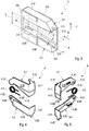
- FIG. 1 illustrated and known closing wedge system 1 represents a coupling device, with which - as described above - by means of a striker module 2 and a holding jaw module 3, a vehicle door 11 is coupled to a side wall frame 12 of a vehicle body 10.
- a coupling device is usually in addition a conventional vehicle lock (in FIG. 1 not shown), this coupling device leads to a stiffening of the vehicle body 10.
- FIG. 2 show a lock wedge module 2 and a holding jaw module 3 of a locking wedge system 1 according to the invention.
- a closing wedge holder 2.3 of the striker module 2 on opposite sides in the vertical direction R (z-direction) to a symmetry axis S each have a closing wedge 2.1 and 2.2 slidably disposed.
- These two closing wedges 2.1 and 2.2 have corresponding wedge surfaces to form a wedge edge 2.10 and 2.20.
- FIG. 3 comprises the holding jaw module 3 two spaced apart on a base plate 3.5 holding jaws 3.1 and 3.2, each with a keyway 3.11 and 3.21.
- the striker module 2 is introduced via an insertion end 3.3 of the holding jaw module 3 in the insertion direction E, so that the striker module 2 is located between the two holding jaws 3.1 and 3.2.
- the two locking wedges 2.1 and 2.2 are extended in opposite directions R (z-direction) from a non-coupling position in a coupling position, whereby the two locking wedges 2.1 and 2.2 with their end-side wedge surfaces in each of the adapted to the contour of these wedge surfaces keyways 3.11 and 3.21 are pressed and thus a non-positive and positive connection between the locking wedge module 2 and the holding jaw module 3 is produced.
- the wedges 2.1 and 2.2 of the striker module 2 are not aligned parallel to each other, more precisely, the wedge edges 2.10 and 2.20 of these strikers 2.1 and 2.2 are not parallel to the axis of symmetry S of the striker module 2, but extend in the insertion direction E obliquely toward each other.
- the wedge edge 2.10 of the closing wedge 2.1 and the wedge edge 2.20 of the closing wedge 2.2 each have an inclination angle ⁇ with the axis of symmetry S. This means that the end-side distance a of the two wedge edges 2.10 and 2.20 at the insertion-side end 2.4 of the striker module 2 is smaller than that Distance A at the opposite end 2.5.
- locking wedges 2.1 and 2.2 are also the splines 3.11 and 3.21 of the two holding jaws 3.1 and 3.2 running obliquely to the axis of symmetry S of the striker module 3 running.
- the holding jaw surface 3.12 receiving the keyway 3.12 has an inclination angle ⁇ relative to the symmetry axis S and the holding jaw surface 3.22 receiving the keyway 3.21 also has an inclination angle ⁇ with respect to the symmetry axis S, wherein the distance B of these two holding jaw surfaces 3.12 and 3.22 at the insertion end side 3.3 is greater than the distance b at the opposite end of the two holding jaws 3.1 and 3.2.
- a displacement unit 4 between a closure position between the two holding jaws 3.1 and 3.2 and a space between the two holding jaws 3.1 and 3.2 releasing open position between the guide rails 3.10 and 3.20 displaceable. Therefore, the holding jaw surfaces 3.12 and 3.22 of the holding jaws 3.1 and 3.2 together with the adjoining end faces of the two guide rails 3.10 and 3.20 form a uniform surface.
- the two guide rails 3.10 and 3.20 are frontally and frontally covered by an angle-shaped cover plate 3.6, wherein on the front side of a spring element 3.4 is arranged, the function will be explained below.
- a displacement unit 4 in different embodiments will be described below with reference to FIGS. 4 to 14 described.
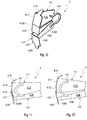
- the displacement unit 4 consists of a first strip-shaped thin plate element 4.1, a second strip-shaped thin plate element 4.2 and a leg spring as a spring element 4.3.
- Each of the lamellar elements 4.1 and 4.2 is L-shaped with a strip-shaped element 4.10 or 4.20 as a long leg of the L-shape and one of the strip-shaped element 4.10 or 4.20 at right angles projecting flange 4.11 or 4.21 designed as a short leg of the L-shape ,
- a circular connecting flange 4.13 with a short pivot axis 4.14 via which the two plate elements 4.1 and 4.2 are pivotally connected to each other.
- the first lamellar element 4.1 also has an outgoing from the connecting flange 4.13 and widening cone-shaped overlap region 4.12, which is delimited by means of a running into the flange 4.11 shoulder 4.120 with a thickness of the second fin element 4.2 corresponding shoulder height.
- this overlap area is 4.12 fan-like overlapped by the second blade element 4.2. If this overlapping area 4.12 is completely overlapped by the second lamella element 4.2, its side edge rests directly against the shoulder 4.120 and defines the open position of the displacement unit 4 in which it follows FIG. 9 located between the guide rails 3.10 and 3.20.
- FIG. 8 the free edge of the overlap region 4.12 at a running on the back of the second fin element 4.2 4.220 shoulder, which also has an overlap 4.22 of the second fin element 4.2 according to FIG. 5 Are defined.
- the leg spring is arranged as a spring element 4.3 on the pivot axis 4.14, wherein the ends are each fixed in a holding 4.16 of the first fin element 4.1 and in a holding 4.26 of the second fin element 4.2 such that the two fin elements 4.1 and 4.2 are pivoted against each other, so are biased in Auffambatationscardi D1 and D2.
- the closing wedge module 2 is clamped between the two holding jaws 3.1 and 3.2.
- the striker module 2 is extended from the holding jaw module 3, whereby the displacement unit 4 pushed from its open position between the guide rails 3.10 and 3.20 by a prestressed spring element 3.4 forward in the direction of Ein Industriesstirnseite 3.3 becomes.
- the closing unit 4 is fanned out due to the spring bias of the spring element 4.3, ie the two lamellar elements 4.1 and 4.2 are fanned out in their Auff kau ceremoniesscardi D1 or D2 until the outer edges positively abut positively against the holding jaw surfaces 3.12 and 3.22 of the two holding jaws 3.1 and 3.2 , wherein also on the flanges 4.11 and 4.21 together with their lugs 4.15 and 4.25 a positive connection of the holding jaws 3.1 and 3.2 is achieved at the Ein slaughterstirnseite 3.3 of the holding jaw module 3, as in FIG. 7 is shown.
- the striker module 2 is inserted via the insertion end 3.3 of the holding jaw module 3 between the holding jaws 3.1 and 3.2 while the displacement unit 4 against the spring force of the spring element 3.4 in the area of the guide rails 3.10 and 3.20 moved until this is in accordance with their open position FIG. 9 reached.
- the two plate elements 4.1 and 4.2 are compressed due to the oblique holding jaw surfaces 3.12 and 3.22 of the two holding jaws 3.1 and 3.2 until the overlap areas 4.12 and 4.23 are completely overlapped and therefore in the front view according to FIG. 9 only the shoulder 4.120 is visible.
- the displacement unit has 4 according to the FIGS. 4 and 5 of course, the same structure.
- FIG. 10 shows an alternative embodiment of the displacement unit 4.
- This displacement unit 4 according to FIG. 10 differs from the one according to the FIGS. 4 and 5 in that, instead of a leg spring as the spring element 4.3, an omega spring is provided. Otherwise, the structure of this displacement unit 4 corresponds to FIG. 10 the one according to the FIGS. 4 and 5 ,
- This displacement unit 4 also comprises a first plate element 4.1 and a second plate element 4.2.
- the omega spring as the spring element 4.3 connects the two plate elements 4.1 and 4.2, characterized in that one leg of the omega spring frictionally with the first fin element 4.1 and the other leg of the omega spring are positively connected to the second fin element 4.2.
- the two blade elements 4.1 and 4.2 are biased by means of this omega spring in Auff kau ceremoniesscardi, so that these blade elements 4.1 and 4.2 both in the open position according to FIG. 9 as well as in the closed position according to FIG. 3 pressed against the guide rails 3.10 and 3.20 or to the holding jaws 3.1 and 3.2.
- the first plate element 4.1 and the second plate element 4.2 each have no connecting flange 4.13 or 4.23 with associated pivot axis 4.14 or 4.24 axis opening and no holding 4.16 or 4.26.
- FIGS. 11 and 12 show a further alternative embodiment of a displacement unit 4, wherein instead of the omega spring of the displacement unit 4 after FIG. 10 an arcuate tension spring is used as the spring element 4.3.
- This spring element 4.3 connects the two fin elements 4.1 and 4.2 in the region of the flanges 4.11 and 4.21, wherein the convex Side of the tension spring in the direction of the flanges 4.11 and 4.21 shows.
- the connection of the two plate elements 4.1 and 4.2 is carried out to produce a direction of the fanning direction in D1 and D2 directed spring preload.
- the two blade elements 4.1 and 4.2 according to their structure that of the displacement unit 4 according to FIG. 10 ,
- the FIG. 11 shows the displacement unit 4 in its open position as shown FIG. 9 and the representation after FIG. 12 corresponds to the closing position according to FIG. 4 ,
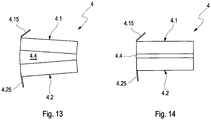
- FIGS. 13 and 14 show a last alternative embodiment of a displacement unit 4, which also includes a first fin elements 4.1 and a second fin elements 4.2, but which are cuboid with a thickness of the locking wedges 3.1 and 3.2 and the thickness of the guide rails 3.10 and 3.20 example.
- a displacement unit 4 also includes a first fin elements 4.1 and a second fin elements 4.2, but which are cuboid with a thickness of the locking wedges 3.1 and 3.2 and the thickness of the guide rails 3.10 and 3.20 example.
- the two lamellar elements 4.1 and 4.2 are connected by means of an elastic middle element 4.4 made of a plastic material form-locking and surface-locking in such a way that in the closed position of the sliding element 4 according to FIG. 13 due to the elastic property of the middle element 4.4, the two plate elements 4.1 and 4.2 pressed apart and pressed against the holding jaws 3.1 and 3.2 of the holding jaw module 3. If this displacement unit 4 is pushed out of this closure position into the open position between the guide rails 3.10 and 3.20, the two lamellar elements 4.1 and 4.2 due to the obliquely extending holding jaw surfaces 3.12 and 3.22 using the elastic property of the central element 4.4 in the closed position according to FIG. 14 pressed together.
- an elastic middle element 4.4 made of a plastic material form-locking and surface-locking in such a way that in the closed position of the sliding element 4 according to FIG. 13 due to the elastic property of the middle element 4.4, the two plate elements 4.1 and 4.2 pressed apart and pressed against the
Description
Die Erfindung betrifft ein Schließkeilsystem zur lösbaren Kopplung einer Fahrzeugklappe mit einem Strukturteil einer Fahrzeugkarosserie gemäß dem Oberbegriff des Patentanspruchs 1.The invention relates to a closing wedge system for the detachable coupling of a vehicle flap with a structural part of a vehicle body according to the preamble of
Ein gattungsbildendes Schließkeilsystem ist aus der
Das in
Ferner ist in dieser
Eine andere Ausführung des Haltebackenmoduls gemäß dieser
Eine solche Verschiebeeinheit eines Schließkeilsystems ist auch aus der
Die
Schließlich ist aus der
Es ist Aufgabe der Erfindung ein gegenüber dem Stand der Technik verbessertes Schließkeilsystem anzugeben.It is an object of the invention to provide a comparison with the prior art improved locking wedge system.
Diese Aufgabe wird gelöst durch ein Schließkeilsystem mit den Merkmalen des Patentanspruchs 1, mit den Merkmalen des Patentanspruchs 3 und mit den Merkmalen des Patentanspruchs 5.This object is achieved by a locking wedge system having the features of
Ein solches Schließkeilsystem zur lösbaren Kopplung einer Fahrzeugklappe mit einem Strukturteil einer Fahrzeugkarosserie umfasst:
- ein Schließkeilmodul mit zwei gegeneinander in senkrechter Richtung zu einer Symmetrieachse verschiebbar gelagerten Schließkeilen mit jeweils einer Keilkante und mit einem Schließkeilhalter zur verschiebbaren Aufnahme der Schließkeile, und
- ein Haltebackenmodul mit zwei, das Schließkeilmodul zwischen sich aufnehmenden Haltebacken mit jeweils einer Keilnut, wobei durch Auseinanderverlagern der Schließkeile ein Kraftschluss zwischen den Schließkeilen und den Haltebacken hergestellt ist, wobei
- a lock wedge module with two against each other in a direction perpendicular to a symmetry axis slidably mounted locking wedges, each with a wedge edge and with a striker holder for slidably receiving the strikers, and
- a holding jaw module with two, the locking wedge module between them receiving holding jaws, each with a keyway, wherein by Verscheinanderverlagern the closing wedges a frictional connection between the locking wedges and the holding jaws is made, wherein
Erfindungsgemäß ist gemäß der erstgenannten Lösung vorgesehen, dass
- das Haltebackenmodul mit Führungsschienen zur Führung einer Verschiebeeinheit zwischen einer die Haltebacken überbrückenden Verschlussposition und einer die Führungsschienen überbrückenden und die Aufnahme des Schließkeilmodul zulassenden Offenposition ausgebildet ist,
- die Verschiebeeinheit aus wenigstens zwei streifenförmigen Lamellenelementen gebildet ist, die fächerartig überlappend mittels einer an einem Ende der Lamellenelementen angeordneten Schwenkachse gegeneinander verschwenkbar verbunden sind, und
- die Verschiebeeinheit mit einem Federelement ausgebildet ist, mit welchem die Lamellenelemente beim Verschieben aus der Offenposition zwischen den Führungsschienen in die Verschlussposition zwischen den Haltebacken aufgefächert werden.
- the holding jaw module is designed with guide rails for guiding a displacement unit between a closing position bridging the holding jaws and an open position bridging the guide rails and permitting the reception of the closing wedge module,
- the displacement unit is formed from at least two strip-shaped lamellar elements, the fan-like overlapping by means of a at one end the lamellar elements arranged pivot axis are pivotally connected to each other, and
- the displacement unit is formed with a spring element, with which the plate elements are fanned out when moving from the open position between the guide rails in the closed position between the holding jaws.
Bei einer Fahrzeugtüre als Fahrzeugklappe, die mittels des Schließkeilsystems mit einem Seitentürrahmen als Strukturteil einer Fahrzeugkarosserie gekoppelt wird, stellt die nunmehr gegenüber der Symmetrieachse des Haltebackenmoduls schräg verlaufende Keilnut des Haltebackens eine Anlaufschräge für den zugehörigen Schließkeil dar, wenn dieser Haltebacken bezogen auf die Fahrzeughochrichtung der untere der beiden Haltebacken des Haltebackenmoduls ist. Mit einer solchen Anlaufschräge wird erreicht, dass eine schief nach unten hängende Fahrzeugtüre mit dieser Anlaufschräge automatisch in die richtige Position gebracht wird.In a vehicle door as a vehicle door, which is coupled by means of the locking wedge system with a side door frame as a structural part of a vehicle body, which now relative to the axis of symmetry of the holding jaw module obliquely extending keyway of the holding jaw is a starting slope for the associated striker, if this holding jaws relative to the vehicle vertical direction of the lower the two holding jaws of the holding jaw module is. With such a run-on slope is achieved that an obliquely down hanging vehicle door is automatically brought into this correct position with this run-in slope.
Es bietet sich natürlich an, nicht nur einen Haltebacken mit einer Anlaufschräge auszubilden, sondern beide Haltebacken eines Haltebackenmoduls mit einer Anlaufschräge, so dass die beiden Anlaufschrägen konisch aufeinander zu gerichtet sind. Die Schließkeile sind hieran mit schräg aufeinander zu verlaufenden Keilkanten angepasst.Of course, it makes sense not only to form a holding jaw with a run-on slope, but also both holding jaws of a holding jaw module with a run-on slope, so that the two run-on slopes are directed conically towards one another. The closing wedges are adapted thereto with obliquely running to each other wedge edges.
Mit einer solchen Verschiebeeinheit wird erfindungsgemäß die Anlaufschräge der Haltebacke ausgeglichen. Wird die Fahrzeugtüre als Fahrzeugklappe geschlossen, wird hierzu das Schließkeilmodul in das Haltebackenmodul eingeführt und gleichzeitig die Verschiebeeinheit aus der Verschlussposition in Richtung des Fahrzeuginneren zwischen die Führungsschienen in die Offenposition verschoben. Da die Haltebacken an der Einführstirnseite des Haltebackenmoduls einen größeren Abstand aufweisen als die zum Fahrzeuginneren zeigende Stirnseite wird die Verschiebeeinheit fächerartig überlappend zusammengeschoben. Wird umgekehrt die Fahrzeugtüre geöffnet, also das Schließkeilmodul aus dem Haltebackenmodul herausgeführt, wird die Verschiebeeinheit aus der zwischen den Führungsschienen liegenden Offenposition in die Verschlussposition zwischen den Haltebacken verschoben und dabei wieder aufgefächert, so dass die Haltebacken überbrückt werden.With such a displacement unit according to the invention, the starting slope of the holding jaw is compensated. If the vehicle door is closed as a vehicle flap, the closing wedge module is introduced into the holding jaw module for this purpose and at the same time the displacement unit is moved from the closed position in the direction of the vehicle interior between the guide rails into the open position. Since the holding jaws at the Einführstirnseite of the holding jaw module have a greater distance than the vehicle interior facing end side, the displacement unit is pushed together like a fan overlapping. Conversely, the vehicle door is opened, so the Latching module led out of the holding jaw module, the displacement unit is moved from lying between the guide rails open position in the closed position between the holding jaws and fanned out again, so that the holding jaws are bridged.
Vorzugsweise ist bei dieser Ausgestaltung der Erfindung das die beiden Lamellenelemente in Auffächerungsrichtung vorspannende Federelement als auf der Schwenkachse angeordnete Schenkelfeder ausgebildet, deren Enden sich jeweils gegen ein Lamellenelement der Verschiebeeinheit abstützen.Preferably, in this embodiment of the invention, the two lamellar elements biasing in Auffächerungsrichtung spring element is formed as arranged on the pivot axis leg spring whose ends are each supported against a lamella element of the displacement unit.
Erfindungsgemäß ist nach der zweitgenannten Lösung vorgesehen, dass
- das Haltebackenmodul mit Führungsschienen zur Führung einer Verschiebeeinheit zwischen einer die Haltebacken überbrückenden Verschlussposition und einer die Führungsschienen überbrückenden und die Aufnahme des Schließkeilmodul zulassenden Offenposition ausgebildet ist, und
- die Verschiebeeinheit aus wenigstens zwei streifenförmigen Lamellenelementen gebildet ist, die fächerartig überlappend mittels einer an einem Ende der Lamellenelemente angeordneten Spannfeder gegeneinander verschwenkbar verbunden sind, wobei die Lamellenelemente beim Verschieben aus der Offenposition zwischen den Führungsschienen in die Verschlussposition zwischen den Haltebacken aufgefächert werden.
- the holding jaw module is designed with guide rails for guiding a displacement unit between a locking position bridging the holding jaws and an open position bridging the guide rails and allowing the reception of the closing wedge module, and
- the displacement unit is formed from at least two strip-shaped lamellar elements, which are connected in a fan-like overlapping manner by means of a tension spring arranged at one end of the lamellar elements, wherein the lamellar elements are fanned out from the open position between the guide rails into the closed position between the holding jaws during displacement.
Auch mit einer solchen Verschiebeeinheit wird erfindungsgemäß die Anlaufschräge der Haltebacke ausgeglichen und erfüllt die gleiche Funktion wie die oben beschriebene Verschiebeeinheit. Der Unterschied zur oben beschriebenen Verschiebeeinheit liegt darin, dass anstelle einer Schenkelfeder eine Spannfeder eingesetzt wird, die gleichzeitig die beiden Lamellenelemente verbindet. Vorzugsweise ist das Federelement als Omega-Feder ausgebildet. Mit einer solchen Omega-Feder werden gleichzeitig die beiden Lamellenelemente verbunden.Even with such a displacement unit according to the invention, the starting slope of the holding jaw is compensated and fulfills the same function as the displacement unit described above. The difference from the displacement unit described above is that instead of a leg spring, a tension spring is used, which simultaneously connects the two plate elements. Preferably, the spring element is designed as an omega spring. With such an omega spring, the two lamellar elements are connected simultaneously.
Erfindungsgemäß ist nach der drittgenannten Lösung vorgesehen, dass
- das Haltebackenmodul mit Führungsschienen zur Führung einer Verschiebeeinheit zwischen einer die Haltebacken überbrückenden Verschlussposition und einer die Führungsschienen überbrückenden und die Aufnahme des Schließkeilmodul zulassenden Offenposition ausgebildet ist, und
- die Verschiebeeinheit aus wenigstens zwei streifenförmigen Lamellenelementen gebildet ist, die mittels eines elastischen Mittelelementes derart verbunden sind, dass unter Nutzung der elastischen Eigenschaft des Mittelelementes die Lamellenelemente aus der Offenposition auffächerbar oder aus der Verschlussposition wieder zusammenlegbar sind.
- the holding jaw module is designed with guide rails for guiding a displacement unit between a locking position bridging the holding jaws and an open position bridging the guide rails and allowing the reception of the closing wedge module, and
- the displacement unit is formed from at least two strip-shaped lamellar elements, which are connected by means of an elastic middle element such that the lamellar elements can be fanned out of the open position or be folded out of the closed position again using the elastic property of the middle element.
Auch mit einer solchen Verschiebeeinheit wird erfindungsgemäß die Anlaufschräge der Haltebacke ausgeglichen und erfüllt die gleiche Funktion wie die oben beschriebene Verschiebeeinheit. Der Unterschied zur oben beschriebenen Verschiebeeinheit liegt darin, dass die beiden Lamellenelemente mittels eines elastischen Mittelelementes verbunden sind, welches in der Verschlussposition die beiden Lamellenelemente auseinanderdrückt, so dass diese an den Haltebacken anliegen. Mit dem Verschieben in die Offenstellung werden die beiden Lamellenelemente aufgrund der Elastizität des Mittelelementes zusammengedrückt. Damit kann eine einteilige Verschiebeeinheit mit einem elastischen Mittelelement geschaffen werden.Even with such a displacement unit according to the invention, the starting slope of the holding jaw is compensated and fulfills the same function as the displacement unit described above. The difference from the above-described displacement unit lies in the fact that the two lamellar elements are connected by means of an elastic central element which, in the closed position, presses apart the two lamellar elements, so that these rest against the holding jaws. By moving into the open position, the two lamellar elements are compressed due to the elasticity of the central element. Thus, a one-piece displacement unit can be created with an elastic central element.
Zudem ist es besonders vorteilhaft, wenn weiterbildungsgemäß im Bereich der Führungsschienen ein Federelement angeordnet ist, mit welchem die Verschiebeeinheit in Richtung der Verschlussstellung vorgespannt ist. Mit einem solchen Federelement wird sichergestellt, dass die Verschiebeeinheit in ihrer Verschlussposition verbleibt. Die Verschiebeeinheit wird gegen die Federkraft dieses Federelementes in ihre Offenposition verschoben.Moreover, it is particularly advantageous if, in accordance with further development, a spring element is arranged in the region of the guide rails, with which the displacement unit is biased in the direction of the closure position. With such a spring element ensures that the displacement unit remains in its closed position. The displacement unit is moved against the spring force of this spring element in its open position.
Schließlich sieht eine letzte vorteilhafte Weiterbildung der Erfindung vor, dass die Lamellenelemente mit eine Stirnseite des Haltebackenmoduls abdeckende Flansche mit an die Keilform der Keilnuten angepassten Nasen ausgebildet sind. Damit ist sichergestellt, dass auch die Einführstirnseite des Haltebackenmoduls bei offener Fahrzeugtür abgedeckt ist und einen optimalen Designeindruck vermittelt.Finally, a last advantageous development of the invention provides that the lamellar elements cover with an end face of the holding jaw module Flanges are formed with adapted to the wedge shape of the keyways lugs. This ensures that the Einführstirnseite the holding jaw module is covered with the vehicle door open and gives an optimal design impression.
Die Erfindung wird nachfolgend anhand von Ausführungsbeispielen unter Bezugnahme auf die beigefügten Figuren ausführlich beschrieben. Es zeigen:
Figur 1- eine schematische Darstellung einer Fahrzeugkarosserie mit einem Schließkeilsystem gemäß Stand der Technik,
Figur 2- ein Schließkeilmodul eines Schließkeilsystems gemäß der Erfindung,
Figur 3- ein mit dem
Schließkeilmodul gemäß Figur 2 zusammenwirkendes Haltebackenmodul gemäß der Erfindung, Figur 4- eine perspektivische Darstellung einer Verschiebeeinheit des Schließkeilmoduls gemäß
Figur 3 in einer Vorderansicht, - Figur 5
- eine perspektivische Darstellung einer Verschiebeeinheit gemäß
Figur 4 in einer Rückansicht, - Figur 6
- eine Darstellung der Verschiebeeinheit gemäß
den Figuren 4 und 5 in ihrer Verschlussposition, - Figur 7
- eine perspektivische Darstellung des Haltebackenmoduls mit der Verschiebeeinheit gemäß
Figur 6 , - Figur 8
- eine Darstellung der Verschiebeeinheit gemäß
den Figuren 4 und 5 in ihre Offenposition, - Figur 9
- eine perspektivische Darstellung des Haltebackenmoduls mit der Verschiebeeinheit gemäß
Figur 8 , - Figur 10
- eine perspektivische Darstellung einer weiteren Verschiebeeinheit des Schließkeilmoduls gemäß
Figur 3 in einer Rückansicht, Figur 11- eine schematische Darstellung einer weiteren Verschiebeeinheit des Schließkeilmoduls gemäß
Figur 3 im Zustand einer Offenposition, Figur 12- eine schematische Darstellung der Verschiebeeinheit nach
Figur 11 im Zustand einer Verschlussposition, - Figur 13
- eine schematische Darstellung einer weiteren Verschiebeeinheit des Schließkeilmoduls gemäß
Figur 3 im Zustand einer Offenposition, und - Figur 14
- eine schematische Darstellung der Verschiebeeinheit nach
Figur 13 im Zustand einer Verschlussposition.
- FIG. 1
- a schematic representation of a vehicle body with a locking wedge system according to the prior art,
- FIG. 2
- a striker module of a striker system according to the invention,
- FIG. 3
- one with the lock wedge module according to
FIG. 2 cooperating holding jaw module according to the invention, - FIG. 4
- a perspective view of a displacement unit of the striker module according to
FIG. 3 in a front view, - FIG. 5
- a perspective view of a displacement unit according to
FIG. 4 in a rear view, - FIG. 6
- a representation of the displacement unit according to the
FIGS. 4 and 5 in its closed position, - FIG. 7
- a perspective view of the holding jaw module with the displacement unit according to
FIG. 6 . - FIG. 8
- a representation of the displacement unit according to the
FIGS. 4 and 5 in their open position, - FIG. 9
- a perspective view of the holding jaw module with the displacement unit according to
FIG. 8 . - FIG. 10
- a perspective view of a further displacement unit of the striker module according to
FIG. 3 in a rear view, - FIG. 11
- a schematic representation of a further displacement unit of the striker module according to
FIG. 3 in the state of an open position, - FIG. 12
- a schematic representation of the displacement unit according to
FIG. 11 in the state of a closed position, - FIG. 13
- a schematic representation of a further displacement unit of the striker module according to
FIG. 3 in the state of an open position, and - FIG. 14
- a schematic representation of the displacement unit according to
FIG. 13 in the state of a closed position.
Das in
Die
Nach
Mittels einer nicht dargestellten Antriebseinrichtung werden die beiden Schließkeile 2.1 und 2.2 in entgegengesetzten Richtungen R (z-Richtung) aus einer Nichtkoppelstellung in eine Koppelstellung ausgefahren, wodurch die beiden Schließkeile 2.1 und 2.2 mit ihren endseitigen Keilflächen jeweils in die an die Kontur dieser Keilflächen angepassten Keilnuten 3.11 und 3.21 gedrückt werden und damit eine kraft- und formschlüssige Verbindung zwischen dem Schließkeilmodul 2 und dem Haltebackenmodul 3 hergestellt wird.By means of a drive device, not shown, the two locking wedges 2.1 and 2.2 are extended in opposite directions R (z-direction) from a non-coupling position in a coupling position, whereby the two locking wedges 2.1 and 2.2 with their end-side wedge surfaces in each of the adapted to the contour of these wedge surfaces keyways 3.11 and 3.21 are pressed and thus a non-positive and positive connection between the locking
Die Schließkeile 2.1 und 2.2 des Schließkeilmoduls 2 sind jedoch nicht parallel zueinander ausgerichtet, genauer gesagt die Keilkanten 2.10 und 2.20 dieser Schließkeile 2.1 und 2.2 verlaufen nicht parallel zur Symmetrieachse S des Schließkeilmoduls 2, sondern verlaufen in Einführrichtung E schräg aufeinander zu. So bildet die Keilkante 2.10 des Schließkeils 2.1 sowie die Keilkante 2.20 des Schließkeils 2.2 jeweils einen Neigungswinkel α mit der Symmetrieachse S. Dies bedeutet, dass der endseitige Abstand a der beiden Keilkanten 2.10 und 2.20 an der einführseitigen Stirnseite 2.4 des Schließkeilmoduls 2 kleiner ist als der Abstand A an der gegenüberliegenden Stirnseite 2.5. In Anpassung an diese schräg gegenüber der Symmetrieachse S verlaufenden Schließkeile 2.1 und 2.2 sind auch die Keilnuten 3.11 und 3.21 der beiden Haltebacken 3.1 und 3.2 schräg zur Symmetrieachse S des Schließkeilmoduls 3 verlaufend ausgeführt. Dies bedeutet, dass die die Keilnut 3.11 aufnehmende Haltebackenfläche 3.12 gegenüber der Symmetrieachse S einen Neigungswinkel α und ebenso die die Keilnut 3.21 aufnehmende Haltebackenfläche 3.22 ebenso gegenüber der Symmetrieachse S einen Neigungswinkel α aufweist, wobei der Abstand B dieser beiden Haltebackenflächen 3.12 und 3.22 an der Einführstirnseite 3.3 größer ist als der Abstand b am gegenüberliegenden Ende der beiden Haltebacken 3.1 und 3.2. Somit passen bei der Einführung des Schließkeilmoduls 2 in das Haltebackenmodul 3 die jeweiligen konusförmigen Verläufe der beiden Schließkeile 2.1 und 2.2 sowie der beiden Haltebacken 3.1 und 3.2 zusammen.However, the wedges 2.1 and 2.2 of the
Es ist natürlich auch möglich, bezogen auf die Fahrzeughochrichtung (z-Richtung) nur den unteren Schließkeil 2.2 des Schließkeilmoduls 2 mit einer gegenüber der Symmetrieachse S schräg verlaufenden Keilkante 2.20 auszubilden. Die Keilkante 2.10 des oberen Schließkeils 2. 1 verläuft dann entsprechend dem Stand der Technik parallel zur Symmetrieachse S. Hieran angepasst sind die Haltebacken 3.1 und 3.2 des Haltebackenmoduls 3, wobei bezogen auf die Fahrzeughochrichtung (z-Richtung) nur der untere Haltebacken 3.2 gegenüber der Symmetrieachse S eine schräg verlaufende Keilnut 3.21 bzw. Haltebackenfläche 3.22 aufweist.Of course, it is also possible, based on the vehicle vertical direction (z-direction) only the lower striker 2.2 of the
An den zur Einführstirnseite 3.3 gegenüberliegenden Enden der beiden Haltebacken 3.1 und 3.2 schließen sich jeweils eine Führungsschiene 3.10 und 3.20 zur Aufnahme einer in
Die beiden Führungsschienen 3.10 und 3.20 werden stirnseitig und vorderseitig von einer winkelförmigen Abdeckplatte 3.6 abgedeckt, wobei an der Stirnseite ein Federelement 3.4 angeordnet ist, dessen Funktion weiter unten erläutert wird.The two guide rails 3.10 and 3.20 are frontally and frontally covered by an angle-shaped cover plate 3.6, wherein on the front side of a spring element 3.4 is arranged, the function will be explained below.
Eine Verschiebeeinheit 4 in unterschiedlichen Ausführungsformen wird nachfolgend anhand der
Die Verschiebeeinheit 4 gemäß den
An dem zum Flansch 4.11 gegenüberliegenden Ende des streifenförmigen Elementes 4.10 schließt sich ein kreisförmiger Verbindungsflansch 4.13 mit einer kurzen Schwenkachse 4.14 an, über welche die beiden Lamellenelemente 4.1 und 4.2 gegeneinander verschwenkbar verbunden werden. Hierzu weist das zweite Lamellenelement 4.2 gegenüberliegend zum Flansch 4.21 ebenso einen Verbindungsflansch 4.24 mit einer an den Durchmesser der Schwenkachse 4.14 angepassten Achsenöffnung 4.24 auf.At the opposite end to the flange 4.11 4.10 of the strip-shaped element is followed by a circular connecting flange 4.13 with a short pivot axis 4.14, via which the two plate elements 4.1 and 4.2 are pivotally connected to each other. For this purpose, the second plate element 4.2 opposite to the flange 4.21 as well as a connecting flange 4.24 with an adapted to the diameter of the pivot axis 4.14 axis opening 4.24.
Das erste Lamellenelement 4.1 weist ferner einen von dem Verbindungsflansch 4.13 ausgehenden und sich konusförmig verbreiternden Überlappungsbereich 4.12, auf, der mittels einer bis in den Flansch 4.11 laufenden Schulter 4.120 mit einer der Dicke des zweiten Lamellenelementes 4.2 entsprechenden Schulterhöhe abgegrenzt ist. Im über die Schwenkachse 4.14 verbundenen Zustand der beiden Lamellenelemente 4.1 und 4.2 wird dieser Überlappungsbereich 4.12 fächerartig von dem zweiten Lamellenelement 4.2 überlappt. Wird dieser Überlappungsbereich 4.12 vollständig von dem zweiten Lamellenelement 4.2 überlappt, liegt dessen Seitenkante direkt an der Schulter 4.120 an und definiert die Offenposition der Verschiebeeinheit 4, in welcher sie sich gemäß
Im verbundenen Zustand der beiden Lamellenelemente 4.1 und 4.2 ist die Schenkelfeder als Federelement 4.3 auf der Schwenkachse 4.14 angeordnet, wobei deren Enden jeweils in eine Haltenut 4.16 des ersten Lamellenelementes 4.1 und in eine Haltenut 4.26 des zweiten Lamellenelementes 4.2 derart fixiert sind, dass die beiden Lamellenelemente 4.1 und 4.2 gegeneinander verschwenkt werden, also in Auffächerungsrichtung D1 bzw. D2 vorgespannt sind.In the connected state of the two blade elements 4.1 and 4.2, the leg spring is arranged as a spring element 4.3 on the pivot axis 4.14, wherein the ends are each fixed in a holding 4.16 of the first fin element 4.1 and in a holding 4.26 of the second fin element 4.2 such that the two fin elements 4.1 and 4.2 are pivoted against each other, so are biased in Auffächerungsrichtung D1 and D2.
Befindet sich die Verschiebeeinheit 4 in ihrer Offenposition zwischen den beiden Führungsschienen 3.10 und 3.20 wird das Schließkeilmodul 2 zwischen den beiden Haltebacken 3.1 und 3.2 verspannt. Mit dem Öffnen der Fahrzeugtüre wird das Schließkeilmodul 2 aus dem Haltebackenmodul 3 ausgefahren, wodurch die Verschiebeeinheit 4 aus ihrer Offenposition zwischen den Führungsschienen 3.10 und 3.20 von einem vorgespannten Federelement 3.4 nach vorne in Richtung der Einführstirnseite 3.3 geschoben wird. Hierbei wird die Schließeinheit 4 aufgrund der Federvorspannung des Federelementes 4.3 aufgefächert, d.h. die beiden Lamellenelemente 4.1 und 4.2 werden jeweils in ihre Auffächerungsrichtung D1 bzw. D2 aufgefächert, bis deren äußeren Kanten formschlüssig an den Haltebackenflächen 3.12 und 3.22 der beiden Haltebacken 3.1 und 3.2 formschlüssig anliegen, wobei auch über die Flansche 4.11 und 4.21 zusammen mit deren Nasen 4.15 und 4.25 ein Formschluss der Haltebacken 3.1 und 3.2 an der Einführstirnseite 3.3 des Haltebackenmoduls 3 erreicht wird, wie dies in
Zum Schließen der Fahrzeugtüre wird das Schließkeilmodul 2 über die Einführstirnseite 3.3 des Haltebackenmoduls 3 zwischen die Haltebacken 3.1 und 3.2 eingeführt und dabei die Verschiebeeinheit 4 entgegen der Federkraft des Federelementes 3.4 in den Bereich der Führungsschienen 3.10 und 3.20 verschoben, bis diese ihre Offenposition gemäß
Wenn das Haltebackenmodul 3 nur mit einer einzigen schräg verlaufenden Keilnut 3.21 des unteren Haltebackens 3.1 ausgeführt ist, weist die Verschiebeeinheit 4 gemäß den
Die
Diese Verschiebeeinheit 4 umfasst ebenso ein erstes Lamellenelement 4.1 und ein zweites Lamellenelement 4.2. Die Omega-Feder als Federelement 4.3 verbindet die beiden Lamellenelemente 4.1 und 4.2 dadurch, dass ein Schenkel der Omega-Feder kraftschlüssig mit dem ersten Lamellenelement 4.1 und der andere Schenkel der Omega-Feder kraftschlüssig mit dem zweiten Lamellenelement 4.2 verbunden sind. Auch bei dieser Verschiebeeinheit 4 sind die beiden Lamellenelemente 4.1 und 4.2 mittels dieser Omega-Feder in Auffächerungsrichtung vorgespannt, so dass diese Lamellenelemente 4.1 und 4.2 sowohl in der Offenposition gemäß
Mit der Verwendung einer Omega-Feder als Federelement 3.4 weist das erste Lamellenelement 4.1 und das zweite Lamellenelement 4.2 jeweils keinen Verbindungsflansch 4.13 bzw. 4.23 mit zugehöriger Schwenkachse 4.14 bzw. Achsenöffnung 4.24 und keine Haltenut 4.16 bzw. 4.26 auf.With the use of an omega spring as a spring element 3.4, the first plate element 4.1 and the second plate element 4.2 each have no connecting flange 4.13 or 4.23 with associated pivot axis 4.14 or 4.24 axis opening and no holding 4.16 or 4.26.
Die
Die
Die beiden Lamellenelemente 4.1 und 4.2 sind mittels eines elastischen Mittelelementes 4.4 aus einem Kunststoffmaterial form- und flächenschlüssig derart miteinander verbunden, dass in der Verschlussposition des Verschiebeelementes 4 gemäß
Mit einem solchen elastischen Mittelelement 4.4 kann die Verschiebeeinheit 4 gemäß den
- 11
- SchließkeilsystemCotter System
- 22
- SchließkeilmodulCotter module
- 2.12.1
- Schließkeilcotter
- 2.102.10
- Keilkante des Schließkeils 2.1Wedge edge of the closing wedge 2.1
- 2.22.2
- Schließkeilcotter
- 2.202.20
- Keilkante des Schließkeils 2.2Wedge edge of the closing wedge 2.2
- 2.32.3
- SchließkeilhalterCotter holder
- 2.42.4
-
Stirnseite des Schließkeilmoduls 2Front side of the
striker module 2 - 2.52.5
-
Stirnseite des Schließkeilmoduls 2Front side of the
striker module 2
- 33
- HaltebackenmodulHolding back module
- 3.13.1
-
Haltebacke des Haltebackenmoduls 3Holding jaw of the holding
jaw module 3 - 3.103.10
- Führungsschieneguide rail
- 3.113.11
- Keilnut der Haltebacke 3.1Keyway of holding jaw 3.1
- 3.123.12
- HaltebackenflächeHolding baking surface
- 3.23.2
-
Haltebacke des Haltebackenmoduls 3Holding jaw of the holding
jaw module 3 - 3.203.20
- Führungsschieneguide rail
- 3.213.21
- Keilnut der Haltebacke 3.2Keyway of holding jaw 3.2
- 3.223.22
- HaltebackenflächeHolding baking surface
- 3.33.3
-
Einführstirnseite des Haltebackenmoduls 3Einführstirnseite the holding
jaw module 3 - 3.43.4
- Federelementspring element
- 3.53.5
- Grundplattebaseplate
- 3.63.6
- Abdeckplattecover
- 44
- Verschiebeeinheitdisplacement unit
- 4.14.1
- erstes Lamellenelementfirst lamella element
- 4.104.10
- streifenförmiges Element des ersten Lamellenelementes 4.1strip-shaped element of the first fin element 4.1
- 4.114.11
- Flansch des streifenförmigen Elementes 4.10Flange of the strip-shaped element 4.10
- 4.124.12
- Überlappungsbereich des ersten Lamellenelementes 4.10Overlap area of the first fin element 4.10
- 4.1204120
- Schulter des ersten Lamellenelementes 4.1Shoulder of the first lamellar element 4.1
- 4.134.13
- Verbindungsflansch des streifenförmigen Elementes 4.10Connecting flange of the strip-shaped element 4.10
- 4.144.14
- Schwenkachseswivel axis
- 4.154.15
- Nase des Flansches 4.11Nose of the flange 4.11
- 4.164.16
- Haltenutretaining groove
- 4.24.2
- zweites Lamellenelementsecond lamellar element
- 4.204.20
- streifenförmiges Element des zweiten Lamellenelementes 4.2strip-shaped element of the second fin element 4.2
- 4.214.21
- Flansch des streifenförmigen Elementes 4.20Flange of the strip-shaped element 4.20
- 4.224.22
- Schulter des zweiten Lamellenelementes 4.2Shoulder of the second fin element 4.2
- 4.2204220
- Schulter des zweiten Lamellenelementes 4.2Shoulder of the second fin element 4.2
- 4.234.23
- Verbindungsflansch des streifenförmigen Elementes 4.20Connecting flange of the strip-shaped element 4.20
- 4.244.24
- Achsenöffnung des Verbindungsflansches 4.23Axle opening of connecting flange 4.23
- 4.254.25
- Nase des Flansches 4.21Nose of the flange 4.21
- 4.264.26
- Haltenutretaining groove
- 4.34.3
- Federelementspring element
- 4.44.4
- Mittelelementmiddle element
- 1010
- Fahrzeugkarosserievehicle body
- 1111
- Fahrzeugklappe, Fahrzeugtüre der Fahrzeugkarosserie 10Vehicle door, vehicle door of the vehicle body 10
- 1212
- Strukturteil, Seitenwandrahmen der Fahrzeugkarosserie 10Structural part, side wall frame of the vehicle body 10
Claims (7)
- Locking wedge system (1) for releasably coupling a vehicle flap (11) to a structural part (12) of a vehicle body, comprising- a locking wedge module (2) with two locking wedges (2.1, 2.2), which are mounted displaceably with respect to one another in perpendicular direction (R) to an axis of symmetry (S), with a respective wedge edge (2.10, 2.20) and with a locking wedge holder (2.3) for displaceably receiving the locking wedges (2.1, 2.2), and- a retaining jaw module (3) with two retaining jaws (3.1, 3.2), which receive the locking wedge module (2) between them, with a respective wedge groove (3.11, 3.21), wherein a force fit is produced between the locking wedges (2.1, 2.2) and the retaining jaws (3.1, 3.2) by moving the locking wedges (2.1, 2.2) apart, wherein- a wedge edge (2.10, 2.20) of at least one locking wedge (2.1, 2.2) and the wedge groove (3.11, 3.21) of a retaining jaw (3.1, 3.2) that receives said wedge edge (2.10, 2.20) are designed to extend at an inclination with respect to the axis of symmetry (S) of the locking wedges (2.1, 2.2) and the retaining jaws (3.1, 3.2),characterised in that- the retaining jaw module (3) is designed with guide rails (3.10, 3.20) to guide a displacement unit (4) between a locked position bridging the retaining jaws (3.1, 3.2) and an open position bridging the guide rails (3.10, 3.20) and allowing the receiving of the locking wedge module (2),- the displacement unit (4) is formed of at least two strip-shaped plate elements (4.1, 4.2), which are connected pivotably against each other in an overlapping fan-like manner by means of a pivot axis (4.14) arranged at one end of the plate elements (4.1, 4.2), and- the displacement unit (4) is designed with a spring element (4.3), with which the plate elements (4.1, 4.2) are fanned out when displaced from the open position between the guide rails (3.10, 3.20) into the locked position between the retaining jaws (3.1, 3.2).
- Locking wedge system (1) according to claim 1,
characterised in that the spring element (4.3) is designed as spring with legs arranged on the pivot axis (4.14), the ends of said torsion spring each resting against a plate element (4.1, 4.2) of the displacement unit (4). - Locking wedge system (1) for releasably coupling a vehicle flap (11) to a structural part (12) of a vehicle body, comprising- a locking wedge module (2) with two locking wedges (2.1, 2.2), which are mounted displaceably with respect to one another in perpendicular direction (R) to an axis of symmetry (S), with a respective wedge edge (2.10, 2.20) and with a locking wedge holder (2.3) for displaceably receiving the locking wedges (2.1, 2.2), and- a retaining jaw module (3) with two retaining jaws (3.1, 3.2), which receive the locking wedge module (2) between them, with a respective wedge groove (3.11, 3.21), wherein a force fit is produced between the locking wedges (2.1, 2.2) and the retaining jaws (3.1, 3.2) by moving the locking wedges (2.1, 2.2) apart, wherein- a wedge edge (2.10, 2.20) of at least one locking wedge (2.1, 2.2) and the wedge groove (3.11, 3.21) of a retaining jaw (3.1, 3.2) that receives said wedge edge (2.10, 2.20) are designed to extend at an inclination with respect to the axis of symmetry (S) of the locking wedges (2.1, 2.2) and the retaining jaws (3.1, 3.2),characterised in that- the retaining jaw module (3) is designed with guide rails (3.10, 3.20) to guide a displacement unit (4) between a locked position bridging the retaining jaws (3.1, 3.2) and an open position bridging the guide rails (3.10, 3.20) and allowing the receiving of the locking wedge module (2), and- the displacement unit (4) is formed of at least two strip-shaped plate elements (4.1, 4.2), which are connected pivotably against each other in an overlapping fan-like manner by means of a tension spring arranged as spring element (4.3) at one end of the plate elements (4.1, 4.2), wherein the plate elements (4.1, 4.2) are fanned out when displaced from the open position between the guide rails (3.10, 3.20) into the locked position between the retaining jaws (3.1, 3.2).
- Locking wedge system (1) according to claim 3,
characterised in that the spring element (4.3) is designed as omega spring. - Locking wedge system (1) for releasably coupling a vehicle flap (11) to a structural part (12) of a vehicle body, comprising- a locking wedge module (2) with two locking wedges (2.1, 2.2), which are mounted displaceably with respect to one another in perpendicular direction (R) to an axis of symmetry (S), with a respective wedge edge (2.10, 2.20) and with a locking wedge holder (2.3) for displaceably receiving the locking wedges (2.1, 2.2), and- a retaining jaw module (3) with two retaining jaws (3.1, 3.2), which receive the locking wedge module (2) between them, with a respective wedge groove (3.11, 3.21), wherein a force fit is produced between the locking wedges (2.1, 2.2) and the retaining jaws (3.1, 3.2) by moving the locking wedges (2.1, 2.2) apart, wherein- a wedge edge (2.10, 2.20) of at least one locking wedge (2.1, 2.2) and the wedge groove (3.11, 3.21) of a retaining jaw (3.1, 3.2) that receives said wedge edge (2.10, 2.20) are designed to extend at an inclination with respect to the axis of symmetry (S) of the locking wedges (2.1, 2.2) and the retaining jaws (3.1, 3.2),characterised in that- the retaining jaw module (3) is designed with guide rails (3.10, 3.20) to guide a displacement unit (4) between a locked position bridging the retaining jaws (3.1, 3.2) and an open position bridging the guide rails (3.10, 3.20) and allowing the receiving of the locking wedge module (2), and- the displacement unit (4) is formed of at least two strip-shaped plate elements (4.1, 4.2), which are connected by means of an elastic centre element (4.4) in such a way that, using the elastic property of the centre element (4.4), the plate elements (4.1, 4.2) can be fanned out from the open position or folded up again from the locked position.
- Locking wedge system (1) according to any one of claims 1 to 5,
characterised in that there is arranged in the region of the guide rails (3.10, 3.20) a spring element (3.4), with which the displacement unit (4) is pretensioned in direction of the locked position. - Locking wedge system (1) according to any one of claims 1 to 6,
characterised in that the plate elements (4.1, 4.2) are designed with flanges (4.11, 4.21) covering a front face of the retaining jaw module (3) and having lugs (4.15, 4.25) adapted to the wedge shape of the wedge grooves (3.11, 3.21).
Applications Claiming Priority (2)
| Application Number | Priority Date | Filing Date | Title |
|---|---|---|---|
| DE102016004279.6A DE102016004279A1 (en) | 2016-04-07 | 2016-04-07 | Lock wedge system for releasably coupling a vehicle door with a structural part of a vehicle body |
| PCT/EP2017/000417 WO2017174186A1 (en) | 2016-04-07 | 2017-04-05 | Locking wedge system for releasably coupling a vehicle flap to a structural part of a vehicle body |
Publications (2)
| Publication Number | Publication Date |
|---|---|
| EP3440293A1 EP3440293A1 (en) | 2019-02-13 |
| EP3440293B1 true EP3440293B1 (en) | 2019-11-06 |
Family
ID=58503563
Family Applications (1)
| Application Number | Title | Priority Date | Filing Date |
|---|---|---|---|
| EP17716125.4A Active EP3440293B1 (en) | 2016-04-07 | 2017-04-05 | Locking wedge system for releasably coupling a vehicle flap to a structural part of a vehicle body |
Country Status (3)
| Country | Link |
|---|---|
| EP (1) | EP3440293B1 (en) |
| DE (1) | DE102016004279A1 (en) |
| WO (1) | WO2017174186A1 (en) |
Families Citing this family (1)
| Publication number | Priority date | Publication date | Assignee | Title |
|---|---|---|---|---|
| DE102018132665A1 (en) * | 2018-12-18 | 2020-06-18 | Kiekert Aktiengesellschaft | POSITIONING DEVICE FOR A MOTOR VEHICLE DOOR ELEMENT |
Family Cites Families (5)
| Publication number | Priority date | Publication date | Assignee | Title |
|---|---|---|---|---|
| JPH10227165A (en) * | 1997-02-14 | 1998-08-25 | Tokyo Magnet Oyo Seihin Kk | Door opening and closing lock device |
| DE10315565B4 (en) * | 2003-04-05 | 2006-07-13 | Audi Ag | Vehicle body and power lock |
| DE102012011420A1 (en) | 2012-06-08 | 2013-12-12 | Audi Ag | Coupling device for releasably connecting a pivotally mounted body part, such as vehicle door, rear or front door with a vehicle structural part of a vehicle body |
| DE102012025336A1 (en) * | 2012-12-21 | 2014-06-26 | Audi Ag | Vehicle locking device for a vehicle using a coupling device |
| DE102012025392B3 (en) | 2012-12-24 | 2014-02-20 | Audi Ag | Covering device for a with a locking wedge module in a connection of a vehicle door with a side wall frame of a vehicle body causing releasable coupling bringable holding jaw module |
-
2016
- 2016-04-07 DE DE102016004279.6A patent/DE102016004279A1/en not_active Withdrawn
-
2017
- 2017-04-05 EP EP17716125.4A patent/EP3440293B1/en active Active
- 2017-04-05 WO PCT/EP2017/000417 patent/WO2017174186A1/en active Application Filing
Non-Patent Citations (1)
| Title |
|---|
| None * |
Also Published As
| Publication number | Publication date |
|---|---|
| WO2017174186A1 (en) | 2017-10-12 |
| DE102016004279A1 (en) | 2017-10-12 |
| EP3440293A1 (en) | 2019-02-13 |
Similar Documents
| Publication | Publication Date | Title |
|---|---|---|
| DE202006021264U1 (en) | Door and window frame with an undercut engagement area for a gear unit | |
| WO2011095414A1 (en) | Adjustment device having a deflection assembly | |
| AT519903B1 (en) | Rail for guiding a slide of a furniture door | |
| DE8309452U1 (en) | Motor vehicle door | |
| DE102009001318A1 (en) | Longitudinal guide for motor vehicle seats, which are both adjustable in a longitudinal direction and removable | |
| EP1275541A1 (en) | Module, specially a sliding roof module for a vehicle | |
| EP2935739B1 (en) | Cover device for a retaining jaws module that can be detachably coupled to a striker plate module to bring about the connection of a vehicle door and a side wall frame of a vehicle body | |
| EP2935734B1 (en) | Vehicle locking apparatus for a vehicle using a coupling device | |
| DE202010007430U1 (en) | Device with an attachment device and drawer | |
| EP0385167A1 (en) | Cable-return pad | |
| EP3440293B1 (en) | Locking wedge system for releasably coupling a vehicle flap to a structural part of a vehicle body | |
| DE2032517A1 (en) | Frame gear for windows, doors or the like | |
| DE2044198A1 (en) | Length-adjustable rod coupling for connecting rod fittings | |
| DE102019200066A1 (en) | Hatch arrangement for a recreational vehicle | |
| EP1352143B1 (en) | Adjustable driver for joining a window pane to a window lifter device of a vehicle door | |
| EP2995502B1 (en) | Roof rack assembly for a motor vehicle | |
| DE10040597A1 (en) | Motor vehicle roof with sliding roof panel has two bearing units with pivot levers coupled to panel and driver element, which moves in slide guides | |
| EP1617102A2 (en) | Chain for a pivoting device for opening and closing flaps, doors , windows or similar | |
| EP3636104A2 (en) | Coupling device for an elevator guide | |
| DE102015012101B4 (en) | Coupling device for the detachable connection of a pivotably mounted body part, such as a vehicle door, tailgate or front flap, to a vehicle structural part of a vehicle body | |
| DE3718840C1 (en) | Window lifter for motor vehicles | |
| CH697729B1 (en) | Holder for receiving a replaceable shield. | |
| EP3029234B1 (en) | Adjustable corner fitting | |
| DE3442415A1 (en) | LOCKING DEVICE, IN PARTICULAR FOR LOCKING FLAPS ON A VEHICLE PLATFORM | |
| DE2337942A1 (en) | Lorry body for transporting stacks of bricks - has two-part loading surface with one part movable laterally under pressure |
Legal Events
| Date | Code | Title | Description |
|---|---|---|---|
| STAA | Information on the status of an ep patent application or granted ep patent |
Free format text: STATUS: UNKNOWN |
|
| STAA | Information on the status of an ep patent application or granted ep patent |
Free format text: STATUS: THE INTERNATIONAL PUBLICATION HAS BEEN MADE |
|
| PUAI | Public reference made under article 153(3) epc to a published international application that has entered the european phase |
Free format text: ORIGINAL CODE: 0009012 |
|
| STAA | Information on the status of an ep patent application or granted ep patent |
Free format text: STATUS: REQUEST FOR EXAMINATION WAS MADE |
|
| 17P | Request for examination filed |
Effective date: 20181107 |
|
| AK | Designated contracting states |
Kind code of ref document: A1 Designated state(s): AL AT BE BG CH CY CZ DE DK EE ES FI FR GB GR HR HU IE IS IT LI LT LU LV MC MK MT NL NO PL PT RO RS SE SI SK SM TR |
|
| AX | Request for extension of the european patent |
Extension state: BA ME |
|
| DAV | Request for validation of the european patent (deleted) | ||
| DAX | Request for extension of the european patent (deleted) | ||
| GRAP | Despatch of communication of intention to grant a patent |
Free format text: ORIGINAL CODE: EPIDOSNIGR1 |
|
| STAA | Information on the status of an ep patent application or granted ep patent |
Free format text: STATUS: GRANT OF PATENT IS INTENDED |
|
| INTG | Intention to grant announced |
Effective date: 20190819 |
|
| GRAS | Grant fee paid |
Free format text: ORIGINAL CODE: EPIDOSNIGR3 |
|
| GRAA | (expected) grant |
Free format text: ORIGINAL CODE: 0009210 |
|
| STAA | Information on the status of an ep patent application or granted ep patent |
Free format text: STATUS: THE PATENT HAS BEEN GRANTED |
|
| AK | Designated contracting states |
Kind code of ref document: B1 Designated state(s): AL AT BE BG CH CY CZ DE DK EE ES FI FR GB GR HR HU IE IS IT LI LT LU LV MC MK MT NL NO PL PT RO RS SE SI SK SM TR |
|
| REG | Reference to a national code |
Ref country code: GB Ref legal event code: FG4D Free format text: NOT ENGLISH |
|
| REG | Reference to a national code |
Ref country code: CH Ref legal event code: EP Ref country code: AT Ref legal event code: REF Ref document number: 1198938 Country of ref document: AT Kind code of ref document: T Effective date: 20191115 |
|
| REG | Reference to a national code |
Ref country code: DE Ref legal event code: R096 Ref document number: 502017002814 Country of ref document: DE |
|
| REG | Reference to a national code |
Ref country code: IE Ref legal event code: FG4D Free format text: LANGUAGE OF EP DOCUMENT: GERMAN |
|
| REG | Reference to a national code |
Ref country code: NL Ref legal event code: MP Effective date: 20191106 |
|
| REG | Reference to a national code |
Ref country code: LT Ref legal event code: MG4D |
|
| PG25 | Lapsed in a contracting state [announced via postgrant information from national office to epo] |
Ref country code: PT Free format text: LAPSE BECAUSE OF FAILURE TO SUBMIT A TRANSLATION OF THE DESCRIPTION OR TO PAY THE FEE WITHIN THE PRESCRIBED TIME-LIMIT Effective date: 20200306 Ref country code: LV Free format text: LAPSE BECAUSE OF FAILURE TO SUBMIT A TRANSLATION OF THE DESCRIPTION OR TO PAY THE FEE WITHIN THE PRESCRIBED TIME-LIMIT Effective date: 20191106 Ref country code: SE Free format text: LAPSE BECAUSE OF FAILURE TO SUBMIT A TRANSLATION OF THE DESCRIPTION OR TO PAY THE FEE WITHIN THE PRESCRIBED TIME-LIMIT Effective date: 20191106 Ref country code: BG Free format text: LAPSE BECAUSE OF FAILURE TO SUBMIT A TRANSLATION OF THE DESCRIPTION OR TO PAY THE FEE WITHIN THE PRESCRIBED TIME-LIMIT Effective date: 20200206 Ref country code: FI Free format text: LAPSE BECAUSE OF FAILURE TO SUBMIT A TRANSLATION OF THE DESCRIPTION OR TO PAY THE FEE WITHIN THE PRESCRIBED TIME-LIMIT Effective date: 20191106 Ref country code: NO Free format text: LAPSE BECAUSE OF FAILURE TO SUBMIT A TRANSLATION OF THE DESCRIPTION OR TO PAY THE FEE WITHIN THE PRESCRIBED TIME-LIMIT Effective date: 20200206 Ref country code: PL Free format text: LAPSE BECAUSE OF FAILURE TO SUBMIT A TRANSLATION OF THE DESCRIPTION OR TO PAY THE FEE WITHIN THE PRESCRIBED TIME-LIMIT Effective date: 20191106 Ref country code: GR Free format text: LAPSE BECAUSE OF FAILURE TO SUBMIT A TRANSLATION OF THE DESCRIPTION OR TO PAY THE FEE WITHIN THE PRESCRIBED TIME-LIMIT Effective date: 20200207 Ref country code: LT Free format text: LAPSE BECAUSE OF FAILURE TO SUBMIT A TRANSLATION OF THE DESCRIPTION OR TO PAY THE FEE WITHIN THE PRESCRIBED TIME-LIMIT Effective date: 20191106 Ref country code: NL Free format text: LAPSE BECAUSE OF FAILURE TO SUBMIT A TRANSLATION OF THE DESCRIPTION OR TO PAY THE FEE WITHIN THE PRESCRIBED TIME-LIMIT Effective date: 20191106 |
|
| PG25 | Lapsed in a contracting state [announced via postgrant information from national office to epo] |
Ref country code: HR Free format text: LAPSE BECAUSE OF FAILURE TO SUBMIT A TRANSLATION OF THE DESCRIPTION OR TO PAY THE FEE WITHIN THE PRESCRIBED TIME-LIMIT Effective date: 20191106 Ref country code: IS Free format text: LAPSE BECAUSE OF FAILURE TO SUBMIT A TRANSLATION OF THE DESCRIPTION OR TO PAY THE FEE WITHIN THE PRESCRIBED TIME-LIMIT Effective date: 20200306 Ref country code: RS Free format text: LAPSE BECAUSE OF FAILURE TO SUBMIT A TRANSLATION OF THE DESCRIPTION OR TO PAY THE FEE WITHIN THE PRESCRIBED TIME-LIMIT Effective date: 20191106 |
|
| PG25 | Lapsed in a contracting state [announced via postgrant information from national office to epo] |
Ref country code: AL Free format text: LAPSE BECAUSE OF FAILURE TO SUBMIT A TRANSLATION OF THE DESCRIPTION OR TO PAY THE FEE WITHIN THE PRESCRIBED TIME-LIMIT Effective date: 20191106 |
|
| PG25 | Lapsed in a contracting state [announced via postgrant information from national office to epo] |
Ref country code: RO Free format text: LAPSE BECAUSE OF FAILURE TO SUBMIT A TRANSLATION OF THE DESCRIPTION OR TO PAY THE FEE WITHIN THE PRESCRIBED TIME-LIMIT Effective date: 20191106 Ref country code: EE Free format text: LAPSE BECAUSE OF FAILURE TO SUBMIT A TRANSLATION OF THE DESCRIPTION OR TO PAY THE FEE WITHIN THE PRESCRIBED TIME-LIMIT Effective date: 20191106 Ref country code: CZ Free format text: LAPSE BECAUSE OF FAILURE TO SUBMIT A TRANSLATION OF THE DESCRIPTION OR TO PAY THE FEE WITHIN THE PRESCRIBED TIME-LIMIT Effective date: 20191106 Ref country code: DK Free format text: LAPSE BECAUSE OF FAILURE TO SUBMIT A TRANSLATION OF THE DESCRIPTION OR TO PAY THE FEE WITHIN THE PRESCRIBED TIME-LIMIT Effective date: 20191106 Ref country code: ES Free format text: LAPSE BECAUSE OF FAILURE TO SUBMIT A TRANSLATION OF THE DESCRIPTION OR TO PAY THE FEE WITHIN THE PRESCRIBED TIME-LIMIT Effective date: 20191106 |
|
| REG | Reference to a national code |
Ref country code: DE Ref legal event code: R097 Ref document number: 502017002814 Country of ref document: DE |
|
| PG25 | Lapsed in a contracting state [announced via postgrant information from national office to epo] |
Ref country code: SM Free format text: LAPSE BECAUSE OF FAILURE TO SUBMIT A TRANSLATION OF THE DESCRIPTION OR TO PAY THE FEE WITHIN THE PRESCRIBED TIME-LIMIT Effective date: 20191106 Ref country code: SK Free format text: LAPSE BECAUSE OF FAILURE TO SUBMIT A TRANSLATION OF THE DESCRIPTION OR TO PAY THE FEE WITHIN THE PRESCRIBED TIME-LIMIT Effective date: 20191106 |
|
| PLBE | No opposition filed within time limit |
Free format text: ORIGINAL CODE: 0009261 |
|
| STAA | Information on the status of an ep patent application or granted ep patent |
Free format text: STATUS: NO OPPOSITION FILED WITHIN TIME LIMIT |
|
| 26N | No opposition filed |
Effective date: 20200807 |
|
| PG25 | Lapsed in a contracting state [announced via postgrant information from national office to epo] |
Ref country code: SI Free format text: LAPSE BECAUSE OF FAILURE TO SUBMIT A TRANSLATION OF THE DESCRIPTION OR TO PAY THE FEE WITHIN THE PRESCRIBED TIME-LIMIT Effective date: 20191106 Ref country code: MC Free format text: LAPSE BECAUSE OF FAILURE TO SUBMIT A TRANSLATION OF THE DESCRIPTION OR TO PAY THE FEE WITHIN THE PRESCRIBED TIME-LIMIT Effective date: 20191106 |
|
| REG | Reference to a national code |
Ref country code: CH Ref legal event code: PL |
|
| PG25 | Lapsed in a contracting state [announced via postgrant information from national office to epo] |
Ref country code: LU Free format text: LAPSE BECAUSE OF NON-PAYMENT OF DUE FEES Effective date: 20200405 Ref country code: LI Free format text: LAPSE BECAUSE OF NON-PAYMENT OF DUE FEES Effective date: 20200430 Ref country code: CH Free format text: LAPSE BECAUSE OF NON-PAYMENT OF DUE FEES Effective date: 20200430 |
|
| REG | Reference to a national code |
Ref country code: BE Ref legal event code: MM Effective date: 20200430 |
|
| PG25 | Lapsed in a contracting state [announced via postgrant information from national office to epo] |
Ref country code: BE Free format text: LAPSE BECAUSE OF NON-PAYMENT OF DUE FEES Effective date: 20200430 |
|
| PG25 | Lapsed in a contracting state [announced via postgrant information from national office to epo] |
Ref country code: IE Free format text: LAPSE BECAUSE OF NON-PAYMENT OF DUE FEES Effective date: 20200405 |
|
| GBPC | Gb: european patent ceased through non-payment of renewal fee |
Effective date: 20210405 |
|
| PG25 | Lapsed in a contracting state [announced via postgrant information from national office to epo] |
Ref country code: GB Free format text: LAPSE BECAUSE OF NON-PAYMENT OF DUE FEES Effective date: 20210405 |
|
| PG25 | Lapsed in a contracting state [announced via postgrant information from national office to epo] |
Ref country code: TR Free format text: LAPSE BECAUSE OF FAILURE TO SUBMIT A TRANSLATION OF THE DESCRIPTION OR TO PAY THE FEE WITHIN THE PRESCRIBED TIME-LIMIT Effective date: 20191106 Ref country code: MT Free format text: LAPSE BECAUSE OF FAILURE TO SUBMIT A TRANSLATION OF THE DESCRIPTION OR TO PAY THE FEE WITHIN THE PRESCRIBED TIME-LIMIT Effective date: 20191106 Ref country code: CY Free format text: LAPSE BECAUSE OF FAILURE TO SUBMIT A TRANSLATION OF THE DESCRIPTION OR TO PAY THE FEE WITHIN THE PRESCRIBED TIME-LIMIT Effective date: 20191106 |
|
| PG25 | Lapsed in a contracting state [announced via postgrant information from national office to epo] |
Ref country code: MK Free format text: LAPSE BECAUSE OF FAILURE TO SUBMIT A TRANSLATION OF THE DESCRIPTION OR TO PAY THE FEE WITHIN THE PRESCRIBED TIME-LIMIT Effective date: 20191106 |
|
| REG | Reference to a national code |
Ref country code: AT Ref legal event code: MM01 Ref document number: 1198938 Country of ref document: AT Kind code of ref document: T Effective date: 20220405 |
|
| P01 | Opt-out of the competence of the unified patent court (upc) registered |
Effective date: 20230530 |
|
| PG25 | Lapsed in a contracting state [announced via postgrant information from national office to epo] |
Ref country code: AT Free format text: LAPSE BECAUSE OF NON-PAYMENT OF DUE FEES Effective date: 20220405 |
|
| PGFP | Annual fee paid to national office [announced via postgrant information from national office to epo] |
Ref country code: IT Payment date: 20230428 Year of fee payment: 7 Ref country code: FR Payment date: 20230425 Year of fee payment: 7 Ref country code: DE Payment date: 20230430 Year of fee payment: 7 |