EP2995502B1 - Roof rack assembly for a motor vehicle - Google Patents
Roof rack assembly for a motor vehicle Download PDFInfo
- Publication number
- EP2995502B1 EP2995502B1 EP15179626.5A EP15179626A EP2995502B1 EP 2995502 B1 EP2995502 B1 EP 2995502B1 EP 15179626 A EP15179626 A EP 15179626A EP 2995502 B1 EP2995502 B1 EP 2995502B1
- Authority
- EP
- European Patent Office
- Prior art keywords
- support
- profile
- roof
- clamping
- assembly according
- Prior art date
- Legal status (The legal status is an assumption and is not a legal conclusion. Google has not performed a legal analysis and makes no representation as to the accuracy of the status listed.)
- Active
Links
- 238000006073 displacement reaction Methods 0.000 claims description 6
- 229910000639 Spring steel Inorganic materials 0.000 description 1
- 238000000034 method Methods 0.000 description 1
Images

Classifications
-
- B—PERFORMING OPERATIONS; TRANSPORTING
- B60—VEHICLES IN GENERAL
- B60R—VEHICLES, VEHICLE FITTINGS, OR VEHICLE PARTS, NOT OTHERWISE PROVIDED FOR
- B60R9/00—Supplementary fittings on vehicle exterior for carrying loads, e.g. luggage, sports gear or the like
- B60R9/04—Carriers associated with vehicle roof
- B60R9/045—Carriers being adjustable or transformable, e.g. expansible, collapsible
-
- B—PERFORMING OPERATIONS; TRANSPORTING
- B60—VEHICLES IN GENERAL
- B60R—VEHICLES, VEHICLE FITTINGS, OR VEHICLE PARTS, NOT OTHERWISE PROVIDED FOR
- B60R9/00—Supplementary fittings on vehicle exterior for carrying loads, e.g. luggage, sports gear or the like
- B60R9/04—Carriers associated with vehicle roof
- B60R9/058—Carriers associated with vehicle roof characterised by releasable attaching means between carrier and roof
Definitions
- the invention relates to a roof carrier assembly for a motor vehicle with a carrier profile which extends in the vehicle transverse direction over a vehicle roof in the assembled state, and with two support legs which secure the carrier profile in the assembled state on each vehicle-fixed roof rail profile, wherein each support leg a support body on the the carrier profile is supported, and has a relative to the support body movable inner jaws.
- Such a roof rack assembly is from the US 2004/0211801 A1 known.
- the known roof carrier assembly has a carrier profile designed as a hollow profile, which is supported at its opposite front ends on a respective support leg, by means of which the carrier profile can be fixed on corresponding roof rail profiles of a vehicle roof.
- Each support leg has a supporting body connected to the support body, which comprises an integrally formed, outer jaws.
- an inner clamping jaw which surrounds the corresponding roof rail profile in the region of an inner side, is movably arranged on the supporting body. A displacement of the inner jaw takes place via a screw arrangement.
- the DE102011053603A shows a roof carrier assembly according to the preamble of claim 1.
- the object of the invention is to provide a roof rack assembly of the type mentioned, which allows a further improved handling and security when mounted on a vehicle roof.
- the inner jaw is mounted linearly movable parallel to a longitudinal extension of the carrier profile, and that a mechanical actuator is provided which is in operative connection with the inner jaws to move the jaws between a release position and a clamping position.
- a mechanical actuator is provided which is in operative connection with the inner jaws to move the jaws between a release position and a clamping position.
- the release position of the jaw of the jaws is spaced from the corresponding roof rail profile, so that the support leg can be removed upwards from the roof rails profile.
- the clamping position of the jaws is pressed from an inner side against the roof rails profile.
- the inner jaw is arranged in the mounted state of the roof rack assembly on the vehicle roof on a side facing the roof center inside of the corresponding roof rail profile.
- each support leg has an outer clamping plate with a lower handle, which is displaceable in the vertical direction relative to the support body, and the mechanical actuator is in addition to the outer clamping plate in operative connection to move the clamping plate together with the jaw between the release position and the clamping position ,
- the lower grip of the clamping plate serves to engage under the exterior of a corresponding roof rail profile of a vehicle roof. In the clamping position, the clamping plate engages below the roof rail profile clamping on the outside.
- the outer clamping plate is positioned in this mounted state on an outer side facing the vehicle outer edge of the respective roof rail profile.
- the displaceability of the outer clamping plate in the vertical direction means that the clamping plate performs a movement component in the vertical direction, which may be superposed by other components of movement in the transverse or longitudinal direction relative to the support body.
- the clamping plate is provided at a distance above the lower handle with a guide section which is slidably supported on a curved guide surface of the support body.
- the curved guide surface of the support body is provided on an outer side of the support body, which is turned in the mounted state in the vehicle transverse direction to the outside of the vehicle.
- the adjusting unit comprises a clamping lever, which is pivotally mounted in the linearly movable clamping jaws, and which comprises a head portion which engages positively in the carrier profile.
- the tensioning lever is therefore supported on the linearly movable clamping jaws and held over its head portion in a corresponding hollow profile region of the carrier profile.
- the head portion on supporting elements, which are guided longitudinally displaceable in the carrier profile, and which support the head portion in the vertical direction in the carrier profile.
- This embodiment is advantageous so that the clamping lever can be moved together with the linearly movable clamping jaws relative to the carrier profile.
- the support elements are articulated to the head portion about at least one hinge axis, which is aligned parallel to the pivot axis of the clamping lever.
- This embodiment is advantageous if the pivoting movement of the clamping lever additionally leads to press the support body from below against the carrier profile. Because then performs the clamping lever by means of its head portion within the carrier profile slight pivotal movements, which are compensated by the articulated mounting of the sliding elements, which are mounted linearly movable in the carrier profile.
- the actuating unit has an adjustable from an outer side of the support foot forth adjusting screw, which is supported by means of its screw head on the clamping plate, and engages in a threaded receiving the clamping lever schraubbeweglich.
- the threaded receptacle is formed by a threaded nut which is limited in the clamping lever about an axis of rotation rotatably mounted, which is aligned parallel to the pivot axis of the clamping lever.
- At least one support element is formed by a resiliently elastic in the vertical direction clamping element, which is biased in the vertical direction supported on a bottom portion of the carrier profile.
- the clamping element By supporting the clamping element on the bottom portion of the carrier profile, the clamping element causes a tensile force in the vertical direction on the head portion of the clamping lever.
- the elastic compliance allows a rattle of the support leg relative to the carrier profile in the unmounted state of the carrier profile.
- a tolerance compensation between the carrier profile and support leg or between the carrier profile and the head portion of the clamping lever is guaranteed.
- an elastically resilient clamping element may be provided an elastomeric arrangement or a spring arrangement.
- the clamping element is formed by a leaf spring having two spaced apart in the longitudinal direction of the carrier profile support portions with which the leaf spring is supported on the bottom portion of the carrier profile.
- the leaf spring therefore has a cross-section W-like shape.
- a spaced in the longitudinal direction of the carrier profile to the at least one clamping element to a parallel hinge axis at the head portion pivotally articulated support member is provided, which is spaced in the unloaded state of the clamping lever to the bottom portion of the carrier profile.
- the support element is thus during a displacement process of the jaw together with the clamping lever by the at least one tensioning element initially in a just above the bottom portion held the carrier profile floating position before the clamping lever begins to tilt when hitting and clamping of the jaw relative to the roof rails profile.
- the clamping element thus holds the clamping lever in approximately vertical orientation, wherein the support element only comes into engagement with the carrier profile from a predetermined, higher torque which acts on the clamping lever by the setting unit.
- a support member preferably a clamping block is provided, which is executed like a cuboid and preferably has plastic sliding surfaces with which the support element comes to rest on the bottom portion or on another wall surface of the support profile.
- a biasing force acting through the at least one tensioning element on the bottom portion of the carrier profile dimensioned such that the head portion is held parallel to a displacement movement of the jaw by the tensioning element, that the support element remains spaced from the bottom portion, until the jaw comes to rest on the roof rails profile and the clamping lever is pivoted by a predetermined angle.
- a supporting force is transmitted to the bottom portion of the carrier profile in the vertical direction of the clamping lever in each mounting position, which pulls the head portion in the vertical direction in the longitudinal slot of the carrier profile.
- This permanently existing biasing force is superimposed upon pivoting of the clamping lever by the additionally occurring clamping force in the vertical direction downwards, with which the preferably designed as a clamping block clamping element is pressed onto the bottom portion of the carrier profile.
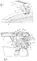
- a motor vehicle in the form of a passenger car has according to Fig. 1 a vehicle roof 1, which is provided at its opposite longitudinal sides, each with a roof rail profile 2.
- the two roof rails 2 extend substantially in the vehicle longitudinal direction over most of the length of the vehicle roof 1.
- a roof rack assembly which is provided for attachment to the two roof rails 2, has an elongated support section 3, which in the assembled state in the vehicle transverse direction across the width of the vehicle roof 1 extends.
- the carrier profile 3 is supported at its opposite Stirnend Schemeen by a respective support leg 4, which is mounted on the respective roof rail profile 2.
- Fig. 1 to 5 is only the - viewed in the normal direction of travel of the passenger car - left support leg 4 shown.
- the opposite support leg 4 is mirror-symmetrical, otherwise designed identically.
- the support leg 4 has a dimensionally stable support body 5 which supports the support profile 3 in the region of an underside of the support profile 3.
- a clamping jaw 7 is mounted to move linearly displaceable parallel to a longitudinal extension of the carrier profile 3.
- the jaws 7 is positioned in the assembled state of the carrier profile 3 on the inside of the roof rail profile 2.
- a clamping lever 11 is pivotally mounted, which is held at its base around a pivot axis 12 in the region of a bottom of the jaw 7 by means of a corresponding pivot bearing.
- the pivot axis 12 extends transversely to a longitudinal extent of the carrier profile 3 and thus in the basis of the Fig.
- the tensioning lever 11 has a head portion 13, which projects through a longitudinal slot in the carrier profile 3, not shown, into a hollow profile section 14, ie, into a cavity, of the carrier profile 3.
- the support elements 15, 16 are arranged.
- the support elements 15, 16 support the head section 13 in the hollow profile section 14 of the carrier profile 3 on both sides of the longitudinal slot in the region of the underside of the carrier profile 3.
- the support elements 15, 16 are pivotally mounted on the head portion 13 about axes of rotation, which are aligned parallel to the pivot axis 12.
- a bearing pin 17 is provided for rotatably supporting the block-like support elements 15, which flank the head portion 13 on both sides of the longitudinal slot of the carrier profile 3.
- the support elements 15 are also referred to as clamping blocks.
- the support member 16 is a tensioning element and is formed by a curved leaf spring, which is mounted by means of a carrier body and a bearing pin 18 on the head portion 13. Also, the support members 16 are arranged in pairs in an identical manner on both sides of the head portion 13. Both support elements 16 are designed identically to each other and each have a bent leaf spring, which are supported on the bottom of the hollow profile section 14 laterally adjacent to the longitudinal slot of the carrier profile 3. Design and function of the designed as clamping elements support elements 16 are based on the Fig. 6 described in more detail below.
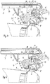
- Each support foot 4 also includes a clamping plate 8, which is positioned in the assembled state of the carrier profile 3 on the outside of the roof rail profile 2.
- the clamping plate 8 has a lower handle, which is designed as an inwardly curved web to engage under an outer shoulder of the roof rails profile 2 (see Fig. 3 to 5 ).
- the clamping plate 8 has on its upper side opposite the lower handle a guide portion 9, which is supported on the outside on a curved guide surface 10 of the support body 5.
- the clamping plate 8 is mounted relative to the support body 5 displaceable in the vertical direction substantially, wherein the guide portion 9 slides along the curved guide surface 10 of the support body 5.
- the clamping plate 8 is in a release position according to Fig.
- the inner jaw 7 is in its release position according to Fig. 2 spaced inwardly towards the center of the roof toward the inside of the roof rail profile 2, but is already on top of the top of the roof rails profile 2 on ( Fig. 2 . 3 and 6 ).
- the clamped state of the jaws 7 is displaced relative to the support body 5 linearly movable outwards to the roof rail profile 2, wherein a vertical supporting flank of the jaw 7 is pressed in accordance with an inner shoulder of the roof rail profile 2.
- an actuating unit 19, 20 which comprises a set screw 19 provided with a screw head.
- the adjusting screw 19 is screwed into a threaded receptacle of the clamping lever 11.
- the threaded receptacle is formed by a threaded nut 20, which is limited rotatably supported within the clamping lever 11 about an axis of rotation, which is aligned parallel to the pivot axis 12.
- pivotal movements of the adjusting screw 19, which occur during screwing or screwing can be compensated.
- the screw head of the adjusting screw 19 is supported on the outside on a corresponding contact surface of the clamping plate 8. Due to the fact that the threaded nut 20 in the Tensioning lever 11 is mounted, the adjusting screw 19 is also in operative connection with the clamping lever 11.
- the adjusting screw 19 is tightened by means of a torque wrench to a predetermined torque, which ensures that the support body 5 is securely clamped on the jaws 7 and the clamping lever 11 with the carrier profile 3.
- a torque wrench to a predetermined torque, which ensures that the support body 5 is securely clamped on the jaws 7 and the clamping lever 11 with the carrier profile 3.
- the accessibility of the adjusting screw 19 on the support body 5 is closed by a hinged cover panel 6, which is additionally provided with a lock to in the closed state of the cover panel 6 in accordance Fig. 5 to prevent opening the lid panel 6.
- the set Montageklemmung is secured by the actuator.
- a disassembly of the roof rack assembly is carried out in accordance with the reverse manner by loosening and opening the cover plate 6 and by screwing the screw 19, whereby the clamping plate 8 and the jaws 7 inevitably perform opposite movements in the direction of their release position. After reaching the release position, the roof rack assembly can be removed in a simple manner from the roof rail profiles 2 and thus from the vehicle roof 1.
- the two designed as leaf springs support members 16 flanking the head portion 13 on opposite sides and are supported on a bottom portion 21 of the hollow profile section 14 of the support section 3 are connected to each other via the bearing pin 18 which penetrates a bore of the head portion 13.
- the bearing pin 18 is designed as a blind rivet.
- Corresponding tab portions of the leaf springs 16, which together form the blind rivets, are integral with the spring steel of the respective leaf spring.
- Both leaf springs 16 are designed in W-shaped cross-sectional configuration (see Fig. 6 ) and have two downwardly projecting, hump-shaped support portions 22, by means of which each leaf spring 16 is supported on the bottom portion 21 of the hollow profile section 14 laterally adjacent to the longitudinal slot in the bottom portion of the carrier profile.
Landscapes
- Engineering & Computer Science (AREA)
- Mechanical Engineering (AREA)
- Fittings On The Vehicle Exterior For Carrying Loads, And Devices For Holding Or Mounting Articles (AREA)
Description
Die Erfindung betrifft eine Dachträgeranordnung für ein Kraftfahrzeug mit einem Trägerprofil, das in montiertem Zustand in Fahrzeugquerrichtung über ein Fahrzeugdach erstreckt ist, sowie mit zwei Stützfüßen, die das Trägerprofil in montiertem Zustand auf jeweils einem fahrzeugfesten Dachrelingprofil sichern, wobei jeder Stützfuß einen Stützkörper, auf dem das Trägerprofil abgestützt ist, sowie einen relativ zu dem Stützkörper beweglichen inneren Klemmbacken aufweist.The invention relates to a roof carrier assembly for a motor vehicle with a carrier profile which extends in the vehicle transverse direction over a vehicle roof in the assembled state, and with two support legs which secure the carrier profile in the assembled state on each vehicle-fixed roof rail profile, wherein each support leg a support body on the the carrier profile is supported, and has a relative to the support body movable inner jaws.
Eine derartige Dachträgeranordnung ist aus der
Diese Aufgabe wird dadurch gelöst, dass der innere Klemmbacken parallel zu einer Längserstreckung des Trägerprofils linearbeweglich gelagert ist, und dass eine mechanische Stelleinheit vorgesehen ist, die mit dem inneren Klemmbacken in Wirkverbindung ist, um den Klemmbacken zwischen einer Freigabestellung und einer Klemmstellung zu verlagern. In der Freigabestellung des Klemmbackens ist der Klemmbacken zu dem entsprechenden Dachrelingprofil beabstandet, so dass der Stützfuß nach oben von dem Dachrelingprofil entfernt werden kann. In der Klemmstellung wird der Klemmbacken von einer Innenseite her gegen das Dachrelingprofil gedrückt. Der innere Klemmbacken ist in montiertem Zustand der Dachträgeranordnung auf dem Fahrzeugdach auf einer zur Dachmitte hin gewandten Innenseite des entsprechenden Dachrelingprofils angeordnet. Die Stelleinheit, die erfindungsgemäß auf den inneren Klemmbacken wirkt, ermöglicht eine einfache Handhabung bei einer Montage oder Demontage der Dachträgeranordnung. Dadurch, dass der innere Klemmbacken relativ zu dem Stützkörper des Stützfußes beweglich angeordnet ist, kann der Stützkörper selbst kompakt gestaltet sein. Erfindungsgemäß weist jeder Stützfuß eine äußere Klemmplatte mit einem Untergriff auf, die in Hochrichtung relativ zu dem Stützkörper verlagerbar ist, und die mechanische Stelleinheit ist zusätzlich mit der äußeren Klemmplatte in Wirkverbindung, um die Klemmplatte gemeinsam mit dem Klemmbacken zwischen der Freigabestellung und der Klemmstellung zu verlagern. Der Untergriff der Klemmplatte dient dazu, ein entsprechendes Dachrelingprofil eines Fahrzeugdachs außenseitig zu untergreifen. In der Klemmstellung untergreift die Klemmplatte das Dachrelingprofil außenseitig klemmend. Die äußere Klemmplatte ist in diesem montierten Zustand auf einer zur Fahrzeugaußenseite gewandten äußeren Flanke des jeweiligen Dachrelingprofils positioniert. Die Verlagerbarkeit der äußeren Klemmplatte in Hochrichtung bedeutet, dass die Klemmplatte eine Bewegungskomponente in Hochrichtung durchführt, die von anderen Bewegungskomponenten in Quer- oder Längsrichtung relativ zum Stützkörper überlagert sein kann. Erfindungsgemäß ist die Klemmplatte in Abstand oberhalb des Untergriffs mit einem Führungsabschnitt versehen, der auf einer gekrümmten Führungsfläche des Stützkörpers gleitbeweglich abgestützt ist. Die gekrümmte Führungsfläche des Stützkörpers ist auf einer Außenseite des Stützkörpers vorgesehen, die in montiertem Zustand in Fahrzeugquerrichtung zur Außenseite des Fahrzeugs hin gewandt ist.This object is achieved in that the inner jaw is mounted linearly movable parallel to a longitudinal extension of the carrier profile, and that a mechanical actuator is provided which is in operative connection with the inner jaws to move the jaws between a release position and a clamping position. In the release position of the jaw of the jaws is spaced from the corresponding roof rail profile, so that the support leg can be removed upwards from the roof rails profile. In the clamping position of the jaws is pressed from an inner side against the roof rails profile. The inner jaw is arranged in the mounted state of the roof rack assembly on the vehicle roof on a side facing the roof center inside of the corresponding roof rail profile. The actuator, which acts according to the invention on the inner jaws, allows easy handling during assembly or disassembly of the roof rack assembly. Characterized in that the inner jaw is arranged to be movable relative to the support body of the support leg, the support body itself can be made compact. According to the invention, each support leg has an outer clamping plate with a lower handle, which is displaceable in the vertical direction relative to the support body, and the mechanical actuator is in addition to the outer clamping plate in operative connection to move the clamping plate together with the jaw between the release position and the clamping position , The lower grip of the clamping plate serves to engage under the exterior of a corresponding roof rail profile of a vehicle roof. In the clamping position, the clamping plate engages below the roof rail profile clamping on the outside. The outer clamping plate is positioned in this mounted state on an outer side facing the vehicle outer edge of the respective roof rail profile. The displaceability of the outer clamping plate in the vertical direction means that the clamping plate performs a movement component in the vertical direction, which may be superposed by other components of movement in the transverse or longitudinal direction relative to the support body. According to the invention, the clamping plate is provided at a distance above the lower handle with a guide section which is slidably supported on a curved guide surface of the support body. The curved guide surface of the support body is provided on an outer side of the support body, which is turned in the mounted state in the vehicle transverse direction to the outside of the vehicle.
In weiterer Ausgestaltung der Erfindung umfasst die Stelleinheit einen Spannhebel, der in dem linearbeweglichen Klemmbacken schwenkbeweglich gelagert ist, und der einen Kopfabschnitt umfasst, der formschlüssig in das Trägerprofil eingreift. Der Spannhebel ist demzufolge am linearbeweglichen Klemmbacken abgestützt und über seinen Kopfabschnitt in einem entsprechenden Hohlprofilbereich des Trägerprofils gehalten.In a further embodiment of the invention, the adjusting unit comprises a clamping lever, which is pivotally mounted in the linearly movable clamping jaws, and which comprises a head portion which engages positively in the carrier profile. The tensioning lever is therefore supported on the linearly movable clamping jaws and held over its head portion in a corresponding hollow profile region of the carrier profile.
In weiterer Ausgestaltung der Erfindung weist der Kopfabschnitt Stützelemente auf, die in dem Trägerprofil längsverlagerbar geführt sind, und die den Kopfabschnitt in Hochrichtung in dem Trägerprofil abstützen. Diese Ausgestaltung ist vorteilhaft, damit der Spannhebel gemeinsam mit dem linearbeweglichen Klemmbacken relativ zum Trägerprofil verschoben werden kann.In a further embodiment of the invention, the head portion on supporting elements, which are guided longitudinally displaceable in the carrier profile, and which support the head portion in the vertical direction in the carrier profile. This embodiment is advantageous so that the clamping lever can be moved together with the linearly movable clamping jaws relative to the carrier profile.
In weiterer Ausgestaltung der Erfindung sind die Stützelemente an dem Kopfabschnitt um wenigstens eine Gelenkachse gelenkig gelagert, die parallel zu der Schwenkachse des Spannhebels ausgerichtet ist. Diese Ausgestaltung ist vorteilhaft, wenn die Schwenkbeweglichkeit des Spannhebels zusätzlich dazu führt, den Stützkörper von unten her gegen das Trägerprofil zu pressen. Denn dann führt der Spannhebel mittels seines Kopfabschnitts innerhalb des Trägerprofils leichte Schwenkbewegungen durch, die durch die gelenkige Lagerung der Gleitelemente ausgeglichen werden, die im Trägerprofil linearbeweglich gelagert sind.In a further embodiment of the invention, the support elements are articulated to the head portion about at least one hinge axis, which is aligned parallel to the pivot axis of the clamping lever. This embodiment is advantageous if the pivoting movement of the clamping lever additionally leads to press the support body from below against the carrier profile. Because then performs the clamping lever by means of its head portion within the carrier profile slight pivotal movements, which are compensated by the articulated mounting of the sliding elements, which are mounted linearly movable in the carrier profile.
In weiterer Ausgestaltung der Erfindung weist die Stelleinheit eine von einer Außenseite des Stützfußes her zugängliche Stellschraube auf, die mittels ihres Schraubenkopfes an der Klemmplatte abgestützt ist, und die in eine Gewindeaufnahme des Spannhebels schraubbeweglich eingreift. Dadurch wird mit einfachen Mitteln die Wirkverbindung zwischen der Stelleinheit, der Klemmplatte und dem Klemmbacken, d.h. dem Spannhebel, erzielt.In a further embodiment of the invention, the actuating unit has an adjustable from an outer side of the support foot forth adjusting screw, which is supported by means of its screw head on the clamping plate, and engages in a threaded receiving the clamping lever schraubbeweglich. Thereby, by simple means, the operative connection between the actuator, the clamping plate and the jaws, i. the clamping lever achieved.
In weiterer Ausgestaltung der Erfindung ist die Gewindeaufnahme durch eine Gewindemutter gebildet, die in dem Spannhebel um eine Drehachse begrenzt drehbeweglich gelagert ist, die parallel zu der Schwenkachse des Spannhebels ausgerichtet ist. Dadurch werden relative Drehbewegungen zwischen der Stellschraube der Stelleinheit und dem Spannhebel während eines entsprechenden Montage- oder Demontagevorgangs ausgeglichen.In a further embodiment of the invention, the threaded receptacle is formed by a threaded nut which is limited in the clamping lever about an axis of rotation rotatably mounted, which is aligned parallel to the pivot axis of the clamping lever. As a result, relative rotational movements between the adjusting screw of the adjusting unit and the clamping lever during a corresponding assembly or disassembly operation are compensated.
In weiterer Ausgestaltung der Erfindung ist wenigstens ein Stützelement durch ein in Hochrichtung elastisch nachgiebiges Spannelement gebildet, das sich in Hochrichtung vorgespannt auf einem Bodenabschnitt des Trägerprofils abstützt. Durch die Abstützung des Spannelementes auf dem Bodenabschnitt des Trägerprofils bewirkt das Spannelement eine Zugkraft in Hochrichtung auf den Kopfabschnitt des Spannhebels. Die elastische Nachgiebigkeit ermöglicht eine Klapperfreiheit des Stützfußes relativ zum Trägerprofil in unmontiertem Zustand des Trägerprofils. Zudem ist ein Toleranzausgleich zwischen Trägerprofil und Stützfuß bzw. zwischen Trägerprofil und Kopfabschnitt des Spannhebels gewährleistet. Als elastisch nachgiebiges Spannelement kann eine Elastomeranordnung oder eine Federanordnung vorgesehen sein.In a further embodiment of the invention, at least one support element is formed by a resiliently elastic in the vertical direction clamping element, which is biased in the vertical direction supported on a bottom portion of the carrier profile. By supporting the clamping element on the bottom portion of the carrier profile, the clamping element causes a tensile force in the vertical direction on the head portion of the clamping lever. The elastic compliance allows a rattle of the support leg relative to the carrier profile in the unmounted state of the carrier profile. In addition, a tolerance compensation between the carrier profile and support leg or between the carrier profile and the head portion of the clamping lever is guaranteed. As an elastically resilient clamping element may be provided an elastomeric arrangement or a spring arrangement.
In weiterer Ausgestaltung der Erfindung ist das Spannelement durch eine Blattfeder gebildet, die zwei in Längsrichtung des Trägerprofils zueinander beabstandete Stützabschnitte aufweist, mit denen die Blattfeder auf dem Bodenabschnitt des Trägerprofils abgestützt ist. Die Blattfeder weist demzufolge eine im Querschnitt W-artige Form auf. Durch die zueinander beabstandeten Stützabschnitte ist eine statisch bestimmte Abstützung des Kopfabschnittes in dem Trägerprofil durch die wenigstens eine Blattfeder gewährleistet. In vorteilhafter Weise liegt die Gelenkachse der Blattfeder, um die die Blattfeder relativ zum Kopfabschnitt schwenkbeweglich gelagert ist, in einer vertikalen Mittelebene zwischen den beiden Stützabschnitten.In a further embodiment of the invention, the clamping element is formed by a leaf spring having two spaced apart in the longitudinal direction of the carrier profile support portions with which the leaf spring is supported on the bottom portion of the carrier profile. The leaf spring therefore has a cross-section W-like shape. By the mutually spaced support portions a statically determined support of the head portion in the support profile is ensured by the at least one leaf spring. Advantageously, the hinge axis of the leaf spring, around which the leaf spring is mounted pivotably relative to the head portion, in a vertical center plane between the two support portions.
In weiterer Ausgestaltung der Erfindung ist eine in Längsrichtung des Trägerprofils zu dem wenigstens einen Spannelement beabstandetes, um eine parallele Gelenkachse am Kopfabschnitt schwenkbeweglich angelenktes Stützelement vorgesehen, das in unbelastetem Zustand des Spannhebels zu dem Bodenabschnitt des Trägerprofils beabstandet ist. Das Stützelement wird somit während eines Verlagerungsvorganges des Klemmbackens gemeinsam mit dem Spannhebel durch das wenigstens eine Spannelement zunächst in einer knapp über dem Bodenabschnitt des Trägerprofils schwebenden Stellung gehalten, bevor der Spannhebel beim Auftreffen und Klemmen des Klemmbackens relativ zum Dachrelingprofil zu kippen beginnt. Das Spannelement hält den Spannhebel somit in etwa vertikaler Ausrichtung, wobei das Stützelement erst ab einem vorgegebenen, höheren Drehmoment, das durch die Stelleinheit auf den Spannhebel wirkt, in Eingriff mit dem Trägerprofil gelangt. Als Stützelement ist vorzugsweise ein Klemmstein vorgesehen, der quaderartig ausgeführt ist und vorzugsweise Kunststoffgleitflächen aufweist, mit denen das Stützelement an dem Bodenabschnitt oder an einer anderen Wandungsfläche des Trägerprofils zur Anlage gelangt.In a further embodiment of the invention, a spaced in the longitudinal direction of the carrier profile to the at least one clamping element to a parallel hinge axis at the head portion pivotally articulated support member is provided, which is spaced in the unloaded state of the clamping lever to the bottom portion of the carrier profile. The support element is thus during a displacement process of the jaw together with the clamping lever by the at least one tensioning element initially in a just above the bottom portion held the carrier profile floating position before the clamping lever begins to tilt when hitting and clamping of the jaw relative to the roof rails profile. The clamping element thus holds the clamping lever in approximately vertical orientation, wherein the support element only comes into engagement with the carrier profile from a predetermined, higher torque which acts on the clamping lever by the setting unit. As a support member preferably a clamping block is provided, which is executed like a cuboid and preferably has plastic sliding surfaces with which the support element comes to rest on the bottom portion or on another wall surface of the support profile.
In weiterer Ausgestaltung der Erfindung ist eine Vorspannkraft, die durch das wenigstens eine Spannelement auf den Bodenabschnitt des Trägerprofils wirkt, derart dimensioniert, dass der Kopfabschnitt bei einer Verlagerungsbewegung des Klemmbackens durch das Spannelement derart parallel gehalten wird, dass das Stützelement zu dem Bodenabschnitt beabstandet bleibt, bis der Klemmbacken an dem Dachrelingprofil zur Anlage kommt und der Spannhebel um einen vorgegebenen Winkel verschwenkt ist. Durch das wenigstens eine Spannelement wird auf den Bodenabschnitt des Trägerprofils in Hochrichtung des Spannhebels in jeder Montagestellung eine Stützkraft übertragen, die den Kopfabschnitt in Hochrichtung in den Längsschlitz des Trägerprofils hineinzieht. Diese permanent vorhandene Vorspannkraft wird bei einer Verschwenkung des Spannhebels überlagert durch die zusätzlich auftretende Klemmkraft in Hochrichtung nach unten, mit der das vorzugsweise als Klemmstein ausgeführte Spannelement auf den Bodenabschnitt des Trägerprofils gepresst wird.In a further embodiment of the invention, a biasing force acting through the at least one tensioning element on the bottom portion of the carrier profile, dimensioned such that the head portion is held parallel to a displacement movement of the jaw by the tensioning element, that the support element remains spaced from the bottom portion, until the jaw comes to rest on the roof rails profile and the clamping lever is pivoted by a predetermined angle. By the at least one clamping element, a supporting force is transmitted to the bottom portion of the carrier profile in the vertical direction of the clamping lever in each mounting position, which pulls the head portion in the vertical direction in the longitudinal slot of the carrier profile. This permanently existing biasing force is superimposed upon pivoting of the clamping lever by the additionally occurring clamping force in the vertical direction downwards, with which the preferably designed as a clamping block clamping element is pressed onto the bottom portion of the carrier profile.
Weitere Vorteile und Merkmale der Erfindung ergeben sich aus den Ansprüchen sowie aus der nachfolgenden Beschreibung eines bevorzugten Ausführungsbeispiels der Erfindung, das anhand der Zeichnungen dargestellt ist.
- Fig. 1
- zeigt in perspektivischer Darstellung einen Ausschnitt einer Ausführungsform einer erfindungsgemäßen Dachträgeranordnung in montiertem Zustand auf einem Dachrelingprofil eines Fahrzeugdachs,
- Fig. 2
- die Ausführungsform nach
Fig. 1 in einer Schnittdarstellung längs einer vertikalen Fahrzeugquerebene, - Fig. 3
- die Dachträgeranordnung nach
Fig. 2 in einer Zwischenmontagestellung, - Fig. 4
- die Dachträgeranordnung nach den
Fig. 2 und3 in einer an dem Dachrelingprofil geklemmten Montageposition, - Fig. 5
- die Dachträgeranordnung nach
Fig. 4 mit verschlossenem Blendendeckel und - Fig. 6
- in vergrößerter Darstellung den Schnitt gemäß
Fig. 2 .
- Fig. 1
- shows a perspective view of a detail of an embodiment of a roof carrier assembly according to the invention in the assembled state on a roof rails profile of a vehicle roof,
- Fig. 2
- the embodiment according to
Fig. 1 in a sectional view along a vertical vehicle transverse plane, - Fig. 3
- the roof rack assembly according to
Fig. 2 in an intermediate assembly position, - Fig. 4
- the roof rack assembly according to
Fig. 2 and3 in a mounting position clamped to the roof rails profile, - Fig. 5
- the roof rack assembly according to
Fig. 4 with closed cover and - Fig. 6
- in an enlarged view the section according to
Fig. 2 ,
Ein Kraftfahrzeug in Form eines Personenkraftwagens weist gemäß
Der Stützfuß 4 weist einen formstabilen Stützkörper 5 auf, der das Trägerprofil 3 im Bereich einer Unterseite des Trägerprofils 3 abstützt. Im Bereich einer Unterseite des Stützkörpers 5 ist ein Klemmbacken 7 parallel zu einer Längserstreckung des Trägerprofils 3 linearbeweglich verschiebbar gelagert. Der Klemmbacken 7 ist in montiertem Zustand des Trägerprofils 3 innenseitig des Dachrelingprofils 2 positioniert. In dem Klemmbacken 7 ist ein Spannhebel 11 schwenkbeweglich gelagert, der an seinem Fußbereich um eine Schwenkachse 12 im Bereich eines Bodens des Klemmbackens 7 mittels einer entsprechenden Schwenklagerung gehalten ist. Die Schwenkachse 12 erstreckt sich quer zu einer Längserstreckung des Trägerprofils 3 und damit in dem anhand der
Jeder Stützfuß 4 umfasst zudem eine Klemmplatte 8, die in montiertem Zustand des Trägerprofils 3 außenseitig des Dachrelingprofils 2 positioniert ist. Die Klemmplatte 8 weist einen Untergriff auf, der als nach innen gekrümmter Steg ausgeführt ist, um eine Außenschulter des Dachrelingprofils 2 untergreifen zu können (siehe
Um den Klemmbacken 7 und die Klemmplatte 8 zwischen der Freigabestellung und der Klemmstellung verlagern zu können, ist eine Stelleinheit 19, 20 vorgesehen, die eine mit einem Schraubenkopf versehene Stellschraube 19 umfasst. Die Stellschraube 19 ist in eine Gewindeaufnahme des Spannhebels 11 einschraubt. Die Gewindeaufnahme wird durch eine Gewindemutter 20 gebildet, die innerhalb des Spannhebels 11 begrenzt drehbeweglich um eine Drehachse gelagert ist, die parallel zur Schwenkachse 12 ausgerichtet ist. Dadurch können Schwenkbewegungen der Stellschraube 19, die beim Auf- oder Zuschrauben auftreten, ausgeglichen werden. Der Schraubenkopf der Stellschraube 19 stützt sich außenseitig auf einer entsprechenden Anlagefläche der Klemmplatte 8 ab. Dadurch, dass die Gewindemutter 20 in dem Spannhebel 11 gelagert ist, steht die Stellschraube 19 auch mit dem Spannhebel 11 in Wirkverbindung.In order to be able to displace the clamping
Sobald die Stellschraube 19 aus der Freigabestellung gemäß
Eine Demontage der Dachträgeranordnung erfolgt in entsprechend umgekehrter Weise durch ein Lösen und Öffnen der Deckelblende 6 und durch ein Aufschrauben der Stellschraube 19, wodurch die Klemmplatte 8 und der Klemmbacken 7 zwangsläufig entgegengesetzte Bewegungen in Richtung ihrer Freigabestellung durchführen. Nach Erreichen der Freigabestellung kann die Dachträgeranordnung in einfacher Weise von den Dachrelingprofilen 2 und damit vom Fahrzeugdach 1 entfernt werden.A disassembly of the roof rack assembly is carried out in accordance with the reverse manner by loosening and opening the cover plate 6 and by screwing the
Die beiden als Blattfedern gestalteten Stützelemente 16, die den Kopfabschnitt 13 auf gegenüberliegenden Seiten flankieren und sich auf einem Bodenabschnitt 21 des Hohlprofilabschnitts 14 des Trägerprofils 3 abstützen, sind über den Lagerbolzen 18 miteinander verbunden, der eine Bohrung des Kopfabschnittes 13 durchdringt. Der Lagerbolzen 18 ist als Blindniet gestaltet. Entsprechende Laschenabschnitte der Blattfedern 16, die gemeinsam die Blindniete bilden, sind einstückig mit dem Federstahl der jeweiligen Blattfeder. Beide Blattfedern 16 sind in W-förmiger Querschnittsgestaltung ausgeführt (siehe
Claims (10)
- Roof rack assembly for a motor vehicle, comprising a rack profile (3) extending in the installed condition in the transverse direction of the vehicle across a vehicle roof (1), and comprising two leg supports (4) securing the rack profile (3) in the installed condition on a respective one of vehicle-fixed roof railing profiles (2), wherein each leg support (4) includes a support body (5) with the rack profile (3) supported thereon, and an inner clamping jaw (7) which is movable relative to the support body, wherein the inner clamping jaw (7) is mounted for linear movement in parallel to a longitudinal extension of the rack profile (3), and in that a mechanical actuator unit (11, 19, 20) is provided and in operative connection to the inner clamping jaw (7), in order to displace the clamping jaw (7) between a release position and a clamping position, characterized in that
each leg support (4) includes an outer clamping plate (8) with an undercut, which plate is displaceable in the vertical direction relative to the support body (5), and in that the mechanical actuator unit (11, 19, 20) is additionally in operative connection to the outer clamping plate (8), and in that the clamping plate (8) is provided with a guiding section (9) at a distance above the undercut, which guiding section is supported on a curved guiding surface (10) of the support body for sliding movement. - Roof rack assembly according to claim 1, characterized in that the actuator unit (11, 19, 20) comprises a tensioning lever (11) which is pivotably mounted in the linearly movable clamping jaw (7), and which includes a head section (13) engaging in the rack profile (3) in a form-fitting manner.
- Roof rack assembly according to claim 2, characterized in that the head section (13) includes support elements (15, 16) which are guided in the rack profile (3) for lengthwise displacement, and which support the head section (13) in the rack profile (3) in the vertical direction.
- Roof rack assembly according to claim 3, characterized in that the support elements (15, 16) are articulated to the head section (13) about at least one hinge axis which is oriented in parallel to the pivot axis of the tensioning lever (11).
- Roof rack assembly according to claim 4, characterized in that the actuator unit includes an adjuster screw (19) accessible from an exterior side of the leg support (4), which screw is supported on the clamping plate (8) by means of its screw head, and which screw engages in a threaded seat of the tensioning lever (11) by screwing.
- Roof rack assembly according to claim 5, characterized in that the threaded seat is a threaded nut (20) which is mounted in the tensioning lever (11) for rotation about a rotational axis in a limited manner, which rotational axis is oriented in parallel to the pivot axis of the tensioning lever (11).
- Roof rack assembly according to any of the preceding claims, characterized in that at least one support element is a tensioning element (16) elastically resilient in the vertical direction, which element is supported on a bottom section (21) of the rack profile (3) pre-tensioned in the vertical direction.
- Roof rack assembly according to claim 7, characterized in that the tensioning element (16) is a leaf spring which includes two support sections (22) mutually spaced in the longitudinal direction of the rack profile (3), with the leaf spring being supported on the bottom section (21) of the rack profile (3) by said support sections.
- Roof rack assembly according to claim 7 or 8, characterized in that a support element (15) spaced from the at least one tensioning element (16) in the longitudinal direction of the rack profile (3), pivotably articulated on the head section (13) about a parallel hinge axis is provided, which support element is spaced from the bottom section (21) of the rack profile (3) in the unloaded condition of the tensioning lever (11).
- Roof rack assembly according to claim 9, characterized in that a pre-tensioning force acting on the bottom section (21) of the rack profile (3) via the at least one tensioning element (16) is dimensioned such that the head section (13) during a displacing move of the clamping jaw (7) is held in parallel by the tensioning element (16) in such a manner that the support element (15) remains spaced from the bottom section (21) until the clamping jaw (7) comes to abutment on the roof railing profile (2) and the tensioning lever (11) is pivoted about a pre-defined angle.
Priority Applications (1)
| Application Number | Priority Date | Filing Date | Title |
|---|---|---|---|
| PL15179626T PL2995502T3 (en) | 2014-09-11 | 2015-08-04 | Roof rack assembly for a motor vehicle |
Applications Claiming Priority (1)
| Application Number | Priority Date | Filing Date | Title |
|---|---|---|---|
| DE102014218227.1A DE102014218227A1 (en) | 2014-09-11 | 2014-09-11 | Roof rack assembly for a motor vehicle |
Publications (2)
| Publication Number | Publication Date |
|---|---|
| EP2995502A1 EP2995502A1 (en) | 2016-03-16 |
| EP2995502B1 true EP2995502B1 (en) | 2017-10-18 |
Family
ID=53783109
Family Applications (1)
| Application Number | Title | Priority Date | Filing Date |
|---|---|---|---|
| EP15179626.5A Active EP2995502B1 (en) | 2014-09-11 | 2015-08-04 | Roof rack assembly for a motor vehicle |
Country Status (3)
| Country | Link |
|---|---|
| EP (1) | EP2995502B1 (en) |
| DE (1) | DE102014218227A1 (en) |
| PL (1) | PL2995502T3 (en) |
Families Citing this family (2)
| Publication number | Priority date | Publication date | Assignee | Title |
|---|---|---|---|---|
| EP3594065B1 (en) | 2018-07-13 | 2020-11-04 | Thule Sweden AB | Load carrier |
| CN112483439B (en) * | 2020-11-13 | 2022-07-22 | 绍兴上虞上立风机有限公司 | High-pressure fan |
Family Cites Families (5)
| Publication number | Priority date | Publication date | Assignee | Title |
|---|---|---|---|---|
| JPH0238158A (en) * | 1988-07-29 | 1990-02-07 | Kokusan Kinzoku Kogyo Co Ltd | Roof carrier for vehicle |
| US6112965A (en) * | 1996-09-10 | 2000-09-05 | Industri Ab Thule | Railing bracket |
| AU2003231688A1 (en) | 2003-01-31 | 2004-08-19 | Roof Rack Industries Pty Ltd | Rail Bar Roof Rack |
| EP2303641B1 (en) * | 2008-06-23 | 2012-11-28 | Yakima Products, Inc. | Rack tower for securing crossbars on top of a vehicle |
| DE102011053603A1 (en) * | 2011-09-14 | 2013-03-14 | Jac Products Europe Gmbh | Roof rack for motor vehicles |
-
2014
- 2014-09-11 DE DE102014218227.1A patent/DE102014218227A1/en not_active Ceased
-
2015
- 2015-08-04 EP EP15179626.5A patent/EP2995502B1/en active Active
- 2015-08-04 PL PL15179626T patent/PL2995502T3/en unknown
Non-Patent Citations (1)
| Title |
|---|
| None * |
Also Published As
| Publication number | Publication date |
|---|---|
| EP2995502A1 (en) | 2016-03-16 |
| PL2995502T3 (en) | 2018-04-30 |
| DE102014218227A1 (en) | 2016-03-17 |
Similar Documents
| Publication | Publication Date | Title |
|---|---|---|
| EP3556978A1 (en) | Device for moving a piece of furniture on a body of a piece of furniture | |
| DE102008007094A1 (en) | Locking device for longitudinal- and/or elevational adjustable steering column of motor vehicle, has guiding surface arranged in recess of engaging element, whose longitudinal extension lies in plane parallel to positive-fit plane | |
| DE202017100971U1 (en) | Mounting device for inserting frame elements in wall openings | |
| EP3085581A1 (en) | Rear carrier system for a motor vehicle | |
| EP1544379B1 (en) | Clamping device | |
| EP2995502B1 (en) | Roof rack assembly for a motor vehicle | |
| DE202011051957U1 (en) | Door retainers for motor vehicles | |
| EP2672045B1 (en) | Guide assembly of a sliding door of a piece of furniture with a sliding door | |
| EP2792830B1 (en) | Fitting element mit retaining element for holding said fitting element | |
| DE3941937A1 (en) | Shuttering-section locking clamp - has lever with logarithmic spiral cam on moving jaw housing | |
| DE9307599U1 (en) | Window regulators, especially for convertible vehicles | |
| DE102014206719B4 (en) | Roof rack assembly for a motor vehicle | |
| DE102007034432B4 (en) | Shuttering element for circular formwork | |
| EP1190906A2 (en) | Fastening device, especially for a roof box | |
| DE102014207832B4 (en) | Roof rack assembly for a motor vehicle | |
| DE202016103609U1 (en) | Adapter for mounting on a fixed point of a vehicle | |
| DE3718840C1 (en) | Window lifter for motor vehicles | |
| DE1922749B2 (en) | Device for fastening a printing plate on the forme cylinder of a printing machine | |
| EP3842373A1 (en) | Elevator rail system for easy installation | |
| EP3029241A1 (en) | Corner fitting with increased clamping force | |
| DE202006001611U1 (en) | Swiveling securing device for use between two vehicle parts that can move relative to each other has spring latch that interacts with longitudinal slot, forms guide gap with long side of slot | |
| DE10301584B4 (en) | Device for the displaceable arrangement of a panel | |
| EP3568549B1 (en) | Device for securing a pivotable element | |
| DE2343507C3 (en) | Hinge joint for windows, doors etc. | |
| DE10030325C2 (en) | slide |
Legal Events
| Date | Code | Title | Description |
|---|---|---|---|
| PUAI | Public reference made under article 153(3) epc to a published international application that has entered the european phase |
Free format text: ORIGINAL CODE: 0009012 |
|
| AK | Designated contracting states |
Kind code of ref document: A1 Designated state(s): AL AT BE BG CH CY CZ DE DK EE ES FI FR GB GR HR HU IE IS IT LI LT LU LV MC MK MT NL NO PL PT RO RS SE SI SK SM TR |
|
| AX | Request for extension of the european patent |
Extension state: BA ME |
|
| RIN1 | Information on inventor provided before grant (corrected) |
Inventor name: PICKL, ADOLF |
|
| 17P | Request for examination filed |
Effective date: 20160913 |
|
| RBV | Designated contracting states (corrected) |
Designated state(s): AL AT BE BG CH CY CZ DE DK EE ES FI FR GB GR HR HU IE IS IT LI LT LU LV MC MK MT NL NO PL PT RO RS SE SI SK SM TR |
|
| GRAP | Despatch of communication of intention to grant a patent |
Free format text: ORIGINAL CODE: EPIDOSNIGR1 |
|
| RIC1 | Information provided on ipc code assigned before grant |
Ipc: B60R 9/058 20060101ALI20170425BHEP Ipc: B60R 9/045 20060101AFI20170425BHEP |
|
| INTG | Intention to grant announced |
Effective date: 20170511 |
|
| GRAS | Grant fee paid |
Free format text: ORIGINAL CODE: EPIDOSNIGR3 |
|
| GRAA | (expected) grant |
Free format text: ORIGINAL CODE: 0009210 |
|
| AK | Designated contracting states |
Kind code of ref document: B1 Designated state(s): AL AT BE BG CH CY CZ DE DK EE ES FI FR GB GR HR HU IE IS IT LI LT LU LV MC MK MT NL NO PL PT RO RS SE SI SK SM TR |
|
| REG | Reference to a national code |
Ref country code: GB Ref legal event code: FG4D Free format text: NOT ENGLISH |
|
| REG | Reference to a national code |
Ref country code: CH Ref legal event code: EP |
|
| REG | Reference to a national code |
Ref country code: AT Ref legal event code: REF Ref document number: 937626 Country of ref document: AT Kind code of ref document: T Effective date: 20171115 Ref country code: IE Ref legal event code: FG4D Free format text: LANGUAGE OF EP DOCUMENT: GERMAN |
|
| REG | Reference to a national code |
Ref country code: DE Ref legal event code: R096 Ref document number: 502015002127 Country of ref document: DE |
|
| REG | Reference to a national code |
Ref country code: NL Ref legal event code: FP |
|
| REG | Reference to a national code |
Ref country code: SE Ref legal event code: TRGR |
|
| REG | Reference to a national code |
Ref country code: LT Ref legal event code: MG4D |
|
| PG25 | Lapsed in a contracting state [announced via postgrant information from national office to epo] |
Ref country code: ES Free format text: LAPSE BECAUSE OF FAILURE TO SUBMIT A TRANSLATION OF THE DESCRIPTION OR TO PAY THE FEE WITHIN THE PRESCRIBED TIME-LIMIT Effective date: 20171018 Ref country code: LT Free format text: LAPSE BECAUSE OF FAILURE TO SUBMIT A TRANSLATION OF THE DESCRIPTION OR TO PAY THE FEE WITHIN THE PRESCRIBED TIME-LIMIT Effective date: 20171018 Ref country code: FI Free format text: LAPSE BECAUSE OF FAILURE TO SUBMIT A TRANSLATION OF THE DESCRIPTION OR TO PAY THE FEE WITHIN THE PRESCRIBED TIME-LIMIT Effective date: 20171018 Ref country code: NO Free format text: LAPSE BECAUSE OF FAILURE TO SUBMIT A TRANSLATION OF THE DESCRIPTION OR TO PAY THE FEE WITHIN THE PRESCRIBED TIME-LIMIT Effective date: 20180118 |
|
| PG25 | Lapsed in a contracting state [announced via postgrant information from national office to epo] |
Ref country code: IS Free format text: LAPSE BECAUSE OF FAILURE TO SUBMIT A TRANSLATION OF THE DESCRIPTION OR TO PAY THE FEE WITHIN THE PRESCRIBED TIME-LIMIT Effective date: 20180218 Ref country code: BG Free format text: LAPSE BECAUSE OF FAILURE TO SUBMIT A TRANSLATION OF THE DESCRIPTION OR TO PAY THE FEE WITHIN THE PRESCRIBED TIME-LIMIT Effective date: 20180118 Ref country code: LV Free format text: LAPSE BECAUSE OF FAILURE TO SUBMIT A TRANSLATION OF THE DESCRIPTION OR TO PAY THE FEE WITHIN THE PRESCRIBED TIME-LIMIT Effective date: 20171018 Ref country code: RS Free format text: LAPSE BECAUSE OF FAILURE TO SUBMIT A TRANSLATION OF THE DESCRIPTION OR TO PAY THE FEE WITHIN THE PRESCRIBED TIME-LIMIT Effective date: 20171018 Ref country code: GR Free format text: LAPSE BECAUSE OF FAILURE TO SUBMIT A TRANSLATION OF THE DESCRIPTION OR TO PAY THE FEE WITHIN THE PRESCRIBED TIME-LIMIT Effective date: 20180119 Ref country code: HR Free format text: LAPSE BECAUSE OF FAILURE TO SUBMIT A TRANSLATION OF THE DESCRIPTION OR TO PAY THE FEE WITHIN THE PRESCRIBED TIME-LIMIT Effective date: 20171018 |
|
| REG | Reference to a national code |
Ref country code: DE Ref legal event code: R097 Ref document number: 502015002127 Country of ref document: DE |
|
| PG25 | Lapsed in a contracting state [announced via postgrant information from national office to epo] |
Ref country code: CZ Free format text: LAPSE BECAUSE OF FAILURE TO SUBMIT A TRANSLATION OF THE DESCRIPTION OR TO PAY THE FEE WITHIN THE PRESCRIBED TIME-LIMIT Effective date: 20171018 Ref country code: SK Free format text: LAPSE BECAUSE OF FAILURE TO SUBMIT A TRANSLATION OF THE DESCRIPTION OR TO PAY THE FEE WITHIN THE PRESCRIBED TIME-LIMIT Effective date: 20171018 Ref country code: DK Free format text: LAPSE BECAUSE OF FAILURE TO SUBMIT A TRANSLATION OF THE DESCRIPTION OR TO PAY THE FEE WITHIN THE PRESCRIBED TIME-LIMIT Effective date: 20171018 Ref country code: EE Free format text: LAPSE BECAUSE OF FAILURE TO SUBMIT A TRANSLATION OF THE DESCRIPTION OR TO PAY THE FEE WITHIN THE PRESCRIBED TIME-LIMIT Effective date: 20171018 |
|
| PLBE | No opposition filed within time limit |
Free format text: ORIGINAL CODE: 0009261 |
|
| REG | Reference to a national code |
Ref country code: FR Ref legal event code: PLFP Year of fee payment: 4 |
|
| STAA | Information on the status of an ep patent application or granted ep patent |
Free format text: STATUS: NO OPPOSITION FILED WITHIN TIME LIMIT |
|
| PG25 | Lapsed in a contracting state [announced via postgrant information from national office to epo] |
Ref country code: RO Free format text: LAPSE BECAUSE OF FAILURE TO SUBMIT A TRANSLATION OF THE DESCRIPTION OR TO PAY THE FEE WITHIN THE PRESCRIBED TIME-LIMIT Effective date: 20171018 Ref country code: SM Free format text: LAPSE BECAUSE OF FAILURE TO SUBMIT A TRANSLATION OF THE DESCRIPTION OR TO PAY THE FEE WITHIN THE PRESCRIBED TIME-LIMIT Effective date: 20171018 Ref country code: IT Free format text: LAPSE BECAUSE OF FAILURE TO SUBMIT A TRANSLATION OF THE DESCRIPTION OR TO PAY THE FEE WITHIN THE PRESCRIBED TIME-LIMIT Effective date: 20171018 |
|
| 26N | No opposition filed |
Effective date: 20180719 |
|
| PG25 | Lapsed in a contracting state [announced via postgrant information from national office to epo] |
Ref country code: MT Free format text: LAPSE BECAUSE OF FAILURE TO SUBMIT A TRANSLATION OF THE DESCRIPTION OR TO PAY THE FEE WITHIN THE PRESCRIBED TIME-LIMIT Effective date: 20171018 |
|
| PG25 | Lapsed in a contracting state [announced via postgrant information from national office to epo] |
Ref country code: SI Free format text: LAPSE BECAUSE OF FAILURE TO SUBMIT A TRANSLATION OF THE DESCRIPTION OR TO PAY THE FEE WITHIN THE PRESCRIBED TIME-LIMIT Effective date: 20171018 |
|
| PG25 | Lapsed in a contracting state [announced via postgrant information from national office to epo] |
Ref country code: MC Free format text: LAPSE BECAUSE OF FAILURE TO SUBMIT A TRANSLATION OF THE DESCRIPTION OR TO PAY THE FEE WITHIN THE PRESCRIBED TIME-LIMIT Effective date: 20171018 |
|
| REG | Reference to a national code |
Ref country code: CH Ref legal event code: PL |
|
| PG25 | Lapsed in a contracting state [announced via postgrant information from national office to epo] |
Ref country code: LI Free format text: LAPSE BECAUSE OF NON-PAYMENT OF DUE FEES Effective date: 20180831 Ref country code: CH Free format text: LAPSE BECAUSE OF NON-PAYMENT OF DUE FEES Effective date: 20180831 |
|
| REG | Reference to a national code |
Ref country code: IE Ref legal event code: MM4A |
|
| PG25 | Lapsed in a contracting state [announced via postgrant information from national office to epo] |
Ref country code: IE Free format text: LAPSE BECAUSE OF NON-PAYMENT OF DUE FEES Effective date: 20180804 |
|
| PG25 | Lapsed in a contracting state [announced via postgrant information from national office to epo] |
Ref country code: TR Free format text: LAPSE BECAUSE OF FAILURE TO SUBMIT A TRANSLATION OF THE DESCRIPTION OR TO PAY THE FEE WITHIN THE PRESCRIBED TIME-LIMIT Effective date: 20171018 |
|
| PG25 | Lapsed in a contracting state [announced via postgrant information from national office to epo] |
Ref country code: PT Free format text: LAPSE BECAUSE OF FAILURE TO SUBMIT A TRANSLATION OF THE DESCRIPTION OR TO PAY THE FEE WITHIN THE PRESCRIBED TIME-LIMIT Effective date: 20171018 |
|
| PG25 | Lapsed in a contracting state [announced via postgrant information from national office to epo] |
Ref country code: CY Free format text: LAPSE BECAUSE OF FAILURE TO SUBMIT A TRANSLATION OF THE DESCRIPTION OR TO PAY THE FEE WITHIN THE PRESCRIBED TIME-LIMIT Effective date: 20171018 Ref country code: MK Free format text: LAPSE BECAUSE OF NON-PAYMENT OF DUE FEES Effective date: 20171018 Ref country code: HU Free format text: LAPSE BECAUSE OF FAILURE TO SUBMIT A TRANSLATION OF THE DESCRIPTION OR TO PAY THE FEE WITHIN THE PRESCRIBED TIME-LIMIT; INVALID AB INITIO Effective date: 20150804 |
|
| PG25 | Lapsed in a contracting state [announced via postgrant information from national office to epo] |
Ref country code: AL Free format text: LAPSE BECAUSE OF FAILURE TO SUBMIT A TRANSLATION OF THE DESCRIPTION OR TO PAY THE FEE WITHIN THE PRESCRIBED TIME-LIMIT Effective date: 20171018 |
|
| REG | Reference to a national code |
Ref country code: AT Ref legal event code: MM01 Ref document number: 937626 Country of ref document: AT Kind code of ref document: T Effective date: 20200804 |
|
| PG25 | Lapsed in a contracting state [announced via postgrant information from national office to epo] |
Ref country code: AT Free format text: LAPSE BECAUSE OF NON-PAYMENT OF DUE FEES Effective date: 20200804 |
|
| P01 | Opt-out of the competence of the unified patent court (upc) registered |
Effective date: 20230519 |
|
| PGFP | Annual fee paid to national office [announced via postgrant information from national office to epo] |
Ref country code: NL Payment date: 20230823 Year of fee payment: 9 |
|
| PGFP | Annual fee paid to national office [announced via postgrant information from national office to epo] |
Ref country code: GB Payment date: 20230824 Year of fee payment: 9 |
|
| PGFP | Annual fee paid to national office [announced via postgrant information from national office to epo] |
Ref country code: SE Payment date: 20230823 Year of fee payment: 9 Ref country code: PL Payment date: 20230714 Year of fee payment: 9 Ref country code: FR Payment date: 20230821 Year of fee payment: 9 Ref country code: DE Payment date: 20230824 Year of fee payment: 9 Ref country code: BE Payment date: 20230822 Year of fee payment: 9 |
|
| PGFP | Annual fee paid to national office [announced via postgrant information from national office to epo] |
Ref country code: LU Payment date: 20240820 Year of fee payment: 10 |