EP3284635A1 - Schutzvorrichtung für einen fahrzeuginnenraum - Google Patents
Schutzvorrichtung für einen fahrzeuginnenraum Download PDFInfo
- Publication number
- EP3284635A1 EP3284635A1 EP17180976.7A EP17180976A EP3284635A1 EP 3284635 A1 EP3284635 A1 EP 3284635A1 EP 17180976 A EP17180976 A EP 17180976A EP 3284635 A1 EP3284635 A1 EP 3284635A1
- Authority
- EP
- European Patent Office
- Prior art keywords
- force
- guide profile
- coupling member
- driver
- guide
- Prior art date
- Legal status (The legal status is an assumption and is not a legal conclusion. Google has not performed a legal analysis and makes no representation as to the accuracy of the status listed.)
- Granted
Links
Images
Classifications
-
- B—PERFORMING OPERATIONS; TRANSPORTING
- B60—VEHICLES IN GENERAL
- B60R—VEHICLES, VEHICLE FITTINGS, OR VEHICLE PARTS, NOT OTHERWISE PROVIDED FOR
- B60R5/00—Compartments within vehicle body primarily intended or sufficiently spacious for trunks, suit-cases, or the like
- B60R5/04—Compartments within vehicle body primarily intended or sufficiently spacious for trunks, suit-cases, or the like arranged at rear of vehicle
- B60R5/044—Compartments within vehicle body primarily intended or sufficiently spacious for trunks, suit-cases, or the like arranged at rear of vehicle luggage covering means, e.g. parcel shelves
- B60R5/045—Compartments within vehicle body primarily intended or sufficiently spacious for trunks, suit-cases, or the like arranged at rear of vehicle luggage covering means, e.g. parcel shelves collapsible or transformable
- B60R5/047—Compartments within vehicle body primarily intended or sufficiently spacious for trunks, suit-cases, or the like arranged at rear of vehicle luggage covering means, e.g. parcel shelves collapsible or transformable collapsible by rolling-up
-
- B—PERFORMING OPERATIONS; TRANSPORTING
- B60—VEHICLES IN GENERAL
- B60R—VEHICLES, VEHICLE FITTINGS, OR VEHICLE PARTS, NOT OTHERWISE PROVIDED FOR
- B60R21/00—Arrangements or fittings on vehicles for protecting or preventing injuries to occupants or pedestrians in case of accidents or other traffic risks
- B60R21/02—Occupant safety arrangements or fittings, e.g. crash pads
- B60R21/06—Safety nets, transparent sheets, curtains, or the like, e.g. between occupants and glass
Definitions
- the invention relates to a protective device for a vehicle interior with a flexible sheet, which is displaceable between a rest position and a protective position, and which is provided at a front end with a dimensionally stable guide profile, which is guided at its opposite end sides in vehicle-fixed guide tracks, each end of the Guide profile is associated with a coupling member which is operatively connected by means of a force-limited effective holding device with a guided in the respective guide track driver, wherein the driver by means of a drive system synchronously to each other in the guide tracks are movable.
- Such a protective device is known from EP 1 084 907 A2 known.
- the known protective device has guide tracks on opposite side walls of a loading space on guide rails, in each of which a driver is guided.
- the protective device is provided with a flexible protective structure which is mounted on a winding shaft and unwound. At a front end region in the extension direction, the flexible protective structure has a dimensionally stable extension profile, which is held in force-limited effective holding devices, which are assigned to the carriers, in order to be displaced along the guide rails and thus along the loading space.
- the object of the invention is to provide a protective device of the type mentioned, which avoids damage in case of improper handling in an improved manner.
- the coupling members are eccentric offset to a central longitudinal axis of the guide profile with the drivers in operative connection, and that the coupling members are detachable from the drivers dependent on external loads of the guide profile in directional components which are orthogonal to a clamping plane of the sheet ,
- orthogonal loads lead to damage of the guide profile and the protection device.
- This is avoided in the solution according to the invention, since at loads on the guide profile in direction components which are orthogonal to the clamping plane of the sheet extend due to the eccentric displacement of the coupling members torques to a rotation of the force-limited effective holding means or the coupling members, which a release cause the coupling members of the drivers even under loads in the said different directional components.
- the solution according to the invention is particularly suitable for a substantially horizontal load compartment cover in a passenger car, corresponding to the unintentional movements of an operator during loading or unloading of goods to be transported Can exert stress on the leadership profile. According to the invention takes place instead of damage to the guide profile only a release of the guide profile of the drivers, which are guided in the vehicle-fixed guide tracks.
- vehicle-mounted guide tracks guide rails are in particular provided, which are integrated in opposite loading space side walls, and run just below an interior parapet and thus just below a vehicle belt line.
- the solution according to the invention is also provided for other types of protection devices, in particular for sun protection devices, in a vehicle interior.
- the force-limited effective holding device is associated with the driver or the coupling member.
- the guide profile has on each of its opposite end faces in each case a coupling member.
- corresponding guide tracks are provided on opposite sides of the vehicle interior, in each of which a driver for entrainment, release or recording of the respective coupling member of the guide profile is provided.
- a force-limited effective holding device are provided on each of the two end faces of the guide profile, which are provided either on the respective coupling member or on the respective driver.
- the force-limited effectiveness of the holding device is preferably carried out mechanically.
- the coupling members are fixedly arranged on the guide profile.
- the coupling members may be integrally formed on the respective end face of the guide profile or attached to the respective end face releasably or permanently.
- each coupling member has an outer contour with a narrow and a circumferentially offset wide attack surface, wherein the attack surfaces are assigned depending on the rotational position of the coupling member alternatively the force-limited effective holding device. This allows the force-limited effective holding device depending on the rotational position of the coupling member hold or release the coupling member.
- the force-limited effective holding device is arranged rotatably about an axis of rotation on the coupling member or on the driver, which is aligned parallel to the central longitudinal axis of the guide profile. Due to the parallel but eccentric alignment of the axis of rotation relative to the central longitudinal axis of the guide profile corresponding loads on the guide profile with directional components orthogonal to the clamping plane of the flexible sheet inevitably lead to a torque on the holding device, whereby a release of the holding device in the corresponding direction component can be achieved.
- the term direction component is not a resulting one Direction, but rather to understand at least one directional component, from which the resulting direction of a corresponding load on the guide profile composed.
- the force-limited effective holding device has at least one force-limited movable holding leg, which flanks an outer contour of the coupling member or the driver.
- at least one cantilevered leaf spring is provided as a holding device, which may be bent such that it encloses a part of an outer contour of the coupling member or the driver in a form-fitting manner. The elastic compliance of the leaf spring leads to the force-limited operative connection and consequently to the force-limited release of the holder device.
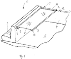
- a motor vehicle in the form of a passenger car has according to Fig. 1 a vehicle interior 1, which is provided with a rear-side cargo space.
- the rear-side cargo space has a load compartment floor 5, which is bounded to opposite longitudinal sides by a respective load compartment side wall 4. Seen in the normal direction of travel forward, the cargo space is limited by a backrest arrangement of a rear bench seat 2.
- the load compartment is assigned a protective device 3, which is described below with reference to Fig. 1 to 11 will be described in more detail.
- the protective device 3 has a dimensionally stable cassette housing 6, which is arranged fixed to the vehicle behind the backrest arrangement of the rear bench seat 2 and extends in the vehicle transverse direction across the width of the cargo space.
- a winding shaft 7 is rotatably mounted, on which a flexible sheet 8 in the form of a cover is held up and unwound.
- the flexible sheet 8 is pulled out through a longitudinal slot in the cassette housing 6 to a rear of the vehicle and pulled back through this longitudinal slot.
- the winding shaft 7 is permanently torqued by a return spring in the winding.
- the flexible sheet 8 has at its front end region in the extension direction a dimensionally stable guide profile 9, which extends over an entire width of the flexible sheet 8 and is guided parallelverlagerbar with its opposite Stirnend Schemeen 10 in load space fixed guide tracks 11 in the form of guide rails.
- the guide tracks 11 extend approximately at the level of the longitudinal slot of the cassette housing 6 along the respective loading space side wall 4 in the vehicle longitudinal direction to the rear, wherein each of the two guide tracks 11 is guided at least substantially parallel to the load compartment floor 5 in the opposite Laderaum cleansingwanditch 4.
- the two guide tracks 11 are integrated into the loading space side walls 4 and firmly connected to support structure parts of the vehicle body.
- the two guide tracks 11 extend over the length of the loading space.
- a driver 12 is guided in each case, which is movable over an unillustrated drive system along the respective guide track 11 in the vehicle longitudinal direction to the front and in the vehicle longitudinal direction to the rear.
- Both drivers 12 are by means of Drive system synchronously to each other in the opposite guide tracks 11 movable.
- the drive system has an electric motor and flexible drive transmission means in the form of thread pitch cables or in the form of flexible racks, which are driven synchronously and in opposite directions by means of a suitable transmission via the electric motor.
- the drive transmission means are connected to the respective driver 12, so that a displacement of the drive transmission means inevitably causes the desired displacement of the driver 12 in the guide tracks 11.
- the basic traversing function as well as the receiving and driving as well as release function of the driver in the vehicle longitudinal direction correspond in all embodiments according to the Fig. 1 to 11 in the EP 1 084 907 A2 described functions.
- the drivers 12 take the opposing front end regions 10 by means of a respective force-limited holding device.
- the force-limited effective holding device is arranged on the respective driver 12.
- the force-limited effective holding device has two leaf spring legs 13 which are firmly clamped on one side on the driver 12 and toward the cassette housing 6, ie the winding shaft 7, are open to allow a force-limited recording or releasing the respective front end portion 10 of the guide profile 9.
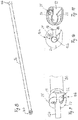
- a coupling member 14 to 16 is provided, which has a mushroom head 14 with a rectangular outer contour, a parallel to a central longitudinal axis of the guide profile 9 extended support pin 15 and an eccentric plate 16 from which the support pin 15 protrudes.
- the eccentric plate 16 is rotatably connected to the guide profile 9.
- the support pin 15 is fixedly arranged on the eccentric plate 16 and the mushroom head 14 is frontally attached to a projecting away from the eccentric plate 16, free end portion of the support pin 15.
- the mushroom head 14, the support pin 15 and the eccentric plate 16 are integrally formed with each other.
- the eccentric plate 16 is attached to the front side of the guide profile 9.
- the mushroom head 14, as shown by the Fig. 4 can be seen, an outer contour, which is provided with two wider edge legs and approximately at right angles thereto with two narrower edge legs.
- the two shorter edge legs form a broad attack surface when the mushroom head 14 according to Fig. 4 oriented upright.
- the two longer edge legs form a narrow attack surface of the mushroom head 14 when the mushroom head 14 is rotated by 90 °.
- the narrow attack surface is designed such that the mushroom head 14 in this narrower orientation, ie in the horizontal orientation of its wider attack surface, between the opposite leaf spring legs 13 of the force-limited effective holding device can slide freely without the leaf spring legs 13 cause a positive retention.
- the leaf spring legs 13 In the upright orientation, in which the broad attack surface of the mushroom head 14 according to Fig. 4 is effective, the leaf spring legs 13 form a force-limited, positive retention.
- the force limitation is effected by the elastic bending force of the leaf spring legs 13.
- the guide profile 9 is according to Fig. 4 aligned so that the eccentric plate 16 is extended forward relative to the rearwardly extended sheet 8 and the support pin 15 of each coupling member is spaced apart in parallel from the central longitudinal axis of the guide profile 9.
- the mushroom head 14 of the coupling member is aligned upright and locked between the leaf spring legs 13 of the force-limited effective holding device of the respective driver 12.
- Fig. 5 to 11 are in accordance with the protection device 3 in the same way Fig. 1 can be used as the previously described guide profile 9. functionally identical parts or sections are therefore provided with the same reference numerals with the addition of the letters a or b.
- the force-limited effective holding devices which are effective between the movable in the load-retaining guide tracks 11 drivers 12a, 12b and attached to the guide profile 9a coupling members of the opposite Stirnend Schemee 10a, 10b, the Stirnend Schemeen 10a, 10b of the respective guide profile 9a, 9b assigned are.
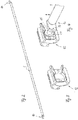
- Fig. 5 to 7 has the respective driver 12a, which is movable in the respective guide track 11, a projecting in the vehicle transverse direction inwardly Mit supportivezapfen, which is in positive contact with the corresponding force-limited holding device on the coupling member of the respective front end portion 10a.
- the force-limited effective holding device is formed by a force-limited rotatable holding leg 17 which is rotatably mounted limited to a rotational axis D at the fixed to the guide profile 9a Stirnend Scheme 10a.
- the holding leg 17 forms a pawl, which is positioned in the region of an upper side of the front end region 10a.
- the retaining leg 17 cooperates with a counter-support 18, which forms a guide surface for the driving pin of the driver 12a.
- the driving pin is held eccentrically offset from a central longitudinal axis of the guide profile 9a on the counter-support 18 and the holding leg 17.
- the retaining leg 17 may be additionally spring-loaded in the closing direction.
- the spring loading by a leg spring which is coaxial with the axis of rotation D between the front end portion 10a of the guide profile 9a and the holding leg 17 is effective.
- the axis of rotation D is parallel, but positioned eccentrically to the central longitudinal axis of the guide profile 9a.
- the driving pins of the drivers 12a take up the respective front end region 10a of the guide profile 9a Fig. 6 With.
- the holding leg 17 can according to Fig. 7 to escape upwards, whereby the driving pin of the driver 12 a between the counter-support 18 and the holding leg 17 can escape from the respective front end portion 10 a.
- the sheet 8 engages the guide profile 9a in the illustrations according to 6 and 7 on the right side of the plane of the drawing, so that the return force acting on the fabric 8 assists the release of the respective driver pin 12a of the drivers.
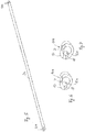
- the respective force-limited holding device is also associated with the respective coupling member of the respective front end region 10b of the guide profile 9b.
- the two drivers which are movable in the load-retaining guide tracks 11, are provided only with simple driving pins 12b, which protrude in the vehicle transverse direction towards the center of the cargo space inwards.
- Each coupling member on the opposite end faces 10b of the guide profile 9b has a support portion 19 fixedly connected to the guide profile 9b and a jaw portion 20 rotatably mounted on the support portion 19 about a rotation axis 21 and provided with the force-limited holding means.
- the force-limited effective holding device is formed by a leaf spring 22 which defines an open towards one side locking receptacle for the driving pin of the driver 12b (see Fig. 9 to 11 ). Also, the claw portion 22 is analogous to the opening of the leaf spring 22 open to one side.
- the axis of rotation 21 is positioned axially parallel to a central longitudinal axis of the guide profile 9b above the central longitudinal axis of the guide profile 9b on the holding section 19.
- the leaf spring 22 is according to Fig. 11 positioned in the rotatable jaw portion 20 and rotatable together with this.
- the sheet 8 exerts on the guide profile 9b due to the return force of the return spring of the winding shaft from a tensile load in a direction which is opposite to the opening of the leaf spring 22 and the claw portion 20 and thus in the drawing plane according to the 10 and 11 to the left.
- the claw portion 20 rotates together with the leaf spring 22, whereby the driving pin of the respective driver 12b can be released from the claw portion 20.
Landscapes
- Engineering & Computer Science (AREA)
- Mechanical Engineering (AREA)
- Vehicle Step Arrangements And Article Storage (AREA)
- Fittings On The Vehicle Exterior For Carrying Loads, And Devices For Holding Or Mounting Articles (AREA)
Description
- Die Erfindung betrifft eine Schutzvorrichtung für einen Fahrzeuginnenraum mit einem flexiblen Flächengebilde, das zwischen einer Ruhestellung und einer Schutzstellung verlagerbar ist, und das an einem Stirnendbereich mit einem formstabilen Führungsprofil versehen ist, das an seinen gegenüberliegenden Stirnseiten in fahrzeugfesten Führungsspuren geführt ist, wobei jeder Stirnseite des Führungsprofils ein Koppelglied zugeordnet ist, das mittels einer kraftbegrenzt wirksamen Halteeinrichtung mit einem in der jeweiligen Führungsspur geführten Mitnehmer in Wirkverbindung ist, wobei die Mitnehmer mittels eines Antriebssystems synchron zueinander in den Führungsspuren verfahrbar sind.
- Eine derartige Schutzvorrichtung ist aus der
EP 1 084 907 A2 bekannt. Die bekannte Schutzvorrichtung weist als Führungsspuren auf gegenüberliegenden Seitenwandungen eines Laderaumes Führungsschienen auf, in denen jeweils ein Mitnehmer geführt ist. Die Schutzvorrichtung ist mit einem flexiblen Schutzgebilde versehen, das auf einer Wickelwelle auf- und abwickelbar gelagert ist. An einem in Auszugrichtung vorderen Stirnendbereich weist das flexible Schutzgebilde ein formstabiles Auszugprofil auf, das in kraftbegrenzt wirksamen Halteeinrichtungen, die den Mitnehmern zugeordnet sind, gehalten ist, um längs der Führungsschienen und damit längs des Laderaumes verlagert zu werden. - Aufgabe der Erfindung ist es, eine Schutzvorrichtung der eingangs genannten Art zu schaffen, die in verbesserter Weise Beschädigungen bei unsachgemäßer Handhabung vermeidet.
- Diese Aufgabe wird dadurch gelöst, dass die Koppelglieder exzentrisch versetzt zu einer Mittellängsachse des Führungsprofils mit den Mitnehmern in Wirkverbindung sind, und dass die Koppelglieder von den Mitnehmern lösbar sind abhängig von externen Belastungen des Führungsprofils in Richtungskomponenten, die orthogonal zu einer Aufspannebene des Flächengebildes erstreckt sind. Beim Stand der Technik führen orthogonale Belastungen zu Beschädigungen des Führungsprofils und der Schutzvorrichtung. Dies wird bei der erfindungsgemäßen Lösung vermieden, da bei Belastungen auf das Führungsprofil in Richtungskomponenten, die orthogonal zu der Aufspannebene des Flächengebildes erstreckt sind, aufgrund der exzentrischen Versetzung der Koppelglieder Drehmomente zu einem Verdrehen der kraftbegrenzt wirksamen Halteeinrichtungen bzw. der Koppelglieder führen, die ein Lösen der Koppelglieder von den Mitnehmern auch bei Belastungen in den genannten unterschiedlichen Richtungskomponenten bewirken. Die erfindungsgemäße Lösung eignet sich in besonders vorteilhafter Weise für eine im Wesentlichen horizontale Laderaumabdeckung bei einem Personenkraftwagen, bei der unbeabsichtigte Bewegungen einer Bedienperson beim Be- oder Entladen von Transportgut entsprechende Belastungen auf das Führungsprofil ausüben können. Erfindungsgemäß erfolgt statt einer Beschädigung des Führungsprofils lediglich ein Lösen des Führungsprofils von den Mitnehmern, die in den fahrzeugfesten Führungsspuren geführt sind. Als fahrzeugfeste Führungsspuren sind insbesondere Führungsschienen vorgesehen, die in gegenüberliegenden Laderaumseitenwandungen integriert sind, und die knapp unterhalb einer Innenraumbrüstung und damit knapp unterhalb einer Fahrzeuggürtellinie verlaufen. Die erfindungsgemäße Lösung ist auch für andere Arten von Schutzvorrichtungen, insbesondere für Sonnenschutzvorrichtungen, in einem Fahrzeuginnenraum vorgesehen.
- In Ausgestaltung der Erfindung ist die kraftbegrenzt wirksame Halteeinrichtung dem Mitnehmer oder dem Koppelglied zugeordnet. Das Führungsprofil weist auf jeder seiner gegenüberliegenden Stirnseiten jeweils ein Koppelglied auf. In gleicher Weise sind auch auf gegenüberliegenden Seiten des Fahrzeuginnenraumes entsprechende Führungsspuren vorgesehen, in denen jeweils ein Mitnehmer zur Mitnahme, Freigabe oder Aufnahme des jeweiligen Koppelgliedes des Führungsprofils vorgesehen ist. Entsprechend sind auch auf jeder der beiden Stirnseiten des Führungsprofils jeweils eine kraftbegrenzt wirksame Halteeinrichtung vorgesehen, die entweder am jeweiligen Koppelglied oder am jeweiligen Mitnehmer vorgesehen sind. Die kraftbegrenzte Wirksamkeit der Halteeinrichtung ist vorzugsweise mechanisch ausgeführt.
- In weiterer Ausgestaltung der Erfindung sind die Koppelglieder an dem Führungsprofil fest angeordnet. Die Koppelglieder können an der jeweiligen Stirnseite des Führungsprofils einstückig angeformt oder an der jeweiligen Stirnseite lösbar oder unlösbar befestigt sein.
- In weiterer Ausgestaltung der Erfindung weist jedes Koppelglied eine Außenkontur mit einer schmalen und einer in Umfangsrichtung versetzten breiten Angriffsfläche auf, wobei die Angriffsflächen je nach Drehstellung des Koppelgliedes alternativ der kraftbegrenzt wirksamen Halteeinrichtung zugeordnet sind. Dadurch kann die kraftbegrenzt wirksame Halteeinrichtung abhängig von der Drehstellung des Koppelgliedes das Koppelglied halten oder freigeben.
- In weiterer Ausgestaltung der Erfindung ist die kraftbegrenzt wirksame Halteeinrichtung um eine Drehachse drehbar an dem Koppelglied oder an dem Mitnehmer angeordnet, die parallel zu der Mittellängsachse des Führungsprofils ausgerichtet ist. Durch die parallele, aber exzentrische Ausrichtung der Drehachse relativ zu der Mittellängsachse des Führungsprofils führen entsprechende Belastungen auf das Führungsprofil mit Richtungskomponenten orthogonal zur Aufspannebene des flexiblen Flächengebildes zwangsläufig zu einem Drehmoment auf die Halteeinrichtung, wodurch eine Freigabe der Halteeinrichtung in die entsprechende Richtungskomponente erzielbar ist. Unter dem Begriff der Richtungskomponente ist nicht eine resultierende Richtung, sondern vielmehr wenigstens eine Richtungskomponente zu verstehen, aus denen sich die resultierende Richtung einer entsprechenden Belastung auf das Führungsprofil zusammensetzt.
- In weiterer Ausgestaltung der Erfindung weist die kraftbegrenzt wirksame Halteeinrichtung wenigstens einen kraftbegrenzt beweglichen Halteschenkel auf, der eine Außenkontur des Koppelgliedes oder des Mitnehmers flankiert. In besonders vorteilhafter Weise ist als Halteeinrichtung wenigstens eine einseitig eingespannte Blattfeder vorgesehen, die derart gebogen sein kann, dass sie einen Teil einer Außenkontur des Koppelgliedes oder des Mitnehmers formschlüssig umschließt. Die elastische Nachgiebigkeit der Blattfeder führt zu der kraftbegrenzten Wirkverbindung und demzufolge zur kraftbegrenzten Freigabe der Haltereinrichtung.
- Weitere Vorteile und Merkmale der Erfindung ergeben sich aus den Ansprüchen sowie aus der nachfolgenden Beschreibung bevorzugter Ausführungsbeispiele der Erfindung, die anhand der Zeichnungen dargestellt sind.
- Fig. 1
- zeigt schematisch eine Ausführungsform einer erfindungsgemäßen Schutzvorrichtung für einen Laderaum innerhalb eines Fahrzeuginnenraums eines Personenkraftwagens,
- Fig. 2
- in vergrößerter perspektivischer Darstellung einen Teilbereich einer Schutzvorrichtung gemäß
Fig. 1 im Bereich eines Führungsprofils eines flexiblen Flächengebildes, - Fig. 3
- eine Funktionseinheit der Schutzvorrichtung gemäß den
Fig. 1 und2 zur Aufnahme einer Stirnseite des Führungsprofils gemäßFig. 2 , - Fig. 4
- die Darstellung nach
Fig. 3 , jedoch mit aufgenommener Stirnseite des Führungsprofils, - Fig. 5
- ein Führungsprofil mit seitlich angeordneten Koppelgliedern gemäß einer weiteren Ausführungsform einer erfindungsgemäßen Schutzvorrichtung,
- Fig. 6
- in einer Seitenansicht das Führungsprofil nach
Fig. 5 mit aufgenommenem, laderaumseitigem Mitnehmer, - Fig. 7
- die Darstellung nach
Fig. 6 in einer Lösestellung, - Fig. 8
- in perspektivischer Darstellung ein Führungsprofil für eine weitere Ausführungsform einer erfindungsgemäßen Schutzvorrichtung gemäß
Fig. 1 , - Fig. 9
- in vergrößerter Darstellung einen Ausschnitt des Führungsprofils im Bereich einer Kopplung mit einem laderaumseitigen Mitnehmer,
- Fig. 10
- eine Seitenansicht der Darstellung gemäß
Fig. 9 und - Fig. 11
- einen Querschnitt durch die Funktionseinheit gemäß den
Fig. 9 und 10 . - Ein Kraftfahrzeug in Form eines Personenkraftwagens weist gemäß
Fig. 1 einen Fahrzeuginnenraum 1 auf, der mit einem heckseitigen Laderaum versehen ist. Der heckseitige Laderaum weist einen Laderaumboden 5 auf, der zu gegenüberliegenden Längsseiten hin durch jeweils eine Laderaumseitenwandung 4 begrenzt ist. In normaler Fahrtrichtung gesehen nach vorne ist der Laderaum durch eine Rückenlehnenanordnung einer Fondsitzbank 2 begrenzt. Dem Laderaum ist eine Schutzvorrichtung 3 zugeordnet, die nachfolgend anhand derFig. 1 bis 11 näher beschrieben wird. - Die Schutzvorrichtung 3 weist ein formstabiles Kassettengehäuse 6 auf, das hinter der Rückenlehnenanordnung der Fondsitzbank 2 fahrzeugfest angeordnet ist und sich in Fahrzeugquerrichtung über die Breite des Laderaumes erstreckt. In dem Kassettengehäuse 6 ist eine Wickelwelle 7 drehbar gelagert, auf der ein flexibles Flächengebilde 8 in Form einer Abdeckbahn auf- und abwickelbar gehalten ist. Das flexible Flächengebilde 8 wird durch einen Längsschlitz in dem Kassettengehäuse 6 zu einem Fahrzeugheck hin nach hinten ausgezogen und durch diesen Längsschlitz auch wieder eingezogen. Die Wickelwelle 7 ist durch eine Rückholfeder in Aufwickelrichtung permanent drehmomentbeaufschlagt. Das flexible Flächengebilde 8 weist an seinem in Auszugrichtung vorderen Stirnendbereich ein formstabiles Führungsprofil 9 auf, das sich über eine gesamte Breite des flexiblen Flächengebildes 8 erstreckt und mit seinen gegenüberliegenden Stirnendbereichen 10 in laderaumfesten Führungsspuren 11 in Form von Führungsschienen parallelverlagerbar geführt ist. Die Führungsspuren 11 erstrecken sich etwa auf Höhe des Längsschlitzes des Kassettengehäuses 6 entlang der jeweiligen Laderaumseitenwandung 4 in Fahrzeuglängsrichtung nach hinten, wobei jede der beiden Führungsspuren 11 in den gegenüberliegenden Laderaumseitenwandungen 4 zumindest weitgehend parallel zu dem Laderaumboden 5 geführt ist. Die beiden Führungsspuren 11 sind in den Laderaumseitenwandungen 4 integriert und fest mit Tragstrukturteilen der Fahrzeugkarosserie verbunden. Die beiden Führungsspuren 11 erstrecken sich über die Länge des Laderaumes.
- In jeder Führungsspur 11 ist jeweils ein Mitnehmer 12 geführt, der über ein nicht dargestelltes Antriebssystem entlang der jeweiligen Führungsspur 11 in Fahrzeuglängsrichtung nach vorne sowie in Fahrzeuglängsrichtung nach hinten verfahrbar ist. Beide Mitnehmer 12 sind mittels des Antriebssystems synchron zueinander in den gegenüberliegenden Führungsspuren 11 verfahrbar. Das Antriebssystem weist einen Elektromotor sowie flexible Antriebsübertragungsmittel in Form von Gewindesteigungskabeln oder in Form flexibler Zahnstangen auf, die mittels eines geeigneten Getriebes über den Elektromotor synchron und gegenläufig zueinander angetrieben werden. Die Antriebsübertragungsmittel sind mit dem jeweiligen Mitnehmer 12 verbunden, so dass eine Verlagerung der Antriebsübertragungsmittel zwangsläufig die gewünschte Verlagerung der Mitnehmer 12 in den Führungsspuren 11 bewirkt. Die grundsätzliche Verfahrfunktion sowie die Aufnahme- und Mitnahme- wie auch Freigabefunktion der Mitnehmer in Fahrzeuglängsrichtung entsprechen bei allen Ausführungsformen gemäß den
Fig. 1 bis 11 den in derEP 1 084 907 A2 beschriebenen Funktionen. - Die Mitnehmer 12 nehmen die gegenüberliegenden Stirnendbereiche 10 mittels jeweils einer kraftbegrenzt wirksamen Halteeinrichtung mit. Bei der Ausführungsform gemäß den
Fig. 2 bis 4 ist die kraftbegrenzt wirksame Halteeinrichtung an dem jeweiligen Mitnehmer 12 angeordnet. Die kraftbegrenzt wirksame Halteeinrichtung weist zwei Blattfederschenkel 13 auf, die einseitig am Mitnehmer 12 fest eingespannt sind und in Richtung zum Kassettengehäuse 6 hin, d. h. zur Wickelwelle 7, offen sind, um ein kraftbegrenztes Aufnehmen oder Freigeben des jeweiligen Stirnendbereichs 10 des Führungsprofils 9 zu ermöglichen. An jedem Stirnendbereich 10 des Führungsprofils 9 ist ein Koppelglied 14 bis 16 vorgesehen, das einen Pilzkopf 14 mit einer rechteckartigen Außenkontur, einen parallel zu einer Mittellängsachse des Führungsprofils 9 erstreckten Trägerzapfen 15 sowie eine Exzenterplatte 16 aufweist, von der der Trägerzapfen 15 abragt. Die Exzenterplatte 16 ist drehfest mit dem Führungsprofil 9 verbunden. Der Trägerzapfen 15 ist fest an der Exzenterplatte 16 angeordnet und der Pilzkopf 14 ist stirnseitig an einem von der Exzenterplatte 16 wegragenden, freien Endbereich des Trägerzapfens 15 befestigt. Beim dargestellten Ausführungsbeispiel sind der Pilzkopf 14, der Trägerzapfen 15 und die Exzenterplatte 16 einstückig zueinander gestaltet. Die Exzenterplatte 16 ist stirnseitig an dem Führungsprofil 9 befestigt. - Der Pilzkopf 14 weist, wie anhand der
Fig. 4 erkennbar ist, eine Außenkontur auf, die mit zwei breiteren Randschenkeln sowie etwa rechtwinklig hierzu mit zwei schmaleren Randschenkeln versehen ist. Die beiden kürzeren Randschenkel bilden eine breite Angriffsfläche, wenn der Pilzkopf 14 gemäßFig. 4 hochkant ausgerichtet ist. Die beiden längeren Randschenkel bilden eine schmale Angriffsfläche des Pilzkopfes 14, wenn der Pilzkopf 14 um 90° verdreht ist. Die schmale Angriffsfläche ist derart gestaltet, dass der Pilzkopf 14 in dieser schmaleren Ausrichtung, d. h. in der horizontalen Ausrichtung seiner breiteren Angriffsfläche, zwischen den gegenüberliegenden Blattfederschenkeln 13 der kraftbegrenzt wirksamen Halteeinrichtung frei herausgleiten kann, ohne dass die Blattfederschenkel 13 einen formschlüssigen Rückhalt bewirken. In der Hochkantausrichtung, in der die breite Angriffsfläche des Pilzkopfes 14 gemäßFig. 4 wirksam ist, bilden die Blattfederschenkel 13 einen kraftbegrenzten, formschlüssigen Rückhalt. Die Kraftbegrenzung erfolgt durch die elastische Biegekraft der Blattfederschenkel 13. - Im normalen Betrieb der Schutzvorrichtung 3 ist das Führungsprofil 9 gemäß
Fig. 4 ausgerichtet, so dass die Exzenterplatte 16 relativ zu dem nach hinten erstreckten Flächengebilde 8 nach vorne erstreckt ist und der Trägerzapfen 15 jedes Koppelgliedes in Abstand parallel vor der Mittellängsachse des Führungsprofils 9 positioniert ist. In dieser Ausrichtung ist der Pilzkopf 14 des Koppelgliedes hochkant ausgerichtet und zwischen den Blattfederschenkeln 13 der kraftbegrenzt wirksamen Halteeinrichtung des jeweiligen Mitnehmers 12 eingerastet. Sobald nun durch eine Bedienperson beabsichtigt oder unbeabsichtigt auf das Führungsprofil 9 eine Belastung mit einer Richtungskomponente nach oben oder nach unten erfolgt (siehe Pfeildarstellung inFig. 4 ), wird aufgrund der exzentrischen Anordnung des Trägerzapfens 15 zwangsläufig ein Drehmoment auf die Exzenterplatte 16, auf den Trägerzapfen 15 und auf den Pilzkopf 14 und damit auf das Koppelglied insgesamt ausgeübt (siehe Pfeildarstellung inFig. 4 ), wodurch der Pilzkopf 14 sich innerhalb der kraftbegrenzt wirksamen Halteeinrichtung des jeweiligen Mitnehmers 12 um 90° verdreht. Dadurch kommt der Pilzkopf 14 und damit das jeweilige Koppelglied vom Mitnehmer 12 frei, wodurch das permanent in Aufwickelrichtung durch die Rückholfeder der Wickelwelle beaufschlagte Flächengebilde 8 das Führungsprofil 9 zum Kassettengehäuse 6 nach hinten, d. h. in Fahrzeuglängsrichtung nach vorne, zieht. Die durch das Flächengebilde 8 wirkende Zugkraft auf das Führungsprofil 9 dreht das Führungsprofil 9 und demzufolge auch die Koppelglieder 14 bis 16 an den gegenüberliegenden Stirnendbereichen 10 des Führungsprofiles 9 zwangsläufig wieder in die Ausrichtung gemäßFig. 4 , in der der jeweilige Pilzkopf 14 hochkant aufgestellt ist und der Trägerzapfen 15 vor dem Führungsprofil 9 positioniert ist. - Die Ausführungsformen gemäß den
Fig. 5 bis 11 sind in gleicher Weise bei der Schutzvorrichtung 3 gemäßFig. 1 einsetzbar wie das zuvor beschriebene Führungsprofil 9. Funktionsgleiche Teile oder Abschnitte sind demzufolge mit gleichen Bezugszeichen unter Hinzufügung der Buchstaben a oder b versehen. Wesentlicher Unterschied bei den beiden Ausführungsformen gemäß denFig. 5 bis 11 ist es, dass die kraftbegrenzt wirksamen Halteeinrichtungen, die zwischen den in den laderaumfesten Führungsspuren 11 verfahrbaren Mitnehmern 12a, 12b und den am Führungsprofil 9a befestigten Koppelgliedern der gegenüberliegenden Stirnendbereiche 10a, 10b wirksam sind, den Stirnendbereichen 10a, 10b des jeweiligen Führungsprofils 9a, 9b zugeordnet sind. - Bei der Ausführungsform nach den
Fig. 5 bis 7 weist der jeweilige Mitnehmer 12a, der in der jeweiligen Führungsspur 11 verfahrbar ist, einen in Fahrzeugquerrichtung nach innen abragenden Mitnehmerzapfen auf, der mit der entsprechenden kraftbegrenzt wirksamen Halteeinrichtung am Koppelglied des jeweiligen Stirnendbereichs 10a in formschlüssigem Kontakt ist. Die kraftbegrenzt wirksame Halteeinrichtung wird durch einen kraftbegrenzt drehbeweglichen Halteschenkel 17 gebildet, der um eine Drehachse D an dem mit dem Führungsprofil 9a festen Stirnendbereich 10a begrenzt drehbar gelagert ist. Der Halteschenkel 17 bildet eine Sperrklinke, die im Bereich einer Oberseite des Stirnendbereichs 10a positioniert ist. Der Halteschenkel 17 wirkt mit einer Gegenstütze 18 zusammen, die eine Führungsfläche für den Mitnehmerzapfen des Mitnehmers 12a bildet. Anhand derFig. 6 und 7 ist erkennbar, dass der Mitnehmerzapfen exzentrisch versetzt zu einer Mittellängsachse des Führungsprofils 9a an der Gegenstütze 18 und dem Halteschenkel 17 gehalten ist. Der Halteschenkel 17 kann in Schließrichtung ergänzend federbelastet sein. Vorzugsweise erfolgt die Federbelastung durch eine Schenkelfeder, die koaxial zur Drehachse D zwischen dem Stirnendbereich 10a des Führungsprofils 9a und dem Halteschenkel 17 wirksam ist. Die Drehachse D ist parallel, jedoch exzentrisch zur Mittellängsachse des Führungsprofils 9a positioniert. - Im normalen Betrieb nehmen die Mitnehmerzapfen der Mitnehmer 12a den jeweiligen Stirnendbereich 10a des Führungsprofils 9a gemäß
Fig. 6 mit. Sobald auf das Führungsprofil 9a eine Belastung von oben ausgeübt wird, kann der Halteschenkel 17 gemäßFig. 7 nach oben ausweichen, wodurch der Mitnehmerbolzen des Mitnehmers 12a zwischen der Gegenstütze 18 und dem Halteschenkel 17 hindurch von dem jeweiligen Stirnendbereich 10a freikommen kann. Das Flächengebilde 8 greift an dem Führungsprofil 9a in den Darstellungen gemäßFig. 6 und 7 auf der rechten Seite der Zeichnungsebene an, so dass die auf das Flächengebilde 8 wirkende Rückholkraft das Freikommen des jeweiligen Mitnehmerzapfens der Mitnehmer 12a unterstützt. - Bei der Ausführungsform nach den
Fig. 8 bis 11 ist die jeweilige kraftbegrenzt wirksame Halteeinrichtung ebenfalls dem jeweiligen Koppelglied des jeweiligen Stirnendbereichs 10b des Führungsprofils 9b zugeordnet. Die beiden Mitnehmer, die in den laderaumfesten Führungsspuren 11 verfahrbar sind, sind lediglich mit einfachen Mitnehmerzapfen 12b versehen, die in Fahrzeugquerrichtung zur Mitte des Laderaumes hin nach innen abragen. Jedes Koppelglied an den gegenüberliegenden Stirnendbereichen 10b des Führungsprofils 9b weist einen mit dem Führungsprofil 9b fest verbundenen Trägerabschnitt 19 sowie einen an dem Trägerabschnitt 19 um eine Drehachse 21 drehbeweglich gelagerten Klauenabschnitt 20 auf, der mit der kraftbegrenzt wirksamen Halteeinrichtung versehen ist. Die kraftbegrenzt wirksame Halteeinrichtung wird durch eine Blattfeder 22 gebildet, die eine zu einer Seite hin offene Rastaufnahme für den Mitnehmerzapfen des Mitnehmers 12b definiert (sieheFig. 9 bis 11 ). Auch der Klauenabschnitt 22 ist analog zur Öffnung der Blattfeder 22 zu einer Seite hin offen. - Die Drehachse 21 ist achsparallel versetzt zu einer Mittellängsachse des Führungsprofils 9b oberhalb der Mittellängsachse des Führungsprofils 9b an dem Halteabschnitt 19 positioniert. Die Blattfeder 22 ist gemäß
Fig. 11 in dem drehbeweglichen Klauenabschnitt 20 positioniert und gemeinsam mit diesem verdrehbar. Das Flächengebilde 8 übt auf das Führungsprofil 9b aufgrund der Rückholkraft der Rückholfeder der Wickelwelle eine Zugbelastung in einer Richtung aus, die entgegengerichtet ist zu der Öffnung der Blattfeder 22 und des Klauenabschnittes 20 und damit in der Zeichnungsebene gemäß denFig. 10 und 11 nach links. - Sobald auf das Führungsprofil 9b eine beabsichtigte oder unbeabsichtigte Belastung mit einer Richtungskomponente in Fahrzeughochrichtung nach oben oder nach unten erfolgt, verdreht sich der Klauenabschnitt 20 gemeinsam mit der Blattfeder 22 entsprechend, wodurch der Mitnehmerzapfen des jeweiligen Mitnehmers 12b aus dem Klauenabschnitt 20 freikommen kann.
Claims (7)
- Schutzvorrichtung für einen Fahrzeuginnenraum mit einem flexiblen Flächengebilde (8), das zwischen einer Ruhestellung und einer Schutzstellung verlagerbar ist, und das an einem Stirnendbereich mit einem formstabilen Führungsprofil (9, 9a, 9b) versehen ist, das an seinen gegenüberliegenden Stirnseiten in fahrzeugfesten Führungsspuren (11) geführt ist, wobei jeder Stirnseite des Führungsprofils (9, 9a, 9b) ein Koppelglied zugeordnet ist, das mittels einer kraftbegrenzt wirksamen Halteeinrichtung mit einem in der jeweiligen Führungsspur (11) geführten Mitnehmer (12, 12a, 12b) in Wirkverbindung ist, wobei die Mitnehmer (12, 12a, 12b) mittels eines Antriebssystems synchron zueinander in den Führungsspuren (11) verfahrbar sind, dadurch gekennzeichnet, dass die Koppelglieder exzentrisch versetzt zu einer Mittellängsachse des Führungsprofils (9, 9a, 9b) mit den Mitnehmern (12, 12a, 12b) in Wirkverbindung sind, und dass die Koppelglieder von den Mitnehmern (12, 12a, 12b) lösbar sind abhängig von externen Belastungen des Führungsprofils (9, 9a, 9b) in Richtungskomponenten, die orthogonal zu einer Aufspannebene des Flächengebildes (8) erstreckt sind.
- Schutzvorrichtung nach Anspruch 1, dadurch gekennzeichnet, dass die kraftbegrenzt wirksame Halteeinrichtung dem Mitnehmer (12) oder dem Koppelglied zugeordnet ist.
- Schutzvorrichtung nach Anspruch 1 oder 2, dadurch gekennzeichnet, dass die Koppelglieder an dem Führungsprofil (9) fest angeordnet sind.
- Schutzvorrichtung nach Anspruch 3, dadurch gekennzeichnet, dass jedes Koppelglied eine Außenkontur mit einer schmalen und einer in Umfangsrichtung versetzten breiten Angriffsfläche aufweist, wobei die Angriffsflächen je nach Drehstellung des Koppelgliedes alternativ der kraftbegrenzt wirksamen Halteeinrichtung zugeordnet sind.
- Schutzvorrichtung nach Anspruch 1 oder 2, dadurch gekennzeichnet, dass die kraftbegrenzt wirksame Halteeinrichtung um eine Drehachse (D, 21) drehbar an dem Koppelglied oder an dem Mitnehmer angeordnet ist, die parallel zu der Mittellängsachse des Führungsprofils (9a, 9b) ausgerichtet ist.
- Schutzvorrichtung nach Anspruch 5, dadurch gekennzeichnet, dass die kraftbegrenzt wirksame Halteeinrichtung wenigstens einen kraftbegrenzt beweglichen Halteschenkel (17) aufweist, der eine Außenkontur des Koppelgliedes oder des Mitnehmers (12a) flankiert.
- Schutzvorrichtung nach Anspruch 5, dadurch gekennzeichnet, dass die kraftbegrenzt wirksame Halteeinrichtung wenigstens eine einseitig eingespannte Blattfeder (22) aufweist.
Applications Claiming Priority (1)
| Application Number | Priority Date | Filing Date | Title |
|---|---|---|---|
| DE102016215599.7A DE102016215599B3 (de) | 2016-08-19 | 2016-08-19 | Schutzvorrichtung für einen Fahrzeuginnenraum |
Publications (2)
| Publication Number | Publication Date |
|---|---|
| EP3284635A1 true EP3284635A1 (de) | 2018-02-21 |
| EP3284635B1 EP3284635B1 (de) | 2019-03-06 |
Family
ID=59295692
Family Applications (1)
| Application Number | Title | Priority Date | Filing Date |
|---|---|---|---|
| EP17180976.7A Active EP3284635B1 (de) | 2016-08-19 | 2017-07-12 | Schutzvorrichtung für einen fahrzeuginnenraum |
Country Status (4)
| Country | Link |
|---|---|
| US (1) | US10457219B2 (de) |
| EP (1) | EP3284635B1 (de) |
| CN (1) | CN107757501B (de) |
| DE (1) | DE102016215599B3 (de) |
Families Citing this family (5)
| Publication number | Priority date | Publication date | Assignee | Title |
|---|---|---|---|---|
| JP6793545B2 (ja) * | 2016-12-28 | 2020-12-02 | 矢崎総業株式会社 | 巻取装置及び配索構造 |
| KR102542953B1 (ko) | 2018-04-12 | 2023-06-13 | 현대자동차주식회사 | 차량의 러기지룸 스크린 장치 |
| FR3088270B1 (fr) * | 2018-11-08 | 2020-12-11 | Treves Products Services & Innovation | Systeme de recouvrement d’un compartiment a bagages de vehicule automobile |
| FR3096631B1 (fr) * | 2019-05-31 | 2021-11-12 | Inteva Products France Sas | Cache-bagages motorisé pour vehicule |
| KR102906465B1 (ko) * | 2023-11-03 | 2025-12-31 | 주식회사 서연이화 | 카고 스크린의 하우징 커버 |
Citations (5)
| Publication number | Priority date | Publication date | Assignee | Title |
|---|---|---|---|---|
| EP1084907A2 (de) * | 1999-09-20 | 2001-03-21 | BOS GmbH & Co. KG | Schutzvorrichtung für einen Innenraum eines Kraftfahrzeuges |
| JP2003127777A (ja) * | 2001-10-23 | 2003-05-08 | Kasai Kogyo Co Ltd | 車両用トノカバー装置 |
| JP2007153128A (ja) * | 2005-12-05 | 2007-06-21 | Mazda Motor Corp | 車体後部構造 |
| DE102009036606B3 (de) * | 2009-07-30 | 2010-08-12 | Bos Gmbh & Co. Kg | Schutzvorrichtung für einen Fahrzeuginnenraum |
| DE102009023723A1 (de) * | 2009-06-03 | 2010-12-09 | Bayerische Motoren Werke Aktiengesellschaft | Kraftfahrzeug |
Family Cites Families (22)
| Publication number | Priority date | Publication date | Assignee | Title |
|---|---|---|---|---|
| US5860466A (en) * | 1996-02-02 | 1999-01-19 | Kao; Nien Tsu Tim | Windshield shelter |
| US6003920A (en) * | 1997-06-17 | 1999-12-21 | Peter Butz Gmbh & Co. | Cargo-space cover for motor vehicle |
| DE10102627A1 (de) * | 2001-01-18 | 2002-08-01 | Bos Gmbh | Abdeckvorrichtung für einen Laderaum eines Kraftfahrzeugs |
| DE10356911B3 (de) * | 2003-12-02 | 2005-01-20 | Bos Gmbh & Co. Kg | Laderaumschutzvorrichtung für ein Kraftfahrzeug |
| DE102004008874A1 (de) * | 2004-02-18 | 2005-09-08 | Bos Gmbh & Co. Kg | Funktionseinheit für einen Fahrzeuginnenraum |
| DE102004029042A1 (de) * | 2004-06-08 | 2005-12-29 | Bos Gmbh & Co. Kg | Schutzvorrichtung für einen Fahrzeuginnenraum |
| DE102005033819A1 (de) * | 2005-07-11 | 2007-01-25 | Bos Gmbh & Co. Kg | Laderaumschutzvorrichtung mit wenigstens einer Wickelwelle |
| DE102005048207B3 (de) * | 2005-10-07 | 2006-11-23 | Webasto Ag | Rolloanordnung für ein Kraftfahrzeug |
| DE102005055625C5 (de) * | 2005-11-22 | 2010-05-20 | Bayerische Motoren Werke Aktiengesellschaft | Laderaumabdeckung für ein Fahrzeug |
| EP1787864B1 (de) | 2005-11-22 | 2009-03-25 | Mazda Motor Corporation | Hintere Struktur eines Kraftfahrzeugs |
| JP4247751B2 (ja) * | 2006-08-10 | 2009-04-02 | トヨタ紡織株式会社 | サンシェード装置 |
| US7673921B2 (en) * | 2007-01-24 | 2010-03-09 | Mazda Motor Corporation | Tonneau cover device of vehicle |
| DE202007016329U1 (de) * | 2007-09-14 | 2008-02-14 | Bos Gmbh & Co. Kg | Schutzvorrichtung für einen Fahrzeuginnenraum |
| DE102007057074A1 (de) * | 2007-11-23 | 2009-06-04 | Bos Gmbh & Co. Kg | Rollosystem |
| KR101220052B1 (ko) * | 2010-10-13 | 2013-01-21 | 현대자동차주식회사 | 러기지 룸 스크린의 오토 리턴 구조 |
| TWM428992U (en) * | 2011-12-08 | 2012-05-11 | Macauto Ind Co Ltd | Track type sunshade device |
| US20130153160A1 (en) * | 2011-11-18 | 2013-06-20 | Macauto Industrial Co., Ltd. | Sunshade assembly |
| DE102012221586B8 (de) * | 2012-11-26 | 2014-08-14 | Bos Gmbh & Co. Kg | Schutzvorrichtung für einen Raumabschnitt eines Kraftfahrzeugs |
| DE102012221585B4 (de) * | 2012-11-26 | 2016-11-24 | Bos Gmbh & Co. Kg | Rückhaltevorrichtung für einen Fahrzeuginnenraum |
| DE102013210191B4 (de) * | 2013-05-31 | 2017-10-19 | Bos Gmbh & Co. Kg | Schutzvorrichtung für einen Fahrzeuginnenraum |
| DE102013022154A1 (de) * | 2013-12-30 | 2015-07-02 | Volkswagen Aktiengesellschaft | Abdeckvorrichtung |
| DE102015118775B4 (de) * | 2015-11-03 | 2019-02-21 | Macauto Industrial Co., Ltd. | Laderaumabdeckung |
-
2016
- 2016-08-19 DE DE102016215599.7A patent/DE102016215599B3/de not_active Expired - Fee Related
-
2017
- 2017-07-12 EP EP17180976.7A patent/EP3284635B1/de active Active
- 2017-07-31 US US15/664,684 patent/US10457219B2/en active Active
- 2017-08-18 CN CN201710711500.XA patent/CN107757501B/zh active Active
Patent Citations (5)
| Publication number | Priority date | Publication date | Assignee | Title |
|---|---|---|---|---|
| EP1084907A2 (de) * | 1999-09-20 | 2001-03-21 | BOS GmbH & Co. KG | Schutzvorrichtung für einen Innenraum eines Kraftfahrzeuges |
| JP2003127777A (ja) * | 2001-10-23 | 2003-05-08 | Kasai Kogyo Co Ltd | 車両用トノカバー装置 |
| JP2007153128A (ja) * | 2005-12-05 | 2007-06-21 | Mazda Motor Corp | 車体後部構造 |
| DE102009023723A1 (de) * | 2009-06-03 | 2010-12-09 | Bayerische Motoren Werke Aktiengesellschaft | Kraftfahrzeug |
| DE102009036606B3 (de) * | 2009-07-30 | 2010-08-12 | Bos Gmbh & Co. Kg | Schutzvorrichtung für einen Fahrzeuginnenraum |
Also Published As
| Publication number | Publication date |
|---|---|
| CN107757501A (zh) | 2018-03-06 |
| US20180050643A1 (en) | 2018-02-22 |
| DE102016215599B3 (de) | 2017-07-27 |
| CN107757501B (zh) | 2022-04-01 |
| US10457219B2 (en) | 2019-10-29 |
| EP3284635B1 (de) | 2019-03-06 |
Similar Documents
| Publication | Publication Date | Title |
|---|---|---|
| EP3284635B1 (de) | Schutzvorrichtung für einen fahrzeuginnenraum | |
| DE102009024292B4 (de) | Gurtaufroller für einen Sicherheitsgurt eines Kraftfahrzeuges | |
| EP2042376A1 (de) | Schutzvorrichtung für einen Fahrzeuginnenraum | |
| WO2016037869A1 (de) | Vorrichtung zur ladungssicherung | |
| WO2006010484A1 (de) | Zum fahrzeuginsassen abknickender gurtbringer | |
| DE102012004999A1 (de) | Kraftfahrzeuganhängevorrichtung | |
| EP1741600A1 (de) | Laderaumschutzvorrichtung für ein Kraftfahrzeug | |
| DE102013210191B4 (de) | Schutzvorrichtung für einen Fahrzeuginnenraum | |
| WO2017144280A1 (de) | Befestigungsvorrichtung für einen lastenträger | |
| DE102011079924B4 (de) | Schutzvorrichtung für einen Fahrzeuginnenraum | |
| EP1122121B1 (de) | Transportbehälter-Einrichtung für den Einbau in Kraftfahrzeuge, wie z.B. Durchladeeinrichtung | |
| EP0492035A1 (de) | Anhängevorrichtung für insbesondere Personenkraftwagen | |
| DE102009036605B3 (de) | Haltevorrichtung für ein Kassettengehäuse | |
| EP2922728A1 (de) | Schutzvorrichtung für einen fahrzeuginnenraum sowie hubmechanik hierfür | |
| DE102019112908B4 (de) | Fahrzeugkomponente mit wenigstens einer Befestigungsanordnung für wenigstens ein Scanmodul | |
| DE102018201268B4 (de) | Schutzvorrichtung für einen Kraftfahrzeuginnenraum | |
| DE19836849C1 (de) | Dachanordnung | |
| DE10046142B4 (de) | Vorrichtung zur Festlegung eines Endbereiches einer Fahrzeug- Sicherheitseinrichtung an einem fahrzeugseitigen Befestigungspunkt sowie zur Spannung des Endbereichs der Fahrzeug-Sicherheitseinrichtung relativ zu dem Befestigungspunkt | |
| EP3440293B1 (de) | Schliesskeilsystem zur lösbaren kopplung einer fahrzeugklappe mit einem strukturteil einer fahrzeugkarosserie | |
| DE602006000342T2 (de) | Sicherheitsgurt für ein Kraftfahrzeug und dazugehöriger Sitz | |
| WO2017016795A1 (de) | Vorrichtung zum reversierbaren verstellen einer lenksäule eines kraftfahzeuges von einer gebrauchsstellung in eine easy-entry-stellung und lenksystem | |
| DE102012005652B4 (de) | Kopfstütze | |
| DE102020129388B3 (de) | Sicherungsvorrichtung zum Sichern von Ladegut | |
| DE102011109562A1 (de) | Sicherheitsgurtvorrichtung für ein Fahrzeug und Fahrzeuge mit einer solchen Sicherheitsvorrichtung | |
| WO2017207695A1 (de) | Gurtaufroller für kraftfahrzeuge |
Legal Events
| Date | Code | Title | Description |
|---|---|---|---|
| PUAI | Public reference made under article 153(3) epc to a published international application that has entered the european phase |
Free format text: ORIGINAL CODE: 0009012 |
|
| STAA | Information on the status of an ep patent application or granted ep patent |
Free format text: STATUS: THE APPLICATION HAS BEEN PUBLISHED |
|
| AK | Designated contracting states |
Kind code of ref document: A1 Designated state(s): AL AT BE BG CH CY CZ DE DK EE ES FI FR GB GR HR HU IE IS IT LI LT LU LV MC MK MT NL NO PL PT RO RS SE SI SK SM TR |
|
| AX | Request for extension of the european patent |
Extension state: BA ME |
|
| STAA | Information on the status of an ep patent application or granted ep patent |
Free format text: STATUS: REQUEST FOR EXAMINATION WAS MADE |
|
| 17P | Request for examination filed |
Effective date: 20180814 |
|
| RBV | Designated contracting states (corrected) |
Designated state(s): AL AT BE BG CH CY CZ DE DK EE ES FI FR GB GR HR HU IE IS IT LI LT LU LV MC MK MT NL NO PL PT RO RS SE SI SK SM TR |
|
| GRAP | Despatch of communication of intention to grant a patent |
Free format text: ORIGINAL CODE: EPIDOSNIGR1 |
|
| STAA | Information on the status of an ep patent application or granted ep patent |
Free format text: STATUS: GRANT OF PATENT IS INTENDED |
|
| INTG | Intention to grant announced |
Effective date: 20181010 |
|
| GRAS | Grant fee paid |
Free format text: ORIGINAL CODE: EPIDOSNIGR3 |
|
| GRAA | (expected) grant |
Free format text: ORIGINAL CODE: 0009210 |
|
| STAA | Information on the status of an ep patent application or granted ep patent |
Free format text: STATUS: THE PATENT HAS BEEN GRANTED |
|
| AK | Designated contracting states |
Kind code of ref document: B1 Designated state(s): AL AT BE BG CH CY CZ DE DK EE ES FI FR GB GR HR HU IE IS IT LI LT LU LV MC MK MT NL NO PL PT RO RS SE SI SK SM TR |
|
| REG | Reference to a national code |
Ref country code: GB Ref legal event code: FG4D Free format text: NOT ENGLISH |
|
| REG | Reference to a national code |
Ref country code: CH Ref legal event code: EP Ref country code: AT Ref legal event code: REF Ref document number: 1104095 Country of ref document: AT Kind code of ref document: T Effective date: 20190315 |
|
| REG | Reference to a national code |
Ref country code: DE Ref legal event code: R096 Ref document number: 502017000875 Country of ref document: DE |
|
| REG | Reference to a national code |
Ref country code: IE Ref legal event code: FG4D Free format text: LANGUAGE OF EP DOCUMENT: GERMAN |
|
| REG | Reference to a national code |
Ref country code: NL Ref legal event code: MP Effective date: 20190306 |
|
| REG | Reference to a national code |
Ref country code: LT Ref legal event code: MG4D |
|
| PG25 | Lapsed in a contracting state [announced via postgrant information from national office to epo] |
Ref country code: SE Free format text: LAPSE BECAUSE OF FAILURE TO SUBMIT A TRANSLATION OF THE DESCRIPTION OR TO PAY THE FEE WITHIN THE PRESCRIBED TIME-LIMIT Effective date: 20190306 Ref country code: FI Free format text: LAPSE BECAUSE OF FAILURE TO SUBMIT A TRANSLATION OF THE DESCRIPTION OR TO PAY THE FEE WITHIN THE PRESCRIBED TIME-LIMIT Effective date: 20190306 Ref country code: LT Free format text: LAPSE BECAUSE OF FAILURE TO SUBMIT A TRANSLATION OF THE DESCRIPTION OR TO PAY THE FEE WITHIN THE PRESCRIBED TIME-LIMIT Effective date: 20190306 Ref country code: NO Free format text: LAPSE BECAUSE OF FAILURE TO SUBMIT A TRANSLATION OF THE DESCRIPTION OR TO PAY THE FEE WITHIN THE PRESCRIBED TIME-LIMIT Effective date: 20190606 |
|
| PG25 | Lapsed in a contracting state [announced via postgrant information from national office to epo] |
Ref country code: BG Free format text: LAPSE BECAUSE OF FAILURE TO SUBMIT A TRANSLATION OF THE DESCRIPTION OR TO PAY THE FEE WITHIN THE PRESCRIBED TIME-LIMIT Effective date: 20190606 Ref country code: GR Free format text: LAPSE BECAUSE OF FAILURE TO SUBMIT A TRANSLATION OF THE DESCRIPTION OR TO PAY THE FEE WITHIN THE PRESCRIBED TIME-LIMIT Effective date: 20190607 Ref country code: LV Free format text: LAPSE BECAUSE OF FAILURE TO SUBMIT A TRANSLATION OF THE DESCRIPTION OR TO PAY THE FEE WITHIN THE PRESCRIBED TIME-LIMIT Effective date: 20190306 Ref country code: HR Free format text: LAPSE BECAUSE OF FAILURE TO SUBMIT A TRANSLATION OF THE DESCRIPTION OR TO PAY THE FEE WITHIN THE PRESCRIBED TIME-LIMIT Effective date: 20190306 Ref country code: NL Free format text: LAPSE BECAUSE OF FAILURE TO SUBMIT A TRANSLATION OF THE DESCRIPTION OR TO PAY THE FEE WITHIN THE PRESCRIBED TIME-LIMIT Effective date: 20190306 Ref country code: RS Free format text: LAPSE BECAUSE OF FAILURE TO SUBMIT A TRANSLATION OF THE DESCRIPTION OR TO PAY THE FEE WITHIN THE PRESCRIBED TIME-LIMIT Effective date: 20190306 |
|
| PG25 | Lapsed in a contracting state [announced via postgrant information from national office to epo] |
Ref country code: AL Free format text: LAPSE BECAUSE OF FAILURE TO SUBMIT A TRANSLATION OF THE DESCRIPTION OR TO PAY THE FEE WITHIN THE PRESCRIBED TIME-LIMIT Effective date: 20190306 Ref country code: PT Free format text: LAPSE BECAUSE OF FAILURE TO SUBMIT A TRANSLATION OF THE DESCRIPTION OR TO PAY THE FEE WITHIN THE PRESCRIBED TIME-LIMIT Effective date: 20190706 Ref country code: RO Free format text: LAPSE BECAUSE OF FAILURE TO SUBMIT A TRANSLATION OF THE DESCRIPTION OR TO PAY THE FEE WITHIN THE PRESCRIBED TIME-LIMIT Effective date: 20190306 Ref country code: CZ Free format text: LAPSE BECAUSE OF FAILURE TO SUBMIT A TRANSLATION OF THE DESCRIPTION OR TO PAY THE FEE WITHIN THE PRESCRIBED TIME-LIMIT Effective date: 20190306 Ref country code: ES Free format text: LAPSE BECAUSE OF FAILURE TO SUBMIT A TRANSLATION OF THE DESCRIPTION OR TO PAY THE FEE WITHIN THE PRESCRIBED TIME-LIMIT Effective date: 20190306 Ref country code: EE Free format text: LAPSE BECAUSE OF FAILURE TO SUBMIT A TRANSLATION OF THE DESCRIPTION OR TO PAY THE FEE WITHIN THE PRESCRIBED TIME-LIMIT Effective date: 20190306 Ref country code: SK Free format text: LAPSE BECAUSE OF FAILURE TO SUBMIT A TRANSLATION OF THE DESCRIPTION OR TO PAY THE FEE WITHIN THE PRESCRIBED TIME-LIMIT Effective date: 20190306 Ref country code: IT Free format text: LAPSE BECAUSE OF FAILURE TO SUBMIT A TRANSLATION OF THE DESCRIPTION OR TO PAY THE FEE WITHIN THE PRESCRIBED TIME-LIMIT Effective date: 20190306 |
|
| PG25 | Lapsed in a contracting state [announced via postgrant information from national office to epo] |
Ref country code: PL Free format text: LAPSE BECAUSE OF FAILURE TO SUBMIT A TRANSLATION OF THE DESCRIPTION OR TO PAY THE FEE WITHIN THE PRESCRIBED TIME-LIMIT Effective date: 20190306 Ref country code: SM Free format text: LAPSE BECAUSE OF FAILURE TO SUBMIT A TRANSLATION OF THE DESCRIPTION OR TO PAY THE FEE WITHIN THE PRESCRIBED TIME-LIMIT Effective date: 20190306 |
|
| REG | Reference to a national code |
Ref country code: DE Ref legal event code: R097 Ref document number: 502017000875 Country of ref document: DE |
|
| PG25 | Lapsed in a contracting state [announced via postgrant information from national office to epo] |
Ref country code: IS Free format text: LAPSE BECAUSE OF FAILURE TO SUBMIT A TRANSLATION OF THE DESCRIPTION OR TO PAY THE FEE WITHIN THE PRESCRIBED TIME-LIMIT Effective date: 20190706 |
|
| PLBE | No opposition filed within time limit |
Free format text: ORIGINAL CODE: 0009261 |
|
| STAA | Information on the status of an ep patent application or granted ep patent |
Free format text: STATUS: NO OPPOSITION FILED WITHIN TIME LIMIT |
|
| PG25 | Lapsed in a contracting state [announced via postgrant information from national office to epo] |
Ref country code: DK Free format text: LAPSE BECAUSE OF FAILURE TO SUBMIT A TRANSLATION OF THE DESCRIPTION OR TO PAY THE FEE WITHIN THE PRESCRIBED TIME-LIMIT Effective date: 20190306 |
|
| 26N | No opposition filed |
Effective date: 20191209 |
|
| PG25 | Lapsed in a contracting state [announced via postgrant information from national office to epo] |
Ref country code: MC Free format text: LAPSE BECAUSE OF FAILURE TO SUBMIT A TRANSLATION OF THE DESCRIPTION OR TO PAY THE FEE WITHIN THE PRESCRIBED TIME-LIMIT Effective date: 20190306 Ref country code: SI Free format text: LAPSE BECAUSE OF FAILURE TO SUBMIT A TRANSLATION OF THE DESCRIPTION OR TO PAY THE FEE WITHIN THE PRESCRIBED TIME-LIMIT Effective date: 20190306 |
|
| PG25 | Lapsed in a contracting state [announced via postgrant information from national office to epo] |
Ref country code: TR Free format text: LAPSE BECAUSE OF FAILURE TO SUBMIT A TRANSLATION OF THE DESCRIPTION OR TO PAY THE FEE WITHIN THE PRESCRIBED TIME-LIMIT Effective date: 20190306 |
|
| REG | Reference to a national code |
Ref country code: BE Ref legal event code: MM Effective date: 20190731 |
|
| PG25 | Lapsed in a contracting state [announced via postgrant information from national office to epo] |
Ref country code: BE Free format text: LAPSE BECAUSE OF NON-PAYMENT OF DUE FEES Effective date: 20190731 Ref country code: LU Free format text: LAPSE BECAUSE OF NON-PAYMENT OF DUE FEES Effective date: 20190712 |
|
| PG25 | Lapsed in a contracting state [announced via postgrant information from national office to epo] |
Ref country code: FR Free format text: LAPSE BECAUSE OF NON-PAYMENT OF DUE FEES Effective date: 20190731 |
|
| PG25 | Lapsed in a contracting state [announced via postgrant information from national office to epo] |
Ref country code: IE Free format text: LAPSE BECAUSE OF NON-PAYMENT OF DUE FEES Effective date: 20190712 |
|
| REG | Reference to a national code |
Ref country code: CH Ref legal event code: PL |
|
| PG25 | Lapsed in a contracting state [announced via postgrant information from national office to epo] |
Ref country code: CH Free format text: LAPSE BECAUSE OF NON-PAYMENT OF DUE FEES Effective date: 20200731 Ref country code: LI Free format text: LAPSE BECAUSE OF NON-PAYMENT OF DUE FEES Effective date: 20200731 |
|
| PG25 | Lapsed in a contracting state [announced via postgrant information from national office to epo] |
Ref country code: CY Free format text: LAPSE BECAUSE OF FAILURE TO SUBMIT A TRANSLATION OF THE DESCRIPTION OR TO PAY THE FEE WITHIN THE PRESCRIBED TIME-LIMIT Effective date: 20190306 |
|
| PG25 | Lapsed in a contracting state [announced via postgrant information from national office to epo] |
Ref country code: MT Free format text: LAPSE BECAUSE OF FAILURE TO SUBMIT A TRANSLATION OF THE DESCRIPTION OR TO PAY THE FEE WITHIN THE PRESCRIBED TIME-LIMIT Effective date: 20190306 Ref country code: HU Free format text: LAPSE BECAUSE OF FAILURE TO SUBMIT A TRANSLATION OF THE DESCRIPTION OR TO PAY THE FEE WITHIN THE PRESCRIBED TIME-LIMIT; INVALID AB INITIO Effective date: 20170712 |
|
| GBPC | Gb: european patent ceased through non-payment of renewal fee |
Effective date: 20210712 |
|
| PG25 | Lapsed in a contracting state [announced via postgrant information from national office to epo] |
Ref country code: GB Free format text: LAPSE BECAUSE OF NON-PAYMENT OF DUE FEES Effective date: 20210712 |
|
| PG25 | Lapsed in a contracting state [announced via postgrant information from national office to epo] |
Ref country code: MK Free format text: LAPSE BECAUSE OF FAILURE TO SUBMIT A TRANSLATION OF THE DESCRIPTION OR TO PAY THE FEE WITHIN THE PRESCRIBED TIME-LIMIT Effective date: 20190306 |
|
| REG | Reference to a national code |
Ref country code: AT Ref legal event code: MM01 Ref document number: 1104095 Country of ref document: AT Kind code of ref document: T Effective date: 20220712 |
|
| PG25 | Lapsed in a contracting state [announced via postgrant information from national office to epo] |
Ref country code: AT Free format text: LAPSE BECAUSE OF NON-PAYMENT OF DUE FEES Effective date: 20220712 |
|
| PGFP | Annual fee paid to national office [announced via postgrant information from national office to epo] |
Ref country code: DE Payment date: 20250723 Year of fee payment: 9 |