EP3284124B1 - Zelle an einem kühlkörperwärmeleitkleber - Google Patents
Zelle an einem kühlkörperwärmeleitkleber Download PDFInfo
- Publication number
- EP3284124B1 EP3284124B1 EP16715647.0A EP16715647A EP3284124B1 EP 3284124 B1 EP3284124 B1 EP 3284124B1 EP 16715647 A EP16715647 A EP 16715647A EP 3284124 B1 EP3284124 B1 EP 3284124B1
- Authority
- EP
- European Patent Office
- Prior art keywords
- adhesive
- battery module
- heat sink
- housing
- electrochemical cells
- Prior art date
- Legal status (The legal status is an assumption and is not a legal conclusion. Google has not performed a legal analysis and makes no representation as to the accuracy of the status listed.)
- Active
Links
Images



Classifications
-
- H—ELECTRICITY
- H01—ELECTRIC ELEMENTS
- H01M—PROCESSES OR MEANS, e.g. BATTERIES, FOR THE DIRECT CONVERSION OF CHEMICAL ENERGY INTO ELECTRICAL ENERGY
- H01M50/00—Constructional details or processes of manufacture of the non-active parts of electrochemical cells other than fuel cells, e.g. hybrid cells
- H01M50/20—Mountings; Secondary casings or frames; Racks, modules or packs; Suspension devices; Shock absorbers; Transport or carrying devices; Holders
- H01M50/289—Mountings; Secondary casings or frames; Racks, modules or packs; Suspension devices; Shock absorbers; Transport or carrying devices; Holders characterised by spacing elements or positioning means within frames, racks or packs
- H01M50/293—Mountings; Secondary casings or frames; Racks, modules or packs; Suspension devices; Shock absorbers; Transport or carrying devices; Holders characterised by spacing elements or positioning means within frames, racks or packs characterised by the material
-
- H—ELECTRICITY
- H01—ELECTRIC ELEMENTS
- H01M—PROCESSES OR MEANS, e.g. BATTERIES, FOR THE DIRECT CONVERSION OF CHEMICAL ENERGY INTO ELECTRICAL ENERGY
- H01M10/00—Secondary cells; Manufacture thereof
- H01M10/05—Accumulators with non-aqueous electrolyte
- H01M10/052—Li-accumulators
- H01M10/0525—Rocking-chair batteries, i.e. batteries with lithium insertion or intercalation in both electrodes; Lithium-ion batteries
-
- C—CHEMISTRY; METALLURGY
- C09—DYES; PAINTS; POLISHES; NATURAL RESINS; ADHESIVES; COMPOSITIONS NOT OTHERWISE PROVIDED FOR; APPLICATIONS OF MATERIALS NOT OTHERWISE PROVIDED FOR
- C09J—ADHESIVES; NON-MECHANICAL ASPECTS OF ADHESIVE PROCESSES IN GENERAL; ADHESIVE PROCESSES NOT PROVIDED FOR ELSEWHERE; USE OF MATERIALS AS ADHESIVES
- C09J163/00—Adhesives based on epoxy resins; Adhesives based on derivatives of epoxy resins
-
- H—ELECTRICITY
- H01—ELECTRIC ELEMENTS
- H01M—PROCESSES OR MEANS, e.g. BATTERIES, FOR THE DIRECT CONVERSION OF CHEMICAL ENERGY INTO ELECTRICAL ENERGY
- H01M10/00—Secondary cells; Manufacture thereof
- H01M10/04—Construction or manufacture in general
- H01M10/0404—Machines for assembling batteries
-
- H—ELECTRICITY
- H01—ELECTRIC ELEMENTS
- H01M—PROCESSES OR MEANS, e.g. BATTERIES, FOR THE DIRECT CONVERSION OF CHEMICAL ENERGY INTO ELECTRICAL ENERGY
- H01M10/00—Secondary cells; Manufacture thereof
- H01M10/04—Construction or manufacture in general
- H01M10/0413—Large-sized flat cells or batteries for motive or stationary systems with plate-like electrodes
-
- H—ELECTRICITY
- H01—ELECTRIC ELEMENTS
- H01M—PROCESSES OR MEANS, e.g. BATTERIES, FOR THE DIRECT CONVERSION OF CHEMICAL ENERGY INTO ELECTRICAL ENERGY
- H01M10/00—Secondary cells; Manufacture thereof
- H01M10/05—Accumulators with non-aqueous electrolyte
- H01M10/058—Construction or manufacture
-
- H—ELECTRICITY
- H01—ELECTRIC ELEMENTS
- H01M—PROCESSES OR MEANS, e.g. BATTERIES, FOR THE DIRECT CONVERSION OF CHEMICAL ENERGY INTO ELECTRICAL ENERGY
- H01M10/00—Secondary cells; Manufacture thereof
- H01M10/60—Heating or cooling; Temperature control
- H01M10/61—Types of temperature control
- H01M10/613—Cooling or keeping cold
-
- H—ELECTRICITY
- H01—ELECTRIC ELEMENTS
- H01M—PROCESSES OR MEANS, e.g. BATTERIES, FOR THE DIRECT CONVERSION OF CHEMICAL ENERGY INTO ELECTRICAL ENERGY
- H01M10/00—Secondary cells; Manufacture thereof
- H01M10/60—Heating or cooling; Temperature control
- H01M10/62—Heating or cooling; Temperature control specially adapted for specific applications
- H01M10/625—Vehicles
-
- H—ELECTRICITY
- H01—ELECTRIC ELEMENTS
- H01M—PROCESSES OR MEANS, e.g. BATTERIES, FOR THE DIRECT CONVERSION OF CHEMICAL ENERGY INTO ELECTRICAL ENERGY
- H01M10/00—Secondary cells; Manufacture thereof
- H01M10/60—Heating or cooling; Temperature control
- H01M10/65—Means for temperature control structurally associated with the cells
- H01M10/653—Means for temperature control structurally associated with the cells characterised by electrically insulating or thermally conductive materials
-
- H—ELECTRICITY
- H01—ELECTRIC ELEMENTS
- H01M—PROCESSES OR MEANS, e.g. BATTERIES, FOR THE DIRECT CONVERSION OF CHEMICAL ENERGY INTO ELECTRICAL ENERGY
- H01M10/00—Secondary cells; Manufacture thereof
- H01M10/60—Heating or cooling; Temperature control
- H01M10/65—Means for temperature control structurally associated with the cells
- H01M10/655—Solid structures for heat exchange or heat conduction
- H01M10/6551—Surfaces specially adapted for heat dissipation or radiation, e.g. fins or coatings
-
- H—ELECTRICITY
- H01—ELECTRIC ELEMENTS
- H01M—PROCESSES OR MEANS, e.g. BATTERIES, FOR THE DIRECT CONVERSION OF CHEMICAL ENERGY INTO ELECTRICAL ENERGY
- H01M10/00—Secondary cells; Manufacture thereof
- H01M10/60—Heating or cooling; Temperature control
- H01M10/65—Means for temperature control structurally associated with the cells
- H01M10/655—Solid structures for heat exchange or heat conduction
- H01M10/6554—Rods or plates
-
- H—ELECTRICITY
- H01—ELECTRIC ELEMENTS
- H01M—PROCESSES OR MEANS, e.g. BATTERIES, FOR THE DIRECT CONVERSION OF CHEMICAL ENERGY INTO ELECTRICAL ENERGY
- H01M10/00—Secondary cells; Manufacture thereof
- H01M10/60—Heating or cooling; Temperature control
- H01M10/65—Means for temperature control structurally associated with the cells
- H01M10/655—Solid structures for heat exchange or heat conduction
- H01M10/6554—Rods or plates
- H01M10/6555—Rods or plates arranged between the cells
-
- H—ELECTRICITY
- H01—ELECTRIC ELEMENTS
- H01M—PROCESSES OR MEANS, e.g. BATTERIES, FOR THE DIRECT CONVERSION OF CHEMICAL ENERGY INTO ELECTRICAL ENERGY
- H01M10/00—Secondary cells; Manufacture thereof
- H01M10/60—Heating or cooling; Temperature control
- H01M10/65—Means for temperature control structurally associated with the cells
- H01M10/658—Means for temperature control structurally associated with the cells by thermal insulation or shielding
-
- H—ELECTRICITY
- H01—ELECTRIC ELEMENTS
- H01M—PROCESSES OR MEANS, e.g. BATTERIES, FOR THE DIRECT CONVERSION OF CHEMICAL ENERGY INTO ELECTRICAL ENERGY
- H01M50/00—Constructional details or processes of manufacture of the non-active parts of electrochemical cells other than fuel cells, e.g. hybrid cells
- H01M50/20—Mountings; Secondary casings or frames; Racks, modules or packs; Suspension devices; Shock absorbers; Transport or carrying devices; Holders
- H01M50/204—Racks, modules or packs for multiple batteries or multiple cells
- H01M50/207—Racks, modules or packs for multiple batteries or multiple cells characterised by their shape
- H01M50/209—Racks, modules or packs for multiple batteries or multiple cells characterised by their shape adapted for prismatic or rectangular cells
-
- H—ELECTRICITY
- H01—ELECTRIC ELEMENTS
- H01M—PROCESSES OR MEANS, e.g. BATTERIES, FOR THE DIRECT CONVERSION OF CHEMICAL ENERGY INTO ELECTRICAL ENERGY
- H01M50/00—Constructional details or processes of manufacture of the non-active parts of electrochemical cells other than fuel cells, e.g. hybrid cells
- H01M50/20—Mountings; Secondary casings or frames; Racks, modules or packs; Suspension devices; Shock absorbers; Transport or carrying devices; Holders
- H01M50/233—Mountings; Secondary casings or frames; Racks, modules or packs; Suspension devices; Shock absorbers; Transport or carrying devices; Holders characterised by physical properties of casings or racks, e.g. dimensions
- H01M50/24—Mountings; Secondary casings or frames; Racks, modules or packs; Suspension devices; Shock absorbers; Transport or carrying devices; Holders characterised by physical properties of casings or racks, e.g. dimensions adapted for protecting batteries from their environment, e.g. from corrosion
-
- H—ELECTRICITY
- H01—ELECTRIC ELEMENTS
- H01M—PROCESSES OR MEANS, e.g. BATTERIES, FOR THE DIRECT CONVERSION OF CHEMICAL ENERGY INTO ELECTRICAL ENERGY
- H01M50/00—Constructional details or processes of manufacture of the non-active parts of electrochemical cells other than fuel cells, e.g. hybrid cells
- H01M50/20—Mountings; Secondary casings or frames; Racks, modules or packs; Suspension devices; Shock absorbers; Transport or carrying devices; Holders
- H01M50/244—Secondary casings; Racks; Suspension devices; Carrying devices; Holders characterised by their mounting method
-
- H—ELECTRICITY
- H01—ELECTRIC ELEMENTS
- H01M—PROCESSES OR MEANS, e.g. BATTERIES, FOR THE DIRECT CONVERSION OF CHEMICAL ENERGY INTO ELECTRICAL ENERGY
- H01M50/00—Constructional details or processes of manufacture of the non-active parts of electrochemical cells other than fuel cells, e.g. hybrid cells
- H01M50/20—Mountings; Secondary casings or frames; Racks, modules or packs; Suspension devices; Shock absorbers; Transport or carrying devices; Holders
- H01M50/249—Mountings; Secondary casings or frames; Racks, modules or packs; Suspension devices; Shock absorbers; Transport or carrying devices; Holders specially adapted for aircraft or vehicles, e.g. cars or trains
-
- H—ELECTRICITY
- H01—ELECTRIC ELEMENTS
- H01M—PROCESSES OR MEANS, e.g. BATTERIES, FOR THE DIRECT CONVERSION OF CHEMICAL ENERGY INTO ELECTRICAL ENERGY
- H01M50/00—Constructional details or processes of manufacture of the non-active parts of electrochemical cells other than fuel cells, e.g. hybrid cells
- H01M50/20—Mountings; Secondary casings or frames; Racks, modules or packs; Suspension devices; Shock absorbers; Transport or carrying devices; Holders
- H01M50/258—Modular batteries; Casings provided with means for assembling
- H01M50/26—Assemblies sealed to each other in a non-detachable manner
-
- H—ELECTRICITY
- H01—ELECTRIC ELEMENTS
- H01M—PROCESSES OR MEANS, e.g. BATTERIES, FOR THE DIRECT CONVERSION OF CHEMICAL ENERGY INTO ELECTRICAL ENERGY
- H01M50/00—Constructional details or processes of manufacture of the non-active parts of electrochemical cells other than fuel cells, e.g. hybrid cells
- H01M50/20—Mountings; Secondary casings or frames; Racks, modules or packs; Suspension devices; Shock absorbers; Transport or carrying devices; Holders
- H01M50/262—Mountings; Secondary casings or frames; Racks, modules or packs; Suspension devices; Shock absorbers; Transport or carrying devices; Holders with fastening means, e.g. locks
- H01M50/264—Mountings; Secondary casings or frames; Racks, modules or packs; Suspension devices; Shock absorbers; Transport or carrying devices; Holders with fastening means, e.g. locks for cells or batteries, e.g. straps, tie rods or peripheral frames
-
- H—ELECTRICITY
- H01—ELECTRIC ELEMENTS
- H01M—PROCESSES OR MEANS, e.g. BATTERIES, FOR THE DIRECT CONVERSION OF CHEMICAL ENERGY INTO ELECTRICAL ENERGY
- H01M50/00—Constructional details or processes of manufacture of the non-active parts of electrochemical cells other than fuel cells, e.g. hybrid cells
- H01M50/20—Mountings; Secondary casings or frames; Racks, modules or packs; Suspension devices; Shock absorbers; Transport or carrying devices; Holders
- H01M50/267—Mountings; Secondary casings or frames; Racks, modules or packs; Suspension devices; Shock absorbers; Transport or carrying devices; Holders having means for adapting to batteries or cells of different types or different sizes
-
- H—ELECTRICITY
- H01—ELECTRIC ELEMENTS
- H01M—PROCESSES OR MEANS, e.g. BATTERIES, FOR THE DIRECT CONVERSION OF CHEMICAL ENERGY INTO ELECTRICAL ENERGY
- H01M50/00—Constructional details or processes of manufacture of the non-active parts of electrochemical cells other than fuel cells, e.g. hybrid cells
- H01M50/50—Current conducting connections for cells or batteries
- H01M50/543—Terminals
- H01M50/547—Terminals characterised by the disposition of the terminals on the cells
- H01M50/55—Terminals characterised by the disposition of the terminals on the cells on the same side of the cell
-
- H—ELECTRICITY
- H01—ELECTRIC ELEMENTS
- H01M—PROCESSES OR MEANS, e.g. BATTERIES, FOR THE DIRECT CONVERSION OF CHEMICAL ENERGY INTO ELECTRICAL ENERGY
- H01M50/00—Constructional details or processes of manufacture of the non-active parts of electrochemical cells other than fuel cells, e.g. hybrid cells
- H01M50/50—Current conducting connections for cells or batteries
- H01M50/543—Terminals
- H01M50/552—Terminals characterised by their shape
- H01M50/553—Terminals adapted for prismatic, pouch or rectangular cells
-
- H—ELECTRICITY
- H01—ELECTRIC ELEMENTS
- H01M—PROCESSES OR MEANS, e.g. BATTERIES, FOR THE DIRECT CONVERSION OF CHEMICAL ENERGY INTO ELECTRICAL ENERGY
- H01M10/00—Secondary cells; Manufacture thereof
- H01M10/60—Heating or cooling; Temperature control
- H01M10/64—Heating or cooling; Temperature control characterised by the shape of the cells
- H01M10/647—Prismatic or flat cells, e.g. pouch cells
-
- H—ELECTRICITY
- H01—ELECTRIC ELEMENTS
- H01M—PROCESSES OR MEANS, e.g. BATTERIES, FOR THE DIRECT CONVERSION OF CHEMICAL ENERGY INTO ELECTRICAL ENERGY
- H01M2220/00—Batteries for particular applications
- H01M2220/20—Batteries in motive systems, e.g. vehicle, ship, plane
-
- H—ELECTRICITY
- H01—ELECTRIC ELEMENTS
- H01M—PROCESSES OR MEANS, e.g. BATTERIES, FOR THE DIRECT CONVERSION OF CHEMICAL ENERGY INTO ELECTRICAL ENERGY
- H01M50/00—Constructional details or processes of manufacture of the non-active parts of electrochemical cells other than fuel cells, e.g. hybrid cells
- H01M50/50—Current conducting connections for cells or batteries
- H01M50/502—Interconnectors for connecting terminals of adjacent batteries; Interconnectors for connecting cells outside a battery casing
- H01M50/507—Interconnectors for connecting terminals of adjacent batteries; Interconnectors for connecting cells outside a battery casing comprising an arrangement of two or more busbars within a container structure, e.g. busbar modules
-
- H—ELECTRICITY
- H01—ELECTRIC ELEMENTS
- H01M—PROCESSES OR MEANS, e.g. BATTERIES, FOR THE DIRECT CONVERSION OF CHEMICAL ENERGY INTO ELECTRICAL ENERGY
- H01M50/00—Constructional details or processes of manufacture of the non-active parts of electrochemical cells other than fuel cells, e.g. hybrid cells
- H01M50/50—Current conducting connections for cells or batteries
- H01M50/502—Interconnectors for connecting terminals of adjacent batteries; Interconnectors for connecting cells outside a battery casing
- H01M50/514—Methods for interconnecting adjacent batteries or cells
- H01M50/516—Methods for interconnecting adjacent batteries or cells by welding, soldering or brazing
-
- Y—GENERAL TAGGING OF NEW TECHNOLOGICAL DEVELOPMENTS; GENERAL TAGGING OF CROSS-SECTIONAL TECHNOLOGIES SPANNING OVER SEVERAL SECTIONS OF THE IPC; TECHNICAL SUBJECTS COVERED BY FORMER USPC CROSS-REFERENCE ART COLLECTIONS [XRACs] AND DIGESTS
- Y02—TECHNOLOGIES OR APPLICATIONS FOR MITIGATION OR ADAPTATION AGAINST CLIMATE CHANGE
- Y02E—REDUCTION OF GREENHOUSE GAS [GHG] EMISSIONS, RELATED TO ENERGY GENERATION, TRANSMISSION OR DISTRIBUTION
- Y02E60/00—Enabling technologies; Technologies with a potential or indirect contribution to GHG emissions mitigation
- Y02E60/10—Energy storage using batteries
-
- Y—GENERAL TAGGING OF NEW TECHNOLOGICAL DEVELOPMENTS; GENERAL TAGGING OF CROSS-SECTIONAL TECHNOLOGIES SPANNING OVER SEVERAL SECTIONS OF THE IPC; TECHNICAL SUBJECTS COVERED BY FORMER USPC CROSS-REFERENCE ART COLLECTIONS [XRACs] AND DIGESTS
- Y02—TECHNOLOGIES OR APPLICATIONS FOR MITIGATION OR ADAPTATION AGAINST CLIMATE CHANGE
- Y02P—CLIMATE CHANGE MITIGATION TECHNOLOGIES IN THE PRODUCTION OR PROCESSING OF GOODS
- Y02P70/00—Climate change mitigation technologies in the production process for final industrial or consumer products
- Y02P70/50—Manufacturing or production processes characterised by the final manufactured product
Definitions
- the present disclosure relates generally to the field of batteries and battery modules. More specifically, the present disclosure relates to thermal management in lithium-ion (Li-ion) battery modules.
- Li-ion lithium-ion
- xEV A vehicle that uses one or more battery systems for providing all or a portion of the motive power for the vehicle can be referred to as an xEV, where the term "xEV” is defined herein to include all of the following vehicles, or any variations or combinations thereof, that use electric power for all or a portion of their vehicular motive force.
- xEVs include electric vehicles (EVs) that utilize electric power for all motive force.
- EVs electric vehicles
- hybrid electric vehicles (HEVs) also considered xEVs, combine an internal combustion engine propulsion system and a battery-powered electric propulsion system, such as 48 Volt (V) or 130V systems.
- the term HEV may include any variation of a hybrid electric vehicle.
- full hybrid systems may provide motive and other electrical power to the vehicle using one or more electric motors, using only an internal combustion engine, or using both.
- mild hybrid systems MHEVs
- MHEVs disable the internal combustion engine when the vehicle is idling and utilize a battery system to continue powering the air conditioning unit, radio, or other electronics, as well as to restart the engine when propulsion is desired.
- the mild hybrid system may also apply some level of power assist, during acceleration for example, to supplement the internal combustion engine.
- Mild hybrids are typically 96V to 130V and recover braking energy through a belt or crank integrated starter generator.
- a micro-hybrid electric vehicle also uses a "Stop-Start" system similar to the mild hybrids, but the micro-hybrid systems of a mHEV may or may not supply power assist to the internal combustion engine and operates at a voltage below 60V.
- mHEVs typically do not technically use electric power provided directly to the crankshaft or transmission for any portion of the motive force of the vehicle, but an mHEV may still be considered as an xEV since it does use electric power to supplement a vehicle's power needs when the vehicle is idling with internal combustion engine disabled and recovers braking energy through an integrated starter generator.
- a plug-in electric vehicle is any vehicle that can be charged from an external source of electricity, such as wall sockets, and the energy stored in the rechargeable battery packs drives or contributes to drive the wheels.
- PEVs are a subcategory of EVs that include all-electric or battery electric vehicles (BEVs), plug-in hybrid electric vehicles (PHEVs), and electric vehicle conversions of hybrid electric vehicles and conventional internal combustion engine vehicles.
- xEVs as described above may provide a number of advantages as compared to more traditional gas-powered vehicles using only internal combustion engines and traditional electrical systems, which are typically 12V systems powered by a lead acid battery.
- xEVs may produce fewer undesirable emission products and may exhibit greater fuel efficiency as compared to traditional internal combustion vehicles and, in some cases, such xEVs may eliminate the use of gasoline entirely, as is the case of certain types of EVs or PEVs.
- traditional battery modules generally include electrochemical cells disposed within a battery housing. Due, in part, to size differences between the electrochemical cells within the battery module and vibrations during operation of vehicles, the electrochemical cells may move within the battery housing. Movement of the electrochemical cells may result in stress and high loads on certain battery components. Accordingly, it is now recognized that decreased movement of electrochemical cells in a battery module is desired Known battery modules are described in US2012/0263988 and US2013/0337310 .
- a battery module in accordance with a first embodiment, includes a housing having an opening and an electrochemical cell disposed in the housing.
- the electrochemical cell includes a first cell surface having electrode terminals and a second cell surface substantially opposite the first cell surface.
- the battery module also includes a heat sink integral with the housing and disposed substantially opposite the opening of the housing and a thermally conductive adhesive bonded to the second cell surface and a heat sink surface that is facing the second cell surface.
- the thermally conductive adhesive includes a bonding shear strength and bonding tensile strength between the electrochemical cell and the heat sink of greater than 5 megaPascals (MPa) and less than 50 MPa at 25 degrees Celsius.
- a method of manufacturing a battery module includes applying an adhesive to a housing of the battery module at an interface between an electrochemical cell and a heat sink of the battery module.
- the adhesive includes a viscosity of between 40,000 centipoise (cP) and 50,000 cP and a working life of between 1 hour and 3 hours.
- the method also includes inserting the electrochemical cell into the opening toward the heat sink after applying the adhesive and curing the adhesive to secure the electrochemical cells to the heat sink at the interface.
- the heat sink extends in at least one direction to an outermost dimension of the housing.
- the electrochemical cell is secured to the heat sink by a process including applying a thermally conductive adhesive to an interface between the electrochemical cell and the heat sink.
- the thermally conductive adhesive includes a viscosity of between 40,000 centipoise (cP) and 50,000 cPs and a working life of between 1 hour and 3 hours.
- the process also includes curing the thermally conductive adhesive to secure the electrochemical cells to the heat sink at the interface.
- An adhesive for securing an electrochemical cell to a housing of a battery module includes a mixture including a ratio of between 1:1 and 2:1 epoxy resin to hardener that when cured forms the adhesive, a viscosity between 40,000 centipoise (cP) and 50,000 cP, and a working life of between 1 hour and 3 hours.
- the adhesive is thermally conductive and includes an aluminum-to-aluminum bond strength of between 5 megaPascals (MPa) and 50 MPa.
- the battery systems described herein may be used to provide power to various types of electric vehicles (xEVs) and other high voltage energy storage/expending applications (e.g., electrical grid power storage systems).
- Such battery systems may include one or more battery modules, each battery module having a housing and a number of battery cells (e.g., lithium-ion (Li-ion) electrochemical cells) arranged within the housing to provide particular voltages and/or currents useful to power, for example, one or more components of an xEV.
- battery modules in accordance with present embodiments may be incorporated with or provide power to stationary power systems (e.g., non-automotive systems).
- Present embodiments are generally directed toward a thermal epoxy adhesive, the adhesive being configured to couple a plurality of electrochemical cells disposed within the battery module with a heat exchanger (e.g., heat sink) of the battery module.
- a heat exchanger e.g., heat sink
- certain or each of the electrochemical cells may include a different height than the other electrochemical cells. Therefore, due to the variable dimensions of the electrochemical cells, the electrochemical cells may not conform to a housing of the battery module, thereby forming gaps between the housing of the battery module and the electrochemical cells. As such, the electrochemical cells may move within the battery module during operation of a vehicle powered by the battery module.
- the movement of the electrochemical cells may result in stress and high mechanical loading on battery components (e.g., electrochemical cell electrode terminals), which may result in, for example, stress fractures and electrolyte leakage from the electrochemical cells.
- the presently disclosed adhesive may mitigate the undesirable movement of the electrochemical cells by adhering (e.g., bonding) the electrochemical cells to certain battery module components (e.g., the heat exchanger).
- the adhesive may include various properties that provide a durable and resilient coupling between the electrochemical cells and the heat sink to mitigate cell movement and the undesirable effects resulting from the movement of the electrochemical cells during operation of the vehicle. Additionally, the adhesive may absorb at least a portion of the mechanical load resulting from operation of the vehicle, and decrease the overall stress load on the electrode terminals associated with the electrochemical cells.
- FIG. 1 is a perspective view of an embodiment of a vehicle 10, which may utilize a regenerative braking system.
- the battery system 12 may be placed in a location in the vehicle 10 that would have housed a traditional battery system.
- the vehicle 10 may include the battery system 12 positioned similarly to a lead-acid battery of a typical combustion-engine vehicle (e.g., under the hood of the vehicle 10).
- the battery system 12 may be positioned to facilitate managing temperature of the battery system 12. For example, in some embodiments, positioning a battery system 12 under the hood of the vehicle 10 may enable an air duct to channel airflow over the battery system 12 and cool the battery system 12.
- the battery system 12 includes an energy storage component 14 coupled to an ignition system 16, an alternator 18, a vehicle console 20, and optionally to an electric motor 22.
- the energy storage component 14 may capture/store electrical energy generated in the vehicle 10 and output electrical energy to power electrical devices in the vehicle 10.
- the battery system 12 may supply power to components of the vehicle's electrical system, which may include radiator cooling fans, climate control systems, electric power steering systems, active suspension systems, auto park systems, electric oil pumps, electric super/turbochargers, electric water pumps, heated windscreen/defrosters, window lift motors, vanity lights, tire pressure monitoring systems, sunroof motor controls, power seats, alarm systems, infotainment systems, navigation features, lane departure warning systems, electric parking brakes, external lights, or any combination thereof.
- the energy storage component 14 supplies power to the vehicle console 20 and the ignition system 16, which may be used to start (e.g., crank) the internal combustion engine 24.
- the energy storage component 14 may capture electrical energy generated by the alternator 18 and/or the electric motor 22.
- the alternator 18 may generate electrical energy while the internal combustion engine 24 is running. More specifically, the alternator 18 may convert the mechanical energy produced by the rotation of the internal combustion engine 24 into electrical energy. Additionally or alternatively, when the vehicle 10 includes an electric motor 22, the electric motor 22 may generate electrical energy by converting mechanical energy produced by the movement of the vehicle 10 (e.g., rotation of the wheels) into electrical energy.
- the energy storage component 14 may capture electrical energy generated by the alternator 18 and/or the electric motor 22 during regenerative braking.
- the alternator and/or the electric motor 22 are generally referred to herein as a regenerative braking system.
- the energy storage component 14 may be electrically coupled to the vehicle's electric system via a bus 26.
- the bus 26 may enable the energy storage component 14 to receive electrical energy generated by the alternator 18 and/or the electric motor 22. Additionally, the bus 26 may enable the energy storage component 14 to output electrical energy to the ignition system 16 and/or the vehicle console 20. Accordingly, when a 12 volt battery system 12 is used, the bus 26 may carry electrical power typically between 8-18 volts.
- the energy storage component 14 may include multiple battery modules.
- the energy storage component 14 includes a lithium ion (e.g., a first) battery module 28 and a lead-acid (e.g., a second) battery module 30, which each includes one or more battery cells.
- the energy storage component 14 may include any number of battery modules.
- the lithium ion battery module 28 and lead-acid battery module 30 are depicted adjacent to one another, they may be positioned in different areas around the vehicle.
- the lead-acid battery module may be positioned in or about the interior of the vehicle 10 while the lithium ion battery module 28 may be positioned under the hood of the vehicle 10.
- the energy storage component 14 may include multiple battery modules to utilize multiple different battery chemistries.
- performance of the battery system 12 may be improved since the lithium ion battery chemistry generally has a higher coulombic efficiency and/or a higher power charge acceptance rate (e.g., higher maximum charge current or charge voltage) than the lead-acid battery chemistry. As such, the capture, storage, and/or distribution efficiency of the battery system 12 may be improved.
- the battery system 12 may additionally include a control module 32. More specifically, the control module 32 may control operations of components in the battery system 12, such as relays (e.g., switches) within energy storage component 14, the alternator 18, and/or the electric motor 22. For example, the control module 32 may regulate amount of electrical energy captured/supplied by each battery module 28 or 30 (e.g., to de-rate and re-rate the battery system 12), perform load balancing between the battery modules 28 and 30, determine a state of charge of each battery module 28 or 30, determine temperature of each battery module 28 or 30, control voltage output by the alternator 18 and/or the electric motor 22, and the like.
- the control module 32 may control operations of components in the battery system 12, such as relays (e.g., switches) within energy storage component 14, the alternator 18, and/or the electric motor 22.
- the control module 32 may regulate amount of electrical energy captured/supplied by each battery module 28 or 30 (e.g., to de-rate and re-rate the battery system 12), perform load balancing between the battery modules 28
- the control unit 32 may include one or processor 34 and one or more memory 36. More specifically, the one or more processor 34 may include one or more application specific integrated circuits (ASICs), one or more field programmable gate arrays (FPGAs), one or more general purpose processors, or any combination thereof. Additionally, the one or more memory 36 may include volatile memory, such as random access memory (RAM), and/or non-volatile memory, such as read-only memory (ROM), optical drives, hard disc drives, or solid-state drives. In some embodiments, the control unit 32 may include portions of a vehicle control unit (VCU) and/or a separate battery control module. Furthermore, as depicted, the lithium ion battery module 28 and the lead-acid battery module 30 are connected in parallel across their terminals. In other words, the lithium ion battery module 28 and the lead-acid module 30 may be coupled in parallel to the vehicle's electrical system via the bus 26.
- VCU vehicle control unit
- Each lithium ion battery module 28 is responsible for packaging (e.g., housing) or containing a plurality of electrochemical cells.
- the overall voltage and capacity of the battery module 28 is generally determined by a number of electrochemical cells packaged in the battery module 28.
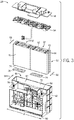
- FIG. 3 is a perspective view of an embodiment of the battery module 28.
- the battery module 28 illustrated in FIG. 3 includes a housing 42 that may be metallic (e.g., made from steel, aluminum, or another suitable metal) or may be polymeric (e.g., polypropylene, acrylonitrile butadiene styrene (ABS), a polystyrene (PS), a polyimide (PI), or another suitable polymer or plastic or combination thereof).
- ABS acrylonitrile butadiene styrene
- PS polystyrene
- PI polyimide
- the housing 42 holds one or more electrochemical cells 44 (e.g., lithium-ion cells, nickel metal hydride cells, lithium polymer cells, or any other suitable electrochemical cell) of the battery module 28.
- the electrochemical cells 44 are disposed in the housing 42 through a housing opening 46.
- a housing cover 48 is sealed over the housing opening 46 to completely enclose the electrochemical cells 44.
- the housing cover 48 may be manufactured from metallic or polymeric materials (e.g., polypropylene), similar to the housing 42.
- the electrochemical cells 44 described herein may be prismatic battery cells, where a prismatic battery cell, as defined herein, includes a prismatic case that is generally rectangular in shape.
- the prismatic casing is formed from a relatively inflexible, hard (e.g., metallic) material.
- each prismatic battery cell may include a top casing portion, where electrode terminals (e.g., positive and negative cell terminals) are located.
- electrode terminals e.g., positive and negative cell terminals
- One or more cell vents may also be located on the top casing portion.
- the prismatic cell casing also includes a bottom casing portion positioned opposite the top casing portion.
- First and second sides which may be straight or rounded, extend between the bottom and top casing portions in respective positions corresponding to the electrode terminals.
- First and second faces which may be flat or rounded, couple the first and second sides at opposing ends of each cell.
- the battery module 28 may include any number of the electrochemical cells 44, for example, between one and forty (e.g., six, twelve, twenty, or more electrochemical cells 44).
- the electrochemical cells 44 may be inserted into the housing 42 as a cell stack 50.
- each electrochemical cell 44 may be individually indexed in trays, cell slots, or a similar structure disposed in the housing 42.
- the housing 42 may include additional structures, such as spacers, to separate the electrochemical cells 44 or the cell stack 50 from other electrochemical cells 44 or cell stacks 50.
- the electrochemical cells 44 may be arranged in separate columns 52 of the cell stack 50.
- each column 52 may have half of a total number of the electrochemical cells 44 in the battery module 28.
- the battery module 28 includes three electrochemical cells 44 in each column 52 for a total of six electrochemical cells 44.
- a bus bar carrier 54 may be used to hold the electrochemical cells 44 in place within the housing 42.
- the bus bar 54 may include features that interface with a set number of the columns 52 in the battery module 28.
- the columnar arrangement of the electrochemical cells 44 may enable standardized dimensions (e.g., length and width) for the housing 42.
- the electrochemical cells 44 may provide power to the electric vehicle (e.g., xEV 10) through a pair of terminals 56 and 58 that connect the battery module 28 to an electrical load (e.g., circuit).
- the electrochemical cells 44 each have a positive electrode (e.g., a cathode) and a negative electrode (e.g., an anode) enclosed within a casing (e.g., packaging) of the respective electrochemical cell.
- the positive and negative electrodes each have electrode terminals 60 extending through a first cell surface 62.
- the electrodes may be made of a conductive collector material, such as, aluminum, stainless steel, nickel, copper, or tin, depending on the desired physical properties (e.g., yield strength, electrical resistivity, chemical compatibility, and so forth) and the active material on the electrodes.
- the electrodes are coated electrodes in which an electrode active material is coated onto the conductive collector material.
- LMO lithium metal oxides
- NMC lithium nickel cobalt manganese oxide
- NCA lithium nickel cobalt aluminum oxide
- LCO lithium cobalt oxide
- LMO-spinel lithium metal oxide spinel
- the negative electrode may be coated with anode active materials such as, but not limited to, graphite,
- the housing 42 may have standardized dimensions based on the voltage capacity of the battery module (e.g., 12V and 48V battery modules).
- the electrochemical cells 44 may have variable dimensions (e.g., a height of the cell stack 50).
- a first cell stack dimension 66 may be different from a second cell stack dimension 68.
- the electrochemical cells 44 in the cell stacks 50 may not conform to the housing 42.
- the different cell stack dimensions 66, 68 may result in gaps between a cell stack surface 70 and a housing inner surface 72. These gaps may allow undesirable movement of the undersized cell stacks 50 within the housing 42 during operation of the vehicle.
- the electrochemical cells 44 are secured to the housing 42 at the first cell surface 62 via the bus bar 54 (e.g., the bus bar 54 couples to the terminals 60 and the housing 42).
- a second cell surface 74 e.g., the surface substantially opposite the first cell surface6 62
- the undersized cell stacks 50 may move within the housing 42. Such movement may result in mechanical loading on, for example, the terminals 60 of the electrochemical cells 44. This loading may result in stress fractures at or near the terminals 60 and electrolyte leakage from the electrochemical cells 44.
- the terminals 60 of each electrochemical cell 44 are coupled to the bus bar carrier 54, which is secured to the housing 42 and/or the housing cover 48. Therefore, the electrochemical cells 44 may have limited movement at or near the first cell surface 62. However, because the second cell surface 74 is not secured to the housing 42 or other battery module component, undersized cell stacks 50 (e.g., cell stacks that do not conform to the housing 42) may move at or near the second cell surface 74. It is now recognized that movement of the second cell surface 74 may be blocked by placing an adhesive 78 between the second cell surface 74 and a heat sink 80 (e.g., a heat exchanger). As shown in FIG. 3 , the heat sink 80 is substantially opposite the opening 46 of the housing 42 and faces the second cell surface 74 when the electrochemical cells 44 are positioned within the housing 42.
- a heat sink 80 e.g., a heat exchanger
- a layer of the adhesive 78 may be disposed proximate to an interface surface between the electrochemical cells 44 and the heat exchanger (e.g., the heat sink 80) of the battery module 28.
- the layer of the adhesive 78 may be disposed between a surface of the electrochemical cells 44 (e.g., the second cell surface 74) and a surface of the heat exchanger.
- the layer of adhesive 78 between the surface 74 of the electrochemical cells 44 and the surface of the heat sink 80 may secure the electrochemical cells 44 to the heat sink 80, thereby decreasing movement of the electrochemical cells 44 during operation of the vehicle.
- the adhesive 78 may fill spaces between the electrochemical cells 44 that are near the interface surfaces of the electrochemical cells 44 and the heat sink 80.
- the layer of the adhesive 78 may conform to the electrochemical cells 44 to compensate for variability in dimensions (e.g., height) of the electrochemical cells 44.
- the adhesive 78 mitigates movement of the electrochemical cells 44 within the battery module 28 during operation of the vehicle by adhering the bottom sides (e.g., the second surface 74) of the electrochemical cells 44 to a heat sink surface 82 of the heat sink 80 of the battery module 28.
- the mechanical loading on certain battery components e.g., the electrode terminals 60
- battery durability may be increased and costs associated with replacement of the battery module 28 and/or the battery module components may be decreased.
- the heat sink 80 may be imbedded or otherwise attached to the housing 42, and may have a dimension 81 (e.g., length) that is approximately equal to an outermost dimension of the housing 42.
- the heat sink 80 is integrally formed within the housing 42.
- the heat sink 80 may be overmolded such that the heat sink 80 is an integral part of the housing 42.
- the adhesive 78 bonds (e.g., adheres) to both the second cell surface 74 and the heat sink surface 82 facing the second cell surface 74.
- the adhesive 78 may form a bond between the surfaces 74, 82, thereby coupling the electrochemical cells 44 and the heat sink 80.
- the electrochemical cells 44 may be secured within the housing 42 at both the first cell surface 62 (e.g., via the bus bar carrier 54) and the second cell surface 74 (e.g., via the adhesive 78). As such, undesirable movement of the electrochemical cells 44 during operation of the vehicle 10 enhance heat exchange between the electrochemical cells 44 and the heat sink 80.
- both the heat sink 80 and the cell casing of the electrochemical cells 44 may be manufactured from metallic materials such as, but not limited to, aluminum, copper, steel, metal alloys, and derivatives thereof, among others.
- the electrochemical cells may have a polymeric casing.
- the adhesive 78 may be an epoxy based adhesive.
- the adhesive 78 may cure (e.g., harden) and build strength over time. Accordingly, it may be desirable for the adhesive 78 to have bond strength suitable for adhering to metallic surfaces (e.g., aluminum surfaces). Accordingly, the adhesive 78 may have adhesion bond strength for metal-to-metal bonding greater than 5 megaPascals (MPa).
- the metal-to-metal adhesion bond strength of the adhesive 78 is between 5 MPa and 50 MPa (e.g., between 5 MPa and 40 MPa, between 10 MPa and 30 MPa, or between 20 MPa and 25 MPa). As such delamination (e.g., separation) of the adhesive 78 at the interface between the second cell surface 74 and heat sink surface 82 is decreased compared to adhesives that have bond strengths less than approximately 5 MPa.
- the adhesive 78 has a bonding shear strength and bonding tensile strength for aluminum-to-aluminum bonding that is greater than or equal to approximately 5 MPa at 25 degrees Celsius (°C).
- the bonding shear strength and the bonding tensile strength for aluminum-to-aluminum is between 5 MP and 50 MPa at 25 °C.
- This facilitates securing the casing of the electrochemical cells 44 to the heat sink 80.
- both the casing of the electrochemical cells 44 and the heat sink 80 are metallic (e.g., aluminum). Therefore, the bonding shear and tensile strength of the adhesive 78 is such that the adhesive 78 does not delaminate (e.g., separate) from the surfaces 74, 82.
- the bonding strength between 5 MPa and 50 MPa ensures that the cells 44 will remain bonded to the heat sink 80 of the module housing 42 under shock loads that are well beyond those that would typically be experienced during operation (e.g., a "worst-case” shock load), such as 150g (150 times the force of gravity).
- the surfaces 74, 82 may be treated to increase adhesion of the adhesive 78.
- the surfaces 74, 82 may be cleaned with solvents to remove residual contaminants (e.g., oils) resulting from manufacturing and/or handling of the electrochemical cells 44 and the heat sink 80.
- the surfaces 74, 82 may be texturized to increase a surface area of the surfaces 74, 82.
- the inner surface 72 of the module housing 42 and/or the second surface 74 of the battery cells 44 e.g., at their base
- the adhesive 78 may have a Shore D hardness of greater than or equal to 70 (e.g., between 70 and 90). It is believed that such Shore D hardness values may ensure that the adhesive 78 may remain stable during operation and prevent the adhesive 78 from displaying springlike properties while the module 22 is in use (e.g., while the xEV 10 is in motion).
- the battery module 28 may be exposed to elevated ambient temperatures (e.g., in excess of approximately 100 °C). Accordingly, to mitigate undesirable effects of the elevated temperatures (e.g., heat induced degradation), the adhesive 78 may be heat resistant. Additionally, the adhesive 78 may have a low coefficient of thermal expansion to minimize volume changes (e.g., due to temperature induced expansion and compression) of the adhesive 78 during operation of the vehicle 10. For example, the adhesive 78 may have a coefficient of thermal expansion less than or equal to approximately 40 parts per million (ppm)/°C). In certain embodiments, the coefficient of thermal expansion may be between approximately 0.5 ppm/°C and approximately 40 ppm/°C, which may facilitate maintaining the adhesive 78 within a desired volume during, for example, charging and discharging of the battery module 28.
- elevated ambient temperatures e.g., in excess of approximately 100 °C.
- the adhesive 78 may be heat resistant. Additionally, the adhesive 78 may have a low coefficient of thermal expansion to minimize volume changes (e.g., due to
- the heat sink 80 is configured to cool the electrochemical cells 44 by facilitating heat transfer between the electrochemical cells 44, fluid (e.g., air), and the housing 42. Therefore, because the adhesive 78 is between the surfaces 74, 82, it may be desirable for the adhesive 78 to have a suitable thermal conductivity to allow heat transfer between the electrochemical cells 44 and the heat sink 80. Accordingly, the adhesive 78 may have a thermal conductivity of greater than or equal to approximately 0.5 Watt/meter Kelvin (W/mK). By way of non-limiting example, the adhesive 78 may have a thermal conductivity of between approximately 0.5 W/mK and approximately 5 W/mK. In one embodiment, the adhesive 78 has a thermal conductivity of greater than or equal to 1.3 W/mK
- the adhesive 78 is an epoxy based adhesive. Therefore, the adhesive 78 may include an epoxy resin derived from bisphenols (e.g., Bisphenols A, F, and S), phenols, aliphatics (e.g., aliphatic alcohols and/or polyols), glycidylamine, glycidylethers, derivatives thereof, combinations thereof, or any other suitable epoxy resin having the adhesive properties disclosed herein. In certain embodiments, the adhesive 78 may include up to approximately 40 weight percent (wt %) of the epoxy resin. By way of example, the epoxy resin may be THERMOSET 340 EPOXY RESIN (available from LORD Corporation).
- the epoxy resin may also include additives and/or fillers to adjust a density and/or viscosity of the adhesive 78 based on a desired method of application and/or self leveling characteristic of the adhesive 78.
- the adhesive 78 may be applied to the second cell surface 74, the heat sink surface 82, or both before insertion of the electrochemical cells 44 in the housing 42.
- the adhesive 78 may be applied to the surfaces 74, 82 via a dispenser, a brush, dip coating (e.g., dipping the surface 74 in a solution of the adhesive 78), or any other suitable application method that applies the adhesive 78 to the surfaces 74, 82.
- the adhesive 78 may have a viscosity that is thick enough to remain on the surface 74, 82 without dripping (e.g., as a result of gravitational forces).
- the adhesive 78 may have a viscosity such that gravitational forces placed on the electrochemical cells 44 during insertion into the housing 42 do not cause the adhesive 78 to flow along the second cell surface 74 and/or drip before the second cell surface 74 abuts the heat sink surface 82.
- the viscosity of the adhesive 78 may not be so thick as to not allow the adhesive 78 to disperse and conform to the electrochemical cells 44 and the heat sink 80 when the second cell surface 74 is pushed up against the heat sink 80.
- the adhesive 78 may include between approximately 0.5 wt% and approximately 10 wt% of the filler. The amount of the filler in the adhesive 78 may depend on the desired viscosity and flow characteristics of the adhesive.
- Example fillers that may be used to achieve the desired viscosity may include carbon black, fumed silica, glass microspheres, combinations thereof, or any other suitable filler.
- the adhesive 78 may include a hardener that cures (e.g., cross-links) the epoxy resin over time.
- the epoxy resin may be mixed with the hardener before, during, or after application of the epoxy resin onto the surfaces 74, 82 to cure the epoxy resin and yield the adhesive 78.
- it may be desirable to select a hardener that enables curing of the adhesive 78 at low temperatures (e.g., less than or equal to 100 °C) within a desired amount of time.
- the adhesive 78 may have a full curing time of less than approximately 36 hours at a temperature of 25 °C.
- the adhesive 78 has a full curing time of approximately 24 hours at 25 °C.
- the term full curing time is the time it takes the adhesive 78 to reach the desired bond strength and hardness to fixedly secure the electrochemical cells 44 and the heat sink 80.
- the hardener may include any hardener suitable for use with an epoxy such as amines, acids, acid anhydrides, thiols, alcohols, phenols, or any other suitable low-temperature cure hardener.
- the hardener selected for curing the epoxy resin is such that a working life for the adhesive 78 is greater than or equal to 30 minutes.
- a working life of greater than or equal to 30 minutes may allow time to adjust the housing 42 and/or electrochemical cells 44 after insertion of the electrochemical cells 44 into the housing 42 before the adhesive 78 cures and is no longer sufficiently pliable.
- the working life for the adhesive may be between approximately 30 minutes and approximately 3 hours.
- the working life of the adhesive 78 is between approximately 60 minutes and approximately 2 hours.
- the working life of the adhesive 78 is the time, after mixing the epoxy resin and the hardener, that the adhesive 78 remains liquid and is workable to allow adjustment of the electrochemical cells 44 within the housing 42.
- the hardener may be THERMOSET HARDENER NO. 18 (available from LORD Corporation).
- the epoxy resin and the hardener may be a two-component system (e.g., a binary mixture).
- the epoxy resin and the hardener are in separate containers until ready for use.
- the epoxy resin and the hardener are mixed together to form the adhesive 78 prior to inserting the electrochemical cells 44 into the housing 42, as discussed in further detail below with reference to FIGS. 5-7 .
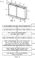
- FIG. 5 is a flow chart of method 100 that may be used to couple at least a portion of the electrochemical cells 44 to the heat sink 80.
- the method 100 begins by selecting (block 102) a desired epoxy and hardener combination and mixing (block 104) the selected epoxy resin with the selected hardener to form the adhesive 78.
- the adhesive 78 may be a two-component system. That is, the epoxy resin and the hardener are in separate containers until ready for use.
- the epoxy resin and the hardener may be mixed at a ratio of approximately 1:1 and approximately 3:2 by weight.
- the thermal epoxy resin to hardener ratio may be approximately 1:1, 1.5:1, 2:1, 2.2:1, 2.5:1, 3:1, 1:1.5, 1:2, and so forth up to 3:2.
- the adhesive 78 may have the desired working life and cure time discussed above.
- the method also includes applying (block 108) the adhesive 78 to the electrochemical cells 44, the heat sink 80, or both.
- the adhesive 78 may be applied to the surfaces 74, 82 via a dispenser, a brush, dip coating (e.g., dipping the surface 74 in a solution of the adhesive 78), or any other suitable application method.
- FIG. 6 illustrates the manner in which the adhesive 78 may be dispensed onto the heat sink surface 82 in accordance with block 108.
- the adhesive 78 may be applied at multiple locations along the dimension 81 of the heat sink 80.
- the adhesive 78 may be applied automatically or by a technician assembling the battery module 28.
- the adhesive 78 is applied as a discontinuous layer on the surface 74, 82.
- the adhesive 78 may be applied as separate droplets 110 onto the surface 74, 82.
- the adhesive 78 is applied as a continuous layer onto the surface 74, 82.
- the adhesive 78 may cover between approximately 25% and approximately 100% of a total surface area of the second cell surface 74 and/or the heat sink surface 82.
- the viscosity of the adhesive 78 is such that the adhesive 78 is easily dispersed along the surfaces 74, 82 (e.g., as shown by arrows 112) when the electrochemical cells 44 are inserted into the housing 42 (e.g., as shown by arrow 114).
- the method 100 further includes aligning (block 116) the electrochemical cells 44 with the opening 62 of the housing 42 and inserting (block 118) the electrochemical cells 44 into the opening 62 such that at least a portion of the second cell surfaces 74 abut the heat sink surface 82.
- This positioning pressure is also shown in FIG. 6.
- FIG. 6 illustrates the interface between the electrochemical cells 44 and the heat sink 80.
- the electrochemical cells 44 exert a force 120 on the heat sink surface 82 such that adhesive 78 is dispersed along the surfaces 74, 82 and forms a continuous adhesive layer 122 between the surfaces 74, 82.
- the force 120 may disperse the adhesive 78 into gaps (e.g., a gap 124) between the cells stacks 50 and/or between the interior surface 72 of the housing 42 and the cell stack surface 70.
- gaps e.g., a gap 124
- the adhesive 78 may be dispersed a distance 123 along side surfaces 125 of the electrochemical cells 44.
- the adhesive 78 may cover between approximately 1% and approximately 5% of the side surfaces 125 of the electrochemical cells 44.
- the adhesive 78 may be localized at the interface of the electrochemical cells 44 and the heat sink 80.
- the adhesive 78 may be self-leveling. That is, once the adhesive 78 is applied to the surface 74, 82, the adhesive 78 may disperse on the surfaces 74, 82, 125 without the use of tools to spread the adhesive 78 along the surface 74, 82 and into the gaps (e.g., the gap 124). Therefore, the second cell surface 74 may not need to abut the heat sink surface 82 to disperse the adhesive 78 along the surfaces 74, 82 and the gaps.
- the adhesive 78 may be heated to facilitate dispersion along the surfaces 74, 82.
- heat 128 is applied to the battery module 28.
- the heat 128 may be applied to the heat sink 80, the electrochemical cells 44, or both, before, during, or after application of the adhesive 78 onto the surface 74, 82.
- the heat 128 is applied to the surface 74, 82 (e.g., via the electrochemical cells 44 or the heat sink 80) that is facing the surface 74, 82 where the adhesive 78 is applied. This may be useful for dispersing and accelerating the cure time of the adhesive 78 after the surfaces 74, 82 are in contact with one another.
- the heat 128 may be applied to the same surface 74, 82 where the adhesive 78 is applied. This may be useful, for example, when the viscosity of the adhesive 78 is above a desired range. Further, in some embodiments, the heat 128 is applied to both the surfaces 74, 82 concurrently. The heat 128 may decrease the viscosity of the adhesive 78 such that a fluidity of the adhesive 78 increases compared to a fluidity of the adhesives 78 that are not heated.
- the method 100 further includes adjusting (block 130) a position of the electrochemical cells 44 relative to the heat sink 80 before the adhesive 78 fully cures (e.g., during the working life of the adhesive 78).
- the electrochemical cells 44 may be adjusted to align the terminals 60 with other components (e.g., the bus bar 54 and/or housing 48) of the battery module 28.
- the adhesive 78 may have a working life of greater than or equal to approximately 60 minutes to allow adjustments of the electrochemical cells 44 after insertion into the housing 42.
- the method 100 also includes curing (block 132) the adhesive 78 to bond the electrochemical cells 44 to the heat sink 80.
- the adhesive 78 begins to cure and develop bond strength over time.
- the adhesive 78 bonds to the surfaces 74, 82 and secures the electrochemical cells 44 to the heat sink 80.
- This securement including under the operating conditions of the battery module 28, blocks movement of the 50 of the electrochemical cells 44 within the housing 42. As such, stress on the terminals 60 and/or first cell surface 62 of the electrochemical cells 44 that may be caused by the movement of the cell stacks 50 within the housing 42 may be mitigated.
- heat may be applied to accelerate curing of the adhesive 28.
- the heat sink 80 may be coupled to a heat source that may be used to apply indirect heat to the adhesive 78 (e.g., via the heat sink 80), thereby accelerating curing of the adhesive 78.
- the heat may be applied at any time after the electrochemical cells 44 are properly positioned within the housing 42.
- the adhesive may be a radiation-activated epoxy resin.
- the adhesive 78 may not include a hardener to initiate curing. Rather, the adhesive 78 may be cured using radiation (e.g., ultraviolet (UV) radiation). Upon exposure to the radiation, the adhesive begins to harden.
- UV ultraviolet
- one or more of the disclosed embodiments may provide one or more technical effects useful in the manufacture of the battery module and associated use of aluminum-to-aluminum adhesives.
- certain embodiments of the present approach may facilitate assembly of the battery modules during manufacturing.
- the epoxy adhesive may couple the electrochemical cells to a heat sink of the battery system.
- the undesirable movement of the electrochemical cells within the housing, in particular a portion of the electrochemical cells that is opposite the electrode terminals, may be mitigated. Therefore, durability of the battery module may be increased, thereby reducing costs associated with replacement of the battery module compared to battery modules that do not have the disclosed adhesive.
- the technical effects and technical problems in the specification are examples and are not limiting. It should be noted that the embodiments described in the specification may have other technical effects and can solve other technical problems.
Landscapes
- Chemical & Material Sciences (AREA)
- Chemical Kinetics & Catalysis (AREA)
- Electrochemistry (AREA)
- General Chemical & Material Sciences (AREA)
- Engineering & Computer Science (AREA)
- Manufacturing & Machinery (AREA)
- Materials Engineering (AREA)
- Organic Chemistry (AREA)
- Aviation & Aerospace Engineering (AREA)
- Secondary Cells (AREA)
- Battery Mounting, Suspending (AREA)
Claims (14)
- Batteriemodul (28), umfassend:- ein Gehäuse (42) mit einer Öffnung (46);- eine elektrochemische Zelle (44), die in dem Gehäuse (42) angeordnet ist, wobei die elektrochemische Zelle (44) eine erste Zellenoberfläche (62) mit Elektrodenanschlüssen (60) und eine zweite Zellenoberfläche (74), die der ersten Zellenoberfläche (62) im Wesentlichen gegenüberliegt, umfasst;- eine Wärmesenke (80), die mit dem Gehäuse (42) integral ist und im Wesentlichen gegenüber der Öffnung (46) des Gehäuses (42) angeordnet ist; und- einen wärmeleitfähigen Klebstoff (78), der an die zweite Zellenoberfläche (74) und eine Wärmesenkenoberfläche (82), die zu der zweiten Zellenoberfläche (74) zeigt, gebunden ist, wobei der wärmeleitfähige Klebstoff (78) eine Bindungsscherfestigkeit und eine Bindungszugfestigkeit zwischen der elektrochemischen Zelle (44) und der Wärmesenke (80) von zwischen 5 Megapascal (MPa) und 50 MPa bei 25 Grad Celsius aufweist.
- Batteriemodul (28) gemäß Anspruch 1,
wobei der wärmeleitfähige Klebstoff (78) ein Gemisch von einem Epoxidharz und einem Härter umfasst, wobei das Gemisch dafür gestaltet ist, innerhalb von weniger als oder gleich 24 Stunden zu härten. - Batteriemodul (28) gemäß Anspruch 2,
wobei das Gemisch ein Verhältnis von zwischen 1:1 und 2:1 Epoxidharz zu Härter aufweist. - Batteriemodul (28) gemäß Anspruch 2 oder 3,
wobei das Gemisch eine Viskosität von zwischen 40.000 Centipoise (cP) und 50.000 cP vor dem Härten aufweist. - Batteriemodul (28) gemäß einem der Ansprüche 1 bis 4,
wobei der wärmeleitfähige Klebstoff (78) ein strahlungsaktiviertes Epoxidharz umfasst. - Batteriemodul (28) gemäß einem der Ansprüche 1 bis 5,
wobei der wärmeleitfähige Klebstoff (78) eine Wärmeleitfähigkeit von zwischen 0,5 Watt/Meter.Kelvin (W/mK) und 2,0 W/mK aufweist. - Batteriemodul (28) gemäß einem der Ansprüche 1 bis 6,
wobei der wärmeleitfähige Klebstoff (78) selbstverlaufend ist und/oder wobei der wärmeleitfähige Klebstoff (78) eine Verarbeitbarkeitsdauer von zwischen 1 Stunde und 3 Stunden aufweist; und/oder wobei der Klebstoff (78) eine Härte von gleich 80 Shore D aufweist; und/oder
wobei der Klebstoff (78) wärmebeständig ist. - Verfahren zur Herstellung eines Batteriemoduls (28) gemäß einem der Ansprüche 1 bis 7, umfassend:- Aufbringen eines Klebstoffs (78) auf ein Gehäuse (42) des Batteriemoduls (28) an einer Grenzfläche zwischen einer elektrochemischen Zelle (44) und einer Wärmesenke (80) des Batteriemoduls (28), wobei der Klebstoff (78) eine Viskosität von zwischen 40.000 Centipoise (cP) und 50.000 cP und eine Verarbeitbarkeitsdauer von zwischen 1 Stunde und 3 Stunden aufweist;- nach dem Aufbringen des Klebstoffs (78) Einführen der elektrochemischen Zelle (44) in die Öffnung (46) in Richtung auf die Wärmesenke (80); und- Härten des Klebstoffs (78), um die elektrochemischen Zellen an der Grenzfläche an der Wärmesenke (80) zu befestigen,wobei der gehärtete Klebstoff (78) eine Bindungsscherfestigkeit und eine Bindungszugfestigkeit zwischen der elektrochemischen Zelle (44) und der Wärmesenke (80) von zwischen 5 MPa und 50 MPa bei 25 Grad Celsius aufweist.
- Verfahren gemäß Anspruch 8,
wobei der Klebstoff (78) eine Wärmeleitfähigkeit von 0,5 Watt/Meter.Kelvin (W/mK) und 2,0 W/mK aufweist. - Verfahren gemäß Anspruch 8 oder 9,
wobei der Klebstoff (78) eine Härte von gleich 80 Shore D nach dem Härten aufweist. - Verfahren gemäß einem der Ansprüche 8 bis 10,
wobei der Klebstoff (78) ein Zweikomponentensystem ist, das ein Epoxidharz und einen Härter umfasst. - Verfahren gemäß Anspruch 11,
umfassend Mischen des Epoxidharzes und des Härters in einem Verhältnis von zwischen 1:1 und 2:1 Epoxidharz zu Härter vor dem Aufbringen des Klebstoffs (78) auf das Gehäuse (42). - Verfahren gemäß einem der Ansprüche 8 bis 12,
wobei der Klebstoff (78) ein Ultraviolettlicht-härtbares Epoxidharz umfasst; und/oder
wobei die Viskosität so ist, dass der Klebstoff (78) selbstverlaufend ist; und/oder
wobei der Klebstoff (78) eine Aluminium-an-Aluminium-Bindungsscherfestigkeit und Bindungszugfestigkeit von zwischen 5 Megapascal (MPa) und 50 MPa aufweist. - Verfahren gemäß einem der Ansprüche 8 bis 13,
wobei die elektrochemische Zelle und die Wärmesenke (80) jeweils eine metallische Oberfläche an der Grenzfläche umfassen und wobei die metallische Oberfläche Aluminium, Kupfer oder Stahl umfasst.
Applications Claiming Priority (5)
| Application Number | Priority Date | Filing Date | Title |
|---|---|---|---|
| US201562146811P | 2015-04-13 | 2015-04-13 | |
| US201562146763P | 2015-04-13 | 2015-04-13 | |
| US201562146816P | 2015-04-13 | 2015-04-13 | |
| US14/815,447 US10700317B2 (en) | 2015-04-13 | 2015-07-31 | Cell to heat sink thermal adhesive |
| PCT/US2016/018449 WO2016167873A1 (en) | 2015-04-13 | 2016-02-18 | Cell to heat sink thermal adhesive |
Publications (2)
| Publication Number | Publication Date |
|---|---|
| EP3284124A1 EP3284124A1 (de) | 2018-02-21 |
| EP3284124B1 true EP3284124B1 (de) | 2019-04-10 |
Family
ID=57112836
Family Applications (3)
| Application Number | Title | Priority Date | Filing Date |
|---|---|---|---|
| EP16713148.1A Pending EP3284123A1 (de) | 2015-04-13 | 2016-02-18 | Thermisches epoxid und positionierung von elektrochemischen zellen |
| EP16715647.0A Active EP3284124B1 (de) | 2015-04-13 | 2016-02-18 | Zelle an einem kühlkörperwärmeleitkleber |
| EP16713147.3A Active EP3284122B1 (de) | 2015-04-13 | 2016-02-18 | Klebeband zur positionierung von batteriezellen in einem batteriemodul |
Family Applications Before (1)
| Application Number | Title | Priority Date | Filing Date |
|---|---|---|---|
| EP16713148.1A Pending EP3284123A1 (de) | 2015-04-13 | 2016-02-18 | Thermisches epoxid und positionierung von elektrochemischen zellen |
Family Applications After (1)
| Application Number | Title | Priority Date | Filing Date |
|---|---|---|---|
| EP16713147.3A Active EP3284122B1 (de) | 2015-04-13 | 2016-02-18 | Klebeband zur positionierung von batteriezellen in einem batteriemodul |
Country Status (4)
| Country | Link |
|---|---|
| US (7) | US10403869B2 (de) |
| EP (3) | EP3284123A1 (de) |
| CN (5) | CN107801422B (de) |
| WO (3) | WO2016167873A1 (de) |
Cited By (2)
| Publication number | Priority date | Publication date | Assignee | Title |
|---|---|---|---|---|
| EP3987605A1 (de) * | 2019-06-18 | 2022-04-27 | Audi AG | Verfahren zum einbringen einer wärmeleitfähigen füllmasse mit variablem anteil an füllstoff, batteriemodulvorrichtung und anlage zum einbringen von füllmasse |
| WO2024186479A1 (en) * | 2023-03-07 | 2024-09-12 | Apple Inc. | Structural battery pack with adhesive and gap fillers |
Families Citing this family (68)
| Publication number | Priority date | Publication date | Assignee | Title |
|---|---|---|---|---|
| US10403869B2 (en) | 2015-04-13 | 2019-09-03 | Cps Technology Holdings, Llc | Adhesive tape for positioning battery cells in a battery module |
| US10116018B2 (en) | 2016-01-07 | 2018-10-30 | GM Global Technology Operations LLC | Cure in place thermal interface material |
| US10700395B2 (en) | 2016-08-09 | 2020-06-30 | Nio Usa, Inc. | Battery module housing having an integrally-formed cooling plate |
| JP6583219B2 (ja) * | 2016-11-15 | 2019-10-02 | トヨタ自動車株式会社 | 電池モジュール |
| DE102016225192A1 (de) * | 2016-12-15 | 2018-06-21 | Robert Bosch Gmbh | Wärmeverteiler für eine Batterie |
| CN110392944A (zh) | 2017-03-07 | 2019-10-29 | 远景Aesc日本有限公司 | 电池组的制造方法 |
| US10601090B2 (en) * | 2017-04-28 | 2020-03-24 | Nio Usa, Inc. | Using a spacer to block path of thermally conductive structural adhesive in lithium ion cells |
| WO2018232335A1 (en) * | 2017-06-16 | 2018-12-20 | Kruszelnicki Martin | Battery pack module |
| KR102461577B1 (ko) * | 2017-07-17 | 2022-11-01 | 삼성에스디아이 주식회사 | 이차전지 모듈 |
| DE102017008102A1 (de) * | 2017-08-29 | 2019-02-28 | Carl Freudenberg Kg | Energiespeichersystem |
| WO2019071184A1 (en) * | 2017-10-06 | 2019-04-11 | Johnson Controls Technology Company | LITHIUM ION BATTERY |
| JP6965717B2 (ja) * | 2017-12-13 | 2021-11-10 | トヨタ自動車株式会社 | 電池パックの製造方法 |
| DE102018208027A1 (de) * | 2018-05-23 | 2019-07-11 | Audi Ag | Batterieanordnung für ein Fahrzeug |
| DE102018113815B4 (de) * | 2018-06-11 | 2020-02-13 | Carl Freudenberg Kg | Energiespeichersystem |
| DE102018210152A1 (de) | 2018-06-21 | 2019-12-24 | Bayerische Motoren Werke Aktiengesellschaft | Fahrzeug mit einem Hochvoltspeicher |
| DE102018210151A1 (de) * | 2018-06-21 | 2019-12-24 | Bayerische Motoren Werke Aktiengesellschaft | Fahrzeug mit einem Hochvoltspeicher |
| EP3618171B1 (de) * | 2018-08-30 | 2021-02-24 | ABB Schweiz AG | Thermisch entkoppelte batteriezellengruppen |
| US11114715B2 (en) * | 2018-12-06 | 2021-09-07 | Ford Global Technologies, Llc | Enclosure assemblies with improved electromagnetic compatibility |
| US11081898B2 (en) * | 2018-12-17 | 2021-08-03 | Microsoft Technology Licensing, Llc | Electrical battery de-bonding |
| CN111384314B (zh) * | 2018-12-29 | 2021-01-19 | 宁德时代新能源科技股份有限公司 | 电池箱 |
| CN110190211B (zh) | 2018-12-29 | 2020-03-31 | 比亚迪股份有限公司 | 电池托盘、动力电池包及车辆 |
| CN111384328A (zh) | 2018-12-29 | 2020-07-07 | 比亚迪股份有限公司 | 电池托盘、动力电池包及车辆 |
| JP2022517214A (ja) * | 2019-01-09 | 2022-03-07 | ビーワイディー カンパニー リミテッド | 単電池、動力電池パック及び電気自動車 |
| DE102019102003B4 (de) * | 2019-01-28 | 2020-11-19 | Lisa Dräxlmaier GmbH | Verfahren und system zur thermischen anbindung einer wärmequelle eines batteriesystems an eine wärmesenke eines batteriesystems |
| CN113892210B (zh) * | 2019-02-08 | 2024-07-26 | Cps科技控股有限公司 | 具有被动散热器的电池系统 |
| USD998560S1 (en) * | 2019-02-08 | 2023-09-12 | Cps Technology Holdings Llc | Battery housing |
| DE102019103570B4 (de) * | 2019-02-13 | 2022-12-22 | Dr. Ing. H.C. F. Porsche Aktiengesellschaft | Verfahren zum Herstellen einer Traktionsbatterie eines Kraftfahrzeugs |
| KR102455471B1 (ko) * | 2019-02-18 | 2022-10-14 | 주식회사 엘지에너지솔루션 | 배터리 셀, 이를 포함하는 배터리 모듈, 배터리 랙 및 전력 저장 장치 |
| KR102829347B1 (ko) * | 2019-04-26 | 2025-07-02 | 현대자동차주식회사 | 차량용 배터리 냉각 장치 |
| JP7462663B2 (ja) * | 2019-06-12 | 2024-04-05 | エルジー エナジー ソリューション リミテッド | 電池モジュール、その製造方法および電池モジュールを含む電池パック |
| KR102767817B1 (ko) * | 2019-07-02 | 2025-02-14 | 주식회사 엘지에너지솔루션 | 밀착형 쿨링플레이트를 포함하는 배터리 팩 및 이를 포함하는 디바이스 |
| DE102019210439A1 (de) * | 2019-07-15 | 2021-01-21 | Audi Ag | Verfahren zum Montieren einer Batterie, Batterie sowie Kraftfahrzeug mit einer solchen Batterie |
| KR102771555B1 (ko) * | 2019-08-07 | 2025-02-20 | 주식회사 엘지에너지솔루션 | 상부 냉각 방식 배터리 팩 |
| CN112310525A (zh) * | 2019-08-14 | 2021-02-02 | 宁德时代新能源科技股份有限公司 | 电池箱 |
| CN112331963A (zh) * | 2019-09-19 | 2021-02-05 | 宁德时代新能源科技股份有限公司 | 壳体、二次电池、电池包、车辆及二次电池的制造方法 |
| KR102798546B1 (ko) * | 2019-10-18 | 2025-04-18 | 주식회사 엘지에너지솔루션 | 전지 모듈 |
| DE102019129067B3 (de) * | 2019-10-28 | 2021-04-01 | Lisa Dräxlmaier GmbH | Verfahren und vorrichtung zum verbinden von komponenten einer batterie |
| DE102019130385A1 (de) * | 2019-11-11 | 2021-05-12 | Audi Ag | Traktionsbatterie sowie Verfahren zur Montage einer solchen Traktionsbatterie |
| KR102514497B1 (ko) * | 2019-11-13 | 2023-03-24 | 주식회사 엘지에너지솔루션 | 전지 모듈 및 이를 포함하는 전지 팩 |
| KR102931768B1 (ko) * | 2019-11-13 | 2026-02-25 | 주식회사 엘지에너지솔루션 | 배터리 모듈, 이러한 배터리 모듈의 제조 방법 및 이러한 배터리 모듈을 포함하는 배터리 팩 및 자동차 |
| DE102020111243A1 (de) | 2020-04-24 | 2021-10-28 | Bayerische Motoren Werke Aktiengesellschaft | Lithiumionenbatterie und Batteriemodul |
| CN121939099A (zh) | 2020-04-30 | 2026-04-28 | 宁德时代新能源科技股份有限公司 | 电池模组、装置、电池包以及电池模组的制造方法和设备 |
| DE102020115897A1 (de) | 2020-06-17 | 2021-12-23 | Bayerische Motoren Werke Aktiengesellschaft | Batterie für ein Kraftfahrzeug und Kraftfahrzeug |
| EP4068473B1 (de) * | 2020-07-03 | 2026-03-04 | LG Energy Solution, Ltd. | Batteriepack mit struktur zur verhinderung von wärmediffusion zwischen benachbarten batteriemodulen sowie energiespeichersystem (ess) und fahrzeug damit |
| WO2022021135A1 (zh) | 2020-07-29 | 2022-02-03 | 宁德时代新能源科技股份有限公司 | 电池模组、电池包、装置以及电池模组的制造方法和制造设备 |
| WO2022030821A1 (ko) * | 2020-08-05 | 2022-02-10 | 주식회사 엘지에너지솔루션 | 전지 모듈, 이를 포함하는 전지 팩 및 전지 모듈 운반 방법 |
| KR102807505B1 (ko) * | 2020-08-21 | 2025-05-13 | 주식회사 엘지에너지솔루션 | 전지 모듈, 이를 포함하는 전지 팩 및 전지 팩 제조 방법 |
| KR102864265B1 (ko) * | 2020-09-04 | 2025-09-26 | 주식회사 엘지에너지솔루션 | 전지팩 조립 시스템 및 이를 이용한 전지팩의 조립 방법 |
| CN121238070A (zh) * | 2020-09-30 | 2025-12-30 | 宁德时代新能源科技股份有限公司 | 电池、装置、电池的制备方法以及制备装置 |
| EP4064435A4 (de) | 2020-09-30 | 2024-04-24 | Contemporary Amperex Technology Co., Limited | Batterie, vorrichtung sowie herstellungsverfahren und vorrichtung zur herstellung einer batterie |
| EP4064436A4 (de) | 2020-09-30 | 2023-05-03 | Contemporary Amperex Technology Co., Limited | Batterie, vorrichtung und herstellungsverfahren und gerät für eine batterie |
| CN115699406B (zh) | 2020-11-17 | 2024-10-01 | 宁德时代新能源科技股份有限公司 | 电池、使用电池的装置、电池的制备方法和制备设备 |
| EP4044287A4 (de) | 2020-12-24 | 2022-12-28 | Contemporary Amperex Technology Co., Limited | Batteriemodul und herstellungsverfahren und vorrichtung dafür, batteriesatz und energieverbrauchsvorrichtung |
| US11165120B1 (en) * | 2021-02-17 | 2021-11-02 | High Tech Battery Inc. | Energy storage module |
| DE102021115705B3 (de) * | 2021-06-17 | 2022-06-30 | Dr. Ing. H.C. F. Porsche Aktiengesellschaft | Batterie für ein Kraftfahrzeug |
| DE102021207410A1 (de) * | 2021-07-13 | 2023-01-19 | Robert Bosch Gesellschaft mit beschränkter Haftung | Verfahren zur Herstellung eines Batteriemoduls und Batteriemodul |
| ES3065086T3 (en) | 2021-07-30 | 2026-05-04 | Contemporary Amperex Technology Hong Kong Ltd | Battery group, battery pack and electric apparatus |
| WO2023070042A1 (en) * | 2021-10-20 | 2023-04-27 | Arcimoto, Inc. | Battery system |
| KR20230141339A (ko) * | 2022-03-31 | 2023-10-10 | 에스케이온 주식회사 | 배터리 모듈 및 이를 포함하는 디바이스 |
| EP4345994A4 (de) * | 2022-04-27 | 2025-02-12 | LG Energy Solution, Ltd. | Batteriemodul, batteriepack und fahrzeug damit |
| US20250202002A1 (en) * | 2022-06-30 | 2025-06-19 | Dow Global Technologies Llc | Thermally triggered primer and thermosetting adhesive multilayer composition for detachment of ev battery pack |
| US12438225B2 (en) * | 2023-01-12 | 2025-10-07 | GM Global Technology Operations LLC | Battery assemblies, motor vehicles, and methods fixturing battery components utilizing fast-set adhesives |
| US20240347844A1 (en) * | 2023-04-14 | 2024-10-17 | GM Global Technology Operations LLC | Structural senseline assembly with split interconnect board for battery cell array |
| US20240413455A1 (en) * | 2023-06-07 | 2024-12-12 | The Noco Company | Systems and Methods for Lithium-Ion Battery Durability |
| DE102023117128A1 (de) | 2023-06-29 | 2025-01-02 | Audi Aktiengesellschaft | Verfahren und Montagevorrichtung zum Montieren eines Batteriemoduls an einem Gehäusebauteil |
| US20250135730A1 (en) * | 2023-10-26 | 2025-05-01 | GM Global Technology Operations LLC | Cure acceleration of thermal interface adhesives via adjacent component heating |
| KR20260000824A (ko) * | 2024-06-26 | 2026-01-05 | 삼성에스디아이 주식회사 | 배터리 모듈 |
| DE102024206833B4 (de) | 2024-07-22 | 2026-03-26 | Powerco Se | Montageverfahren für eine Batteriezelle und Batteriezelle |
Family Cites Families (75)
| Publication number | Priority date | Publication date | Assignee | Title |
|---|---|---|---|---|
| US5483143A (en) | 1994-04-29 | 1996-01-09 | Hughes Aircraft Company | Composite core designed for inductive coupled transformer probes |
| US6087036A (en) | 1997-07-25 | 2000-07-11 | 3M Innovative Properties Company | Thermal management system and method for a solid-state energy storing device |
| US5977746A (en) | 1998-07-21 | 1999-11-02 | Stryker Corporation | Rechargeable battery pack and method for manufacturing same |
| KR100337539B1 (ko) | 1998-12-24 | 2002-07-18 | 성재갑 | 함몰부를 함유한 면을 포함하는 각형 캔을이용한 리튬 이온 전지 |
| JP3940342B2 (ja) * | 2002-09-13 | 2007-07-04 | 日産自動車株式会社 | 二次電池モジュール及びその製造方法 |
| EP1518899A3 (de) * | 2003-09-18 | 2005-08-03 | Fuji Photo Film Co., Ltd. | Photohärtbare Klebstoffe und Verfestigungsverfahren |
| WO2005043650A2 (en) | 2003-10-28 | 2005-05-12 | Johnson Controls Technology Company | Battery system with improved heat dissipation |
| EP2450981B1 (de) * | 2004-12-24 | 2014-03-19 | Lg Chem, Ltd. | Sekundärbatteriemodul |
| JP4749774B2 (ja) | 2005-06-16 | 2011-08-17 | 本田技研工業株式会社 | 組電池 |
| JP4561542B2 (ja) | 2005-09-02 | 2010-10-13 | ソニー株式会社 | 二次電池 |
| WO2007053992A1 (en) | 2005-11-08 | 2007-05-18 | Byd Company Limited | A heat dissipating device for a battery pack, and a battery pack using the same |
| KR100948970B1 (ko) | 2006-03-13 | 2010-03-23 | 주식회사 엘지화학 | 완충부재가 설치되어 있는 중대형 전지모듈 |
| KR100942986B1 (ko) | 2006-03-21 | 2010-02-17 | 주식회사 엘지화학 | 전지셀 사이에 접착부재가 부착되어 있는 전지모듈 |
| KR101067627B1 (ko) | 2006-11-13 | 2011-09-26 | 주식회사 엘지화학 | 콤팩트한 구조와 우수한 방열 특성의 전지모듈 |
| JP2008204982A (ja) | 2007-02-16 | 2008-09-04 | Matsushita Electric Ind Co Ltd | キャパシタユニット |
| KR100824865B1 (ko) | 2007-03-16 | 2008-04-23 | 삼성에스디아이 주식회사 | 이차전지 |
| US20090023056A1 (en) | 2007-07-18 | 2009-01-22 | Tesla Motors, Inc. | Battery pack thermal management system |
| JP4508221B2 (ja) * | 2007-08-27 | 2010-07-21 | 豊田合成株式会社 | 組電池装置 |
| KR100998301B1 (ko) | 2007-11-08 | 2010-12-03 | 삼성에스디아이 주식회사 | 배터리 팩 및 이를 구비하는 전자기기 |
| FR2929760B1 (fr) | 2008-04-08 | 2010-10-01 | Vehicules Electr Soc D | Batterie electrique comprenant des elements generateurs souples et un systeme de conditionnement mecanique et thermique desdits elements |
| JP5028346B2 (ja) * | 2008-06-27 | 2012-09-19 | Fdk株式会社 | 蓄電装置 |
| KR101004006B1 (ko) | 2008-08-06 | 2010-12-31 | 주식회사 엘지화학 | 전지팩의 제조방법 및 제조 공정 점검 시스템 |
| JP5564048B2 (ja) * | 2008-09-10 | 2014-07-30 | ダウ グローバル テクノロジーズ エルエルシー | 反応性接着剤を基材に結合させるための改良されたプロセス |
| DE102008059960B4 (de) | 2008-12-02 | 2013-07-04 | Daimler Ag | Verfahren zur Herstellung einer Batterie, nach dem Verfahren hergestellte Batterie und Batterieverbund aus zwei derartigen Batterien |
| US20100151308A1 (en) | 2008-12-12 | 2010-06-17 | Tesla Motors, Inc. | Increased resistance to thermal runaway through differential heat transfer |
| WO2010114317A2 (ko) | 2009-04-01 | 2010-10-07 | 주식회사 엘지화학 | 우수한 방열 특성의 전지모듈 및 중대형 전지팩 |
| US20100291419A1 (en) | 2009-05-15 | 2010-11-18 | Sinoelectric Powertrain Corporation | Battery pack heat exchanger, systems, and methods |
| JP5451211B2 (ja) * | 2009-06-26 | 2014-03-26 | パナソニック株式会社 | 蓄電ユニット |
| US9263724B2 (en) | 2009-10-12 | 2016-02-16 | Samsung Sdi Co., Ltd. | Battery pack |
| JP5740103B2 (ja) * | 2009-10-19 | 2015-06-24 | 日東電工株式会社 | 熱伝導部材、及びそれを用いた組電池装置 |
| WO2011076936A1 (de) | 2009-12-23 | 2011-06-30 | Magna Steyr Fahrzeugtechnik Ag & Co Kg | Akkumulator mit spannungserzeugenden zellen und einem dazwischen angeordneten schalenförmigen zwischenelement |
| US8057630B2 (en) * | 2010-03-02 | 2011-11-15 | Tesla Motors, Inc. | Selective cure of adhesive in modular assemblies |
| US20130023605A1 (en) * | 2010-03-31 | 2013-01-24 | Dow Global Technologies Llc | Curable compositions |
| WO2011126161A1 (ko) | 2010-04-07 | 2011-10-13 | 주식회사 이아이지 | 이차전지 모듈 |
| US9263713B2 (en) * | 2010-05-26 | 2016-02-16 | Samsung Sdi Co., Ltd. | Battery pack |
| KR101289282B1 (ko) | 2010-05-28 | 2013-07-24 | 주식회사 엘지화학 | 콤팩트한 구조의 전지팩 |
| JP5194070B2 (ja) | 2010-07-20 | 2013-05-08 | 日立ビークルエナジー株式会社 | 二次電池 |
| JP5343048B2 (ja) | 2010-07-29 | 2013-11-13 | 日立ビークルエナジー株式会社 | 蓄電モジュールおよび蓄電装置 |
| KR101223520B1 (ko) * | 2010-11-10 | 2013-01-17 | 로베르트 보쉬 게엠베하 | 전지 모듈 |
| JP2012160298A (ja) | 2011-01-31 | 2012-08-23 | Nitto Denko Corp | 組電池装置 |
| WO2012117681A1 (ja) | 2011-02-28 | 2012-09-07 | 三洋電機株式会社 | 電池モジュールおよび電池モジュールの製造方法 |
| WO2012125115A1 (en) | 2011-03-15 | 2012-09-20 | Effpower Ab | Battery module, vehicle, electric device and method |
| FR2972857B1 (fr) | 2011-03-18 | 2013-04-19 | Commissariat Energie Atomique | Procede de determination d'etat de fin de charge d'un accumulateur li-ion a electrode negative en alliage, accumulateur et assemblage d'accumulateurs associes |
| JP2012212608A (ja) | 2011-03-31 | 2012-11-01 | Nec Energy Devices Ltd | 電池パック |
| JP5831924B2 (ja) | 2011-03-31 | 2015-12-09 | Necエナジーデバイス株式会社 | 電池パック |
| CN103718374B (zh) | 2011-04-15 | 2017-11-03 | 约翰逊控制技术有限责任公司 | 具有外部热管理系统的电池系统 |
| WO2012147801A1 (ja) | 2011-04-27 | 2012-11-01 | 三洋電機株式会社 | 電源装置及び電源装置を備える車両 |
| JP6010326B2 (ja) * | 2011-06-02 | 2016-10-19 | 株式会社東芝 | 二次電池装置、二次電池装置の製造方法 |
| US20120308873A1 (en) * | 2011-06-02 | 2012-12-06 | Masahiro Sekino | Secondary battery apparatus and method of manufacturing secondary battery apparatus |
| KR101308592B1 (ko) | 2011-07-21 | 2013-09-13 | 한화케미칼 주식회사 | 방열특성을 갖는 전지용 포장재 |
| US9287594B2 (en) | 2011-11-24 | 2016-03-15 | Toyota Jidosha Kabushiki Kaisha | Electric storage apparatus and vehicle |
| CN102420297A (zh) | 2011-12-02 | 2012-04-18 | 苏州冠硕新能源有限公司 | 电池模组框架以及应用该框架的电池组件 |
| JP5580282B2 (ja) | 2011-12-09 | 2014-08-27 | 本田技研工業株式会社 | バッテリの冷却装置 |
| KR101877569B1 (ko) | 2012-03-05 | 2018-07-11 | 삼성에스디아이 주식회사 | 이차 전지 |
| US20130236768A1 (en) | 2012-03-08 | 2013-09-12 | Lg Chem, Ltd. | Battery pack of stair-like structure |
| US9368843B2 (en) * | 2012-06-04 | 2016-06-14 | Graftech International Holdings, Inc. | Battery pack assembly |
| US9225035B1 (en) | 2012-06-06 | 2015-12-29 | KleenSpeed Technologies Inc. | Low profile battery module and improved thermal interface |
| KR101392799B1 (ko) | 2012-06-07 | 2014-05-14 | 주식회사 엘지화학 | 안정성이 향상된 구조 및 높은 냉각 효율성을 갖는 전지모듈 |
| CN103682191B (zh) | 2012-09-06 | 2016-08-24 | 阿提瓦公司 | 框架具有点胶挡止的电池组件 |
| KR20140064418A (ko) | 2012-11-20 | 2014-05-28 | 에스케이이노베이션 주식회사 | 이차전지 모듈 |
| US9647302B2 (en) | 2012-12-05 | 2017-05-09 | GM Global Technology Operations LLC | Battery thermal system with a stacking frame |
| EP2744034B1 (de) | 2012-12-07 | 2015-02-18 | Obrist Powertrain GmbH | Wärmetauscheranordnung |
| CN103887451A (zh) | 2012-12-22 | 2014-06-25 | 富泰华工业(深圳)有限公司 | 电池固定结构及具有电池固定结构的电子装置 |
| US20140178717A1 (en) | 2012-12-26 | 2014-06-26 | Samsung Sdi Co., Ltd. | Battery pack |
| DE102013206504A1 (de) | 2013-04-12 | 2014-10-16 | Robert Bosch Gmbh | Batteriemodul mit mindestens zwei nebeneinander angeordneten Batteriezellen, Verfahren zur Herstellung eines Batteriemoduls und Kraftfahrzeug |
| DE102013207592B3 (de) | 2013-04-25 | 2014-08-07 | Magna Steyr Battery Systems Gmbh & Co Og | Batteriesystem |
| DE102013207536B4 (de) | 2013-04-25 | 2019-02-07 | Lisa Dräxlmaier GmbH | Zellblock mit Zellfixierung für eine Batterie und Verfahren zum Bestücken eines Zellblocks |
| US11128005B2 (en) * | 2013-07-30 | 2021-09-21 | Cps Technology Holdings Llc | Lithium ion battery with lead acid form factor |
| KR101688488B1 (ko) * | 2013-09-17 | 2016-12-21 | 삼성에스디아이 주식회사 | 배터리모듈 |
| CN203631621U (zh) | 2013-12-05 | 2014-06-04 | 宁德时代新能源科技有限公司 | 电池模组 |
| JP6264165B2 (ja) | 2014-04-09 | 2018-01-24 | 株式会社豊田自動織機 | 電池ユニットの製造方法、及び、電池ユニット |
| DE112015001861B4 (de) | 2014-06-20 | 2024-02-08 | Robert Bosch Gmbh | Batteriemodul mit Zellenfixierung |
| US9397375B2 (en) * | 2014-09-25 | 2016-07-19 | Atieva, Inc. | Battery pack with segmented, electrically isolated heat sink |
| US10403869B2 (en) | 2015-04-13 | 2019-09-03 | Cps Technology Holdings, Llc | Adhesive tape for positioning battery cells in a battery module |
| CN205282518U (zh) | 2015-11-16 | 2016-06-01 | 深圳市比克动力电池有限公司 | 一种动力电池模块及动力电池箱 |
-
2015
- 2015-07-31 US US14/815,415 patent/US10403869B2/en active Active
- 2015-07-31 US US14/815,447 patent/US10700317B2/en active Active
- 2015-07-31 US US14/815,515 patent/US11309604B2/en active Active
-
2016
- 2016-02-18 WO PCT/US2016/018449 patent/WO2016167873A1/en not_active Ceased
- 2016-02-18 CN CN201680024131.0A patent/CN107801422B/zh active Active
- 2016-02-18 CN CN202110407153.8A patent/CN113270683A/zh active Pending
- 2016-02-18 EP EP16713148.1A patent/EP3284123A1/de active Pending
- 2016-02-18 EP EP16715647.0A patent/EP3284124B1/de active Active
- 2016-02-18 WO PCT/US2016/018453 patent/WO2016167874A1/en not_active Ceased
- 2016-02-18 CN CN201680025414.7A patent/CN107925022B/zh active Active
- 2016-02-18 CN CN202210482708.XA patent/CN114883737A/zh active Pending
- 2016-02-18 EP EP16713147.3A patent/EP3284122B1/de active Active
- 2016-02-18 CN CN201680025388.8A patent/CN107896513A/zh active Pending
- 2016-02-18 WO PCT/US2016/018442 patent/WO2016167872A1/en not_active Ceased
-
2019
- 2019-08-30 US US16/556,389 patent/US20190386269A1/en not_active Abandoned
-
2020
- 2020-05-28 US US16/886,407 patent/US11881552B2/en active Active
-
2022
- 2022-04-18 US US17/722,467 patent/US20220320650A1/en active Pending
-
2024
- 2024-01-12 US US18/412,334 patent/US20240154152A1/en active Pending
Non-Patent Citations (1)
| Title |
|---|
| None * |
Cited By (2)
| Publication number | Priority date | Publication date | Assignee | Title |
|---|---|---|---|---|
| EP3987605A1 (de) * | 2019-06-18 | 2022-04-27 | Audi AG | Verfahren zum einbringen einer wärmeleitfähigen füllmasse mit variablem anteil an füllstoff, batteriemodulvorrichtung und anlage zum einbringen von füllmasse |
| WO2024186479A1 (en) * | 2023-03-07 | 2024-09-12 | Apple Inc. | Structural battery pack with adhesive and gap fillers |
Also Published As
| Publication number | Publication date |
|---|---|
| WO2016167872A1 (en) | 2016-10-20 |
| CN107925022B (zh) | 2021-03-09 |
| CN113270683A (zh) | 2021-08-17 |
| US10700317B2 (en) | 2020-06-30 |
| US20220320650A1 (en) | 2022-10-06 |
| US10403869B2 (en) | 2019-09-03 |
| EP3284124A1 (de) | 2018-02-21 |
| WO2016167874A1 (en) | 2016-10-20 |
| US11881552B2 (en) | 2024-01-23 |
| US20200295325A1 (en) | 2020-09-17 |
| US20160301046A1 (en) | 2016-10-13 |
| US20160301117A1 (en) | 2016-10-13 |
| CN107801422B (zh) | 2021-04-23 |
| CN107801422A (zh) | 2018-03-13 |
| US20240154152A1 (en) | 2024-05-09 |
| EP3284122B1 (de) | 2020-05-13 |
| US20190386269A1 (en) | 2019-12-19 |
| CN107925022A (zh) | 2018-04-17 |
| EP3284122A1 (de) | 2018-02-21 |
| CN114883737A (zh) | 2022-08-09 |
| WO2016167873A1 (en) | 2016-10-20 |
| CN107896513A (zh) | 2018-04-10 |
| US20160301045A1 (en) | 2016-10-13 |
| EP3284123A1 (de) | 2018-02-21 |
| US11309604B2 (en) | 2022-04-19 |
Similar Documents
| Publication | Publication Date | Title |
|---|---|---|
| US20240154152A1 (en) | Cell to heat sink thermal adhesive | |
| EP3195402B1 (de) | Batteriemodul mit eingeschränkten batteriezellen mit einem wärmetauscher | |
| EP3491686B1 (de) | Zellenanordnung für ein batteriemodul | |
| EP3201969B1 (de) | Batteriemodulpassivwärmeverwaltungsfunktionen und positionierung | |
| WO2016112408A1 (en) | Battery module cooling fins and footings system | |
| EP3776712B1 (de) | Wärmemanagementsystem für ein batteriemodul | |
| EP3424096B1 (de) | Fixierung von elektrochemischen zellen in einem gehäuse eines batteriemoduls | |
| US20250273762A1 (en) | Battery system having a passive heat sink | |
| US20160093851A1 (en) | Battery module with individually restrained battery cells | |
| US20240186642A1 (en) | Battery and method of allowing for volumetric expansion of battery cells within a battery | |
| EP3243239B1 (de) | Batteriemodulkühlrippen- und -basissystem | |
| EP3243233B1 (de) | Vorspannungsfunktionen für ein batteriemodul |
Legal Events
| Date | Code | Title | Description |
|---|---|---|---|
| STAA | Information on the status of an ep patent application or granted ep patent |
Free format text: STATUS: THE INTERNATIONAL PUBLICATION HAS BEEN MADE |
|
| PUAI | Public reference made under article 153(3) epc to a published international application that has entered the european phase |
Free format text: ORIGINAL CODE: 0009012 |
|
| STAA | Information on the status of an ep patent application or granted ep patent |
Free format text: STATUS: REQUEST FOR EXAMINATION WAS MADE |
|
| 17P | Request for examination filed |
Effective date: 20170925 |
|
| AK | Designated contracting states |
Kind code of ref document: A1 Designated state(s): AL AT BE BG CH CY CZ DE DK EE ES FI FR GB GR HR HU IE IS IT LI LT LU LV MC MK MT NL NO PL PT RO RS SE SI SK SM TR |
|
| AX | Request for extension of the european patent |
Extension state: BA ME |
|
| DAV | Request for validation of the european patent (deleted) | ||
| DAX | Request for extension of the european patent (deleted) | ||
| RIC1 | Information provided on ipc code assigned before grant |
Ipc: H01M 10/65 20140101ALI20180809BHEP Ipc: H01M 2/20 20060101ALI20180809BHEP Ipc: H01M 10/62 20140101ALI20180809BHEP Ipc: H01M 2/16 20060101ALI20180809BHEP Ipc: H01M 2/10 20060101AFI20180809BHEP |
|
| GRAP | Despatch of communication of intention to grant a patent |
Free format text: ORIGINAL CODE: EPIDOSNIGR1 |
|
| STAA | Information on the status of an ep patent application or granted ep patent |
Free format text: STATUS: GRANT OF PATENT IS INTENDED |
|
| INTG | Intention to grant announced |
Effective date: 20180918 |
|
| GRAS | Grant fee paid |
Free format text: ORIGINAL CODE: EPIDOSNIGR3 |
|
| GRAA | (expected) grant |
Free format text: ORIGINAL CODE: 0009210 |
|
| STAA | Information on the status of an ep patent application or granted ep patent |
Free format text: STATUS: THE PATENT HAS BEEN GRANTED |
|
| AK | Designated contracting states |
Kind code of ref document: B1 Designated state(s): AL AT BE BG CH CY CZ DE DK EE ES FI FR GB GR HR HU IE IS IT LI LT LU LV MC MK MT NL NO PL PT RO RS SE SI SK SM TR |
|
| REG | Reference to a national code |
Ref country code: GB Ref legal event code: FG4D |
|
| REG | Reference to a national code |
Ref country code: CH Ref legal event code: EP Ref country code: AT Ref legal event code: REF Ref document number: 1119887 Country of ref document: AT Kind code of ref document: T Effective date: 20190415 |
|
| REG | Reference to a national code |
Ref country code: IE Ref legal event code: FG4D |
|
| REG | Reference to a national code |
Ref country code: DE Ref legal event code: R096 Ref document number: 602016012268 Country of ref document: DE |
|
| RAP2 | Party data changed (patent owner data changed or rights of a patent transferred) |
Owner name: CPS TECHNOLOGY HOLDINGS LLC |
|
| REG | Reference to a national code |
Ref country code: NL Ref legal event code: MP Effective date: 20190410 |
|
| REG | Reference to a national code |
Ref country code: LT Ref legal event code: MG4D |
|
| REG | Reference to a national code |
Ref country code: AT Ref legal event code: MK05 Ref document number: 1119887 Country of ref document: AT Kind code of ref document: T Effective date: 20190410 |
|
| PG25 | Lapsed in a contracting state [announced via postgrant information from national office to epo] |
Ref country code: NL Free format text: LAPSE BECAUSE OF FAILURE TO SUBMIT A TRANSLATION OF THE DESCRIPTION OR TO PAY THE FEE WITHIN THE PRESCRIBED TIME-LIMIT Effective date: 20190410 |
|
| PG25 | Lapsed in a contracting state [announced via postgrant information from national office to epo] |
Ref country code: ES Free format text: LAPSE BECAUSE OF FAILURE TO SUBMIT A TRANSLATION OF THE DESCRIPTION OR TO PAY THE FEE WITHIN THE PRESCRIBED TIME-LIMIT Effective date: 20190410 Ref country code: LT Free format text: LAPSE BECAUSE OF FAILURE TO SUBMIT A TRANSLATION OF THE DESCRIPTION OR TO PAY THE FEE WITHIN THE PRESCRIBED TIME-LIMIT Effective date: 20190410 Ref country code: SE Free format text: LAPSE BECAUSE OF FAILURE TO SUBMIT A TRANSLATION OF THE DESCRIPTION OR TO PAY THE FEE WITHIN THE PRESCRIBED TIME-LIMIT Effective date: 20190410 Ref country code: HR Free format text: LAPSE BECAUSE OF FAILURE TO SUBMIT A TRANSLATION OF THE DESCRIPTION OR TO PAY THE FEE WITHIN THE PRESCRIBED TIME-LIMIT Effective date: 20190410 Ref country code: AL Free format text: LAPSE BECAUSE OF FAILURE TO SUBMIT A TRANSLATION OF THE DESCRIPTION OR TO PAY THE FEE WITHIN THE PRESCRIBED TIME-LIMIT Effective date: 20190410 Ref country code: NO Free format text: LAPSE BECAUSE OF FAILURE TO SUBMIT A TRANSLATION OF THE DESCRIPTION OR TO PAY THE FEE WITHIN THE PRESCRIBED TIME-LIMIT Effective date: 20190710 Ref country code: PT Free format text: LAPSE BECAUSE OF FAILURE TO SUBMIT A TRANSLATION OF THE DESCRIPTION OR TO PAY THE FEE WITHIN THE PRESCRIBED TIME-LIMIT Effective date: 20190910 Ref country code: FI Free format text: LAPSE BECAUSE OF FAILURE TO SUBMIT A TRANSLATION OF THE DESCRIPTION OR TO PAY THE FEE WITHIN THE PRESCRIBED TIME-LIMIT Effective date: 20190410 |
|
| PG25 | Lapsed in a contracting state [announced via postgrant information from national office to epo] |
Ref country code: LV Free format text: LAPSE BECAUSE OF FAILURE TO SUBMIT A TRANSLATION OF THE DESCRIPTION OR TO PAY THE FEE WITHIN THE PRESCRIBED TIME-LIMIT Effective date: 20190410 Ref country code: PL Free format text: LAPSE BECAUSE OF FAILURE TO SUBMIT A TRANSLATION OF THE DESCRIPTION OR TO PAY THE FEE WITHIN THE PRESCRIBED TIME-LIMIT Effective date: 20190410 Ref country code: GR Free format text: LAPSE BECAUSE OF FAILURE TO SUBMIT A TRANSLATION OF THE DESCRIPTION OR TO PAY THE FEE WITHIN THE PRESCRIBED TIME-LIMIT Effective date: 20190711 Ref country code: BG Free format text: LAPSE BECAUSE OF FAILURE TO SUBMIT A TRANSLATION OF THE DESCRIPTION OR TO PAY THE FEE WITHIN THE PRESCRIBED TIME-LIMIT Effective date: 20190710 Ref country code: RS Free format text: LAPSE BECAUSE OF FAILURE TO SUBMIT A TRANSLATION OF THE DESCRIPTION OR TO PAY THE FEE WITHIN THE PRESCRIBED TIME-LIMIT Effective date: 20190410 |
|
| REG | Reference to a national code |
Ref country code: DE Ref legal event code: R081 Ref document number: 602016012268 Country of ref document: DE Owner name: CPS TECHNOLOGY HOLDINGS LLC, NEW YORK, US Free format text: FORMER OWNER: JOHNSON CONTROLS TECHNOLOGY COMPANY, MILWAUKEE, WIS., US |
|
| PG25 | Lapsed in a contracting state [announced via postgrant information from national office to epo] |
Ref country code: AT Free format text: LAPSE BECAUSE OF FAILURE TO SUBMIT A TRANSLATION OF THE DESCRIPTION OR TO PAY THE FEE WITHIN THE PRESCRIBED TIME-LIMIT Effective date: 20190410 Ref country code: IS Free format text: LAPSE BECAUSE OF FAILURE TO SUBMIT A TRANSLATION OF THE DESCRIPTION OR TO PAY THE FEE WITHIN THE PRESCRIBED TIME-LIMIT Effective date: 20190810 |
|
| REG | Reference to a national code |
Ref country code: DE Ref legal event code: R097 Ref document number: 602016012268 Country of ref document: DE |
|
| PG25 | Lapsed in a contracting state [announced via postgrant information from national office to epo] |
Ref country code: CZ Free format text: LAPSE BECAUSE OF FAILURE TO SUBMIT A TRANSLATION OF THE DESCRIPTION OR TO PAY THE FEE WITHIN THE PRESCRIBED TIME-LIMIT Effective date: 20190410 Ref country code: RO Free format text: LAPSE BECAUSE OF FAILURE TO SUBMIT A TRANSLATION OF THE DESCRIPTION OR TO PAY THE FEE WITHIN THE PRESCRIBED TIME-LIMIT Effective date: 20190410 Ref country code: SK Free format text: LAPSE BECAUSE OF FAILURE TO SUBMIT A TRANSLATION OF THE DESCRIPTION OR TO PAY THE FEE WITHIN THE PRESCRIBED TIME-LIMIT Effective date: 20190410 Ref country code: EE Free format text: LAPSE BECAUSE OF FAILURE TO SUBMIT A TRANSLATION OF THE DESCRIPTION OR TO PAY THE FEE WITHIN THE PRESCRIBED TIME-LIMIT Effective date: 20190410 Ref country code: DK Free format text: LAPSE BECAUSE OF FAILURE TO SUBMIT A TRANSLATION OF THE DESCRIPTION OR TO PAY THE FEE WITHIN THE PRESCRIBED TIME-LIMIT Effective date: 20190410 |
|
| REG | Reference to a national code |
Ref country code: GB Ref legal event code: 732E Free format text: REGISTERED BETWEEN 20200109 AND 20200115 |
|
| PLBE | No opposition filed within time limit |
Free format text: ORIGINAL CODE: 0009261 |
|
| STAA | Information on the status of an ep patent application or granted ep patent |
Free format text: STATUS: NO OPPOSITION FILED WITHIN TIME LIMIT |
|
| PG25 | Lapsed in a contracting state [announced via postgrant information from national office to epo] |
Ref country code: IT Free format text: LAPSE BECAUSE OF FAILURE TO SUBMIT A TRANSLATION OF THE DESCRIPTION OR TO PAY THE FEE WITHIN THE PRESCRIBED TIME-LIMIT Effective date: 20190410 Ref country code: SM Free format text: LAPSE BECAUSE OF FAILURE TO SUBMIT A TRANSLATION OF THE DESCRIPTION OR TO PAY THE FEE WITHIN THE PRESCRIBED TIME-LIMIT Effective date: 20190410 |
|
| 26N | No opposition filed |
Effective date: 20200113 |
|
| PG25 | Lapsed in a contracting state [announced via postgrant information from national office to epo] |
Ref country code: TR Free format text: LAPSE BECAUSE OF FAILURE TO SUBMIT A TRANSLATION OF THE DESCRIPTION OR TO PAY THE FEE WITHIN THE PRESCRIBED TIME-LIMIT Effective date: 20190410 |
|
| PG25 | Lapsed in a contracting state [announced via postgrant information from national office to epo] |
Ref country code: SI Free format text: LAPSE BECAUSE OF FAILURE TO SUBMIT A TRANSLATION OF THE DESCRIPTION OR TO PAY THE FEE WITHIN THE PRESCRIBED TIME-LIMIT Effective date: 20190410 |
|
| REG | Reference to a national code |
Ref country code: CH Ref legal event code: PL |
|
| REG | Reference to a national code |
Ref country code: BE Ref legal event code: MM Effective date: 20200229 |
|
| PG25 | Lapsed in a contracting state [announced via postgrant information from national office to epo] |
Ref country code: LU Free format text: LAPSE BECAUSE OF NON-PAYMENT OF DUE FEES Effective date: 20200218 Ref country code: MC Free format text: LAPSE BECAUSE OF FAILURE TO SUBMIT A TRANSLATION OF THE DESCRIPTION OR TO PAY THE FEE WITHIN THE PRESCRIBED TIME-LIMIT Effective date: 20190410 |
|
| REG | Reference to a national code |
Ref country code: DE Ref legal event code: R079 Ref document number: 602016012268 Country of ref document: DE Free format text: PREVIOUS MAIN CLASS: H01M0002100000 Ipc: H01M0050200000 |
|
| PG25 | Lapsed in a contracting state [announced via postgrant information from national office to epo] |
Ref country code: CH Free format text: LAPSE BECAUSE OF NON-PAYMENT OF DUE FEES Effective date: 20200229 Ref country code: LI Free format text: LAPSE BECAUSE OF NON-PAYMENT OF DUE FEES Effective date: 20200229 |
|
| PG25 | Lapsed in a contracting state [announced via postgrant information from national office to epo] |
Ref country code: IE Free format text: LAPSE BECAUSE OF NON-PAYMENT OF DUE FEES Effective date: 20200218 |
|
| PG25 | Lapsed in a contracting state [announced via postgrant information from national office to epo] |
Ref country code: BE Free format text: LAPSE BECAUSE OF NON-PAYMENT OF DUE FEES Effective date: 20200229 |
|
| PG25 | Lapsed in a contracting state [announced via postgrant information from national office to epo] |
Ref country code: MT Free format text: LAPSE BECAUSE OF FAILURE TO SUBMIT A TRANSLATION OF THE DESCRIPTION OR TO PAY THE FEE WITHIN THE PRESCRIBED TIME-LIMIT Effective date: 20190410 Ref country code: CY Free format text: LAPSE BECAUSE OF FAILURE TO SUBMIT A TRANSLATION OF THE DESCRIPTION OR TO PAY THE FEE WITHIN THE PRESCRIBED TIME-LIMIT Effective date: 20190410 |
|
| PG25 | Lapsed in a contracting state [announced via postgrant information from national office to epo] |
Ref country code: MK Free format text: LAPSE BECAUSE OF FAILURE TO SUBMIT A TRANSLATION OF THE DESCRIPTION OR TO PAY THE FEE WITHIN THE PRESCRIBED TIME-LIMIT Effective date: 20190410 |
|
| PGFP | Annual fee paid to national office [announced via postgrant information from national office to epo] |
Ref country code: GB Payment date: 20260227 Year of fee payment: 11 |
|
| PGFP | Annual fee paid to national office [announced via postgrant information from national office to epo] |
Ref country code: DE Payment date: 20260227 Year of fee payment: 11 |
|
| PGFP | Annual fee paid to national office [announced via postgrant information from national office to epo] |
Ref country code: FR Payment date: 20260225 Year of fee payment: 11 |