EP3272977A1 - Systeme de serrure de véhicule automobile - Google Patents
Systeme de serrure de véhicule automobile Download PDFInfo
- Publication number
- EP3272977A1 EP3272977A1 EP17181226.6A EP17181226A EP3272977A1 EP 3272977 A1 EP3272977 A1 EP 3272977A1 EP 17181226 A EP17181226 A EP 17181226A EP 3272977 A1 EP3272977 A1 EP 3272977A1
- Authority
- EP
- European Patent Office
- Prior art keywords
- motor vehicle
- vehicle lock
- latch
- pawl
- lock
- Prior art date
- Legal status (The legal status is an assumption and is not a legal conclusion. Google has not performed a legal analysis and makes no representation as to the accuracy of the status listed.)
- Granted
Links
- 238000000034 method Methods 0.000 claims abstract description 26
- 230000008569 process Effects 0.000 claims abstract description 18
- 230000009849 deactivation Effects 0.000 claims description 16
- 230000004913 activation Effects 0.000 claims description 11
- 230000005540 biological transmission Effects 0.000 claims description 6
- 230000008878 coupling Effects 0.000 claims description 4
- 238000010168 coupling process Methods 0.000 claims description 4
- 238000005859 coupling reaction Methods 0.000 claims description 4
- 230000007704 transition Effects 0.000 description 2
- 230000001960 triggered effect Effects 0.000 description 1
Images


Classifications
-
- E—FIXED CONSTRUCTIONS
- E05—LOCKS; KEYS; WINDOW OR DOOR FITTINGS; SAFES
- E05B—LOCKS; ACCESSORIES THEREFOR; HANDCUFFS
- E05B81/00—Power-actuated vehicle locks
- E05B81/12—Power-actuated vehicle locks characterised by the function or purpose of the powered actuators
- E05B81/20—Power-actuated vehicle locks characterised by the function or purpose of the powered actuators for assisting final closing or for initiating opening
-
- E—FIXED CONSTRUCTIONS
- E05—LOCKS; KEYS; WINDOW OR DOOR FITTINGS; SAFES
- E05B—LOCKS; ACCESSORIES THEREFOR; HANDCUFFS
- E05B79/00—Mounting or connecting vehicle locks or parts thereof
- E05B79/10—Connections between movable lock parts
- E05B79/20—Connections between movable lock parts using flexible connections, e.g. Bowden cables
-
- E—FIXED CONSTRUCTIONS
- E05—LOCKS; KEYS; WINDOW OR DOOR FITTINGS; SAFES
- E05B—LOCKS; ACCESSORIES THEREFOR; HANDCUFFS
- E05B79/00—Mounting or connecting vehicle locks or parts thereof
- E05B79/10—Connections between movable lock parts
- E05B79/22—Operative connections between handles, sill buttons or lock knobs and the lock unit
-
- E—FIXED CONSTRUCTIONS
- E05—LOCKS; KEYS; WINDOW OR DOOR FITTINGS; SAFES
- E05B—LOCKS; ACCESSORIES THEREFOR; HANDCUFFS
- E05B81/00—Power-actuated vehicle locks
- E05B81/12—Power-actuated vehicle locks characterised by the function or purpose of the powered actuators
- E05B81/14—Power-actuated vehicle locks characterised by the function or purpose of the powered actuators operating on bolt detents, e.g. for unlatching the bolt
-
- E—FIXED CONSTRUCTIONS
- E05—LOCKS; KEYS; WINDOW OR DOOR FITTINGS; SAFES
- E05B—LOCKS; ACCESSORIES THEREFOR; HANDCUFFS
- E05B83/00—Vehicle locks specially adapted for particular types of wing or vehicle
- E05B83/36—Locks for passenger or like doors
- E05B83/40—Locks for passenger or like doors for sliding doors
-
- E—FIXED CONSTRUCTIONS
- E05—LOCKS; KEYS; WINDOW OR DOOR FITTINGS; SAFES
- E05B—LOCKS; ACCESSORIES THEREFOR; HANDCUFFS
- E05B85/00—Details of vehicle locks not provided for in groups E05B77/00 - E05B83/00
- E05B85/10—Handles
- E05B85/103—Handles creating a completely closed wing surface
-
- E—FIXED CONSTRUCTIONS
- E05—LOCKS; KEYS; WINDOW OR DOOR FITTINGS; SAFES
- E05B—LOCKS; ACCESSORIES THEREFOR; HANDCUFFS
- E05B81/00—Power-actuated vehicle locks
- E05B81/02—Power-actuated vehicle locks characterised by the type of actuators used
- E05B81/04—Electrical
- E05B81/06—Electrical using rotary motors
Definitions
- the invention relates to a motor vehicle lock arrangement according to the preamble of claim 1 and to a method for operating a motor vehicle lock arrangement according to the preamble of claim 9.
- the motor vehicle lock arrangement in question has a motor vehicle lock, which serves primarily to produce a detachable holding connection between the motor vehicle body and a motor vehicle lock associated motor vehicle door.
- the motor vehicle lock with the usual closing elements "lock latch” and "pawl” is equipped.
- the local motor vehicle lock further has a drive arrangement, by means of which the pawl can be lifted in the context of an opening operation. Furthermore, as part of the opening process, an adjustment of the latch by means of the drive arrangement in the opening direction is provided, so that the associated motor vehicle door reaches a push-on door position, in which there is an engagement gap between the motor vehicle door and the motor vehicle body.
- the known motor vehicle lock arrangement has, in addition to the motor vehicle lock on a separate from the motor vehicle lock, adjustable functional element in the form of an outside door handle.
- the outside door handle can be moved out of the engagement gap by means of its own drive arrangement, so that it can be gripped by an operator.
- the known motor vehicle lock arrangement is achieved by the motor operability of the motor vehicle lock on the one hand and by the adjustability of the functional element, here the outside door handle, a high ease of use.
- the possibilities of increasing comfort in the known motor vehicle lock arrangement especially with regard to a simple implementation of the increase in comfort have not been exhausted.
- the invention is based on the problem, the known motor vehicle lock assembly to design and further develop that a high ease of use with less effort is feasible.
- Essential is the fundamental consideration that the motor adjustability of at least one of the closing elements for the adjustment of the motor vehicle lock separate functional element can be used. Specifically, it is proposed that in the context of the opening process, the motorized adjustment of at least one of the closing elements causes an adjustment of the functional element by a component of the relevant drive train of drive assembly and closing element is coupled to the functional element or coupled.
- drive train here thus includes all components of the drive assembly and the relevant closing element, which are involved in the transmission of drive movements to the respective closing element.
- the outside door handle is so coupled or coupled with the provided for the adjustment of the pawl drive train that the motorized lifting the pawl causes the adjustment of the outside door handle in the engaged position. This ensures that the operator has a handle for manual adjustment of the motor vehicle door in good time.
- the proposed control of the outside door handle is advantageous insofar as the motor opening operation can be used to bring the outside door handle in the engaged position.
- the outside door handle becomes so only brought into its engaged position when the opening process is already running.
- the outside door handle is not used to trigger the opening process. This allows in particular the use of the motorized lifting of the pawl for the adjustment of the outside door handle in the engaged position, which can be structurally implemented in a particularly simple manner.
- the motor vehicle lock functional element to a door lock, which can be brought into an activation position and a deactivation position.
- the motorized adjustment of at least one of the closing elements here and preferably the motorized lifting of the pawl, for the adjustment of the door arrester in the activation position.
- This preferred embodiment takes into account the fact that the activation of the door arrester is only required if an opening operation has already taken place. In that regard, the proposed double use of the motor vehicle lock is particularly applicable here.
- the motor vehicle lock arrangement is preferably a motor vehicle lock arrangement according to the first-mentioned teaching, so that reference may be made in this respect to all statements relating to the first-mentioned teaching.
- the motor vehicle lock arrangement to which the proposed method relates, is equipped with a motor vehicle lock and a separate from the motor vehicle lock, adjustable functional element.
- the motor vehicle lock in turn has the usual closing elements latch and pawl, as has been explained above.
- the motor vehicle lock is equipped with an above-mentioned drive arrangement.
- Essential for the proposed method is that, as part of the opening process, the functional element is adjusted with the motorized adjustment of one of the closing elements. This means that the motorized adjustment of the respective closing element overlaps with the adjustment of the functional element. This in turn allows the double use of the motor vehicle lock, in that the drive train provided for the adjustment of the respective closing element is used in order to adjust the functional element as well.
- the functional element is again an outside door handle, which is adjusted to its engaged position with the motorized lifting of the pawl.
- the proposed motor vehicle lock arrangement 1 is equipped with a motor vehicle lock 2 for a motor vehicle door 3.
- the term "motor vehicle door” is to be understood in the present case. It comprises a side door, which may be a hinged door or a sliding door, a rear door, a trunk lid, a tailgate, a cargo hold hollow floor or the like.
- the motor vehicle lock assembly 1 is equipped with a separate from the motor vehicle lock 2, adjustable functional element 4, which may be, for example, an outside door handle 5 or a door lock 6.
- the motor vehicle lock 2 has the usual closing elements latch 7 and pawl 8, which cooperate in the usual way.
- the latch 7 is correspondingly in a closed position, here and preferably in a Vorsch practitioner not shown and / or in the in Fig. 2a shown main closing position, brought, in which it is with a closing part 9, here with a locking pin, in holding engagement.
- the latch 7 is further in an in Fig. 2b shown open position can be brought, in which the closing part 9 is released from the latch 7.
- the pawl 8 can be in the in Fig. 2a bring shown inverted position in which it holds the latch 7 in the closed position, wherein the pawl 8 can be lifted in the context of an opening operation except holding engagement of the located in the closed position latch 7.
- the motor vehicle lock 2 has a drive arrangement 10 which forms a drive train for the motorized adjustment of the respective closing element 7, 8 with at least one of the closing elements 7, 8.
- the above-mentioned opening operation necessarily includes the lifting of the pawl 8, so that the latch 7 can pivot in its opening direction.
- the lock catch 7 is further moved by means of the drive arrangement 10 in its opening direction, so that the associated motor vehicle door 3 reaches a push-on door position. In such a case results in an engagement gap between the motor vehicle body 11 and the motor vehicle door 3, so that an operator can engage behind the motor vehicle door 3 for manual pivoting.
- the motorized adjustment of at least one of the closing elements 7,8, here and preferably the pawl 8 causes an adjustment of the functional element 4. This is accomplished by a component of the relevant drive train of drive arrangement 10 and closing element 7, 8 being coupled or coupleable to the functional element 4.
- the pawl 8 is itself coupled to the functional element 4 to adjust the functional element 4 in the context of the opening operation.
- the drive arrangement on a particular electric drive motor 10a.
- a Bowden cable As an alternative to the Bowden cable, other types of transmission lines can be used, an example being a cable pull.
- the drive assembly 10 forms with the drive motor 10a with the pawl 8 a drive train for adjusting the pawl 8, here and preferably for lifting the pawl 8, from.
- a so-called open-by-wire function ie the motorized lifting of the pawl 8, realized.
- the drive assembly 10 with the latch 7 a drive train for adjusting the latch 7, here and preferably for pressing and / or closing of the vehicle door 3, is formed.
- the drive arrangement 10 preferably has a separate electric drive motor 10b.
- the drive train for adjusting the pawl 8 and the latch 7 includes the respective closing element 8.7.
- the drive arrangement 10 for the motorized adjustment of both the latch 7 and the pawl 8 can have only a single electric drive motor, which may be advantageous in particular from a cost point of view.
- Fig. 3 shows that the functional element 4 is there an outside door handle 5, which between a deactivation position ( Fig. 3a ) and an engaged position ( Fig. 3b ) is adjustable.
- the above-mentioned opening process results from the transition from Fig. 2a on Fig. 2b as well as from the transition from Fig. 3a on Fig. 3b , From a combination of these figures it is clear that here and preferably in the context of the opening process, the motorized adjustment of at least one of the closing elements 7,8, here the pawl 8, the adjustment of the outside door handle 5 in the engaged position ( Fig. 3b ) causes.
- the reason for this is that the lifting of the pawl 8, in Fig. 2a in a clockwise direction, about the transmission line 12 causes a pivoting of the outside door handle 5. This ensures that the operator has a handle for manually adjusting the motor vehicle door 3 in order to be able to open the motor vehicle door 3 manually.
- the outside door handle 5 has an engagement portion 13, which in the deactivation position ( Fig. 3a ) is inaccessible from the outside and in the engaged position ( Fig. 3b ) is accessible from the outside.
- the outside door handle 5 preferably has a pivoting part 14 with a pivot axis 14a, which occupies different pivot positions in the deactivation position and in the engaged position of the outside door handle 5.
- the engagement section 13 is arranged on the pivoting part 14. It is also conceivable, however, for the engagement section 13 to be arranged separately from the pivoting part 14, for example on the door outer skin 15.
- the outside door handle 5 provides only one handle for manual adjustment of the motor vehicle door 3. This means that the outside door handle 5 otherwise has no coupling to the motor vehicle lock 2. In principle, however, it is also conceivable that an additional coupling between the outside door handle 5 and the motor vehicle lock 2 is provided, for example, to enable an emergency release.
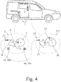
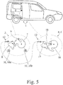
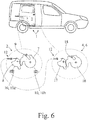
- the above-mentioned functional element 4 may also be a door arrester 6, which in Fig. 5 is shown as an example of a sliding door.
- a door lock 6 can be brought into an activation position and into a deactivation position.
- the door arrester 6 fixes upon reaching a fixing position of the motor vehicle door 3 (FIG. Fig. 5 ) the motor vehicle door 3, wherein the door lock 6 releases the motor vehicle door 3 in the deactivation position ( Fig. 6 ).
- Essential for the in Fig. 5 and Fig. 6 embodiment shown is that causes the motorized adjustment of at least one of the closing elements 7,8, here the pawl 8, the adjustment of the door arrester 6 in the activation position, so that after completion of the opening operation, a fixation of the vehicle door 3 in the fixing position possible is.
- the fixing position of the motor vehicle door 3 are here and preferably the in Fig. 5 shown open position.
- the motor vehicle lock 2 also has here the closing elements latch 7 and pawl 8, so that may be made to the extent to the comments on the first embodiment.
- the door lock 6 has a latch 16 and a pawl 17, wherein the latch 16 is again in a conventional manner with a closing part 18, here with a striker, in holding engagement can be brought.
- the opening of the motor vehicle door 3 begins at the in Fig. 4 to Fig. 6 illustrated embodiment with an opening operation explained above.
- the motorized lifting of the pawl 8 an adjustment of the door arrester 6, here the pawl 17 of the door arrester 6, adjusted to an activation position.
- the coupling of the pawl 8 of the motor vehicle lock 2 with the pawl 17 of the door arrester 6 is preferably provided in opposite directions, such that a lifting of the pawl 8 of the motor vehicle lock 2 causes the pawl 17 of the door arrester 6 and vice versa.
- the door lock 6 can be brought into its deactivation position only in that the pawl 8 of the motor vehicle lock 2 after the opening operation in the in Fig. 5 shown open position persists and for lifting the pawl 17 of the door arrester 6 by means of the drive assembly 10 in the direction of latch 7 is adjustable, so that the pawl 17 performs a corresponding counter-rotating movement and the latch 16 of the door arrester 6 releases.
- the functional element 4 is adjusted with the motorized adjustment of one of the closing elements 7,8.
- the basic idea of adjusting one of the closing elements 7, 8 to a separate functional element 4 with the motorized adjustment provides the conceptual basis for the above-described proposed motor vehicle lock arrangement 1. In that regard, reference may be made to the explanations there.
- the functional element 4 is adjusted with the motorized lifting of the pawl 8. Further preferably, it is provided here that the functional element 4 is an outside door handle 5, which is adjustable between a deactivation position and an engagement position, being adjusted in the context of the opening operation of the outside door handle 5 with the motorized lifting of the pawl 8 in the engaged position. Also in this respect may be made to the comments on the operation of the proposed door lock assembly 1.
Applications Claiming Priority (1)
| Application Number | Priority Date | Filing Date | Title |
|---|---|---|---|
| DE102016113155.5A DE102016113155A1 (de) | 2016-07-18 | 2016-07-18 | Kraftfahrzeugschlossanordnung |
Publications (2)
| Publication Number | Publication Date |
|---|---|
| EP3272977A1 true EP3272977A1 (fr) | 2018-01-24 |
| EP3272977B1 EP3272977B1 (fr) | 2024-01-17 |
Family
ID=59337567
Family Applications (1)
| Application Number | Title | Priority Date | Filing Date |
|---|---|---|---|
| EP17181226.6A Active EP3272977B1 (fr) | 2016-07-18 | 2017-07-13 | Systeme de serrure de véhicule automobile |
Country Status (2)
| Country | Link |
|---|---|
| EP (1) | EP3272977B1 (fr) |
| DE (1) | DE102016113155A1 (fr) |
Cited By (3)
| Publication number | Priority date | Publication date | Assignee | Title |
|---|---|---|---|---|
| WO2020098865A1 (fr) * | 2018-11-14 | 2020-05-22 | Kiekert Ag | Système de fermeture et/ou d'accès d'un véhicule automobile |
| WO2020234017A1 (fr) * | 2019-05-17 | 2020-11-26 | Brose Schliesssysteme Gmbh & Co. Kommanditgesellschaft | Ensemble serrure de véhicule automobile conçu pour une porte de véhicule automobile |
| WO2023110023A1 (fr) * | 2021-12-16 | 2023-06-22 | Kiekert Aktiengesellschaft | Ensemble porte de véhicule automobile |
Families Citing this family (2)
| Publication number | Priority date | Publication date | Assignee | Title |
|---|---|---|---|---|
| DE102019128289A1 (de) * | 2019-10-21 | 2021-04-22 | Kiekert Aktiengesellschaft | Kraftfahrzeugschloss, insbesondere Kraftfahrzeugtürschloss |
| DE102021118349A1 (de) | 2021-07-15 | 2023-01-19 | Brose Schließsysteme GmbH & Co. Kommanditgesellschaft | Kraftfahrzeugschloss |
Citations (7)
| Publication number | Priority date | Publication date | Assignee | Title |
|---|---|---|---|---|
| DE3939768A1 (de) * | 1989-12-01 | 1991-06-06 | Bayerische Motoren Werke Ag | Griff zum verschwenken eines klappbaren karosserieteils eines kraftfahrzeugs |
| DE19706952A1 (de) * | 1997-02-21 | 1998-08-27 | Mannesmann Vdo Ag | Schmutzfreier Öffnungsgriff für Heckklappen von Fahrzeugen |
| EP1384843A2 (fr) * | 2002-07-25 | 2004-01-28 | Huf Hülsbeck & Fürst GmbH & Co. KG | Dispositif d'ouverture ou de fermeture d'un capot, d'une porte ou similaire, notamment d'un hayon de véhicule |
| US20100270815A1 (en) * | 2009-04-28 | 2010-10-28 | Aisin Seiki Kabushiki Kaisha | Opening and closing member control device |
| US20110016794A1 (en) * | 2009-07-24 | 2011-01-27 | Aisin Seiki Kabushiki Kaisha | Apparatus for controlling opening-and-closing member for vehicle |
| US20110154740A1 (en) * | 2009-12-25 | 2011-06-30 | Aisin Seiki Kabushiki Kaisha | Door opening and closing apparatus for vehicle |
| WO2015185364A1 (fr) * | 2014-06-05 | 2015-12-10 | Huf Hülsbeck & Fürst Gmbh & Co. Kg | Système de serrure pour véhicule automobile |
Family Cites Families (6)
| Publication number | Priority date | Publication date | Assignee | Title |
|---|---|---|---|---|
| JP3502599B2 (ja) * | 2000-09-11 | 2004-03-02 | 三井金属鉱業株式会社 | 車両ドアラッチ装置 |
| JP4755528B2 (ja) * | 2006-05-17 | 2011-08-24 | 三井金属アクト株式会社 | 車両用ドアラッチのリモートコントロール装置 |
| US8894103B2 (en) * | 2012-06-29 | 2014-11-25 | Aisin Seiki Kabushiki Kaisha | Vehicle door opening-closing device |
| DE202013003241U1 (de) * | 2013-04-09 | 2014-07-11 | BROSE SCHLIEßSYSTEME GMBH & CO. KG | Fixiereinrichtung für eine Schiebetür eines Kraftfahrzeugs |
| DE102014205370A1 (de) * | 2014-03-22 | 2015-09-24 | BROSE SCHLIEßSYSTEME GMBH & CO. KG | Kraftfahrzeug-Schließsystem |
| DE102014205371A1 (de) | 2014-03-22 | 2015-09-24 | BROSE SCHLIEßSYSTEME GMBH & CO. KG | Kraftfahrzeugschlossanordnung |
-
2016
- 2016-07-18 DE DE102016113155.5A patent/DE102016113155A1/de not_active Withdrawn
-
2017
- 2017-07-13 EP EP17181226.6A patent/EP3272977B1/fr active Active
Patent Citations (7)
| Publication number | Priority date | Publication date | Assignee | Title |
|---|---|---|---|---|
| DE3939768A1 (de) * | 1989-12-01 | 1991-06-06 | Bayerische Motoren Werke Ag | Griff zum verschwenken eines klappbaren karosserieteils eines kraftfahrzeugs |
| DE19706952A1 (de) * | 1997-02-21 | 1998-08-27 | Mannesmann Vdo Ag | Schmutzfreier Öffnungsgriff für Heckklappen von Fahrzeugen |
| EP1384843A2 (fr) * | 2002-07-25 | 2004-01-28 | Huf Hülsbeck & Fürst GmbH & Co. KG | Dispositif d'ouverture ou de fermeture d'un capot, d'une porte ou similaire, notamment d'un hayon de véhicule |
| US20100270815A1 (en) * | 2009-04-28 | 2010-10-28 | Aisin Seiki Kabushiki Kaisha | Opening and closing member control device |
| US20110016794A1 (en) * | 2009-07-24 | 2011-01-27 | Aisin Seiki Kabushiki Kaisha | Apparatus for controlling opening-and-closing member for vehicle |
| US20110154740A1 (en) * | 2009-12-25 | 2011-06-30 | Aisin Seiki Kabushiki Kaisha | Door opening and closing apparatus for vehicle |
| WO2015185364A1 (fr) * | 2014-06-05 | 2015-12-10 | Huf Hülsbeck & Fürst Gmbh & Co. Kg | Système de serrure pour véhicule automobile |
Cited By (3)
| Publication number | Priority date | Publication date | Assignee | Title |
|---|---|---|---|---|
| WO2020098865A1 (fr) * | 2018-11-14 | 2020-05-22 | Kiekert Ag | Système de fermeture et/ou d'accès d'un véhicule automobile |
| WO2020234017A1 (fr) * | 2019-05-17 | 2020-11-26 | Brose Schliesssysteme Gmbh & Co. Kommanditgesellschaft | Ensemble serrure de véhicule automobile conçu pour une porte de véhicule automobile |
| WO2023110023A1 (fr) * | 2021-12-16 | 2023-06-22 | Kiekert Aktiengesellschaft | Ensemble porte de véhicule automobile |
Also Published As
| Publication number | Publication date |
|---|---|
| EP3272977B1 (fr) | 2024-01-17 |
| DE102016113155A1 (de) | 2018-01-18 |
Similar Documents
| Publication | Publication Date | Title |
|---|---|---|
| DE102012111397B4 (de) | Motorhaubenverriegelungsvorrichtung mit Zwei-Stufen-Führung für ein Fahrzeug | |
| EP3272977B1 (fr) | Systeme de serrure de véhicule automobile | |
| DE19642698C2 (de) | Türgriff für ein Kraftfahrzeug | |
| DE4343339C2 (de) | Kraftfahrzeugtürverschluß mit Kindersicherungseinrichtung | |
| DE102008063318A1 (de) | Türschließvorrichtung für Fahrzeuge | |
| DE4222868A1 (de) | Sperrvorrichtung für Türen eines Kraftfahrzeugs | |
| EP4077842B1 (fr) | Système de fermeture de porte de véhicule à moteur | |
| DE3908183A1 (de) | Kraftfahrzeug-tuerverschluss | |
| DE102015113222A1 (de) | Sicherheitsvorrichtung mit einer Fronthaube und einem Bajonettverschlusssystem | |
| DE102017106707A1 (de) | Kraftfahrzeugtürverschluss | |
| DE102011108438A1 (de) | Kraftfahrzeugschloss | |
| DE10320448A1 (de) | Kraftfahrzeugtürverschluss | |
| DE102009050077A1 (de) | Fahrzeugschloss | |
| EP3513021B1 (fr) | Serrure d'ouvrant de véhicule automobile | |
| DE102006058501A1 (de) | Scharnier zur gelenkigen Anbringung einer Klappe an einer Karosserie eines Kraftfahrzeugs | |
| DE10116224B4 (de) | Verfahren und Vorrichtung zur Verstellung einer türseitigen Sicherungseinrichtung einer Flugzeugtür | |
| DE102019113058A1 (de) | Kraftfahrzeugschlossanordnung für eine Kraftfahrzeugtür | |
| DE102012017515B4 (de) | Schließvorrichtung für eine verschiebbare Laderaumabdeckung, Laderaumabdeckung mit einer Schließvorrichtung und Fahrzeug mit einer derartigen Laderaumabdeckung | |
| DE10061641B4 (de) | Betätigungsvorrichtung für eine zwischen einer Öffnungs-und einer Schließlage schwenkbare Abdeckung, insbesondere eine Fahrzeug-Heckklappe | |
| DE102010053179A1 (de) | Kraftfahrzeugtürverschluss | |
| DE102019131351A1 (de) | Rückenlehnenverriegelungsvorrichtung und Rückenlehnenanordnung für ein Kraftfahrzeug | |
| DE202008001247U1 (de) | Kraftfahrzeug | |
| DE102005023224B4 (de) | Betätigungsvorrichtung für Fanghaken einer Fronthaube | |
| WO2019063755A1 (fr) | Serrure de véhicule automobile | |
| DE102019215279B4 (de) | Türschlosseinrichtung und Fahrzeugtür |
Legal Events
| Date | Code | Title | Description |
|---|---|---|---|
| PUAI | Public reference made under article 153(3) epc to a published international application that has entered the european phase |
Free format text: ORIGINAL CODE: 0009012 |
|
| STAA | Information on the status of an ep patent application or granted ep patent |
Free format text: STATUS: THE APPLICATION HAS BEEN PUBLISHED |
|
| AK | Designated contracting states |
Kind code of ref document: A1 Designated state(s): AL AT BE BG CH CY CZ DE DK EE ES FI FR GB GR HR HU IE IS IT LI LT LU LV MC MK MT NL NO PL PT RO RS SE SI SK SM TR |
|
| AX | Request for extension of the european patent |
Extension state: BA ME |
|
| STAA | Information on the status of an ep patent application or granted ep patent |
Free format text: STATUS: REQUEST FOR EXAMINATION WAS MADE |
|
| 17P | Request for examination filed |
Effective date: 20180724 |
|
| RBV | Designated contracting states (corrected) |
Designated state(s): AL AT BE BG CH CY CZ DE DK EE ES FI FR GB GR HR HU IE IS IT LI LT LU LV MC MK MT NL NO PL PT RO RS SE SI SK SM TR |
|
| STAA | Information on the status of an ep patent application or granted ep patent |
Free format text: STATUS: EXAMINATION IS IN PROGRESS |
|
| 17Q | First examination report despatched |
Effective date: 20180919 |
|
| STAA | Information on the status of an ep patent application or granted ep patent |
Free format text: STATUS: EXAMINATION IS IN PROGRESS |
|
| STAA | Information on the status of an ep patent application or granted ep patent |
Free format text: STATUS: EXAMINATION IS IN PROGRESS |
|
| GRAP | Despatch of communication of intention to grant a patent |
Free format text: ORIGINAL CODE: EPIDOSNIGR1 |
|
| STAA | Information on the status of an ep patent application or granted ep patent |
Free format text: STATUS: GRANT OF PATENT IS INTENDED |
|
| INTG | Intention to grant announced |
Effective date: 20230329 |
|
| GRAJ | Information related to disapproval of communication of intention to grant by the applicant or resumption of examination proceedings by the epo deleted |
Free format text: ORIGINAL CODE: EPIDOSDIGR1 |
|
| STAA | Information on the status of an ep patent application or granted ep patent |
Free format text: STATUS: EXAMINATION IS IN PROGRESS |
|
| INTC | Intention to grant announced (deleted) | ||
| GRAP | Despatch of communication of intention to grant a patent |
Free format text: ORIGINAL CODE: EPIDOSNIGR1 |
|
| STAA | Information on the status of an ep patent application or granted ep patent |
Free format text: STATUS: GRANT OF PATENT IS INTENDED |
|
| INTG | Intention to grant announced |
Effective date: 20230828 |
|
| GRAS | Grant fee paid |
Free format text: ORIGINAL CODE: EPIDOSNIGR3 |
|
| GRAA | (expected) grant |
Free format text: ORIGINAL CODE: 0009210 |
|
| STAA | Information on the status of an ep patent application or granted ep patent |
Free format text: STATUS: THE PATENT HAS BEEN GRANTED |
|
| AK | Designated contracting states |
Kind code of ref document: B1 Designated state(s): AL AT BE BG CH CY CZ DE DK EE ES FI FR GB GR HR HU IE IS IT LI LT LU LV MC MK MT NL NO PL PT RO RS SE SI SK SM TR |
|
| REG | Reference to a national code |
Ref country code: GB Ref legal event code: FG4D Free format text: NOT ENGLISH |
|
| REG | Reference to a national code |
Ref country code: DE Ref legal event code: R096 Ref document number: 502017015760 Country of ref document: DE |
|
| REG | Reference to a national code |
Ref country code: CH Ref legal event code: EP |
|
| REG | Reference to a national code |
Ref country code: IE Ref legal event code: FG4D Free format text: LANGUAGE OF EP DOCUMENT: GERMAN |