EP3269284B2 - Vorrichtung und verfahren zum unterstützen eines energiesparenden betriebs eines bodenpflegegeräts und bodenpflegegerät - Google Patents
Vorrichtung und verfahren zum unterstützen eines energiesparenden betriebs eines bodenpflegegeräts und bodenpflegegerät Download PDFInfo
- Publication number
- EP3269284B2 EP3269284B2 EP17178283.2A EP17178283A EP3269284B2 EP 3269284 B2 EP3269284 B2 EP 3269284B2 EP 17178283 A EP17178283 A EP 17178283A EP 3269284 B2 EP3269284 B2 EP 3269284B2
- Authority
- EP
- European Patent Office
- Prior art keywords
- floor care
- care appliance
- information
- floor
- light source
- Prior art date
- Legal status (The legal status is an assumption and is not a legal conclusion. Google has not performed a legal analysis and makes no representation as to the accuracy of the status listed.)
- Active
Links
Images


Classifications
-
- A—HUMAN NECESSITIES
- A47—FURNITURE; DOMESTIC ARTICLES OR APPLIANCES; COFFEE MILLS; SPICE MILLS; SUCTION CLEANERS IN GENERAL
- A47L—DOMESTIC WASHING OR CLEANING; SUCTION CLEANERS IN GENERAL
- A47L9/00—Details or accessories of suction cleaners, e.g. mechanical means for controlling the suction or for effecting pulsating action; Storing devices specially adapted to suction cleaners or parts thereof; Carrying-vehicles specially adapted for suction cleaners
- A47L9/28—Installation of the electric equipment, e.g. adaptation or attachment to the suction cleaner; Controlling suction cleaners by electric means
- A47L9/2805—Parameters or conditions being sensed
-
- A—HUMAN NECESSITIES
- A47—FURNITURE; DOMESTIC ARTICLES OR APPLIANCES; COFFEE MILLS; SPICE MILLS; SUCTION CLEANERS IN GENERAL
- A47L—DOMESTIC WASHING OR CLEANING; SUCTION CLEANERS IN GENERAL
- A47L9/00—Details or accessories of suction cleaners, e.g. mechanical means for controlling the suction or for effecting pulsating action; Storing devices specially adapted to suction cleaners or parts thereof; Carrying-vehicles specially adapted for suction cleaners
- A47L9/02—Nozzles
Definitions
- the invention relates to a device for supporting energy-saving operation of a floor care appliance, a method for supporting energy-saving operation of a floor care appliance and a floor care appliance.
- Modern household appliances are often equipped with a light display and/or rechargeable electrochemical energy stores such as e.g. B. so-called battery packs or battery modules.
- the EP 1 576 632 B1 describes a household appliance, in particular a built-in household appliance, with a visual operating indicator.
- the DE 10 2012 107689 B3 discloses a vacuum cleaner with a projection unit with which images of operating elements, display elements or other information of the vacuum cleaner can be displayed on a projection surface.
- a sensor device With a sensor device, the actuation of the projected operating and display elements by the user is recognized by gestures and used to control the vacuum cleaner.
- the disadvantage here is that the projection device does not project any information about the state of charge of an electrochemical store and is not suitable for supporting energy-saving operation of the vacuum cleaner.
- the U.S. 2008/178916 A1 discloses a dishwasher with a projection unit which projects status information about the cleaning operation of the dishwasher onto a projection surface.
- the disadvantage here is that the projection of the status information is only suitable for monitoring the dishwasher operation.
- the invention is based on the object of creating an improved device for supporting energy-saving operation of a floor care appliance, an improved floor care appliance and an improved method for supporting energy-saving operation of a floor care appliance.
- this object is achieved by a device for supporting energy-saving operation of a floor care device, by an improved floor care device and finally an improved method for supporting energy-saving operation of a floor care device with the features of the main claim.
- a device for a floor care device enables energy-saving operation of the floor care device by using a projection device that is designed to project information about a state of charge of an electrochemical store of the floor care device and a recommended operating state for the floor care device onto a surface located outside of the floor care device.
- the service life of the rechargeable battery device preferably a so-called vacuum cleaner designed as a rechargeable battery stick, or the electrochemical storage device of the floor care device can be advantageously extended and thus longer switch-on times of the floor care device can be achieved by reducing the power of the device, when not needed.
- a device for supporting energy-saving operation of a floor care device preferably a rechargeable battery stick, has the following feature: a projection device which is arranged on the floor care device and is designed to project information about a charge state of an electrochemical store of the floor care device and a recommended operating state for the floor care device onto a surface located outside of the floor care device.
- the floor care device can be an electrically operated mobile device for cleaning the floor in rooms, e.g. B. a canister vacuum cleaner act.
- the floor care device can be used instead of a cable for electrically connecting the floor care device to a socket or in addition to the cable with the energy storage device that can be used directly on the device, e.g. B a rechargeable battery, be equipped.
- the information about the state of charge of the electrochemical store or the recommended operating state can have characters and/or symbols projected onto the surface by the projection device.
- the state of charge of the electrochemical store can provide information about how much energy is currently still available for the proper operation of the floor care device through the electrochemical store.
- the projection device can be designed to project the information or an image of the information from an interior of the floor care appliance onto the surface located outside of the floor care appliance, e.g. B. a floor surface to be cleaned by the floor care device, and to make it visible and readable there for a user of the floor care device.
- the projection device can be designed to project the information onto a suction area of the floor care device that is located in front of a floor nozzle of the floor care device, as seen from a user of the floor care device.
- the information can thus advantageously be presented to the user in an unmissable manner in his direct field of vision, since the user's gaze usually rests on the suction area when using the floor care device.
- the device can have an interface for receiving a signal representing the state of charge and/or a load moment of the floor care appliance.
- the projection device can be designed to project the information using the signal.
- the signal can be an electrical signal provided by a sensor of the floor care device, for example.
- the information can be regularly updated according to the current device status.
- the projection device can have at least one pane and one light source.
- the light source can be arranged in an interior of the floor care appliance and designed to emit electromagnetic radiation in the range visible to humans.
- the pane can be arranged to cover the light source on at least one section of a housing of the floor care appliance.
- an information area of the pane opposite the light source can be formed in order to make the information visible when the electromagnetic radiation is emitted.
- the disk may be formed of a clear plastics material and form part of the body of a floor nozzle of the floor care implement.
- the light source can be z. B. be an LED, which is located inside the floor nozzle and is aimed at the pane.
- the information area of the disk can be partially structured by structuring the disk, e.g. B. an engraving representing the information may be formed.
- the projection device can be implemented with little outlay in terms of material and costs.
- the information area can have an optical lens.
- the information can advantageously be enlarged and thus projected onto the surface so that it is easier to read.
- the projection device can be designed to project the information onto the surface as text, which represents a recommendation for the user to switch the floor care device to a lower power level.
- the user can be supported in a simple and understandable way when using the device in an energy-saving manner.
- the projection device can be designed to project the information as a text representing the state of charge and/or a symbol representing the state of charge onto the surface. In this way, it can easily be prevented that the user is surprised by the complete emptying of the electrochemical store and has to interrupt the cleaning process prematurely.
- the projection device has at least one additional light source arranged in the interior of the floor care appliance for emitting additional electromagnetic radiation, and the pane arranged to cover the additional light source has an additional information area opposite the additional light source in order to, when emitting the additional electromagnetic radiation to make further information visible.
- different relevant information can advantageously be displayed to the user at the same time in the field of vision.
- the information can relate to a state of charge of the electrochemical store of the floor care appliance and the further information can represent a recommended operating state for the floor care appliance. In this way, all important information for energy-saving operation of the floor care device can be made accessible to the user at the same time.
- the projection device can have an additional light source arranged in the interior of the floor care appliance for emitting additional electromagnetic radiation, and the pane arranged to cover the additional light source can also have an additional information area opposite the additional light source, in order to make additional information visible when the additional electromagnetic radiation is emitted to make, in particular wherein the additional information can represent another recommended operating state for the floor care device.
- the operating time of the floor care device can advantageously be further extended.
- the projection device can also have a further additional light source arranged in the interior of the floor care appliance for emitting a further additional electromagnetic radiation.
- the further additional light source can be designed to illuminate the suction area of the floor care device.
- a floor care appliance has a device according to one of the embodiments explained above.
- the device is arranged on a floor nozzle of the floor care device.
- a method for supporting energy efficient operation of a floor care appliance comprises the following step: Projecting information about a state of charge of an electrochemical store of the floor care device and a recommended operating state for the floor care device onto a surface located outside of the floor care device using a projection device that is arranged on the floor care device.
- This method can be implemented, for example, in software or hardware or in a mixed form of software and hardware, for example in a device or a control device.
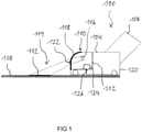
- figure 1 1 shows a floor care device 100 with a device 102 for supporting an energy-saving operation of the floor care device 100 according to an exemplary embodiment.
- the floor care device 100 is the in figure 1
- the exemplary embodiment shown is a floor vacuum cleaner 100, of which only a floor nozzle 104 and a connecting piece 106 connecting the floor nozzle 104 to a suction tube of the floor vacuum cleaner 100 are shown as representative and for the sake of clarity.
- a battery module equipped which is arranged directly on the device 100 and can be removed from the device 100 for charging. If required, the rechargeable battery module can be accommodated within the device housing or in or on the floor nozzle for operational use.
- the floor nozzle 104 is equipped with a plurality of rollers on the underside, by means of which the floor nozzle 104 is rolled over a surface 108 to be cleaned, here a floor 108, by a user of the floor care device 100 using a handle on the suction tube.
- the device 102 is at the in figure 1
- the exemplary embodiment shown is integrated into the floor nozzle 104 and includes a projection device 110, which is designed to project information 112 about a state of charge of the electrochemical store and/or a recommended operating state for the floor care device 100 onto a surface 114 located outside of the floor care device 100, here a surface 114 itself in the representation in figure 1 suction area 114 of the floor surface 108 located in front of the floor nozzle 104.
- the projection device 110 has at least one light source 116 and a pane 118 .
- the light source 116 is an LED 116 which is designed to emit white or colored light in the spectral range that is visible to humans.
- the LED 116 is arranged inside the floor nozzle 104 so that it is directed towards the pane 118 and, when activated, emits a light beam that is directed slightly downwards in the direction of the floor 108 .
- the disk 118 forms part of a housing 120 of the floor nozzle 104 and is transparent to the electromagnetic radiation emitted by the light source 116 .
- the disc 118 is integrated opposite the light source 116 in a front housing wall of the floor nozzle 104 in the thrust direction of the floor nozzle 104 and consists of figure 1 made of a transparent plastic material. Furthermore, at the in figure 1 In the exemplary embodiment shown, the disc 118 is curved and thus follows a shape of the floor nozzle housing 120 that is rounded at the top and front.
- the disc 118 can be formed in one piece with the rest of the housing 120 or can be designed as a separate element that is used when the floor nozzle 104 is installed in the housing 120 is inserted.
- the pane 118 has an information area 122 in a section in which the radiation from the light source 116 impinges on it.
- the information area 122 forms a structure representing the information 112, e.g. B. an engraving from. If radiation emitted by light source 116 passes through pane 118 at information area 122, information 112 is thrown in the form of a projection into an area defined by the inclination of light source 116 in suction area 114 and can be picked up there by the user handling floor care appliance 100 be recognized and read from its position behind the floor nozzle 104 and in view of the suction area 114.
- the user handling the floor care device 100 is informed about the current charge level of the device battery and/or an operating state that is currently more optimal than the set operating state for the floor care device 100.
- the user can then, for example by pressing suitable buttons, select the optimal operating state or mode. e.g. a lower power level - activate on device 100.
- disk 118 is embodied as a composite injection molded article consisting of one or more layers of foil and disk.
- the information area 122 has an optical lens or is in the form of an optical lens. In this way, the information 112 is enlarged and thus projected into the suction area 114 by the projection device 110 so that it is easier to read.
- the information to be projected can also be incorporated directly into the light source 116 and upon activation of the light source 116 through the transparent pane 118, the z. B. has a lens, are thrown into the suction area 114 .
- the light source 116 can be in the form of a laser which writes the information 112 through the transparent pane 118 into the suction area 114 by means of successive points of light.
- the device 102 has an interface 124 for receiving a signal 126 .
- the signal 126 represents, for example, the state of charge of the electrochemical store of the floor care device 100.
- the signal 126 can represent a current load torque of a brush element of the floor care device 100 rotating in the floor nozzle 104.
- the load moment gives an indication of what type of floor covering is currently being worked on by the floor nozzle 104 and whether a currently set power level of the floor care device 100 can possibly be reduced in order to extend the battery power with an undiminished cleaning power.
- two or more signals 126 can also be provided to the interface 124, one of which represents, for example, the battery charge state and another the load moment.
- the signals 126 are provided, for example, by sensors installed in the floor care device 100 and are read directly or after suitable data processing into the projection device 110 or a control unit for the projection device 110 in order to project the information 112 using the signal(s) 126.
- figure 1 clearly illustrates the approach proposed here for a new type of so-called eco-feedback using light on electric floor nozzles 104 for floor care devices 100.
- the device 100 determines more or less independently whether less power is sufficient for the surface to be cleaned at the moment, and reports this to the user using the in information 112 projected back into the suction area 114 .
- the customer or user also no longer needs to actively move from a working position to a viewing position in order to find out how much energy is still available to him in the battery and at which level he is operating his device 100 in the most energy-saving manner possible.
- figure 2 shows a perspective view of an embodiment of the floor care device 100 presented here with eco or info beam to support energy-saving operation of the floor care device 100.
- the design of the projection device 110 of the floor nozzle 104 corresponds to that in figure 1 shown, with the difference that several light sources or LEDs are used here.
- the projection device 110 comprises a further light source 200 for emitting further electromagnetic radiation and an additional light source 202 for emitting additional electromagnetic radiation.
- the light sources 116, 200, 202 are equally spaced from each other in a row im Arranged inside the floor nozzle 104 and directed at the plastic disc 118 with an identical angle of inclination.
- the plastic pane 118 extends over the entire width of the floor nozzle 104 and thus completely covers all three light sources 116, 200, 202.
- pane 118 has, in addition to the information area, a further information area which, when floor nozzle 104 is installed, is opposite the additional light source 200, and an additional information area on which, when installed, the Floor nozzle 104 of the additional light source 202 is opposite.
- the information areas represent different information, so that in interaction with the light sources 116, 200, 202 three different - in the illustration in figure 2 information is projected into the suction area in front of the floor nozzle 104 - symbolized by spaced-apart circles.
- the number of light sources 116, 200, 202 in the projection device 110 can be varied as desired, depending on the specification.
- additional LEDs can be installed for general illumination of the suction area, which are continuously switched on during operation of the floor care device 100, while the figure 2 LEDs 116, 200, 202 shown only light up if they receive a specific signal - such as e.g. B. the information about a low battery level - should be transmitted to the user.
- the pane 118 is then designed, as described, in such a way that it implements different light projections depending on the light source.
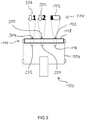
- figure 3 10 shows the exemplary floor nozzle 104 in a schematic plan view figure 2 viewed from above.
- the user's gaze is directed most of the time towards the suction area 114, which is located behind the floor nozzle 104 as seen from the user's point of view - in the illustration in figure 3 above the floor nozzle 104 - is located.
- the variant of the projection device 110 shown is designed such that the LED 116 in combination with the information area 122 in the pane 118 projects the information 112 as information about the current state of charge of the electrochemical store of the floor care appliance 100 into the suction area 114.
- the device for supporting energy-saving operation of a floor care appliance 100 which has the projection device 110, is designed in such a way that the information 112 is displayed, ie the LED 116 is activated or switched on, when the battery level is low.
- the in figure 3 shown embodiment becomes catchy The symbol of an almost empty battery is used to represent this circumstance, which is generally interpreted as an indication "recharge the battery".
- the further LED 200 in combination with a further information area 300 in the pane 118, displays further information 302, which consists of an arrow pointing downwards in the direction of view of the user and the number 2.
- further information 302 which consists of an arrow pointing downwards in the direction of view of the user and the number 2.
- the additional LED 202 When activated, the additional LED 202, in combination with an additional information area 304 in the pane 118, displays additional information 306, which in turn consists of an arrow pointing downwards in the direction of the user's gaze and the number 1.
- additional information 306 which in turn consists of an arrow pointing downwards in the direction of the user's gaze and the number 1.
- the information 122, 302, 306 can each be displayed individually or in various combinations. For example, information 112 and additional information 302 can be displayed together, or information 112 and additional information 306 can be displayed together.
- the information areas 122, 300, 304 are designed as optical lenses, so that the information 112, 302, 306 is projected enlarged into the viewing area 114.
- the floor nozzle 104 for the floor care device 100 is equipped with one or more electrically driven brush rollers for picking up particles from the surface to be cleaned. Different speeds of the brush rollers are achieved via different voltage levels of the device 100, which corresponds to the different power levels. By measuring the current from the roller drive, the type of floor covering can be detected. If there is a carpet, the brush roller engages deeply and experiences a high load moment. Accordingly, a high current is measured. If the floor is hard, the brush roller does not engage deeply and experiences a low load moment. In this case, the voltage could also be reduced, which means that a lower speed and also lower power can be set.
- the LEDs 116, 200, 202 in the floor nozzle 104 text fields in the form of the information 112, 302, 306 are projected in front of the floor nozzle 104 via the lens-like disk 118.
- the number of the power level to be selected and an arrow pointing down similar to today's displays in modern vehicles) or alternatively, for example, "Eco".
- the lettering or the LED 116, 200, 202 generating the lettering is automatically switched off after a certain time in order to avoid a disruptive effect on the user.
- a different lettering or symbol can be displayed, e.g. B. a socket symbol, analogous to the petrol pump symbol in the car, or an indication of an existing remaining charge such as "5%" or - as in figure 3 shown - the symbol 112 of the almost empty battery.
- This display is made by flashing another LED 116, 200, 202, because the pane 118 is designed due to the different information areas 122, 300, 304 in such a way that, depending on the respectively activated light source 116, 200, 202, different information 112, 302, 306 makes visible.
- FIG. 4 shows a flow chart of an embodiment of a method 400 for supporting an energy-saving operation of a floor care device.
- the method 400 can be used by the in figure 1 shown device for supporting energy-saving operation of a floor care device or a control device connected to the device.
- a receiving step 401 information about a state of charge of an electrochemical store of the floor care device and/or a recommended operating state for the floor care device is received via a suitable interface.
- a projection step 402 the information received in step 401 or the information received in step 401 is projected onto a surface located outside of the floor care appliance using a projection device which is arranged on the floor care appliance.
- a feature can be integrated into the floor nozzle 104 of floor care devices through a one-time effort in the software and tool costs, which causes only low material and assembly costs, especially if the floor nozzle 104 is already equipped with LED illumination .
- the service life of battery-powered floor care devices such as e.g. B. vacuum cleaners effectively while giving the customer better control over the energy management of the device.
Landscapes
- Engineering & Computer Science (AREA)
- Mechanical Engineering (AREA)
- Projection Apparatus (AREA)
- Electric Vacuum Cleaner (AREA)
Description
- Die Erfindung betrifft eine Vorrichtung zum Unterstützen eines energiesparenden Betriebs eines Bodenpflegegeräts, weiterhin ein Verfahren zum Unterstützen eines energiesparenden Betriebs eines Bodenpflegegeräts sowie ein Bodenpflegegerät.
- Moderne Haushaltgeräte sind für eine komfortable Bedienung häufig mit einer Lichtanzeige und/oder wiederaufladbaren elektrochemischen Energiespeichern wie z. B. sogenannten Akkublocks oder Akkumodulen ausgestattet.
- Die
EP 1 576 632 B1 beschreibt ein Haushaltgerät, insbesondere ein Einbau-Haushaltgerät, mit einer optischen Betriebsanzeige. - Die
DE 10 2012 107689 B3 offenbart einen Staubsauger mit einer Projektionseinheit mit der Bilder von Bedienelementen, Anzeigeelementen oder andere Informationen des Staubsaugers auf einer Projektionsfläche dargestellt werden können. Mit einer Sensoreinrichtung wird die Betätigung der projizierten Bedien- und Anzeigeelemente mittels Gesten durch den Benutzer erkannt und zur Steuerung des Staubsaugers verwendet. Nachteilig hierbei ist, dass die Projektionseinrichtung keine Informationen über den Ladungszustand eines elektrochemischen Speichers projiziert und nicht zur Unterstützung eines energiesparenden Betriebs des Staubsaugers geeignet ist. - Die
US 2008 / 178916 A1 offenbart eine Geschirrspülmaschine mit Projektionseinheit, welche eine Statusinformation des Reinigungsbetriebs der Geschirrspülmaschine auf eine Projektionsfläche projiziert. Nachteilig hierbei ist, dass sich die Projektion der Statusinformation nur zur Überwachung des Geschirrspülmaschinenbetriebs eignet. - Der Erfindung liegt die Aufgabe zugrunde, eine verbesserte Vorrichtung zum Unterstützen eines energiesparenden Betriebs eines Bodenpflegegeräts, ein verbessertes Bodenpflegegerät sowie ein verbessertes Verfahren zum Unterstützen eines energiesparenden Betriebs eines Bodenpflegegeräts zu schaffen.
- Erfindungsgemäß wird diese Aufgabe durch eine Vorrichtung zum Unterstützen eines energiesparenden Betriebs eines Bodenpflegegeräts, durch ein verbessertes Bodenpflegegerät sowie schließlich ein verbessertes Verfahren zum Unterstützen eines energiesparenden Betriebs eines Bodenpflegegeräts mit den Merkmalen des Hauptanspruchs gelöst. Vorteilhafte Ausgestaltungen und Weiterbildungen der Erfindung ergeben sich aus den nachfolgenden Unteransprüchen.
- Eine Vorrichtung für ein Bodenpflegegerät ermöglicht einen energiesparenden Betrieb des Bodenpflegegeräts durch einen Einsatz einer Projektionseinrichtung, die ausgebildet ist, um eine Information über einen Ladungszustand eines elektrochemischen Speichers des Bodenpflegegeräts und einen empfohlenen Betriebszustand für das Bodenpflegegerät auf eine außerhalb des Bodenpflegegeräts befindliche Fläche zu projizieren.
- Gemäß diesem hier vorgestellten Konzept können unter Einsatz lediglich geringer Material- und Montagekosten einem Nutzer des Bodenpflegegeräts auf einfache und gut sichtbare Weise Informationen über einen Betrieb des Bodenpflegegeräts in optimalen Leistungsstufen vermittelt werden. Durch ein gemäß dem vorgestellten Ansatz einfach umsetzbares optimales Energiemanagement können die Einsatzdauer des Akkugeräts, bevorzugt eines sogenannten als Akkustick ausgeführten Staubsaugers, bzw. elektrochemischen Speichers des Bodenpflegegeräts vorteilhaft verlängert und somit längere Einschaltzeiten des Bodenpflegegeräts erreicht werden, indem die Leistung des Geräts reduziert werden kann, wenn sie nicht benötigt wird.
- Eine Vorrichtung zum Unterstützen eines energiesparenden Betriebs eines Bodenpflegegeräts, vorzugsweise eines Akkusticks, weist das folgende Merkmal auf:
eine Projektionseinrichtung, die an dem Bodenpflegegerät angeordnet ist und ausgebildet ist, um eine Information über einen Ladungszustand eines elektrochemischen Speichers des Bodenpflegegeräts und einen empfohlenen Betriebszustand für das Bodenpflegegerät auf eine außerhalb des Bodenpflegegeräts befindliche Fläche zu projizieren. - Bei dem Bodenpflegegerät kann es sich um ein elektrisch betriebenes mobiles Gerät zum Reinigen des Bodens in Räumen, z. B. um einen Bodenstaubsauger, handeln. Für eine Verbesserung von Handhabungskomfort und Mobilität kann das Bodenpflegegerät anstelle eines Kabels zum elektrischen Verbinden des Bodenpflegegeräts mit einer Steckdose oder zusätzlich zu dem Kabel mit dem direkt am Gerät einsetzbaren Energiespeicher, z. B einer wiederaufladbaren Batterie, ausgestattet sein. Die Information über den Ladungszustand des elektrochemischen Speichers bzw. den empfohlenen Betriebszustand kann von der Projektionseinrichtung auf die Fläche projizierte Schriftzeichen und/oder Symbole aufweisen. Der Ladungszustand des elektrochemischen Speichers kann Auskunft darüber geben, wie viel Energie für den ordnungsgemäßen Betrieb des Bodenpflegegeräts durch den elektrochemischen Speicher aktuell noch zur Verfügung steht. Unter dem empfohlenen Betriebszustand kann eine vom Nutzer am Gerät einstellbare und in Bezug auf den aktuell behandelten Bodenbelag optimale Leistungsstufe des Bodenpflegegeräts verstanden werden. Die Projektionseinrichtung kann ausgebildet sein, um die Information bzw. ein Abbild der Information von einem Inneren des Bodenpflegegeräts auf die außerhalb des Bodenpflegegeräts befindliche Fläche, z. B. eine von dem Bodenpflegegerät zu reinigende Bodenfläche, optisch zu übertragen und dort für einen Nutzer des Bodenpflegegeräts sichtbar und lesbar zu machen.
- Gemäß einer Ausführungsform kann die Projektionseinrichtung ausgebildet sein, um die Information auf einen von einem Nutzer des Bodenpflegegeräts aus betrachtet vor einer Bodendüse des Bodenpflegegeräts gelegenen Saugbereich des Bodenpflegegeräts zu projizieren. Damit kann die Information dem Nutzer vorteilhaft unübersehbar in seinem direkten Sichtfeld präsentiert werden, da beim Einsatz des Bodenpflegegeräts der Blick des Nutzers in der Regel auf dem Saugbereich ruht.
- Gemäß einer weiteren Ausführungsform kann die Vorrichtung eine Schnittstelle zum Empfangen eines den Ladungszustand und/oder ein Lastmoment des Bodenpflegegeräts repräsentierenden Signals aufweisen. Dabei kann die Projektionseinrichtung ausgebildet sein, um die Information unter Verwendung des Signals zu projizieren. Bei dem Signal kann es sich um ein beispielsweise von einem Sensor des Bodenpflegegeräts bereitgestelltes elektrisches Signal handeln. Mit dieser Ausführungsform kann die Information regelmäßig entsprechend dem aktuellen Gerätezustand aktualisiert werden.
- Gemäß einer bevorzugten Ausführungsform kann die Projektionseinrichtung zumindest eine Scheibe und eine Lichtquelle aufweisen. Die Lichtquelle kann in einem Inneren des Bodenpflegegeräts angeordnet sein und ausgebildet sein, um eine elektromagnetische Strahlung im für den Menschen sichtbaren Bereich zu emittieren. Die Scheibe kann an zumindest einem Abschnitt eines Gehäuses des Bodenpflegegeräts die Lichtquelle abdeckend angeordnet sein. Dabei kann ein der Lichtquelle gegenüberliegender Informationsbereich der Scheibe ausgebildet sein, um bei dem Emittieren der elektromagnetischen Strahlung die Information sichtbar zu machen. Die Scheibe kann aus einem durchsichtigen Kunststoffmaterial gebildet sein und einen Teil des Gehäuses einer Bodendüse des Bodenpflegegeräts bilden. Bei der Lichtquelle kann es sich z. B. um eine LED handeln, die sich im Inneren der Bodendüse befindet und auf die Scheibe gerichtet ist. Der Informationsbereich der Scheibe kann durch eine partielle Strukturierung der Scheibe, z. B. eine die Information darstellende Gravur, gebildet sein. In dieser Ausführungsform kann die Projektionseinrichtung mit wenig Material- und Kostenaufwand realisiert werden.
- Beispielsweise kann der Informationsbereich eine optische Linse aufweisen. In dieser Variante der Projektionseinrichtung kann die Information vorteilhaft vergrößert und damit besser lesbar auf die Fläche projiziert werden.
- Gemäß einer besonderen Ausführungsform kann die Projektionseinrichtung ausgebildet sein, um die Information als einen Text auf die Fläche zu projizieren, der eine Empfehlung für den Nutzer, das Bodenpflegegerät in eine niedrigere Leistungsstufe zu schalten, repräsentiert. So kann der Nutzer auf einfache und verständliche Weise beim energiesparenden Einsatz des Geräts unterstützt werden.
- Ferner kann die Projektionseinrichtung ausgebildet sein, um die Information als einen den Ladungszustand repräsentierenden Text und/oder ein den Ladungszustand repräsentierendes Symbol auf die Fläche zu projizieren. Damit kann ohne Weiteres verhindert werden, dass der Nutzer von der vollständigen Entleerung des elektrochemischen Speichers überrascht wird und den Reinigungsprozess vorzeitig abbrechen muss.
- Günstig ist es auch, wenn die Projektionseinrichtung zumindest eine weitere in dem Inneren des Bodenpflegegeräts angeordnete Lichtquelle zum Emittieren einer weiteren elektromagnetischen Strahlung aufweist und die ferner die weitere Lichtquelle abdeckend angeordnete Scheibe einen der weiteren Lichtquelle gegenüberliegenden weiteren Informationsbereich aufweist, um bei dem Emittieren der weiteren elektromagnetischen Strahlung eine weitere Information sichtbar zu machen. Gemäß dieser Ausführungsform können dem Nutzer vorteilhaft unterschiedliche relevante Informationen gleichzeitig im Sichtbereich angezeigt werden.
- Beispielsweise kann die Information einen Ladungszustand des elektrochemischen Speichers des Bodenpflegegeräts betreffen und die weitere Information einen empfohlenen Betriebszustand für das Bodenpflegegerät repräsentieren. Damit können dem Nutzer alle wichtigen Informationen für einen energiesparenden Betrieb des Bodenpflegegeräts gleichzeitig zugänglich gemacht werden.
- Ferner kann die Projektionseinrichtung eine zusätzliche in dem Inneren des Bodenpflegegeräts angeordnete Lichtquelle zum Emittieren einer zusätzlichen elektromagnetischen Strahlung aufweisen und die ferner die zusätzliche Lichtquelle abdeckend angeordnete Scheibe einen der zusätzlichen Lichtquelle gegenüberliegenden zusätzlichen Informationsbereich aufweisen, um bei dem Emittieren der zusätzlichen elektromagnetischen Strahlung eine zusätzliche Information sichtbar zu machen, insbesondere wobei die zusätzliche Information einen weiteren empfohlenen Betriebszustand für das Bodenpflegegerät repräsentieren kann. Auf diese Weise kann die Betriebszeit des Bodenpflegegeräts vorteilhaft noch weitergehend verlängert werden.
- Auch kann die Projektionseinrichtung eine weitere zusätzliche in dem Inneren des Bodenpflegegeräts angeordnete Lichtquelle zum Emittieren einer weiteren zusätzlichen elektromagnetischen Strahlung aufweisen. Die weitere zusätzliche Lichtquelle kann ausgebildet sein, um den Saugbereich des Bodenpflegegeräts zu beleuchten. Mit dieser Ausführungsform kann dem Nutzer des Bodenpflegegeräts die Arbeit durch bessere Sichtbarkeit der Saugfläche vorteilhaft erleichtert werden.
- Ein Bodenpflegegerät weist eine Vorrichtung gemäß einer der im Vorangegangenen ausgeführten Ausführungsformen auf. Insbesondere ist die Vorrichtung an einer Bodendüse des Bodenpflegegeräts angeordnet.
- Ein Verfahren zum Unterstützen eines energiesparenden Betriebs eines Bodenpflegegeräts weist den folgenden Schritt auf:
Projizieren einer Information über einen Ladungszustand eines elektrochemischen Speichers des Bodenpflegegeräts und einen empfohlenen Betriebszustand für das Bodenpflegegerät auf eine außerhalb des Bodenpflegegeräts befindliche Fläche unter Verwendung einer Projektionseinrichtung, die an dem Bodenpflegegerät angeordnet ist. - Dieses Verfahren kann beispielsweise in Software oder Hardware oder in einer Mischform aus Software und Hardware, beispielsweise in einer Vorrichtung oder einem Steuergerät, implementiert sein.
- Auch durch diese Ausführungsvariante der Erfindung in Form eines Verfahrens kann die der Erfindung zugrunde liegende Aufgabe schnell und effizient gelöst werden.
- Ausführungsbeispiele der Erfindung sind in den Zeichnungen rein schematisch dargestellt und werden nachfolgend näher beschrieben. Es zeigt
- Figur 1
- eine schematische Darstellung eines Bodenpflegegeräts mit einer Vorrichtung zum Unterstützen eines energiesparenden Betriebs des Bodenpflegegeräts gemäß einem Ausführungsbeispiel;
- Figur 2
- eine perspektivische Darstellung eines Bodenpflegegeräts mit einer Vorrichtung zum Unterstützen eines energiesparenden Betriebs des Bodenpflegegeräts mit mehreren Lichtquellen gemäß einem Ausführungsbeispiel;
- Figur 3
- eine schematische Draufsicht auf ein Bodenpflegegerät mit einer Vorrichtung zum Unterstützen eines energiesparenden Betriebs des Bodenpflegegeräts mit Informationen zu Ladungs- und Betriebszustand gemäß einem Ausführungsbeispiel; und
- Figur 4
- ein Ablaufdiagramm eines Verfahrens zum Unterstützen eines energiesparenden Betriebs eines Bodenpflegegeräts gemäß einem Ausführungsbeispiel.
-
Figur 1 zeigt anhand einer schematischen Darstellung ein Bodenpflegegerät 100 mit einer Vorrichtung 102 zum Unterstützen eines energiesparenden Betriebs des Bodenpflegegeräts 100 gemäß einem Ausführungsbeispiel. Bei dem Bodenpflegegerät 100 handelt es sich bei dem inFigur 1 gezeigten Ausführungsbeispiel um einen Bodenstaubsauger 100, von dem stellvertretend und der Übersichtlichkeit halber lediglich eine Bodendüse 104 und ein die Bodendüse 104 mit einem Saugrohr des Bodenstaubsaugers 100 verbindender Anschlussstutzen 106 dargestellt ist. Die inFigur 1 gezeigte Variante des Bodenpflegegeräts 100 ist mit einem in den Figuren nicht gezeigten elektrochemischen Speicher, z. B. einem Akkumodul, ausgestattet, der direkt am Gerät 100 angeordnet ist und zum Aufladen vom Gerät 100 entfernt werden kann. Bedarfsweise kann das Akkumodul für den betriebsgemäßen Gebrauch innerhalb des Gerätehgehäuses oder in oder an der Bodendüse untergebracht sein. - Die Bodendüse 104 ist an der Unterseite mit einer Mehrzahl von Rollen ausgestattet, mittels denen die Bodendüse 104 über einen Handgriff am Saugrohr von einem Nutzer des Bodenpflegegeräts 100 über eine zu reinigende Fläche 108, hier einen Fußboden 108, gerollt wird. Die Vorrichtung 102 ist bei dem in
Figur 1 gezeigten Ausführungsbeispiel in die Bodendüse 104 integriert und umfasst eine Projektionseinrichtung 110, die ausgebildet ist, um eine Information 112 über einen Ladungszustand des elektrochemischen Speichers und/oder einen empfohlenen Betriebszustand für das Bodenpflegegerät 100 auf eine außerhalb des Bodenpflegegeräts 100 befindliche Fläche 114, hier einen sich in der Darstellung inFigur 1 vor der Bodendüse 104 befindlichen Saugbereich 114 der Fußbodenfläche 108, zu projizieren. - Bei dem in
Figur 1 gezeigten Ausführungsbeispiel weist die Projektionseinrichtung 110 mindestens eine Lichtquelle 116 und eine Scheibe 118 auf. Bei der Lichtquelle 116 handelt es sich hier um eine LED 116, die ausgebildet ist, um weißes oder farbiges Licht im für den Menschen sichtbaren Spektralbereich zu emittieren. Die LED 116 ist im Inneren der Bodendüse 104 auf die Scheibe 118 gerichtet angeordnet und emittiert im aktivierten Zustand einen leicht nach unten in Richtung des Fußbodens 108 gerichteten Lichtstrahl. - Die Scheibe 118 bildet einen Teil eines Gehäuses 120 der Bodendüse 104 und ist für die von der Lichtquelle 116 emittierte elektromagnetische Strahlung durchlässig. Die Scheibe 118 ist der Lichtquelle 116 gegenüberliegend in eine in Schubrichtung der Bodendüse 104 vordere Gehäusewand der Bodendüse 104 integriert und besteht in
Figur 1 aus einem transparenten Kunststoffmaterial. Ferner ist bei dem inFigur 1 gezeigten Ausführungsbeispiel die Scheibe 118 gebogen ausgeführt und folgt damit einer oben und vorne abgerundeten Form des Bodendüsengehäuses 120. Je nach Ausführung kann die Scheibe 118 einstückig mit dem restlichen Gehäuse 120 gebildet sein oder als separates Element ausgeführt sein, das bei der Montage der Bodendüse 104 in das Gehäuse 120 eingesetzt wird. - Die Scheibe 118 weist in einem Abschnitt, in dem die Strahlung der Lichtquelle 116 auf sie auftrifft, einen Informationsbereich 122 auf. Der Informationsbereich 122 bildet eine die Information 112 repräsentierende Struktur, z. B. eine Gravur, aus. Tritt nun von der Lichtquelle 116 emittierte Strahlung an dem Informationsbereich 122 durch die Scheibe 118 hindurch, wird die Information 112 in Form einer Projektion in einen durch die Neigung der Lichtquelle 116 definierten Bereich im Saugbereich 114 geworfen und kann dort von dem das Bodenpflegegerät 100 handhabenden Nutzer von seiner Position hinter der Bodendüse 104 und mit Blick auf den Saugbereich 114 erkannt und gelesen werden. Mithilfe der Information 112 erhält der das Bodenpflegegerät 100 handhabende Anwender Kenntnis über einen aktuellen Ladungsstand des Geräteakkus und/oder einen aktuell optimaleren als den eingestellten Betriebszustand für das Bodenpflegegerät 100. Der Nutzer kann dann beispielsweise durch Drücken geeigneter Knöpfe den optimalen Betriebszustand bzw. -modus - z. B. eine niedrigere Leistungsstufe - am Gerät 100 aktivieren.
- Gemäß einem Ausführungsbeispiel ist die Scheibe 118 als ein Verbundspritzgussartikel, bestehend aus einer oder mehreren Folien- und Scheibenlagen ausgeführt.
- Gemäß einem weiteren Ausführungsbeispiel weist der Informationsbereich 122 eine optische Linse auf bzw. ist in Form einer optischen Linse ausgebildet. So wird die Information 112 vergrößert und damit besser lesbar durch die Projektionseinrichtung 110 in den Saugbereich 114 projiziert.
- Alternativ zu dem in
Figur 1 gezeigten Ausführungsbeispiel kann die zu projizierende Information auch direkt in die Lichtquelle 116 eingearbeitet sein und bei Aktivierung der Lichtquelle 116 durch die durchsichtige Scheibe 118, die z. B. eine Linse aufweist, in den Saugbereich 114 geworfen werden. - Gemäß einem weiteren alternativen Ausführungsbeispiel kann die Lichtquelle 116 als ein Laser ausgebildet sein, der die Information 112 mittels aufeinanderfolgender Lichtpunkte durch die durchsichtige Scheibe 118 hindurch in den Saugbereich 114 schreibt.
- Bei der in
Figur 1 gezeigten Variante des Bodenpflegegeräts 100 weist die Vorrichtung 102 eine Schnittstelle 124 zum Empfangen eines Signals 126 auf. Das Signal 126 repräsentiert beispielsweise den Ladungszustand des elektrochemischen Speichers des Bodenpflegegeräts 100. Alternativ kann das Signal 126 ein aktuelles Lastmoment eines in der Bodendüse 104 rotierenden Bürstenelements des Bodenpflegegeräts 100 repräsentieren. Das Lastmoment gibt einen Hinweis darauf, welche Art Bodenbelag aktuell von der Bodendüse 104 bearbeitet wird, und ob eine aktuell eingestellte Leistungsstärke des Bodenpflegegeräts 100 eventuell reduziert werden kann, um bei unverminderter Reinigungskraft die Akkuleistung zu verlängern. - Es können selbstverständlich auch zwei oder mehr Signale 126 an die Schnittstelle 124 bereitgestellt werden, von denen beispielsweise eines den Akku-Ladungszustand und ein anderes das Lastmoment repräsentiert. Die Signale 126 werden beispielsweise von im Bodenpflegegerät 100 verbauten Sensoren bereitgestellt und direkt oder nach einer geeigneten Datenverarbeitung in die Projektionseinrichtung 110 oder ein Steuergerät für die Projektionseinrichtung 110 eingelesen, um die Information 112 unter Verwendung des bzw. der Signale 126 zu projizieren.
-
Figur 1 illustriert anschaulich den hierin vorgeschlagenen Ansatz für ein neuartiges sogenanntes Eco-Feedback mittels Licht an elektrischen Bodendüsen 104 für Bodenpflegegeräte 100. Das Gerät 100 stellt quasi selbstständig fest, ob für den momentan zu reinigenden Untergrund weniger Leistung ausreicht, und meldet dies dem Nutzer mittels der in den Saugbereich 114 projizierten Information 112 zurück. Der Kunde bzw. Nutzer braucht sich auch nicht mehr aktiv aus einer Arbeitsposition in eine Blickposition zu begeben, um herausfinden, wie viel Energie ihm im Akku noch zur Verfügung steht und auf welcher Stufe er sein Gerät 100 möglichst energiesparend betreibt. -
Figur 2 zeigt anhand einer perspektivischen Darstellung eine Ausführungsvariante des hierin vorgestellten Bodenpflegegeräts 100 mit Eco- bzw. Info-Beam zur Unterstützung eines energiesparenden Betriebs des Bodenpflegegeräts 100. Wieder ist stellvertretend für das Bodenpflegegerät 100 die Bodendüse 104 mit Anschlussstutzen dargestellt. Die Ausführung der Projektionseinrichtung 110 der Bodendüse 104 entspricht der inFigur 1 gezeigten, mit dem Unterschied, dass hier mehrere Lichtquellen bzw. LEDs zum Einsatz kommen. - Die Projektionseinrichtung 110 umfasst neben der Lichtquelle 116 eine weitere Lichtquelle 200 zum Emittieren einer weiteren elektromagnetischen Strahlung und eine zusätzliche Lichtquelle 202 zum Emittieren einer zusätzlichen elektromagnetischen Strahlung. Die Lichtquellen 116, 200, 202 sind gleichmäßig voneinander beabstandet in einer Reihe im Inneren der Bodendüse 104 angeordnet und mit identischem Neigungswinkel auf die Kunststoffscheibe 118 gerichtet. Die Kunststoffscheibe 118 erstreckt sich über eine gesamte Breite der Bodendüse 104 und deckt damit alle drei Lichtquellen 116, 200, 202 vollständig ab. In Übereinstimmung mit der Anzahl der Lichtquellen 116, 200, 202 weist die Scheibe 118 neben dem Informationsbereich einen weiteren Informationsbereich auf, der im montierten Zustand der Bodendüse 104 der weiteren Lichtquelle 200 gegenüber liegt, und einen zusätzlichen Informationsbereich auf, auf der im montierten Zustand der Bodendüse 104 der zusätzlichen Lichtquelle 202 gegenüber liegt.
- Bei dem in
Figur 2 gezeigten Ausführungsbeispiel der Projektionseinrichtung 110 repräsentieren die Informationsbereiche unterschiedliche Informationen, sodass im Zusammenspiel mit den Lichtquellen 116, 200, 202 drei unterschiedliche - in der Darstellung inFigur 2 durch voneinander beabstandete Kreise symbolisierte - Informationen in den Saugbereich vor der Bodendüse 104 projiziert werden. - Gemäß einem Ausführungsbeispiel kann die Anzahl der Lichtquellen 116, 200, 202 in der Projektionseinrichtung 110 je nach Spezifikation beliebig variiert werden. Beispielsweise können zusätzlich LEDs zur generellen Ausleuchtung des Saugbereiches verbaut sein, die während des Betriebs des Bodenpflegegeräts 100 kontinuierlich eingeschaltet sind, während die in
Figur 2 gezeigten LEDs 116, 200, 202 nur aufleuchten, falls sie ein bestimmtes Signal - wie z. B. die Information über einen niedrigen Akkustand - an den Anwender übertragen sollen. Für Letzteres ist die Scheibe 118 dann wie beschrieben so ausgeführt, dass sie abhängig von der Lichtquelle unterschiedliche Lichtprojektionen umsetzt. -
Figur 3 zeigt in einer schematischen Draufsicht die beispielhafte Bodendüse 104 ausFigur 2 von oben betrachtet. Im Einsatz des Bodenpflegegeräts 100 ist der Blick des Anwenders die meiste Zeit auf den Saugbereich 114 gerichtet, der sich vom Anwender aus betrachtet hinter der Bodendüse 104 - in der Darstellung inFigur 3 oberhalb der Bodendüse 104 - befindet. - Die in
Figur 3 gezeigte Variante der Projektionseinrichtung 110 ist so ausgeführt, dass die LED 116 in Kombination mit dem Informationsbereich 122 in der Scheibe 118 die Information 112 als eine Information über den aktuellen Ladungszustand des elektrochemischen Speichers des Bodenpflegegeräts 100 in den Saugbereich 114 projiziert. Die die Projektionseinrichtung 110 aufweisende Vorrichtung zum Unterstützen eines energiesparenden Betriebs eines Bodenpflegegeräts 100 ist dabei so ausgeführt, dass die Information 112 angezeigt wird, also die LED 116 aktiviert bzw. eingeschaltet wird, wenn der Akkustand niedrig ist. Bei dem inFigur 3 gezeigten Ausführungsbeispiel wird zur eingängigen Darstellung dieses Umstandes das Symbol einer fast leeren Batterie verwendet, das allgemeingültig als ein Hinweis "Akku aufladen" interpretiert wird. - Die weitere LED 200 zeigt im aktivierten Zustand in Kombination mit einem weiteren Informationsbereich 300 in der Scheibe 118 eine weitere Information 302 an, die aus einem in der Blickrichtung des Anwenders nach unten gerichteten Pfeil und der Zahl 2 besteht. Diese beiden Elemente bilden gemäß dem in
Figur 3 gezeigten Ausführungsbeispiel einen Inhalt der weiteren Information 302, der vom informierten oder intuitiven Nutzer als ein Hinweis für einen empfohlenen Betriebszustand, hier konkret als ein Hinweis "In Leistungsstufe 2 herunterschalten" interpretiert wird. - Die zusätzliche LED 202 zeigt im aktivierten Zustand in Kombination mit einem zusätzlichen Informationsbereich 304 in der Scheibe 118 eine zusätzliche Information 306 an, die wiederum aus einem in der Blickrichtung des Anwenders nach unten gerichteten Pfeil und der Zahl 1 besteht. Diese beiden Elemente bilden gemäß dem in
Figur 3 gezeigten Ausführungsbeispiel einen Inhalt der zusätzlichen Information 306, der vom informierten oder intuitiven Nutzer als Hinweis für einen weiteren empfohlenen Betriebszustand, hier konkret als ein Hinweis "In Leistungsstufe 1 herunterschalten" interpretiert wird. - Die Informationen 122, 302, 306 können je einzeln oder in verschiedenen Kombinationen angezeigt werden. Beispielsweise können die Information 112 und die weitere Information 302 gemeinsam angezeigt werden oder die Information 112 und die zusätzliche Information 306 gemeinsam angezeigt werden.
- Bei dem in
Figur 3 gezeigten Ausführungsbeispiel sind die Informationsbereiche 122, 300, 304 als optische Linsen ausgebildet, sodass die Informationen 112, 302, 306 vergrößert in den Sichtbereich 114 projiziert werden. - Die Bodendüse 104 für das Bodenpflegegerät 100 ist mit einer oder mehreren elektrisch angetriebenen Borstwalzen zum Aufnehmen von Partikeln vom zu reinigenden Untergrund ausgestattet. Über verschiedene Spannungsstufen des Geräts 100 werden unterschiedliche Drehzahlen der Borstwalzen erreicht, was den verschiedenen Leistungsstufen entspricht. Durch die Messung der Stromstärke vom Antrieb der Walze kann die Art des Bodenbelags detektiert werden. Liegt ein Teppich vor, greift die Borstwalze tief ein und erfährt ein hohes Lastmoment. Entsprechend wird eine hohe Stromstärke gemessen. Liegt ein Hartboden vor, greift die Borstwalze nicht tief ein und erfährt ein geringes Lastmoment. In diesem Fall könnte die Spannung auch herabgesetzt werden, wodurch eine geringere Drehzahl und auch geringere Leistung eingestellt werden kann.
- Nun werden wie beschrieben mit den LEDs 116, 200, 202 in der Bodendüse 104 über die linsenartige Scheibe 118 Schriftfelder in Form der Informationen 112, 302, 306 vor die Bodendüse 104 projiziert. Beispielsweise wie in
Figur 3 gezeigt die Zahl der zu wählenden Leistungsstufe und ein Pfeil nach unten (ähnlich zu heutigen Anzeigen in modernen Fahrzeugen) oder alternativ beispielsweise ein Schriftzug "Eco". Gemäß einem bevorzugten Ausführungsbeispiel wird der Schriftzug bzw. die den Schriftzug erzeugende LED 116, 200, 202 nach einer gewissen Zeit automatisch ausgeschaltet, um eine störende Wirkung auf den Nutzer zu vermeiden. - Ist der Akku im Gerät nahezu leer, kann ein anderer Schriftzug oder ein Symbol eingeblendet werden, z. B. ein Steckdosensymbol, analog zum Zapfsäulensymbol im Auto, oder eine Angabe zu einer vorhandenen Restladung wie "5 %" oder - wie in
Figur 3 gezeigt - das Symbol 112 der fast leeren Batterie. Diese Anzeige erfolgt durch Aufblenden einer anderen LED 116, 200, 202, denn die Scheibe 118 ist aufgrund der verschiedenen Informationsbereiche 122, 300, 304 so ausgeführt, dass sie in Abhängigkeit von der jeweils aktivierten Lichtquelle 116, 200, 202, unterschiedliche Informationen 112, 302, 306 sichtbar macht. -
Figur 4 zeigt ein Ablaufdiagramm eines Ausführungsbeispiels eines Verfahrens 400 zum Unterstützen eines energiesparenden Betriebs eines Bodenpflegegeräts. Das Verfahren 400 kann von der inFigur 1 gezeigten Vorrichtung zum Unterstützen eines energiesparenden Betriebs eines Bodenpflegegeräts oder einem mit der Vorrichtung verbundenen Steuergerät ausgeführt werden. - In einem Schritt des Empfangens 401 wird eine Information über einen Ladungszustand eines elektrochemischen Speichers des Bodenpflegegeräts und/oder einen empfohlenen Betriebszustand für das Bodenpflegegerät über eine geeignete Schnittstelle empfangen.
- In einem Schritt des Projizierens 402 wird die im Schritt 401 empfangene Information oder die im Schritt 401 empfangenen Informationen unter Verwendung einer Projektionseinrichtung, die an dem Bodenpflegegerät angeordnet ist, auf eine außerhalb des Bodenpflegegeräts befindliche Fläche projiziert.
- Gemäß dem hier vorgestellten und in den
Figuren 1 bis 4 veranschaulichten Energiesparkonzept für Bodenpflegegeräte kann durch einen einmaligen Aufwand bei den Software- und Werkzeugkosten ein Feature in die Bodendüse 104 von Bodenpflegegeräten integriert werden, das nur geringe Material- und Montagekosten verursacht, insbesondere dann, wenn die Bodendüse 104 bereits mit einer LED-Ausleuchtung ausgestattet ist. Mit diesem einfachen Feature wird die Einsatzdauer von akkubetriebenen Bodenpflegegeräten wie z. B. Staubsaugern wirksam verlängert und dem Kunden gleichzeitig bessere Kontrolle über das Energiemanagement des Geräts ermöglicht.
Claims (11)
- Bodenpflegegerät (100) mit einer Vorrichtung (102) zum Unterstützen eines energiesparenden Betriebs des Bodenpflegegeräts (100), wobei die Vorrichtung (102) das folgende Merkmal aufweist: eine Projektionseinrichtung (110), die an dem Bodenpflegegerät (100) angeordnet ist und ausgebildet ist, um eine Information (112) über einen Ladungszustand eines elektrochemischen Speichers des Bodenpflegegeräts (100) und einen empfohlenen Betriebszustand für das Bodenpflegegerät (100) auf eine außerhalb des Bodenpflegegeräts (100) befindliche Fläche (108) zu projizieren.
- Bodenpflegegerät (100) mit einer Vorrichtung (102) gemäß Anspruch 1, bei der die Projektionseinrichtung (110) ausgebildet ist, um die Information (112) auf einen von einem Nutzer des Bodenpflegegeräts (100) aus betrachtet vor einer Bodendüse (104) des Bodenpflegegeräts (100) gelegenen Saugbereich(114) des Bodenpflegegeräts (100) zu projizieren.
- Bodenpflegegerät (100) mit einer Vorrichtung (102) gemäß einem der vorangegangenen Ansprüche, mit einer Schnittstelle (124) zum Empfangen eines den Ladungszustand und/oder ein Lastmoment des Bodenpflegegeräts (100) repräsentierenden Signals (126), wobei die Projektionseinrichtung (110) ausgebildet ist, um die Information (112) unter Verwendung des Signals (126) zu projizieren.
- Bodenpflegegerät (100) mit einer Vorrichtung (102) gemäß einem der vorangegangenen Ansprüche, bei der die Projektionseinrichtung (110) zumindest eine Scheibe (118) und eine Lichtquelle (116) aufweist, wobei die Lichtquelle (116) in einem Inneren des Bodenpflegegeräts (100) angeordnet ist und ausgebildet ist, um eine elektromagnetische Strahlung im für den Menschen sichtbaren Bereich zu emittieren, und die Scheibe (118) an zumindest einem Abschnitt eines Gehäuses (120) des Bodenpflegegeräts (100) die Lichtquelle (116) abdeckend angeordnet ist, wobei ein der Lichtquelle (116) gegenüberliegender Informationsbereich (122) der Scheibe (118) ausgebildet ist, um bei dem Emittieren der elektromagnetischen Strahlung die Information (112) sichtbar zu machen.
- Bodenpflegegerät (100) mit einer Vorrichtung (102) gemäß Anspruch 4, bei der der Informationsbereich (122) eine optische Linse aufweist.
- Bodenpflegegerät (100) mit einer Vorrichtung (102) gemäß einem der vorangegangenen Ansprüche, bei der die Projektionseinrichtung (110) ausgebildet ist, um die Information (112) als einen eine Empfehlung für den Nutzer, das Bodenpflegegerät (100) in eine niedrigere Leistungsstufe zu schalten, repräsentierenden Text auf die Fläche (108) zu projizieren.
- Bodenpflegegerät (100) mit einer Vorrichtung (102) gemäß einem der vorangegangenen Ansprüche, bei der die Projektionseinrichtung (110) ausgebildet ist, um die Information (112) als einen den Ladungszustand repräsentierenden Text und/oder ein den Ladungszustand repräsentierendes Symbol auf die Fläche (108) zu projizieren.
- Bodenpflegegerät (100) mit einer Vorrichtung (102) gemäß Anspruch 4, bei der die Projektionseinrichtung (110) zumindest eine weitere in dem Inneren des Bodenpflegegeräts (100) angeordnete oder anordenbare Lichtquelle (200) zum Emittieren einer weiteren elektromagnetischen Strahlung aufweist und die ferner die weitere Lichtquelle (200) abdeckend angeordnete Scheibe (118) einen der weiteren Lichtquelle (200) gegenüberliegenden weiteren Informationsbereich (300) aufweist, um bei dem Emittieren der weiteren elektromagnetischen Strahlung eine weitere Information (302) sichtbar zu machen.
- Bodenpflegegerät (100) mit einer Vorrichtung (102) gemäß Anspruch 8, bei der die Information (112) einen Ladungszustand des elektrochemischen Speichers des Bodenpflegegeräts (100) betrifft und die weitere Information (302) einen empfohlenen Betriebszustand für das Bodenpflegegerät (100) repräsentiert.
- Bodenpflegegerät (100) mit einer Vorrichtung (102) gemäß einem der vorangegangenen Ansprüche, wobei die Vorrichtung (102) an einer Bodendüse (104) des Bodenpflegegeräts (100) angeordnet ist.
- Verfahren (400) zum Unterstützen eines energiesparenden Betriebs eines Bodenpflegegeräts (100), wobei das Verfahren (400) den folgenden Schritt aufweist: Projizieren (402) einer Information (112) über einen Ladungszustand eines elektrochemischen Speichers des Bodenpflegegeräts (100) und einen empfohlenen Betriebszustand für das Bodenpflegegerät (100) auf eine außerhalb des Bodenpflegegeräts (100) befindliche Fläche (108) unter Verwendung einer Projektionseinrichtung (110), die an dem Bodenpflegegerät (100) angeordnet ist.
Applications Claiming Priority (1)
| Application Number | Priority Date | Filing Date | Title |
|---|---|---|---|
| DE102016112640.3A DE102016112640A1 (de) | 2016-07-11 | 2016-07-11 | Vorrichtung und Verfahren zum Unterstützen eines energiesparenden Betriebs eines Bodenpflegegeräts und Bodenpflegegerät |
Publications (3)
| Publication Number | Publication Date |
|---|---|
| EP3269284A1 EP3269284A1 (de) | 2018-01-17 |
| EP3269284B1 EP3269284B1 (de) | 2019-08-07 |
| EP3269284B2 true EP3269284B2 (de) | 2022-03-02 |
Family
ID=59253348
Family Applications (1)
| Application Number | Title | Priority Date | Filing Date |
|---|---|---|---|
| EP17178283.2A Active EP3269284B2 (de) | 2016-07-11 | 2017-06-28 | Vorrichtung und verfahren zum unterstützen eines energiesparenden betriebs eines bodenpflegegeräts und bodenpflegegerät |
Country Status (2)
| Country | Link |
|---|---|
| EP (1) | EP3269284B2 (de) |
| DE (1) | DE102016112640A1 (de) |
Families Citing this family (1)
| Publication number | Priority date | Publication date | Assignee | Title |
|---|---|---|---|---|
| GB2589315B (en) * | 2019-11-20 | 2022-04-20 | Dyson Technology Ltd | Vacuum cleaner with projected display |
Citations (13)
| Publication number | Priority date | Publication date | Assignee | Title |
|---|---|---|---|---|
| GB184780A (en) † | 1921-08-13 | 1923-07-19 | Henry Vernon | Improvements in or relating to projecting apparatus more particularly for the display of luminous advertisements |
| US4418342A (en) † | 1978-06-15 | 1983-11-29 | Vorwerk & Co Interholding Gmbh | Method of and a circuit for indicating the optimum adjustment of the working position of a brush roller in an electrically operated floor cleaning appliance |
| US5056175A (en) † | 1989-04-24 | 1991-10-15 | Stein & Co. Gmbh | Floor cleaning machine |
| JP2003272815A (ja) † | 2002-03-14 | 2003-09-26 | Mitsubishi Electric Corp | 電気加熱調理器 |
| EP1489364A1 (de) † | 2003-06-18 | 2004-12-22 | Electrolux Home Products N.V. | Gar-, Kühl- und/oder Waschgerät |
| KR100585706B1 (ko) † | 2004-12-04 | 2006-06-07 | 엘지전자 주식회사 | 로봇청소기를 이용한 영상 출력장치 및 방법 |
| KR20070043403A (ko) † | 2005-10-21 | 2007-04-25 | 엘지전자 주식회사 | 아바타 표시부를 가지는 로봇 청소기 |
| DE102010003103A1 (de) † | 2010-03-22 | 2011-09-22 | BSH Bosch und Siemens Hausgeräte GmbH | Haushaltsgerät mit einer Tür und einem an der Außenseite der Tür ausgebildeten Griff |
| US20120311812A1 (en) † | 2010-02-11 | 2012-12-13 | Daehwan Park | Vacuum cleaner using an intelligent power network |
| DE102012105278A1 (de) † | 2012-06-18 | 2013-12-19 | Osram Gmbh | Verfahren zur Herstellung einer keramischen Wellenlängenkonversionsschicht und Beleuchtungselement mit einer keramischen Wellenlängenkonversionsschicht |
| EP2700345A2 (de) † | 2012-08-22 | 2014-02-26 | Miele & Cie. KG | Staubsauger mit Bedien- und Anzeigeelementen |
| KR20150019294A (ko) † | 2013-08-13 | 2015-02-25 | 삼성전자주식회사 | 영상 디스플레이 청소기, 디스플레이 장치 및 그 제어방법 |
| US20160316982A1 (en) † | 2013-12-23 | 2016-11-03 | Lg Electronics Inc. | Robot cleaner |
Family Cites Families (9)
| Publication number | Priority date | Publication date | Assignee | Title |
|---|---|---|---|---|
| US4654924A (en) * | 1985-12-31 | 1987-04-07 | Whirlpool Corporation | Microcomputer control system for a canister vacuum cleaner |
| DE10259763B4 (de) | 2002-12-19 | 2017-02-09 | BSH Hausgeräte GmbH | Haushaltgerät, insbesondere Einbau-Haushaltgerät |
| DE102004038418A1 (de) * | 2004-07-30 | 2006-03-23 | E.G.O. Elektro-Gerätebau GmbH | System eines Haushaltsgeräts |
| US20080178916A1 (en) * | 2007-01-25 | 2008-07-31 | Electrolux Home Products, Inc. | Apparatus for Monitoring Operation of a Dishwasher Device and Associated System and Method |
| US8342691B2 (en) * | 2010-02-03 | 2013-01-01 | International Business Machines Corporation | Information technology system with micro projector display |
| EP2363055A1 (de) * | 2010-03-01 | 2011-09-07 | Electrolux Home Products Corporation N.V. | Projektor und Haushaltsgerät mit einem derartigen Projektor |
| EP2422676A1 (de) * | 2010-08-25 | 2012-02-29 | Miele & Cie. KG | Staubsauger mit einer Beleuchtungseinrichtung |
| DE102012105378B4 (de) * | 2012-06-21 | 2015-04-16 | Miele & Cie. Kg | Staubsauger mit einer Beleuchtungseinrichtung und Verfahren zum Betrieb eines Staubsaugers mit einer Beleuchtungseinrichtung |
| US9962049B2 (en) * | 2014-06-06 | 2018-05-08 | Sharkninja Operating Llc | Surface cleaning apparatus |
-
2016
- 2016-07-11 DE DE102016112640.3A patent/DE102016112640A1/de not_active Withdrawn
-
2017
- 2017-06-28 EP EP17178283.2A patent/EP3269284B2/de active Active
Patent Citations (13)
| Publication number | Priority date | Publication date | Assignee | Title |
|---|---|---|---|---|
| GB184780A (en) † | 1921-08-13 | 1923-07-19 | Henry Vernon | Improvements in or relating to projecting apparatus more particularly for the display of luminous advertisements |
| US4418342A (en) † | 1978-06-15 | 1983-11-29 | Vorwerk & Co Interholding Gmbh | Method of and a circuit for indicating the optimum adjustment of the working position of a brush roller in an electrically operated floor cleaning appliance |
| US5056175A (en) † | 1989-04-24 | 1991-10-15 | Stein & Co. Gmbh | Floor cleaning machine |
| JP2003272815A (ja) † | 2002-03-14 | 2003-09-26 | Mitsubishi Electric Corp | 電気加熱調理器 |
| EP1489364A1 (de) † | 2003-06-18 | 2004-12-22 | Electrolux Home Products N.V. | Gar-, Kühl- und/oder Waschgerät |
| KR100585706B1 (ko) † | 2004-12-04 | 2006-06-07 | 엘지전자 주식회사 | 로봇청소기를 이용한 영상 출력장치 및 방법 |
| KR20070043403A (ko) † | 2005-10-21 | 2007-04-25 | 엘지전자 주식회사 | 아바타 표시부를 가지는 로봇 청소기 |
| US20120311812A1 (en) † | 2010-02-11 | 2012-12-13 | Daehwan Park | Vacuum cleaner using an intelligent power network |
| DE102010003103A1 (de) † | 2010-03-22 | 2011-09-22 | BSH Bosch und Siemens Hausgeräte GmbH | Haushaltsgerät mit einer Tür und einem an der Außenseite der Tür ausgebildeten Griff |
| DE102012105278A1 (de) † | 2012-06-18 | 2013-12-19 | Osram Gmbh | Verfahren zur Herstellung einer keramischen Wellenlängenkonversionsschicht und Beleuchtungselement mit einer keramischen Wellenlängenkonversionsschicht |
| EP2700345A2 (de) † | 2012-08-22 | 2014-02-26 | Miele & Cie. KG | Staubsauger mit Bedien- und Anzeigeelementen |
| KR20150019294A (ko) † | 2013-08-13 | 2015-02-25 | 삼성전자주식회사 | 영상 디스플레이 청소기, 디스플레이 장치 및 그 제어방법 |
| US20160316982A1 (en) † | 2013-12-23 | 2016-11-03 | Lg Electronics Inc. | Robot cleaner |
Also Published As
| Publication number | Publication date |
|---|---|
| DE102016112640A1 (de) | 2018-01-11 |
| EP3269284B1 (de) | 2019-08-07 |
| EP3269284A1 (de) | 2018-01-17 |
Similar Documents
| Publication | Publication Date | Title |
|---|---|---|
| DE102011006481B4 (de) | Ladezustandsanzeige für Elektrofahrzeug | |
| DE102010064649B4 (de) | Abdeckung für einen eingebauten optischen Sensor und eingebaute optische Sensorvorrichtung hiermit | |
| EP2700345B1 (de) | Staubsauger mit Bedien- und Anzeigeelementen | |
| DE102012105378B4 (de) | Staubsauger mit einer Beleuchtungseinrichtung und Verfahren zum Betrieb eines Staubsaugers mit einer Beleuchtungseinrichtung | |
| DE212020000803U1 (de) | Intelligente Reinigungsvorrichtung | |
| EP4183303B1 (de) | Reinigungsstation für saugroboter und reinigungssystem | |
| DE102014007172A1 (de) | Vorrichtung zur Bedienung eines elektronischen Geräts | |
| DE102010022719A1 (de) | Verfahren und Vorrichtung zum Betreiben einer Nutzerschnittstelle in einem Fahrzeug | |
| DE112017000869T5 (de) | Elektrisches Kraftwerkzeug | |
| DE102014007173A1 (de) | Vorrichtung zur Bedienung eines elektronischen Geräts | |
| DE102011006476B4 (de) | Ladeeinrichtung mit Beleuchtungssystem für Elektrofahrzeug | |
| DE102009000536A1 (de) | Modulare Lichtschaltereinheit | |
| EP3269284B2 (de) | Vorrichtung und verfahren zum unterstützen eines energiesparenden betriebs eines bodenpflegegeräts und bodenpflegegerät | |
| DE102013218019A1 (de) | Anzeigeeinrichtung und -Verfahren | |
| DE102022004760A1 (de) | ln den Sitz eines Fahrzeugs integrierte Reinigungsvorrichtung | |
| DE202006019347U1 (de) | Anordnung zur Steuerung einer LED-Rundumkennleuchte | |
| DE102005020321B4 (de) | Sättigungsanzeige für Filter einer Dunstabzugshaube und Verfahren zur Anzeige des Sättigungsgrades für Filter einer Dunstabzugshaube | |
| DE102014011771B4 (de) | Bedienvorrichtung für ein elektronisches Haushaltsgerät sowie Haushaltsgerät | |
| DE102011078471A1 (de) | Programmgesteuerte Haushaltwaschmaschine | |
| DE102020121218A1 (de) | System aus einem Haushaltsgerät und einem eine optische Anzeigeeinrichtung aufweisenden Akkumulator | |
| EP2801338B1 (de) | Elektrische Zahnbürste mit Zubehöreinrichtungen | |
| EP3649004B1 (de) | Kraftfahrzeug mit einem ausstattungselement und einer bedienvorrichtung | |
| DE102019213290B4 (de) | Intuitiv bedienbarer Handstaubsauger | |
| DE102012100041A1 (de) | Staubsauger mit einem Staubbehälter | |
| EP4092334A2 (de) | Dunstabzug, insbesondere dunstabzugshaube |
Legal Events
| Date | Code | Title | Description |
|---|---|---|---|
| PUAI | Public reference made under article 153(3) epc to a published international application that has entered the european phase |
Free format text: ORIGINAL CODE: 0009012 |
|
| STAA | Information on the status of an ep patent application or granted ep patent |
Free format text: STATUS: THE APPLICATION HAS BEEN PUBLISHED |
|
| STAA | Information on the status of an ep patent application or granted ep patent |
Free format text: STATUS: REQUEST FOR EXAMINATION WAS MADE |
|
| AK | Designated contracting states |
Kind code of ref document: A1 Designated state(s): AL AT BE BG CH CY CZ DE DK EE ES FI FR GB GR HR HU IE IS IT LI LT LU LV MC MK MT NL NO PL PT RO RS SE SI SK SM TR |
|
| AX | Request for extension of the european patent |
Extension state: BA ME |
|
| 17P | Request for examination filed |
Effective date: 20171213 |
|
| RBV | Designated contracting states (corrected) |
Designated state(s): AL AT BE BG CH CY CZ DE DK EE ES FI FR GB GR HR HU IE IS IT LI LT LU LV MC MK MT NL NO PL PT RO RS SE SI SK SM TR |
|
| GRAP | Despatch of communication of intention to grant a patent |
Free format text: ORIGINAL CODE: EPIDOSNIGR1 |
|
| STAA | Information on the status of an ep patent application or granted ep patent |
Free format text: STATUS: GRANT OF PATENT IS INTENDED |
|
| INTG | Intention to grant announced |
Effective date: 20190423 |
|
| GRAS | Grant fee paid |
Free format text: ORIGINAL CODE: EPIDOSNIGR3 |
|
| GRAA | (expected) grant |
Free format text: ORIGINAL CODE: 0009210 |
|
| STAA | Information on the status of an ep patent application or granted ep patent |
Free format text: STATUS: THE PATENT HAS BEEN GRANTED |
|
| AK | Designated contracting states |
Kind code of ref document: B1 Designated state(s): AL AT BE BG CH CY CZ DE DK EE ES FI FR GB GR HR HU IE IS IT LI LT LU LV MC MK MT NL NO PL PT RO RS SE SI SK SM TR |
|
| REG | Reference to a national code |
Ref country code: GB Ref legal event code: FG4D Free format text: NOT ENGLISH |
|
| REG | Reference to a national code |
Ref country code: CH Ref legal event code: EP Ref country code: AT Ref legal event code: REF Ref document number: 1162546 Country of ref document: AT Kind code of ref document: T Effective date: 20190815 |
|
| REG | Reference to a national code |
Ref country code: DE Ref legal event code: R096 Ref document number: 502017001962 Country of ref document: DE |
|
| REG | Reference to a national code |
Ref country code: IE Ref legal event code: FG4D Free format text: LANGUAGE OF EP DOCUMENT: GERMAN |
|
| REG | Reference to a national code |
Ref country code: NL Ref legal event code: MP Effective date: 20190807 |
|
| REG | Reference to a national code |
Ref country code: LT Ref legal event code: MG4D |
|
| PG25 | Lapsed in a contracting state [announced via postgrant information from national office to epo] |
Ref country code: PT Free format text: LAPSE BECAUSE OF FAILURE TO SUBMIT A TRANSLATION OF THE DESCRIPTION OR TO PAY THE FEE WITHIN THE PRESCRIBED TIME-LIMIT Effective date: 20191209 Ref country code: BG Free format text: LAPSE BECAUSE OF FAILURE TO SUBMIT A TRANSLATION OF THE DESCRIPTION OR TO PAY THE FEE WITHIN THE PRESCRIBED TIME-LIMIT Effective date: 20191107 Ref country code: SE Free format text: LAPSE BECAUSE OF FAILURE TO SUBMIT A TRANSLATION OF THE DESCRIPTION OR TO PAY THE FEE WITHIN THE PRESCRIBED TIME-LIMIT Effective date: 20190807 Ref country code: NO Free format text: LAPSE BECAUSE OF FAILURE TO SUBMIT A TRANSLATION OF THE DESCRIPTION OR TO PAY THE FEE WITHIN THE PRESCRIBED TIME-LIMIT Effective date: 20191107 Ref country code: FI Free format text: LAPSE BECAUSE OF FAILURE TO SUBMIT A TRANSLATION OF THE DESCRIPTION OR TO PAY THE FEE WITHIN THE PRESCRIBED TIME-LIMIT Effective date: 20190807 Ref country code: LT Free format text: LAPSE BECAUSE OF FAILURE TO SUBMIT A TRANSLATION OF THE DESCRIPTION OR TO PAY THE FEE WITHIN THE PRESCRIBED TIME-LIMIT Effective date: 20190807 Ref country code: NL Free format text: LAPSE BECAUSE OF FAILURE TO SUBMIT A TRANSLATION OF THE DESCRIPTION OR TO PAY THE FEE WITHIN THE PRESCRIBED TIME-LIMIT Effective date: 20190807 Ref country code: HR Free format text: LAPSE BECAUSE OF FAILURE TO SUBMIT A TRANSLATION OF THE DESCRIPTION OR TO PAY THE FEE WITHIN THE PRESCRIBED TIME-LIMIT Effective date: 20190807 |
|
| PG25 | Lapsed in a contracting state [announced via postgrant information from national office to epo] |
Ref country code: AL Free format text: LAPSE BECAUSE OF FAILURE TO SUBMIT A TRANSLATION OF THE DESCRIPTION OR TO PAY THE FEE WITHIN THE PRESCRIBED TIME-LIMIT Effective date: 20190807 Ref country code: ES Free format text: LAPSE BECAUSE OF FAILURE TO SUBMIT A TRANSLATION OF THE DESCRIPTION OR TO PAY THE FEE WITHIN THE PRESCRIBED TIME-LIMIT Effective date: 20190807 Ref country code: GR Free format text: LAPSE BECAUSE OF FAILURE TO SUBMIT A TRANSLATION OF THE DESCRIPTION OR TO PAY THE FEE WITHIN THE PRESCRIBED TIME-LIMIT Effective date: 20191108 Ref country code: RS Free format text: LAPSE BECAUSE OF FAILURE TO SUBMIT A TRANSLATION OF THE DESCRIPTION OR TO PAY THE FEE WITHIN THE PRESCRIBED TIME-LIMIT Effective date: 20190807 Ref country code: LV Free format text: LAPSE BECAUSE OF FAILURE TO SUBMIT A TRANSLATION OF THE DESCRIPTION OR TO PAY THE FEE WITHIN THE PRESCRIBED TIME-LIMIT Effective date: 20190807 Ref country code: IS Free format text: LAPSE BECAUSE OF FAILURE TO SUBMIT A TRANSLATION OF THE DESCRIPTION OR TO PAY THE FEE WITHIN THE PRESCRIBED TIME-LIMIT Effective date: 20191207 |
|
| PG25 | Lapsed in a contracting state [announced via postgrant information from national office to epo] |
Ref country code: EE Free format text: LAPSE BECAUSE OF FAILURE TO SUBMIT A TRANSLATION OF THE DESCRIPTION OR TO PAY THE FEE WITHIN THE PRESCRIBED TIME-LIMIT Effective date: 20190807 Ref country code: PL Free format text: LAPSE BECAUSE OF FAILURE TO SUBMIT A TRANSLATION OF THE DESCRIPTION OR TO PAY THE FEE WITHIN THE PRESCRIBED TIME-LIMIT Effective date: 20190807 Ref country code: DK Free format text: LAPSE BECAUSE OF FAILURE TO SUBMIT A TRANSLATION OF THE DESCRIPTION OR TO PAY THE FEE WITHIN THE PRESCRIBED TIME-LIMIT Effective date: 20190807 Ref country code: RO Free format text: LAPSE BECAUSE OF FAILURE TO SUBMIT A TRANSLATION OF THE DESCRIPTION OR TO PAY THE FEE WITHIN THE PRESCRIBED TIME-LIMIT Effective date: 20190807 |
|
| REG | Reference to a national code |
Ref country code: DE Ref legal event code: R026 Ref document number: 502017001962 Country of ref document: DE |
|
| REG | Reference to a national code |
Ref country code: DE Ref legal event code: R084 Ref document number: 502017001962 Country of ref document: DE |
|
| PLBI | Opposition filed |
Free format text: ORIGINAL CODE: 0009260 |
|
| PG25 | Lapsed in a contracting state [announced via postgrant information from national office to epo] |
Ref country code: CZ Free format text: LAPSE BECAUSE OF FAILURE TO SUBMIT A TRANSLATION OF THE DESCRIPTION OR TO PAY THE FEE WITHIN THE PRESCRIBED TIME-LIMIT Effective date: 20190807 Ref country code: IS Free format text: LAPSE BECAUSE OF FAILURE TO SUBMIT A TRANSLATION OF THE DESCRIPTION OR TO PAY THE FEE WITHIN THE PRESCRIBED TIME-LIMIT Effective date: 20200224 Ref country code: SM Free format text: LAPSE BECAUSE OF FAILURE TO SUBMIT A TRANSLATION OF THE DESCRIPTION OR TO PAY THE FEE WITHIN THE PRESCRIBED TIME-LIMIT Effective date: 20190807 Ref country code: SK Free format text: LAPSE BECAUSE OF FAILURE TO SUBMIT A TRANSLATION OF THE DESCRIPTION OR TO PAY THE FEE WITHIN THE PRESCRIBED TIME-LIMIT Effective date: 20190807 |
|
| PLAX | Notice of opposition and request to file observation + time limit sent |
Free format text: ORIGINAL CODE: EPIDOSNOBS2 |
|
| 26 | Opposition filed |
Opponent name: DYSON TECHNOLOGY LIMITED Effective date: 20200507 |
|
| PG2D | Information on lapse in contracting state deleted |
Ref country code: IS |
|
| PLBB | Reply of patent proprietor to notice(s) of opposition received |
Free format text: ORIGINAL CODE: EPIDOSNOBS3 |
|
| PG25 | Lapsed in a contracting state [announced via postgrant information from national office to epo] |
Ref country code: SI Free format text: LAPSE BECAUSE OF FAILURE TO SUBMIT A TRANSLATION OF THE DESCRIPTION OR TO PAY THE FEE WITHIN THE PRESCRIBED TIME-LIMIT Effective date: 20190807 |
|
| PG25 | Lapsed in a contracting state [announced via postgrant information from national office to epo] |
Ref country code: MC Free format text: LAPSE BECAUSE OF FAILURE TO SUBMIT A TRANSLATION OF THE DESCRIPTION OR TO PAY THE FEE WITHIN THE PRESCRIBED TIME-LIMIT Effective date: 20190807 |
|
| REG | Reference to a national code |
Ref country code: CH Ref legal event code: PL |
|
| PG25 | Lapsed in a contracting state [announced via postgrant information from national office to epo] |
Ref country code: LU Free format text: LAPSE BECAUSE OF NON-PAYMENT OF DUE FEES Effective date: 20200628 |
|
| REG | Reference to a national code |
Ref country code: BE Ref legal event code: MM Effective date: 20200630 |
|
| PG25 | Lapsed in a contracting state [announced via postgrant information from national office to epo] |
Ref country code: LI Free format text: LAPSE BECAUSE OF NON-PAYMENT OF DUE FEES Effective date: 20200630 Ref country code: CH Free format text: LAPSE BECAUSE OF NON-PAYMENT OF DUE FEES Effective date: 20200630 Ref country code: IE Free format text: LAPSE BECAUSE OF NON-PAYMENT OF DUE FEES Effective date: 20200628 |
|
| PG25 | Lapsed in a contracting state [announced via postgrant information from national office to epo] |
Ref country code: BE Free format text: LAPSE BECAUSE OF NON-PAYMENT OF DUE FEES Effective date: 20200630 |
|
| PLAB | Opposition data, opponent's data or that of the opponent's representative modified |
Free format text: ORIGINAL CODE: 0009299OPPO |
|
| R26 | Opposition filed (corrected) |
Opponent name: DYSON TECHNOLOGY LIMITED Effective date: 20200507 |
|
| PLAB | Opposition data, opponent's data or that of the opponent's representative modified |
Free format text: ORIGINAL CODE: 0009299OPPO |
|
| PUAH | Patent maintained in amended form |
Free format text: ORIGINAL CODE: 0009272 |
|
| STAA | Information on the status of an ep patent application or granted ep patent |
Free format text: STATUS: PATENT MAINTAINED AS AMENDED |
|
| 27A | Patent maintained in amended form |
Effective date: 20220302 |
|
| AK | Designated contracting states |
Kind code of ref document: B2 Designated state(s): AL AT BE BG CH CY CZ DE DK EE ES FI FR GB GR HR HU IE IS IT LI LT LU LV MC MK MT NL NO PL PT RO RS SE SI SK SM TR |
|
| R26 | Opposition filed (corrected) |
Opponent name: DYSON TECHNOLOGY LIMITED Effective date: 20200507 |
|
| REG | Reference to a national code |
Ref country code: DE Ref legal event code: R102 Ref document number: 502017001962 Country of ref document: DE |
|
| PG25 | Lapsed in a contracting state [announced via postgrant information from national office to epo] |
Ref country code: MT Free format text: LAPSE BECAUSE OF FAILURE TO SUBMIT A TRANSLATION OF THE DESCRIPTION OR TO PAY THE FEE WITHIN THE PRESCRIBED TIME-LIMIT Effective date: 20190807 Ref country code: CY Free format text: LAPSE BECAUSE OF FAILURE TO SUBMIT A TRANSLATION OF THE DESCRIPTION OR TO PAY THE FEE WITHIN THE PRESCRIBED TIME-LIMIT Effective date: 20190807 |
|
| PG25 | Lapsed in a contracting state [announced via postgrant information from national office to epo] |
Ref country code: MK Free format text: LAPSE BECAUSE OF FAILURE TO SUBMIT A TRANSLATION OF THE DESCRIPTION OR TO PAY THE FEE WITHIN THE PRESCRIBED TIME-LIMIT Effective date: 20190807 |
|
| P01 | Opt-out of the competence of the unified patent court (upc) registered |
Effective date: 20230528 |
|
| REG | Reference to a national code |
Ref country code: AT Ref legal event code: MM01 Ref document number: 1162546 Country of ref document: AT Kind code of ref document: T Effective date: 20220628 |
|
| PG25 | Lapsed in a contracting state [announced via postgrant information from national office to epo] |
Ref country code: AT Free format text: LAPSE BECAUSE OF NON-PAYMENT OF DUE FEES Effective date: 20220628 |
|
| PGFP | Annual fee paid to national office [announced via postgrant information from national office to epo] |
Ref country code: DE Payment date: 20250630 Year of fee payment: 9 |
|
| PGFP | Annual fee paid to national office [announced via postgrant information from national office to epo] |
Ref country code: GB Payment date: 20250617 Year of fee payment: 9 |
|
| PGFP | Annual fee paid to national office [announced via postgrant information from national office to epo] |
Ref country code: FR Payment date: 20250624 Year of fee payment: 9 |
|
| PGFP | Annual fee paid to national office [announced via postgrant information from national office to epo] |
Ref country code: TR Payment date: 20250617 Year of fee payment: 9 |
|
| PGFP | Annual fee paid to national office [announced via postgrant information from national office to epo] |
Ref country code: IT Payment date: 20250623 Year of fee payment: 9 |