EP3259810B1 - Steckverbinder mit dämpfungselement - Google Patents
Steckverbinder mit dämpfungselement Download PDFInfo
- Publication number
- EP3259810B1 EP3259810B1 EP16703064.2A EP16703064A EP3259810B1 EP 3259810 B1 EP3259810 B1 EP 3259810B1 EP 16703064 A EP16703064 A EP 16703064A EP 3259810 B1 EP3259810 B1 EP 3259810B1
- Authority
- EP
- European Patent Office
- Prior art keywords
- plug connector
- damping element
- inner conductor
- connector
- conductor contact
- Prior art date
- Legal status (The legal status is an assumption and is not a legal conclusion. Google has not performed a legal analysis and makes no representation as to the accuracy of the status listed.)
- Active
Links
Images


Classifications
-
- H—ELECTRICITY
- H01—ELECTRIC ELEMENTS
- H01R—ELECTRICALLY-CONDUCTIVE CONNECTIONS; STRUCTURAL ASSOCIATIONS OF A PLURALITY OF MUTUALLY-INSULATED ELECTRICAL CONNECTING ELEMENTS; COUPLING DEVICES; CURRENT COLLECTORS
- H01R13/00—Details of coupling devices of the kinds covered by groups H01R12/70 or H01R24/00 - H01R33/00
- H01R13/46—Bases; Cases
- H01R13/53—Bases or cases for heavy duty; Bases or cases for high voltage with means for preventing corona or arcing
-
- H—ELECTRICITY
- H01—ELECTRIC ELEMENTS
- H01R—ELECTRICALLY-CONDUCTIVE CONNECTIONS; STRUCTURAL ASSOCIATIONS OF A PLURALITY OF MUTUALLY-INSULATED ELECTRICAL CONNECTING ELEMENTS; COUPLING DEVICES; CURRENT COLLECTORS
- H01R13/00—Details of coupling devices of the kinds covered by groups H01R12/70 or H01R24/00 - H01R33/00
- H01R13/46—Bases; Cases
- H01R13/502—Bases; Cases composed of different pieces
- H01R13/5025—Bases; Cases composed of different pieces one or more pieces being of resilient material
-
- H—ELECTRICITY
- H01—ELECTRIC ELEMENTS
- H01R—ELECTRICALLY-CONDUCTIVE CONNECTIONS; STRUCTURAL ASSOCIATIONS OF A PLURALITY OF MUTUALLY-INSULATED ELECTRICAL CONNECTING ELEMENTS; COUPLING DEVICES; CURRENT COLLECTORS
- H01R2103/00—Two poles
-
- H—ELECTRICITY
- H01—ELECTRIC ELEMENTS
- H01R—ELECTRICALLY-CONDUCTIVE CONNECTIONS; STRUCTURAL ASSOCIATIONS OF A PLURALITY OF MUTUALLY-INSULATED ELECTRICAL CONNECTING ELEMENTS; COUPLING DEVICES; CURRENT COLLECTORS
- H01R24/00—Two-part coupling devices, or either of their cooperating parts, characterised by their overall structure
- H01R24/38—Two-part coupling devices, or either of their cooperating parts, characterised by their overall structure having concentrically or coaxially arranged contacts
Definitions
- the outer conductor part may be in the form of a housing, such as an outer conductor housing, formed and / or grounded and thus shield the inner conductor.
- a coaxial connector is connectable to a coaxial cable, wherein the outer conductor of the coaxial cable is electrically contacted with the outer conductor portion of the connector, and an inner conductor of the coaxial cable is electrically contacted with the inner conductor contact of the connector.
- Connectors generally serve to releasably connect electrical leads to carry power and / or electrical signals when connected.
- a first connector in the form of a socket part is verkuppelt with a second connector in the form of a plug part for forming a plug connection.
- High-current connectors are used to transmit high electrical currents, for example. With a current greater than 50 A or 100 A, and are the Example used in motor vehicles with electric drive or hybrid drive.
- the inner conductor contact of the mating connector having one or more in the insertion direction S projecting pins, which are inserted in the insertion direction in a receiving opening of the connector. In the receiving opening is the excellentleitcard the female part.
- an electrical connector for making a plug connection with a mating connector includes a housing, a seal disposed on the housing, and a seal retainer disposed on the housing and associated with the seals.
- the seal holder is movably disposed on the housing to be moved in the direction of the seal and pressed against the seal in the manufacture of the connector with the mating connector. Due to the elastic stop a production-related movement space of the electrical connector can be reduced or eliminated at the mating connector, whereby the connector is less sensitive to mechanical influences, in particular vibrations. However, this only prevents a relative movement between the connector and the mating connector. Relative movements between an insulator part and an inner conductor contact or an outer conductor due to an existing axial play when inserting the mating connector can not be prevented hereby.
- the damping element for example.
- an elastically compressible soft component provided on the connector so that it is compressed at a pressure acting on the plug-side end of the connector, while the inner conductor contact attenuated against the insulator part and / or the insulator part attenuated against the outer conductor part is pushed.
- the invention is based on the knowledge that with conventional connectors manufacturing reasons regularly a considerable axial clearance between the inner conductor contact and the insulator part or between the insulator part and the outer conductor part is present. This axial play can lead to considerable relative movements of the insulator part with respect to the outer conductor part or with respect to the inner conductor contact under mechanical loads, such as vibrations, which causes the above-described increased wear of the connector.
- the insulator part of the connector according to the invention can have a predetermined axial mobility with respect to the outer conductor part and / or with respect to the inner conductor contact, so that a particularly simple and quick installation of the connector is possible.
- the connector according to the invention can therefore be mounted quickly and easily and at the same time ensures a high stability and a good axial fixation of the insulator part between the inner conductor contact and the outer conductor part, so that vibrations originating from the outer conductor part can not lead to relative movements between the individual connector components.
- the damping element exerts direct or indirect pressure in the insertion on the inner conductor contact and / or pressure on the insulator part when inserting the mating connector, so that the inner conductor part in the direction of the insulator part and / or the insulator part in the direction of the External conductor part is urged.
- the elastic damping element compressed axially (in the insertion direction) and thereby restricted in its internal mobility.
- the elastic damping element is not directly applied to a current-carrying element, such as the inner conductor contact. Rather, the damping element when inserting the mating connector should exert only indirectly pressure in the insertion direction on the inner conductor contact and thereby press axially against the insulator part.
- an axially movable intermediate element made of a rigid material may be provided between the damping element and the inner conductor contact.
- the damping element exerts immediate pressure in the insertion direction on the insulator part.
- pressure is initially exerted indirectly on the inner conductor contact by the compression of the damping element in the plug-in direction, and pressure is additionally exerted indirectly and / or directly on the insulator part once a predetermined compression state of the damping element has been reached.
- an axial material thickness of the damping element is variably arranged, wherein a portion of high material thickness for applying pressure to the inner conductor contact and a portion of low material thickness provided for exerting pressure on the insulator part is.
- pressure is applied to the insulator part during the insertion process only when the damping element is already lower by the difference between the high-material-strength section and the section Material thickness is compressed.
- the mating connector facing the front surface of the damping element has a convexly curved, in particular a rounded contour.
- the connector according to the invention preferably has an axial clearance between the inner conductor contact and the insulator part and / or between the insulator part and the outer conductor part, wherein at least the clearance between the inner conductor contact and the insulator part, and preferably also the clearance between the insulator part and the outer conductor part can be reduced or eliminated by exerting pressure on the damping element in the insertion direction.
- a playful construction of the connector allows for easier and faster installation of the connector.
- the damping element forms a counterpart connector when plugging facing front boundary surface of the connector.
- a counter-pressure surface of the mating connector can exert immediate pressure on the damping element.
- a front mounted on the connector and preferably exposed to the environment damping element can still be attached to the connector after assembly of inner conductor contact and insulator part in the outer conductor housing.
- a subsequent retrofitting of conventional connectors by attaching the damping element is possibly still possible.
- the damping element forms the leading during the insertion process interface of the connector.
- the damping element With regard to a uniform and planar pressure exerted on the inner conductor contact and / or on the insulator part, it has proven to be advantageous for the damping element to rotate around an insertion opening of the connector for inserting a contact element of the mating connector.
- the damping element is an annular soft rubber part or elastomer part.
- the sliding element is preferably formed as a rigid, preferably at least partially annular plastic body, on the front end of the damping element is sprayed from an elastomer or rubber material.
- the insulator part has on its front side an at least partially annular guide groove whose groove bottom is formed by the inner conductor contact.
- the guide groove has a substantially axial course, so that the sliding element is axially displaceable therein, wherein it abuts against the inner conductor contact.
- the guide groove may have a holding mechanism, so that the sliding element is held axially displaceable in the guide groove and can not fall out.
- the holding mechanism may be formed in the form of a latching mechanism, wherein the sliding element may have a latching projection and the guide groove may have a latching recess or vice versa.
- the elastically compressible damping element between the insulator part and the outer conductor part is arranged.
- the insulator part When inserting the mating connector, the insulator part is pressed in the direction of the outer conductor part, whereby the damping element is compressed in the insertion direction, and thereby the mobility between the insulator part and the outer conductor part is limited.
- the damping element has a substantially planar shape and is arranged between a substantially planar contact surface of the outer conductor part and a counter-pressure surface of the insulator part.
- a substantially round contour of the damping element has proved to be particularly advantageous.
- a more than one inner conductor contact exhibiting connector may also have more than one damping element.
- Damage to the insulator part due to excessive pressure can be effectively prevented by variably setting the dimension of the damping element in the insertion direction S, wherein a central region of the damping element is thicker than an edge region of the damping element.
- a central region of the damping element is thicker than an edge region of the damping element.
- the connector according to the second embodiment is preferably an angle connector in which a main axis H of the inner conductor contact and / or the insulator part extends transversely, in particular approximately perpendicular to the insertion direction, so that the current-carrying inner conductor can be led away transversely to the insertion direction of the mating connector.
- the inner conductor contact preferably has, on the one hand, a contact element for contacting the mating contact element of the mating connector and, on the other hand, a rod-shaped conductor part extending from the contact element along the main axis H, which can be connected to the inner conductor of a coaxial cable.
- the damping element preferably has such a large dimension in the uncompressed state in the plugging direction that the inner conductor contact and / or the insulator part at least in sections by the damping element with respect Main axis is deflected. Only by inserting the mating connector of the inner conductor contact and / or the insulator part is fed back under compression of the damping element in an undeflected position in which the mobility of the inner conductor contact and / or the insulator part with respect to. The outer conductor part is limited.
- the invention relates to a connector assembly having a connector according to the invention and a mating connector formed complementary thereto, which is configured such that when inserted into the connector, the damping element of the connector elastically compresses and thereby a mobility of the insulator member relative to the inner conductor contact and / or the outer conductor part is reduced.
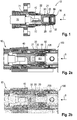
- a first embodiment of a connector 10 according to the invention is shown in a longitudinal sectional view.
- the connector 10 consists of an inner conductor contact 20, which is circulated by an insulator part 30 made of a non-conductor, such as plastic.
- the insulator part 30 prevents the inner conductor contact 20 from coming into electrical contact with an outer conductor part 40 of the connector 10.
- the connector 10 is connected to a coaxial cable 70, wherein the shield 71 of the coaxial cable 70 is electrically coupled to the outer conductor portion 40 of the connector and the inner conductor 72 of the coaxial cable 70 is electrically coupled to the inner conductor contact 20 of the connector 10, for example by soldering or crimping ,
- the inner conductor contact 20 is plug-shaped as a socket formed with a contact spring into which a contact element 101 of a mating connector 100 in the form of a contact pin for making an electrical contact can be inserted.
- a contact element 101 of a mating connector 100 in the form of a contact pin for making an electrical contact can be inserted.
- FIGS. 2a and 2b is the entire connector of connector 10 and associated mating connector 100 shown.
- the inner conductor contact 20 When assembling the connector 10, the inner conductor contact 20 is first connected to the inner conductor 72 of the coaxial cable 70, for example by soldering. Subsequently, the inner conductor contact 20 is inserted into the insulator part 30 until a projection of the insulator part 30 engages in a recess 25 of the inner conductor contact 20.
- the axial dimension of the recess 25 is set up such that a relative movement between insulator part 30 and inner conductor contact 20 within the framework of a predetermined axial play 21 is possible. This facilitates the attachment of the insulator part 30 to the inner conductor contact 20.
- the outer conductor part 40 of the connector for example, by pressing or crimping attached to this cable assembly, so that the outer conductor part 40, the outer conductor 71 of the cable 70 electrically contacted.
- the outer conductor part 40 is movable relative to the insulator part 30.
- the axial games 21, 22 allow for conventional connectors even after pairing with the complementary mating connector still relative movements between the inner conductor contact 20, the insulator part 30 and the outer conductor part 40, which has an increased material wear result, especially if the connector high mechanical loads such is exposed to vibrations.
- an elastically compressible damping element 50 is provided on the connector 10 according to the invention.
- This is compressed, whereby the mobility of the inner conductor contact 20 with respect to.
- the insulator portion 30 and / or the mobility of the insulator part with respect to the outer conductor part 40 is reduced or eliminated altogether.
- the finished plug state with completely eliminated axial play 21, 22 is in Fig. 2b shown while in Fig. 2a a position in the course of insertion of the mating connector 100 is shown, in which the counter-pressure surface 105 of the mating connector 100 while already applied to the damping element 50, but this is not fully compressed.
- the damping element 50 is provided on the connector 10 in such a way that it indirectly transmits the pressure emitted by the mating connector 100 during insertion to the inner conductor contact 20 and directly to the insulator part 30.
- the inner conductor contact 20, the insulator part 30 and the outer conductor part 40 are pushed together in the course of the insertion process, so that the axial Games 21 and 22 are eliminated and a rigid and immovable connection between the inner conductor contact 20, the insulator part 30 and the outer conductor contact is made.
- the damping element 50 forms the leading during insertion of the mating connector front surface of the connector to which by the in the FIGS. 2a and 2b shown counter-pressure surface 105 of the mating connector 100 pressure is exercisable.
- the front surface of the damping element 50 is not flat, but arranged convexly curved, so that in the course of the insertion process first a portion 55 of high material density comes into contact with the counter-pressure surface 105 and the sliding member 50 urges in the direction of the inner conductor contact 20. Subsequently, a portion 56 of low material density which bears directly against the insulator part 30 comes into contact with the counter-pressure surface 105 and presses the insulator part in the direction of the outer conductor part 40. Alternatively or additionally, the insulator part 30 becomes indirectly via the inner conductor part 20 in the direction of a contact surface of the outer conductor part 40 pressed.
- the connector 10 and the Gegenteckverbinder 100 form-locking or non-positively acting connecting means, such as screws, brackets or clamps, by means of which the mating connector, starting from the position according to Fig. 2a in the position according to Fig. 2b can be pulled.
- the connecting means also prevent accidental release of the connector.
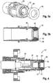
- Fig. 4 shows a slightly modified embodiment of a connector 10 'according to the invention, in which the sliding member 60', on the front end of which Damping element 50 is sprayed, is not held axially displaceable in a guide groove of the insulator member 30, but in a radial guide 32 ', which rests radially outward on the sliding member 60'.
- the rear end 61 of the sliding member 60 ' abuts the inner conductor contact 20, while the damping element 50 formed as a soft component can not come into direct electrical contact with a current-carrying part.
- Fig. 5 shows a second embodiment of a connector 10 "according to the invention.
- This connector is designed as an angle plug or an angle bushing, in which the main axis H of the inner conductor contact 120 or the insulator part 130 transversely, in particular perpendicular to the insertion direction S. In this way, the inner conductor perpendicular to the insertion direction S.
- the inner conductor contact 120 of the second embodiment has, on the one hand, a contact element 122 with contact spring for contacting one or more contact pins 101 'of the mating connector 100' and, on the other hand, a rod-shaped extending along the main axis H starting from the contact element 122 Ladder part 121 which is connectable to the inner conductor 72 of the coaxial cable 70.
- the inner conductor contact 120 is first connected to the inner conductor 72 of the coaxial cable to produce the connector 10 ", then the insulator part 130 is attached to the inner conductor contact 120.
- the arrangement of insulator part 130 and inner conductor contact 120 is along the main axis H perpendicular to the Plug-in direction S extends, inserted into a pipe section 141 of the outer conductor part 140 (see Fig. 8 ).
- a damping element 51 is arranged in the form of an elastically compressible soft component.
- the connector may also have more than one, for example. Two or three damping elements 51.
- the damping element 51 is substantially disc-shaped and has a central portion with a larger dimension in the insertion direction S as the edge portions of the damping element 51. In other words, a curvature of the damping element 51 projects into a mounting space of the outer conductor part 140 for receiving the insulator part 130.
- connection position the insulator part 130 is substantially immovable with respect to.
- the outer conductor part 140 is arranged. Strong vibrations are damped in this connection position by the damping element 51, whereby wear of insulator part 130 and outer conductor part 140 is reliably minimized.
- the damping element 50, 51 is not necessarily annular or disc-shaped.
- a connector depending on the size and number of inner conductor contacts, have more than one damping element. According to the invention it is important that the damping element is provided on the connector so that it is compressed elastically only when mating with the mating connector, and a wear-promoting mobility between the insulator part, the inner conductor contact and the outer conductor part is thus eliminated only during manufacture of the finished connector.
Landscapes
- Connector Housings Or Holding Contact Members (AREA)
- Coupling Device And Connection With Printed Circuit (AREA)
- Details Of Connecting Devices For Male And Female Coupling (AREA)
Applications Claiming Priority (2)
| Application Number | Priority Date | Filing Date | Title |
|---|---|---|---|
| DE202015001331.7U DE202015001331U1 (de) | 2015-02-19 | 2015-02-19 | Steckverbinder mit Dämpfungselement |
| PCT/EP2016/000184 WO2016131526A1 (de) | 2015-02-19 | 2016-02-04 | Steckverbinder mit dämpfungselement |
Publications (2)
| Publication Number | Publication Date |
|---|---|
| EP3259810A1 EP3259810A1 (de) | 2017-12-27 |
| EP3259810B1 true EP3259810B1 (de) | 2019-09-04 |
Family
ID=53184650
Family Applications (1)
| Application Number | Title | Priority Date | Filing Date |
|---|---|---|---|
| EP16703064.2A Active EP3259810B1 (de) | 2015-02-19 | 2016-02-04 | Steckverbinder mit dämpfungselement |
Country Status (8)
| Country | Link |
|---|---|
| US (1) | US10305219B2 (enExample) |
| EP (1) | EP3259810B1 (enExample) |
| JP (1) | JP6571787B2 (enExample) |
| KR (1) | KR20170117018A (enExample) |
| CN (1) | CN107112681B (enExample) |
| CA (1) | CA2968296A1 (enExample) |
| DE (1) | DE202015001331U1 (enExample) |
| WO (1) | WO2016131526A1 (enExample) |
Families Citing this family (7)
| Publication number | Priority date | Publication date | Assignee | Title |
|---|---|---|---|---|
| EP3174166B1 (en) | 2015-11-25 | 2018-11-14 | ODU GmbH & Co KG. | Damping element for providing axial damping in a plug-in connector, plug-in connector and method for forming a plug-in connector |
| CN109804510B (zh) * | 2016-09-23 | 2021-05-11 | 史陶比尔电子连接器股份公司 | 受保护的插头 |
| KR102386790B1 (ko) * | 2017-09-22 | 2022-04-15 | 하르팅 에렉트릭 게엠베하 운트 코우. 카게 | 절연 부싱을 포함한 고전류 커넥터 |
| DE102018127720B3 (de) | 2018-11-07 | 2019-12-05 | Harting Electric Gmbh & Co. Kg | Hochstromsteckverbinder und Steckverbindersystem |
| KR102633954B1 (ko) * | 2018-12-12 | 2024-02-05 | 현대자동차주식회사 | 통합형 다극 커넥터 |
| JP7147796B2 (ja) * | 2020-02-27 | 2022-10-05 | Smk株式会社 | コネクタ |
| DE102021107308A1 (de) * | 2021-03-24 | 2022-09-29 | Amphenol-Tuchel Electronics Gesellschaft mit beschränkter Haftung | Steckverbinderstecker mit gesteigerter Vibrationsfestigkeit |
Family Cites Families (21)
| Publication number | Priority date | Publication date | Assignee | Title |
|---|---|---|---|---|
| US3017597A (en) | 1958-11-13 | 1962-01-16 | Pyle National Co | Electrical connector |
| DE2421321C3 (de) * | 1974-05-02 | 1978-05-11 | Georg Dipl.-Ing. Dr.-Ing. 8152 Feldkirchen-Westerham Spinner | Abgedichtete koaxiale Steckverbindungseinrichtung |
| AT371659B (de) * | 1981-10-15 | 1983-07-25 | Akg Akustische Kino Geraete | Kopplungsglied fuer ein stabfoermiges kondensatormikrophon |
| US4451103A (en) * | 1981-12-14 | 1984-05-29 | Rockwell International Corporation | Connector assembly |
| US5588852A (en) * | 1995-03-21 | 1996-12-31 | The Whitaker Corporation | Electrical connector having socket contacts with safety shields |
| GB9706155D0 (en) | 1997-03-25 | 1997-05-14 | Decolletage Sa Saint Maurice | Coaxial connector for circuit board |
| US6450829B1 (en) * | 2000-12-15 | 2002-09-17 | Tyco Electronics Canada, Ltd. | Snap-on plug coaxial connector |
| DE10140177B4 (de) * | 2001-08-22 | 2006-03-09 | Ballard Power Systems Ag | Verbindungsvorrichtung |
| EP1500169A4 (en) | 2002-04-30 | 2008-12-31 | Corning Gilbert Inc | DEVICE FOR ELECTRIC COUPLING OF A LINEAR LADDER WITH A SURFACE GUIDE AND METHOD THEREFOR |
| US7150562B2 (en) | 2004-09-09 | 2006-12-19 | Finisar Corporation | High voltage cable terminal and clamp system |
| US7309247B1 (en) * | 2006-05-23 | 2007-12-18 | Micro-Coax | Cable interconnect |
| CN2932698Y (zh) * | 2006-07-04 | 2007-08-08 | 富士康(昆山)电脑接插件有限公司 | 电连接器 |
| JP5120036B2 (ja) * | 2008-04-10 | 2013-01-16 | 日立電線株式会社 | コネクタ |
| DE102009043516A1 (de) * | 2009-09-30 | 2011-04-07 | Tyco Electronics Amp Gmbh | Zweiteiliges Kontaktelement für Hochspannungssteckverbinder |
| US8668188B2 (en) * | 2010-08-31 | 2014-03-11 | General Electric Company | Slotted spring vibration isolator |
| DE102011004347A1 (de) * | 2011-02-17 | 2012-08-23 | Tyco Electronics Amp Gmbh | Elektrischer Verbinder und Stecksystem |
| JP2013045527A (ja) * | 2011-08-22 | 2013-03-04 | Sony Corp | 接続ジャック及び電子機器 |
| US9627814B2 (en) | 2012-04-04 | 2017-04-18 | Holland Electronics Llc | Moving part coaxial connectors |
| JP2014123446A (ja) | 2012-12-20 | 2014-07-03 | Sumitomo Wiring Syst Ltd | コネクタ |
| DE202014006815U1 (de) * | 2014-08-21 | 2014-09-09 | Rosenberger Hochfrequenztechnik Gmbh & Co. Kg | Hochstrom-Stecker mit Bügelverschluss |
| DE102014116322B3 (de) * | 2014-11-10 | 2015-08-13 | Lumberg Connect Gmbh | Steckverbinder mit Vibrationssicherung |
-
2015
- 2015-02-19 DE DE202015001331.7U patent/DE202015001331U1/de not_active Expired - Lifetime
-
2016
- 2016-02-04 WO PCT/EP2016/000184 patent/WO2016131526A1/de not_active Ceased
- 2016-02-04 CN CN201680004390.7A patent/CN107112681B/zh active Active
- 2016-02-04 CA CA2968296A patent/CA2968296A1/en not_active Abandoned
- 2016-02-04 KR KR1020177015532A patent/KR20170117018A/ko not_active Withdrawn
- 2016-02-04 EP EP16703064.2A patent/EP3259810B1/de active Active
- 2016-02-04 US US15/545,897 patent/US10305219B2/en active Active
- 2016-02-04 JP JP2017543745A patent/JP6571787B2/ja active Active
Non-Patent Citations (1)
| Title |
|---|
| None * |
Also Published As
| Publication number | Publication date |
|---|---|
| US10305219B2 (en) | 2019-05-28 |
| CN107112681B (zh) | 2018-09-21 |
| US20180261954A1 (en) | 2018-09-13 |
| DE202015001331U1 (de) | 2015-04-15 |
| JP2018507518A (ja) | 2018-03-15 |
| EP3259810A1 (de) | 2017-12-27 |
| WO2016131526A1 (de) | 2016-08-25 |
| JP6571787B2 (ja) | 2019-09-04 |
| CA2968296A1 (en) | 2016-08-25 |
| KR20170117018A (ko) | 2017-10-20 |
| CN107112681A (zh) | 2017-08-29 |
Similar Documents
| Publication | Publication Date | Title |
|---|---|---|
| EP3259810B1 (de) | Steckverbinder mit dämpfungselement | |
| DE102007012124B4 (de) | Kompressionsverbinder für Koaxialkabel | |
| EP3262722B1 (de) | Steckverbindung mit verriegelungsvorrichtung | |
| DE102010037498B4 (de) | Elektrischer Kontakt | |
| EP3266076B1 (de) | Verfahren zur montage eines winkelsteckverbinders und montageeinheit zum herstellen eines winkelsteckverbinders | |
| DE69709271T2 (de) | Elektrischer Steckverbinder für Kabel, Montage und dazugehörige Methode | |
| DE102012209298B4 (de) | Elektrischer Steckverbinder, Steckverbinderanordnung sowie Verfahren zum Montieren des Steckverbinders | |
| EP0772261A2 (de) | Koaxial-Steckverbindung | |
| DE102016006598A1 (de) | Steckverbinder | |
| EP2076943A1 (de) | Xlr-kabelsteckverbinder | |
| EP3895256B1 (de) | Rundsteckverbinder mit verriegelung | |
| EP3443620A1 (de) | Steckverbinder | |
| EP4000139B1 (de) | Kontaktelement | |
| EP3084896B1 (de) | Steckverbinderanordnung | |
| WO2014117926A1 (de) | Steckverbinder | |
| DE102023105968A1 (de) | Geschirmter PushPull-Stecker mit Schirmfeder | |
| EP1641086B1 (de) | Koaxialsteckverbinder | |
| AT522822A1 (de) | Elektrischer Steckverbinder | |
| EP1837955B1 (de) | Halteschutzbuchse für einen Steckverbinder | |
| DE102017222809A1 (de) | Elektrischer Steckverbinder und Steckverbindung | |
| DE102009039354B4 (de) | Elektrischer Steckverbinder | |
| DE202012101303U1 (de) | Steckverbindergehäuse | |
| WO2023079168A1 (de) | Kupplung für zwei steckverbinder | |
| EP1744406B1 (de) | Buchsenkontakt zur Herstellung einer elektrischen Steckverbindung mit einem Gegenkontakt sowie Steckverbinder mit einem Buchsenkontakt | |
| DE10346367B4 (de) | Freidrehbarer HF-Winkelsteckverbinder |
Legal Events
| Date | Code | Title | Description |
|---|---|---|---|
| STAA | Information on the status of an ep patent application or granted ep patent |
Free format text: STATUS: THE INTERNATIONAL PUBLICATION HAS BEEN MADE |
|
| PUAI | Public reference made under article 153(3) epc to a published international application that has entered the european phase |
Free format text: ORIGINAL CODE: 0009012 |
|
| STAA | Information on the status of an ep patent application or granted ep patent |
Free format text: STATUS: REQUEST FOR EXAMINATION WAS MADE |
|
| 17P | Request for examination filed |
Effective date: 20170516 |
|
| AK | Designated contracting states |
Kind code of ref document: A1 Designated state(s): AL AT BE BG CH CY CZ DE DK EE ES FI FR GB GR HR HU IE IS IT LI LT LU LV MC MK MT NL NO PL PT RO RS SE SI SK SM TR |
|
| AX | Request for extension of the european patent |
Extension state: BA ME |
|
| DAV | Request for validation of the european patent (deleted) | ||
| DAX | Request for extension of the european patent (deleted) | ||
| REG | Reference to a national code |
Ref country code: DE Ref legal event code: R079 Ref document number: 502016006416 Country of ref document: DE Free format text: PREVIOUS MAIN CLASS: H01R0024380000 Ipc: H01R0013530000 |
|
| GRAP | Despatch of communication of intention to grant a patent |
Free format text: ORIGINAL CODE: EPIDOSNIGR1 |
|
| STAA | Information on the status of an ep patent application or granted ep patent |
Free format text: STATUS: GRANT OF PATENT IS INTENDED |
|
| RIC1 | Information provided on ipc code assigned before grant |
Ipc: H01R 13/502 20060101ALN20190319BHEP Ipc: H01R 103/00 20060101ALN20190319BHEP Ipc: H01R 24/38 20110101ALI20190319BHEP Ipc: H01R 13/53 20060101AFI20190319BHEP |
|
| INTG | Intention to grant announced |
Effective date: 20190404 |
|
| GRAS | Grant fee paid |
Free format text: ORIGINAL CODE: EPIDOSNIGR3 |
|
| GRAA | (expected) grant |
Free format text: ORIGINAL CODE: 0009210 |
|
| STAA | Information on the status of an ep patent application or granted ep patent |
Free format text: STATUS: THE PATENT HAS BEEN GRANTED |
|
| AK | Designated contracting states |
Kind code of ref document: B1 Designated state(s): AL AT BE BG CH CY CZ DE DK EE ES FI FR GB GR HR HU IE IS IT LI LT LU LV MC MK MT NL NO PL PT RO RS SE SI SK SM TR |
|
| REG | Reference to a national code |
Ref country code: GB Ref legal event code: FG4D Free format text: NOT ENGLISH |
|
| REG | Reference to a national code |
Ref country code: CH Ref legal event code: EP |
|
| REG | Reference to a national code |
Ref country code: AT Ref legal event code: REF Ref document number: 1176689 Country of ref document: AT Kind code of ref document: T Effective date: 20190915 |
|
| REG | Reference to a national code |
Ref country code: DE Ref legal event code: R096 Ref document number: 502016006416 Country of ref document: DE |
|
| REG | Reference to a national code |
Ref country code: IE Ref legal event code: FG4D Free format text: LANGUAGE OF EP DOCUMENT: GERMAN |
|
| REG | Reference to a national code |
Ref country code: SE Ref legal event code: TRGR |
|
| REG | Reference to a national code |
Ref country code: NL Ref legal event code: MP Effective date: 20190904 |
|
| REG | Reference to a national code |
Ref country code: LT Ref legal event code: MG4D |
|
| PG25 | Lapsed in a contracting state [announced via postgrant information from national office to epo] |
Ref country code: NO Free format text: LAPSE BECAUSE OF FAILURE TO SUBMIT A TRANSLATION OF THE DESCRIPTION OR TO PAY THE FEE WITHIN THE PRESCRIBED TIME-LIMIT Effective date: 20191204 Ref country code: HR Free format text: LAPSE BECAUSE OF FAILURE TO SUBMIT A TRANSLATION OF THE DESCRIPTION OR TO PAY THE FEE WITHIN THE PRESCRIBED TIME-LIMIT Effective date: 20190904 Ref country code: FI Free format text: LAPSE BECAUSE OF FAILURE TO SUBMIT A TRANSLATION OF THE DESCRIPTION OR TO PAY THE FEE WITHIN THE PRESCRIBED TIME-LIMIT Effective date: 20190904 Ref country code: LT Free format text: LAPSE BECAUSE OF FAILURE TO SUBMIT A TRANSLATION OF THE DESCRIPTION OR TO PAY THE FEE WITHIN THE PRESCRIBED TIME-LIMIT Effective date: 20190904 Ref country code: BG Free format text: LAPSE BECAUSE OF FAILURE TO SUBMIT A TRANSLATION OF THE DESCRIPTION OR TO PAY THE FEE WITHIN THE PRESCRIBED TIME-LIMIT Effective date: 20191204 |
|
| PG25 | Lapsed in a contracting state [announced via postgrant information from national office to epo] |
Ref country code: AL Free format text: LAPSE BECAUSE OF FAILURE TO SUBMIT A TRANSLATION OF THE DESCRIPTION OR TO PAY THE FEE WITHIN THE PRESCRIBED TIME-LIMIT Effective date: 20190904 Ref country code: ES Free format text: LAPSE BECAUSE OF FAILURE TO SUBMIT A TRANSLATION OF THE DESCRIPTION OR TO PAY THE FEE WITHIN THE PRESCRIBED TIME-LIMIT Effective date: 20190904 Ref country code: LV Free format text: LAPSE BECAUSE OF FAILURE TO SUBMIT A TRANSLATION OF THE DESCRIPTION OR TO PAY THE FEE WITHIN THE PRESCRIBED TIME-LIMIT Effective date: 20190904 Ref country code: RS Free format text: LAPSE BECAUSE OF FAILURE TO SUBMIT A TRANSLATION OF THE DESCRIPTION OR TO PAY THE FEE WITHIN THE PRESCRIBED TIME-LIMIT Effective date: 20190904 Ref country code: GR Free format text: LAPSE BECAUSE OF FAILURE TO SUBMIT A TRANSLATION OF THE DESCRIPTION OR TO PAY THE FEE WITHIN THE PRESCRIBED TIME-LIMIT Effective date: 20191205 |
|
| PG25 | Lapsed in a contracting state [announced via postgrant information from national office to epo] |
Ref country code: PT Free format text: LAPSE BECAUSE OF FAILURE TO SUBMIT A TRANSLATION OF THE DESCRIPTION OR TO PAY THE FEE WITHIN THE PRESCRIBED TIME-LIMIT Effective date: 20200106 Ref country code: RO Free format text: LAPSE BECAUSE OF FAILURE TO SUBMIT A TRANSLATION OF THE DESCRIPTION OR TO PAY THE FEE WITHIN THE PRESCRIBED TIME-LIMIT Effective date: 20190904 Ref country code: NL Free format text: LAPSE BECAUSE OF FAILURE TO SUBMIT A TRANSLATION OF THE DESCRIPTION OR TO PAY THE FEE WITHIN THE PRESCRIBED TIME-LIMIT Effective date: 20190904 Ref country code: PL Free format text: LAPSE BECAUSE OF FAILURE TO SUBMIT A TRANSLATION OF THE DESCRIPTION OR TO PAY THE FEE WITHIN THE PRESCRIBED TIME-LIMIT Effective date: 20190904 Ref country code: EE Free format text: LAPSE BECAUSE OF FAILURE TO SUBMIT A TRANSLATION OF THE DESCRIPTION OR TO PAY THE FEE WITHIN THE PRESCRIBED TIME-LIMIT Effective date: 20190904 |
|
| PG25 | Lapsed in a contracting state [announced via postgrant information from national office to epo] |
Ref country code: SM Free format text: LAPSE BECAUSE OF FAILURE TO SUBMIT A TRANSLATION OF THE DESCRIPTION OR TO PAY THE FEE WITHIN THE PRESCRIBED TIME-LIMIT Effective date: 20190904 Ref country code: IS Free format text: LAPSE BECAUSE OF FAILURE TO SUBMIT A TRANSLATION OF THE DESCRIPTION OR TO PAY THE FEE WITHIN THE PRESCRIBED TIME-LIMIT Effective date: 20200224 Ref country code: SK Free format text: LAPSE BECAUSE OF FAILURE TO SUBMIT A TRANSLATION OF THE DESCRIPTION OR TO PAY THE FEE WITHIN THE PRESCRIBED TIME-LIMIT Effective date: 20190904 Ref country code: CZ Free format text: LAPSE BECAUSE OF FAILURE TO SUBMIT A TRANSLATION OF THE DESCRIPTION OR TO PAY THE FEE WITHIN THE PRESCRIBED TIME-LIMIT Effective date: 20190904 |
|
| REG | Reference to a national code |
Ref country code: DE Ref legal event code: R097 Ref document number: 502016006416 Country of ref document: DE |
|
| PLBE | No opposition filed within time limit |
Free format text: ORIGINAL CODE: 0009261 |
|
| STAA | Information on the status of an ep patent application or granted ep patent |
Free format text: STATUS: NO OPPOSITION FILED WITHIN TIME LIMIT |
|
| PG2D | Information on lapse in contracting state deleted |
Ref country code: IS |
|
| PG25 | Lapsed in a contracting state [announced via postgrant information from national office to epo] |
Ref country code: DK Free format text: LAPSE BECAUSE OF FAILURE TO SUBMIT A TRANSLATION OF THE DESCRIPTION OR TO PAY THE FEE WITHIN THE PRESCRIBED TIME-LIMIT Effective date: 20190904 Ref country code: IS Free format text: LAPSE BECAUSE OF FAILURE TO SUBMIT A TRANSLATION OF THE DESCRIPTION OR TO PAY THE FEE WITHIN THE PRESCRIBED TIME-LIMIT Effective date: 20200105 |
|
| 26N | No opposition filed |
Effective date: 20200605 |
|
| PG25 | Lapsed in a contracting state [announced via postgrant information from national office to epo] |
Ref country code: SI Free format text: LAPSE BECAUSE OF FAILURE TO SUBMIT A TRANSLATION OF THE DESCRIPTION OR TO PAY THE FEE WITHIN THE PRESCRIBED TIME-LIMIT Effective date: 20190904 |
|
| REG | Reference to a national code |
Ref country code: CH Ref legal event code: PL |
|
| REG | Reference to a national code |
Ref country code: BE Ref legal event code: MM Effective date: 20200229 |
|
| PG25 | Lapsed in a contracting state [announced via postgrant information from national office to epo] |
Ref country code: MC Free format text: LAPSE BECAUSE OF FAILURE TO SUBMIT A TRANSLATION OF THE DESCRIPTION OR TO PAY THE FEE WITHIN THE PRESCRIBED TIME-LIMIT Effective date: 20190904 Ref country code: LU Free format text: LAPSE BECAUSE OF NON-PAYMENT OF DUE FEES Effective date: 20200204 |
|
| PG25 | Lapsed in a contracting state [announced via postgrant information from national office to epo] |
Ref country code: LI Free format text: LAPSE BECAUSE OF NON-PAYMENT OF DUE FEES Effective date: 20200229 Ref country code: CH Free format text: LAPSE BECAUSE OF NON-PAYMENT OF DUE FEES Effective date: 20200229 |
|
| PG25 | Lapsed in a contracting state [announced via postgrant information from national office to epo] |
Ref country code: IE Free format text: LAPSE BECAUSE OF NON-PAYMENT OF DUE FEES Effective date: 20200204 |
|
| PG25 | Lapsed in a contracting state [announced via postgrant information from national office to epo] |
Ref country code: BE Free format text: LAPSE BECAUSE OF NON-PAYMENT OF DUE FEES Effective date: 20200229 |
|
| REG | Reference to a national code |
Ref country code: AT Ref legal event code: MM01 Ref document number: 1176689 Country of ref document: AT Kind code of ref document: T Effective date: 20210204 |
|
| PG25 | Lapsed in a contracting state [announced via postgrant information from national office to epo] |
Ref country code: AT Free format text: LAPSE BECAUSE OF NON-PAYMENT OF DUE FEES Effective date: 20210204 |
|
| PG25 | Lapsed in a contracting state [announced via postgrant information from national office to epo] |
Ref country code: TR Free format text: LAPSE BECAUSE OF FAILURE TO SUBMIT A TRANSLATION OF THE DESCRIPTION OR TO PAY THE FEE WITHIN THE PRESCRIBED TIME-LIMIT Effective date: 20190904 Ref country code: MT Free format text: LAPSE BECAUSE OF FAILURE TO SUBMIT A TRANSLATION OF THE DESCRIPTION OR TO PAY THE FEE WITHIN THE PRESCRIBED TIME-LIMIT Effective date: 20190904 Ref country code: CY Free format text: LAPSE BECAUSE OF FAILURE TO SUBMIT A TRANSLATION OF THE DESCRIPTION OR TO PAY THE FEE WITHIN THE PRESCRIBED TIME-LIMIT Effective date: 20190904 |
|
| PG25 | Lapsed in a contracting state [announced via postgrant information from national office to epo] |
Ref country code: MK Free format text: LAPSE BECAUSE OF FAILURE TO SUBMIT A TRANSLATION OF THE DESCRIPTION OR TO PAY THE FEE WITHIN THE PRESCRIBED TIME-LIMIT Effective date: 20190904 |
|
| P01 | Opt-out of the competence of the unified patent court (upc) registered |
Effective date: 20230527 |
|
| REG | Reference to a national code |
Ref country code: DE Ref legal event code: R082 Ref document number: 502016006416 Country of ref document: DE Representative=s name: KANDLBINDER, MARKUS, DIPL.-PHYS., DE |
|
| PGFP | Annual fee paid to national office [announced via postgrant information from national office to epo] |
Ref country code: DE Payment date: 20250226 Year of fee payment: 10 |
|
| PGFP | Annual fee paid to national office [announced via postgrant information from national office to epo] |
Ref country code: SE Payment date: 20250224 Year of fee payment: 10 |
|
| PGFP | Annual fee paid to national office [announced via postgrant information from national office to epo] |
Ref country code: FR Payment date: 20250224 Year of fee payment: 10 |
|
| PGFP | Annual fee paid to national office [announced via postgrant information from national office to epo] |
Ref country code: IT Payment date: 20250225 Year of fee payment: 10 Ref country code: GB Payment date: 20250218 Year of fee payment: 10 |