EP3258079A1 - Supercharging system of internal-combustion engine and method for controlling supercharging system - Google Patents
Supercharging system of internal-combustion engine and method for controlling supercharging system Download PDFInfo
- Publication number
- EP3258079A1 EP3258079A1 EP15881911.0A EP15881911A EP3258079A1 EP 3258079 A1 EP3258079 A1 EP 3258079A1 EP 15881911 A EP15881911 A EP 15881911A EP 3258079 A1 EP3258079 A1 EP 3258079A1
- Authority
- EP
- European Patent Office
- Prior art keywords
- operation mode
- exhaust
- combustion engine
- internal combustion
- state
- Prior art date
- Legal status (The legal status is an assumption and is not a legal conclusion. Google has not performed a legal analysis and makes no representation as to the accuracy of the status listed.)
- Withdrawn
Links
Images


Classifications
-
- F—MECHANICAL ENGINEERING; LIGHTING; HEATING; WEAPONS; BLASTING
- F02—COMBUSTION ENGINES; HOT-GAS OR COMBUSTION-PRODUCT ENGINE PLANTS
- F02B—INTERNAL-COMBUSTION PISTON ENGINES; COMBUSTION ENGINES IN GENERAL
- F02B37/00—Engines characterised by provision of pumps driven at least for part of the time by exhaust
- F02B37/013—Engines characterised by provision of pumps driven at least for part of the time by exhaust with exhaust-driven pumps arranged in series
-
- F—MECHANICAL ENGINEERING; LIGHTING; HEATING; WEAPONS; BLASTING
- F02—COMBUSTION ENGINES; HOT-GAS OR COMBUSTION-PRODUCT ENGINE PLANTS
- F02B—INTERNAL-COMBUSTION PISTON ENGINES; COMBUSTION ENGINES IN GENERAL
- F02B37/00—Engines characterised by provision of pumps driven at least for part of the time by exhaust
- F02B37/12—Control of the pumps
- F02B37/16—Control of the pumps by bypassing charging air
-
- F—MECHANICAL ENGINEERING; LIGHTING; HEATING; WEAPONS; BLASTING
- F02—COMBUSTION ENGINES; HOT-GAS OR COMBUSTION-PRODUCT ENGINE PLANTS
- F02B—INTERNAL-COMBUSTION PISTON ENGINES; COMBUSTION ENGINES IN GENERAL
- F02B37/00—Engines characterised by provision of pumps driven at least for part of the time by exhaust
- F02B37/12—Control of the pumps
- F02B37/18—Control of the pumps by bypassing exhaust from the inlet to the outlet of turbine or to the atmosphere
-
- F—MECHANICAL ENGINEERING; LIGHTING; HEATING; WEAPONS; BLASTING
- F02—COMBUSTION ENGINES; HOT-GAS OR COMBUSTION-PRODUCT ENGINE PLANTS
- F02D—CONTROLLING COMBUSTION ENGINES
- F02D41/00—Electrical control of supply of combustible mixture or its constituents
- F02D41/0002—Controlling intake air
- F02D41/0007—Controlling intake air for control of turbo-charged or super-charged engines
-
- Y—GENERAL TAGGING OF NEW TECHNOLOGICAL DEVELOPMENTS; GENERAL TAGGING OF CROSS-SECTIONAL TECHNOLOGIES SPANNING OVER SEVERAL SECTIONS OF THE IPC; TECHNICAL SUBJECTS COVERED BY FORMER USPC CROSS-REFERENCE ART COLLECTIONS [XRACs] AND DIGESTS
- Y02—TECHNOLOGIES OR APPLICATIONS FOR MITIGATION OR ADAPTATION AGAINST CLIMATE CHANGE
- Y02T—CLIMATE CHANGE MITIGATION TECHNOLOGIES RELATED TO TRANSPORTATION
- Y02T10/00—Road transport of goods or passengers
- Y02T10/10—Internal combustion engine [ICE] based vehicles
- Y02T10/12—Improving ICE efficiencies
Definitions
- the present disclosure relates to a multi-stage supercharging system of an internal combustion engine and a method of controlling the supercharging system.
- a widely-used turbocharger supplies air (supercharging) to an internal combustion engine with a turbo compressor coupled to an exhaust turbine by driving the exhaust turbine with exhaust gas of the internal combustion engine. Further, to improve the supercharging efficiency of the internal combustion engine, in a known two-stage turbo system, a turbocharger is provided for each of the high-pressure side and the low-pressure side to perform two-stage supercharging.
- Patent Document 1 discloses, for such a type of two-stage turbo system, performing a switch control on an exhaust flow passage by executing a plurality of operation modes selectively in response to an operational state.
- a plurality of valves are disposed in the exhaust flow passage, and each operation mode controls a different valve.
- Patent Document 1 JP2005-146906A
- the operational state is determined on the basis of the engine rotation speed and the fuel injection amount.
- the engine rotation speed and the fuel injection amount are difficult to maintain to be strictly constant due to the characteristics of the engine, and may change more than a little.
- the operational state is in the vicinity of a boundary between more than one operation modes, for instance, the above change may bring about hunting, which may make the control unstable.
- An object of at least one embodiment of the present invention is to provide a supercharging system of an internal combustion engine and a control method of a supercharging system, whereby a plurality of operation modes can be switched stably when performing a switch control on the plurality of operation modes on the basis of an operational state of the internal combustion engine.
- a supercharging system for an internal combustion engine comprises: an internal combustion engine; a plurality of turbochargers configured to be capable of multi-stage supercharging of intake gas for the internal combustion engine; a state-amount detection part configured to detect a state amount related to an operational state of the internal combustion engine; an intake flow-passage switching valve configured to be capable of switching an intake flow passage of the intake gas of the internal combustion engine; an exhaust flow-passage switching valve configured to be capable of switching an exhaust flow passage of exhaust gas of the internal combustion engine; and a control part configured to control at least one of the intake flow-passage switching valve or the exhaust flow-passage switching valve so that an operation mode transitions from a first operation mode to a second operation mode, from among a plurality of operation modes determined in advance corresponding to the operational state, if the state amount is at least a threshold selected corresponding to the state amount on the basis of a first threshold function, and so that the operation mode transitions from the second operation mode to the first operation mode if the
- a threshold selected corresponding to the state amount on the basis of the first threshold function which is a reference for transition from the first operation mode to the second operation mode, and a threshold selected corresponding to the state amount on the basis of the second threshold function which is a reference for transition from the second operation mode to a low rotation mode are set to be different from each other.
- the first threshold function and the second threshold function having a difference therebetween, upon transition from one of the second operation mode and the first operation mode to another, it is possible to prevent occurrence of hunting caused by returning transition of the operation mode from the other one to the previous one due to a change in the state amount.
- the operational state is determined by a plurality of state amounts.
- the plurality of turbochargers comprises: a first turbocharger; and a second turbocharger including an exhaust turbine disposed downstream of an exhaust turbine of the first turbocharger in the exhaust flow passage.
- the intake flow passage comprises: an intake in-line flow passage connected from outside to the internal combustion engine via a turbo compressor of the first turbocharger and a turbo compressor of the second turbocharger; and an intake bypass flow passage connecting an outlet side of the turbo compressor of the first turbocharger and an outlet side of the turbo compressor of the second turbocharger.
- the exhaust flow passage includes: an exhaust in-line flow passage extending from the internal combustion engine to the outside via the exhaust turbine of the second turbocharger and the exhaust turbine of the first turbocharger; an exhaust first bypass flow passage connecting an inlet side of the exhaust turbine of the second turbocharger and an inlet side of the turbine of the first turbocharger; and an exhaust second bypass flow passage connecting an outlet side of the exhaust turbine of the second turbocharger and a downstream side of a downstream connection point between the exhaust first bypass flow passage and the exhaust in-line flow passage.
- the intake flow-passage switching valve is a compressor bypass valve disposed in the intake bypass flow passage.
- the exhaust switching valve comprises an exhaust flow-rate control valve disposed in the exhaust first bypass flow passage, and a waste gate valve disposed in the exhaust second bypass flow passage.
- the controller is configured to control the operation mode to be capable of transitioning between: a first operation mode in which the compressor bypass valve, the exhaust-flow rate control valve, and the waste gate valve are controlled to be in a closed state; a second operation mode in which an opening degree of the compressor bypass valve is controlled while the exhaust flow-rate control valve and the waste gate valve are controlled to be in the closed state when the internal combustion engine is at a high-rotation side compared to the first operation mode; a third operation mode in which the compressor bypass valve and the exhaust-flow rate control valve are controlled to be in an open state while the waste gate valve is controlled to be in the closed state when the internal combustion engine is at a high-rotation side compared to the second operation mode; and a fourth operation mode in which an opening degree of the waste gate valve is controlled while the compressor bypass valve and the exhaust flow-rate control valve are controlled to be in the open state when the internal combustion engine is at a high-rotation side compared to the third operation mode.
- a method of controlling a supercharging system for an internal combustion engine comprising: an internal combustion engine; a plurality of turbochargers configured to be capable of multi-stage supercharging of intake gas for the internal combustion engine; a state-amount detection part configured to detect a state amount related to an operational state of the internal combustion engine; an intake flow-passage switching valve configured to be capable of switching an intake flow passage of the intake gas of the internal combustion engine; an exhaust flow-passage switching valve configured to be capable of switching an exhaust flow passage of exhaust gas of the internal combustion engine, according to at least one embodiment of the present invention, to solve the above problem, comprises: a state amount detection step of detecting the state amount related to the operational state of the internal combustion engine with the state amount detection part; and a control step of controlling at least one of the intake flow-passage switching valve or the exhaust flow-passage switching valve so that an operation mode transitions from a first operation mode to a second operation mode, from among a plurality of operation modes determined in advance corresponding to the operational state, if the state amount
- the above configuration (6) can be suitably performed by the above described supercharging system (including the above various embodiments) of the internal combustion engine.
- a supercharging system of an internal combustion engine and a control method of a supercharging system whereby a plurality of operation modes can be switched stably when performing a switch control on the plurality of operation modes on the basis of an operational state of the internal combustion engine.
- an expression of relative or absolute arrangement such as “in a direction”, “along a direction”, “parallel”, “orthogonal”, “centered”, “concentric” and “coaxial” shall not be construed as indicating only the arrangement in a strict literal sense, but also includes a state where the arrangement is relatively displaced by a tolerance, or by an angle or a distance whereby it is possible to achieve the same function.
- an expression of a shape such as a rectangular shape or a cylindrical shape shall not be construed as only the geometrically strict shape, but also includes a shape with unevenness or chamfered corners within the range in which the same effect can be achieved.
- FIG. 1 is a schematic diagram illustrating an overall configuration of a supercharging system (two-stage turbo system) 2 of an internal combustion engine 1 according to an embodiment of the present invention.
- the internal combustion engine 1 is a four-cylinder diesel engine, for instance. Intake air introduced from an intake system 4 undergoes compressed ignition combustion with fuel supplied from a common rail (not depicted) in a combustion chamber 6, and thereby power is generated. Exhaust gas produced in the combustion chamber 6 is discharged outside via an exhaust system 8.
- the supercharging system 2 includes the first turbocharger 10A and the second turbocharger 10B.
- the first turbocharger 10A includes a turbo compressor 12A and an exhaust turbine 14A.
- the second turbocharger 10B includes a turbo compressor 12B and an exhaust turbine 14B.
- the two turbochargers 10A, 10B are turbochargers having substantially the same turbine capacity.
- the first turbocharger 10A on the upstream side of the exhaust flow passage functions as a high-pressure turbocharger
- the second turbocharger 10B on the downstream side of the exhaust flow passage functions as a low-pressure turbocharger.
- the intake system 4 includes an intake in-line flow passage T1 connected to the internal combustion engine 1 via the turbo compressor 12A of the first turbocharger 10A and the turbo compressor 12B of the second turbocharger 10B from outside, and an intake bypass flow passage T2 connecting an outlet side of the turbo compressor 12A of the first turbocharger 10A and an outlet side of the turbo compressor 12B of the second turbocharger 10B.
- a compressor bypass valve V1 which is an intake flow-passage switching valve, is disposed in the intake bypass flow passage T2.
- the compressor bypass valve V1 is a proportional control valve and is configured to be capable of controlling the flow rate continuously in accordance with the opening degree.
- An inter cooler 16 for cooling supply air compressed and heated by a turbocharger is disposed between the internal combustion engine 1 and a downstream merging point 13 of the intake in-line flow passage T1 and the intake bypass flow passage T2. Further, an air cleaner 18 for purifying intake air is disposed in the vicinity of the inlet of the intake system 4.
- the exhaust system 8 includes an exhaust in-line flow passage T3 extending from the internal combustion engine 1 to outside via the exhaust turbine 14B of the second turbocharger 10B and the exhaust turbine 14A of the first turbocharger 10A, an exhaust first bypass flow passage T4 connecting an inlet side of the exhaust turbine 14B of the second turbocharger 10B and an inlet side of the exhaust turbine 14A of the first turbocharger 10A, and an exhaust second bypass flow passage T5 connecting a downstream side of a downstream connection point between the exhaust first bypass flow passage T4 and the exhaust in-line flow passage T3 and the outlet side of the exhaust turbine 14B of the second turbocharger 10B.
- an exhaust flow-rate control valve V2 is disposed in the exhaust first bypass flow passage T4, and a waste-gate valve V3 is disposed in the exhaust second bypass flow passage T5.
- the exhaust flow-rate control valve V2 and the waste-gate valve V3 are both an exhaust switching valve and is configured to be capable of controlling the flow rate continuously in accordance with the opening degree, thus serving as a proportional control valve.
- a noise-canceling muffler 19 is disposed on the downstream side of a downstream merging point 21 between the exhaust in-line flow passage T3 and the exhaust second bypass flow passage T5, in the exhaust system 8.
- the supercharging system 1 includes a controller 20, which is a control unit.
- the controller 20 is a computation processing unit, and includes a computation processing device such as a microprocessor.
- the controller 20 is capable of switching the flow passage of the intake system 4 and the exhaust system 8 by controlling the compressor bypass valve V1, the exhaust flow-rate control valve V2, and the waste-gate valve V3 in accordance with the following first to fourth operation modes.
- the controller 20 includes, to perform the following controls, a state-amount detection part 22 for detecting a state amount related to the operational state of the internal combustion engine 1, and a control part 24 for controlling at least one of the intake flow-passage switch valve or the exhaust flow-passage switch valve.
- FIG. 2 is a graph showing a relationship between an operational state of the internal combustion engine 1 and each operation mode.
- FIG. 3 is a table of control targets in each operation mode.
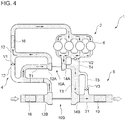
- FIGs. 4 to 7 are schematic diagrams showing the flow paths of the intake system 4 and the exhaust system 8 in the first to fourth operation modes, respectively.
- FIGs. 4 to 7 the flow paths to be realized are shown schematically by shading.
- the controller 20 selectively executes the first to fourth operation modes in response to the operational state of the internal combustion engine 1.
- the operational state is determined by a plurality of state amounts. In the example depicted in FIG. 2 , in particular, the operational state is determined by two state amounts, the engine rotation speed and the fuel injection amount.
- the first operation mode is executed in an operational state in which the engine rotation speed and the fuel injection are relatively small. With an increase in the engine rotation speed and the fuel injection amount, the operation mode shifts to the second to fourth operation modes in order.
- the first threshold functions J 12 , J 23 , J 34 and the second threshold functions J 21 , J 32 , J 43 are the same, respectively, to show the relationship between the operation modes simply.
- the threshold functions are set to be different from each other as described below (see FIGs. 9A and 9B ).
- the compressor bypass valve V1, the exhaust flow-rate control valve V2, and the waste-gate valve V3 are all controlled to be in a closed state (see FIG. 3 ).
- the flow path in the intake system 4 is configured such that supply air introduced from outside via an air cleaner 18 flows into the inter cooler 16 via the turbo compressor 12B of the turbocharger 10B and the turbo compressor 10A of the turbocharger 10A, and then flows into the internal combustion engine 2.
- the flow path in the exhaust system 8 is configured such that exhaust gas from the internal combustion engine 1 flows into the muffler 19 via the exhaust turbine 14A of the turbocharger 10A and the exhaust turbine 14B of the turbocharger 10B, and then is discharged to the outside.
- the first operation mode performed is an in-line supercharging mode in which the two turbochargers 10A, 10B are connected in series.
- the opening degree of the exhaust flow-rate control valve V2 is controlled (see FIG. 3 ).
- the flow rate of exhaust gas is controlled in response to the opening degree of the exhaust flow-rate control valve V2. That is, the flow rate of exhaust gas to the exhaust turbine 14A of the first turbocharger 10A is controlled by controlling the opening degree of the exhaust flow-rate control valve V2, and thereby the turbine output is controlled.
- the compressor bypass valve V1 and the exhaust flow-rate control valve V2 are controlled to be in an open state (see FIG. 3 ).
- the flow path including the compressor bypass valve V1 and the exhaust flow-rate control valve V2 has a greater flow-path cross-sectional area than the flow path passing through the first turbocharger 10A, and thus a great part of air and exhaust gas flows through the compressor bypass valve V1 and the exhaust flow-rate control valve V2.
- the first turbocharger 10A does not operate much and is in an idling state.
- the opening degree of the waste-gate valve V3 is controlled (see FIG. 3 ).
- the flow rate of exhaust gas that flows toward the exhaust turbine 14B of the second turbocharger 10B is controlled depending on the control of the waste-gate valve V3, and thus the output of the second turbocharger 10B is controlled.
- FIG. 8 is a schematic diagram showing relationships between the operation modes with thresholds for transition determination.
- FIG. 9A is a schematic diagram of transition from the first operation mode to the second operation mode.
- FIG. 9B is a schematic diagram of transition from the second operation mode to the first operation mode.
- FIG .10 is an example of a relationship between the engine rotation speed and the threshold for the injection amount determined by the threshold function.
- the operation mode shifts from the first to fourth operation modes with an increase in the engine rotation speed and the fuel injection amount that define the operational state.
- an operation mode is shifted to the next operation mode by comparing a state amount that defines the operational state to a threshold for transition determination.
- the threshold for transition determination is prepared so as to be set on the basis of the first threshold functions J 12 , J 23 , J 34 used for transition determination from the first operation mode to the second operation mode, and the second threshold functions J 21, J 32 , J 43 used for transition determination from the second operation mode to the first operation mode, from among two adjacent operation modes.
- the first threshold functions J 12 , J 23 , J 34 , and the second threshold functions J 21 , J 32 , J 43 may be stored in a storage device such as a memory so as to be readable for the above controls when needed.
- the first threshold functions J 12 , J 23 , J 34 , and the second threshold functions J 21, J 32 , J 43 are determined as, for instance, a function of a relationship between the engine rotation speed and the threshold for fuel injection amount. For instance, in an example of the threshold functions depicted in FIG. 10 , a threshold for fuel injection amount corresponding to an actual measurement value of the engine rotation speed is selected.
- the first threshold function J 12 used for transition determination from the first operation mode to the second operation mode and the second threshold function J 21 used for transition determination from the second operation mode to the first operation mode, and the threshold for fuel injection corresponding to an actual measurement value of the engine rotation speed is selected for each function.
- the first threshold function J 23 used for transition determination from the second operation mode to the third operation mode and the second threshold function J 32 used for transition determination from the third operation mode to the second operation mode, and the threshold for fuel injection corresponding to an actual measurement value of the engine rotation speed is selected for each function.
- a threshold for transition determination between the third operation mode and the fourth operation mode prepared are the first threshold function J 34 used for transition determination from the third operation mode to the fourth operation mode and the second threshold function J 43 used for transition determination from the fourth operation mode to the third operation mode, and the threshold for fuel injection corresponding to an actual measurement value of the engine rotation speed is selected for each function.
- the operation mode shifts from the first operation mode to the second operation mode.
- the operational state (i.e., engine rotation speed and fuel injection amount) of the internal combustion engine 1 includes a fluctuation component to some extent.
- the threshold set on the basis of the second threshold function J 21 is set to be smaller than the threshold set on the basis of the first threshold function J 12 , so that the first threshold function J 12 and the second threshold function J 21 are different from each other. Accordingly, it is possible to prevent hunting even if the operational state (i.e., engine rotation speed and fuel injection amount) of the internal combustion engine 1 includes a fluctuation component.
- the first threshold functions J 23 , J 24 and the second threshold functions J 32 , J 43 are also set to be different for the transition between the second operation mode and the third operation mode and for the transition between the third operation mode and the fourth operation mode, and thereby hunting is effectively prevented.
- FIG. 11 is a flowchart of a method for operating steps of a method of controlling the supercharging system 2 according to an embodiment of the present invention.
- the state amount-detection part 22 detects a state amount related to the operational state of the internal combustion engine 1 (step S1).
- the state-amount detection part 22 obtains an engine rotation speed and a fuel injection amount as a state amount.
- the engine rotation speed is obtained from a rotation-speed sensor disposed in the internal combustion engine 1, for instance, and the fuel injection amount is obtained on the basis of a control signal transmitted to a fuel supply device (not depicted) of the internal combustion engine 1.
- control part 24 obtains a pre-stored relationship (see FIG. 2 ) between an operational state and an operation mode from a non-depicted storage device such as a memory (step S2).
- a non-depicted storage device such as a memory
- step S3 On the basis of the state amount detected in step S1, it is specified which of the first to fourth operation modes is the current operation mode (step S3).
- control part 24 monitors the operational state (step S4), and compares the magnitude of the first threshold and the second threshold corresponding to the operation mode, thereby determining whether the condition for transition is satisfied (step S5). As a result, if the condition for transition is satisfied (step S5: YES), transition to an operation mode corresponding to the condition is executed (step S6).
- step S5 If the condition for transition is not satisfied (step S5: NO), transition of the operation mode is not performed, and the process returns (RETURN).
- the control part 24 obtains the first threshold function J 12 , and the transition is executed if an actual measurement value of the fuel injection amount is greater than a threshold selected corresponding to the actual measurement value of the engine rotation speed on the basis of the first threshold function J 12 .
- the second threshold function J 21 is set to be different from the first threshold function J 12 , and thus hunting does not occur.
- transition depicted in FIG. 9B from the second operation mode to the first operation mode, will be described in detail.
- the control part 24 obtains the second threshold function J 21 , and the transition is executed if a state amount is smaller than a threshold selected corresponding to the actual measurement value of the engine rotation speed on the basis of the second threshold function J 21 .
- the second threshold function J 21 is set to be different from the first threshold function J 12 , and thus hunting does not occur.
- transition may be executed when the state amount continues to be greater than the threshold selected corresponding to the actual measurement value of the engine rotation speed on the basis of the threshold function J 12 for a predetermined period or longer. If the state amount is continuously greater than the threshold function J 12 , transition is executed, determining that condition for transition is clearly satisfied, even though there is an influence of fluctuation due to hunting.
- transition may be executed when the state amount continues to be smaller than the threshold selected corresponding to the actual measurement value of the engine rotation speed on the basis of the threshold function J 21 for a predetermined period or longer.
- the predetermined period used for determination in this case should be set to be sufficiently longer than the fluctuation period due to hunting.
- the present disclosure can be suitably applied to a supercharging system of an internal combustion engine and a method of controlling the supercharging system.
Applications Claiming Priority (1)
| Application Number | Priority Date | Filing Date | Title |
|---|---|---|---|
| PCT/JP2015/053525 WO2016129036A1 (ja) | 2015-02-09 | 2015-02-09 | 内燃機関の過給システム及び過給システムの制御方法 |
Publications (1)
| Publication Number | Publication Date |
|---|---|
| EP3258079A1 true EP3258079A1 (en) | 2017-12-20 |
Family
ID=56614278
Family Applications (1)
| Application Number | Title | Priority Date | Filing Date |
|---|---|---|---|
| EP15881911.0A Withdrawn EP3258079A1 (en) | 2015-02-09 | 2015-02-09 | Supercharging system of internal-combustion engine and method for controlling supercharging system |
Country Status (5)
| Country | Link |
|---|---|
| US (1) | US20170328268A1 (ja) |
| EP (1) | EP3258079A1 (ja) |
| JP (1) | JPWO2016129036A1 (ja) |
| CN (1) | CN107208534A (ja) |
| WO (1) | WO2016129036A1 (ja) |
Cited By (1)
| Publication number | Priority date | Publication date | Assignee | Title |
|---|---|---|---|---|
| WO2019233888A1 (en) * | 2018-06-08 | 2019-12-12 | Cpt Group Gmbh | Apparatus and method for controlling electric supercharger |
Families Citing this family (2)
| Publication number | Priority date | Publication date | Assignee | Title |
|---|---|---|---|---|
| JP6746936B2 (ja) * | 2016-02-12 | 2020-08-26 | いすゞ自動車株式会社 | エンジン及びその制御方法 |
| JP2020183733A (ja) * | 2019-05-09 | 2020-11-12 | 三菱重工業株式会社 | ターボクラスターガスタービンシステム及びその起動方法 |
Family Cites Families (6)
| Publication number | Priority date | Publication date | Assignee | Title |
|---|---|---|---|---|
| JP2003065096A (ja) * | 2001-08-23 | 2003-03-05 | Fuji Heavy Ind Ltd | 過給機付エンジンの制御装置 |
| JP4788697B2 (ja) * | 2007-10-15 | 2011-10-05 | マツダ株式会社 | 2段過給機付きエンジンの制御装置 |
| JP2010209748A (ja) * | 2009-03-09 | 2010-09-24 | Toyota Motor Corp | 過給システムの異常検出装置 |
| JP2010209735A (ja) * | 2009-03-09 | 2010-09-24 | Toyota Motor Corp | 内燃機関の制御装置 |
| JP5531944B2 (ja) * | 2010-12-22 | 2014-06-25 | マツダ株式会社 | ターボ過給機付きディーゼルエンジン |
| FR2980525B1 (fr) * | 2011-09-26 | 2013-08-30 | Renault Sa | Procede et systeme de diagnostic d'un groupe motopropulseur a deux turbocompresseurs etages. |
-
2015
- 2015-02-09 EP EP15881911.0A patent/EP3258079A1/en not_active Withdrawn
- 2015-02-09 WO PCT/JP2015/053525 patent/WO2016129036A1/ja active Application Filing
- 2015-02-09 CN CN201580075395.4A patent/CN107208534A/zh active Pending
- 2015-02-09 US US15/535,575 patent/US20170328268A1/en not_active Abandoned
- 2015-02-09 JP JP2016574539A patent/JPWO2016129036A1/ja active Pending
Cited By (1)
| Publication number | Priority date | Publication date | Assignee | Title |
|---|---|---|---|---|
| WO2019233888A1 (en) * | 2018-06-08 | 2019-12-12 | Cpt Group Gmbh | Apparatus and method for controlling electric supercharger |
Also Published As
| Publication number | Publication date |
|---|---|
| WO2016129036A1 (ja) | 2016-08-18 |
| JPWO2016129036A1 (ja) | 2017-07-06 |
| US20170328268A1 (en) | 2017-11-16 |
| CN107208534A (zh) | 2017-09-26 |
Similar Documents
| Publication | Publication Date | Title |
|---|---|---|
| US10677149B2 (en) | Surge avoidance control method and surge avoidance control device for exhaust turbine turbocharger | |
| EP3078832A1 (en) | Control device for supercharging system | |
| JP6237512B2 (ja) | 過給機の異常診断装置 | |
| JP5364610B2 (ja) | 内燃機関の排ガス再循環制御装置 | |
| JP2008175131A (ja) | 内燃機関のegrシステム | |
| US10309298B2 (en) | Control device of an engine | |
| CN102652218A (zh) | Egr 装置的异常检测装置 | |
| JP2010090780A (ja) | エンジン | |
| KR101646384B1 (ko) | 터보차저 제어 듀티 편차 보상 방법 | |
| JP5665930B2 (ja) | エンジン | |
| EP3258079A1 (en) | Supercharging system of internal-combustion engine and method for controlling supercharging system | |
| JP6098835B2 (ja) | エンジンの排気制御装置 | |
| JP5538712B2 (ja) | 内燃機関のegr装置 | |
| US10533490B2 (en) | Supercharging system of internal combustion engine and method of controlling supercharging system | |
| JP4635986B2 (ja) | 内燃機関の排気再循環装置 | |
| JP2011163241A (ja) | 内燃機関の制御装置 | |
| JP6536184B2 (ja) | エンジンの制御装置 | |
| JP5496057B2 (ja) | ターボチャージャーの異常判定装置 | |
| JP2012154292A (ja) | 過給機付き内燃機関の制御装置 | |
| JP5266039B2 (ja) | インタークーラの異常検出装置 | |
| JP2018145915A (ja) | 内燃機関の排気システム | |
| JP2007162502A (ja) | 内燃機関の制御装置 | |
| JP6361357B2 (ja) | 過給機を備えた内燃機関の制御装置 | |
| JP4788536B2 (ja) | 内燃機関の吸気制御装置 | |
| JP2014114758A (ja) | 差圧検出装置のゼロ点学習装置 |
Legal Events
| Date | Code | Title | Description |
|---|---|---|---|
| PUAI | Public reference made under article 153(3) epc to a published international application that has entered the european phase |
Free format text: ORIGINAL CODE: 0009012 |
|
| 17P | Request for examination filed |
Effective date: 20170719 |
|
| AK | Designated contracting states |
Kind code of ref document: A1 Designated state(s): AL AT BE BG CH CY CZ DE DK EE ES FI FR GB GR HR HU IE IS IT LI LT LU LV MC MK MT NL NO PL PT RO RS SE SI SK SM TR |
|
| AX | Request for extension of the european patent |
Extension state: BA ME |
|
| STAA | Information on the status of an ep patent application or granted ep patent |
Free format text: STATUS: THE APPLICATION HAS BEEN WITHDRAWN |
|
| 18W | Application withdrawn |
Effective date: 20180313 |