EP3253992B1 - Leitungsführungseinrichtung mit einem bewegungssensor, sowie antriebsanordnung und wickelvorrichtung mit einer solchen leitungsführungseinrichtung - Google Patents
Leitungsführungseinrichtung mit einem bewegungssensor, sowie antriebsanordnung und wickelvorrichtung mit einer solchen leitungsführungseinrichtung Download PDFInfo
- Publication number
- EP3253992B1 EP3253992B1 EP16702145.0A EP16702145A EP3253992B1 EP 3253992 B1 EP3253992 B1 EP 3253992B1 EP 16702145 A EP16702145 A EP 16702145A EP 3253992 B1 EP3253992 B1 EP 3253992B1
- Authority
- EP
- European Patent Office
- Prior art keywords
- movement
- guide
- sensor
- drive
- slider
- Prior art date
- Legal status (The legal status is an assumption and is not a legal conclusion. Google has not performed a legal analysis and makes no representation as to the accuracy of the status listed.)
- Active
Links
- 230000033001 locomotion Effects 0.000 title claims description 88
- 238000004804 winding Methods 0.000 claims description 22
- 238000006073 displacement reaction Methods 0.000 claims description 10
- 230000005540 biological transmission Effects 0.000 claims description 5
- 238000005553 drilling Methods 0.000 claims description 2
- 230000008878 coupling Effects 0.000 description 12
- 238000010168 coupling process Methods 0.000 description 12
- 238000005859 coupling reaction Methods 0.000 description 12
- 238000007667 floating Methods 0.000 description 5
- 238000005516 engineering process Methods 0.000 description 4
- 238000010276 construction Methods 0.000 description 3
- 235000014676 Phragmites communis Nutrition 0.000 description 2
- 229910000831 Steel Inorganic materials 0.000 description 2
- 230000009471 action Effects 0.000 description 2
- 230000008859 change Effects 0.000 description 2
- 238000001514 detection method Methods 0.000 description 2
- 230000005291 magnetic effect Effects 0.000 description 2
- 230000009467 reduction Effects 0.000 description 2
- 230000011664 signaling Effects 0.000 description 2
- 239000010959 steel Substances 0.000 description 2
- 230000004888 barrier function Effects 0.000 description 1
- 230000006399 behavior Effects 0.000 description 1
- 230000015556 catabolic process Effects 0.000 description 1
- 230000001066 destructive effect Effects 0.000 description 1
- 230000005611 electricity Effects 0.000 description 1
- 230000005294 ferromagnetic effect Effects 0.000 description 1
- 230000006266 hibernation Effects 0.000 description 1
- 230000001939 inductive effect Effects 0.000 description 1
- 238000005259 measurement Methods 0.000 description 1
- 239000002184 metal Substances 0.000 description 1
- 238000012544 monitoring process Methods 0.000 description 1
- 230000003287 optical effect Effects 0.000 description 1
Images

Classifications
-
- F—MECHANICAL ENGINEERING; LIGHTING; HEATING; WEAPONS; BLASTING
- F16—ENGINEERING ELEMENTS AND UNITS; GENERAL MEASURES FOR PRODUCING AND MAINTAINING EFFECTIVE FUNCTIONING OF MACHINES OR INSTALLATIONS; THERMAL INSULATION IN GENERAL
- F16G—BELTS, CABLES, OR ROPES, PREDOMINANTLY USED FOR DRIVING PURPOSES; CHAINS; FITTINGS PREDOMINANTLY USED THEREFOR
- F16G13/00—Chains
- F16G13/12—Hauling- or hoisting-chains so called ornamental chains
- F16G13/16—Hauling- or hoisting-chains so called ornamental chains with arrangements for holding electric cables, hoses, or the like
-
- B—PERFORMING OPERATIONS; TRANSPORTING
- B65—CONVEYING; PACKING; STORING; HANDLING THIN OR FILAMENTARY MATERIAL
- B65H—HANDLING THIN OR FILAMENTARY MATERIAL, e.g. SHEETS, WEBS, CABLES
- B65H75/00—Storing webs, tapes, or filamentary material, e.g. on reels
- B65H75/02—Cores, formers, supports, or holders for coiled, wound, or folded material, e.g. reels, spindles, bobbins, cop tubes, cans, mandrels or chucks
- B65H75/34—Cores, formers, supports, or holders for coiled, wound, or folded material, e.g. reels, spindles, bobbins, cop tubes, cans, mandrels or chucks specially adapted or mounted for storing and repeatedly paying-out and re-storing lengths of material provided for particular purposes, e.g. anchored hoses, power cables
- B65H75/38—Cores, formers, supports, or holders for coiled, wound, or folded material, e.g. reels, spindles, bobbins, cop tubes, cans, mandrels or chucks specially adapted or mounted for storing and repeatedly paying-out and re-storing lengths of material provided for particular purposes, e.g. anchored hoses, power cables involving the use of a core or former internal to, and supporting, a stored package of material
- B65H75/44—Constructional details
- B65H75/4481—Arrangements or adaptations for driving the reel or the material
- B65H75/4486—Electric motors
-
- H—ELECTRICITY
- H02—GENERATION; CONVERSION OR DISTRIBUTION OF ELECTRIC POWER
- H02G—INSTALLATION OF ELECTRIC CABLES OR LINES, OR OF COMBINED OPTICAL AND ELECTRIC CABLES OR LINES
- H02G11/00—Arrangements of electric cables or lines between relatively-movable parts
- H02G11/006—Arrangements of electric cables or lines between relatively-movable parts using extensible carrier for the cable, e.g. self-coiling spring
-
- H—ELECTRICITY
- H02—GENERATION; CONVERSION OR DISTRIBUTION OF ELECTRIC POWER
- H02G—INSTALLATION OF ELECTRIC CABLES OR LINES, OR OF COMBINED OPTICAL AND ELECTRIC CABLES OR LINES
- H02G11/00—Arrangements of electric cables or lines between relatively-movable parts
- H02G11/02—Arrangements of electric cables or lines between relatively-movable parts using take-up reel or drum
-
- B—PERFORMING OPERATIONS; TRANSPORTING
- B65—CONVEYING; PACKING; STORING; HANDLING THIN OR FILAMENTARY MATERIAL
- B65H—HANDLING THIN OR FILAMENTARY MATERIAL, e.g. SHEETS, WEBS, CABLES
- B65H2403/00—Power transmission; Driving means
- B65H2403/40—Toothed gearings
- B65H2403/46—Toothed gearings worm gearing
Definitions
- the invention relates generally to a line routing device, in particular an energy routing chain, with a motion sensor.
- the invention also relates to an arrangement for line routing comprising a drive to support the forward and / or backward movement of the line routing device, a control unit for controlling the drive and a sensor unit for detecting a movement variable of the line routing device.
- the invention also relates to a device for winding and unwinding a generic line routing device and its use for shore power supply (Shore Power / Alternative Maritime Power), or also for supplying a civil engineering tool.
- Line routing devices, such as a power chain are generally known and are used for the protected routing of lines, cables, hoses or the like.
- first connection point and a second connection point that is relatively movable relative to this on a consumer such as, for example, a movable machine part.
- sensor technology For example, describe the DE 20 2014 100540 U1 and Q the patent application WO 2009/095470 A1 a force measuring sensor on a specially designed driver and a unit for monitoring the tensile and shear forces exerted on the energy chain, in order to avoid a chain break if necessary.
- this sensor technology is not directly suitable for controlling a drive for automatic movement of the energy chain. quite expensive.
- the patent application WO 2014/102170 A1 describes a special arrangement for routing cables comprising such an energy guiding chain and a drive which is operatively connected to the energy guiding chain to support the forward and / or backward movement of the energy guiding chain.
- a control unit is proposed which is connected for signaling purposes to a sensor unit for detecting a movement variable at the movable end region of the energy guiding chain.
- the WO 2014/102170 A1 describes in this context, in particular with reference to FIG. 11 thereof, an energy guiding chain with a coupling device which is connected to a first driver on a machine part.
- the coupling device has at least one sensor, for example a displacement sensor.
- the coupling device is connected to a second driver on the actual energy chain.
- the coupling device can have a section of a further energy guide as a movement buffer.
- the first driver can be moved back and forth in the longitudinal direction relative to the second driver. Depending on the relative travel of the first driver, the displacement sensor sends a signal to a controller.
- the control activates or deactivates a drive device for supporting the movable strand of the energy chain.
- a drive-supported line routing device is from the patent application DE 10 2012 110 967 A1 known.
- a device for winding and unwinding an energy guide chain is described with a rotatably mounted drum for winding and unwinding the line guide device and with a drum drive for rotating the drum.
- the motorized drum drive winds the energy chain in and against the unwinding direction from or onto the drum. How to control the drum drive leaves the DE 10 2012 110 967 A1 however open.
- a civil engineering tool with a device for winding and unwinding a line guide device, the winding and unwinding of which is not motorized, is described in the patent application EP 0 518 292 A1 described.
- a line routing supported by a drive could be designed for significantly lower tensile and thrust loads and thus be significantly simplified.
- a first object of the invention is to propose a simple, compact and robust design of a movement sensor for detecting a movement variable of a line routing device, as well as a line routing arrangement equipped therewith.
- the latter should be particularly suitable for both vertical and horizontal applications. This is achieved with the features of claim 1.
- a second, possibly independent, task is to equip a device for winding and unwinding a line guide device with a simple control, which is particularly suitable for use with heavy lines, e.g. in the shore power supply of ships or for use in civil engineering machines. This is achieved with the features of claim 10, or by claim 14 or claim 15.
- the first object can be achieved in a particularly simple embodiment in that in a line routing device comprising a motion sensor for the protected routing of lines, cables, hoses or the like between a first connection point and a second connection point that is relatively movable thereto, and that the motion sensor has a bearing with a having a first component and with a second component that is movable relative thereto, and comprises at least one pickup, the output signal of which depends on the relative position of the second component in relation to the first component.
- the first component can be fastened to the second connection point and the second component can be fastened to the corresponding movable end of the line routing device, or vice versa.
- the bearing can in particular be designed as a linear bearing, i.e. the movement sensor comprises a guide, a slider that can be moved longitudinally in the guide and at least one sensor, the output signal of which depends on the position of the slider relative to the guide.
- the movement sensor can be designed in such a way that the guide can be fastened to the second connection point and the slider can be fastened to the movable end of the line guide device that is to be connected to it.
- the mechanically equivalent reverse version is also within the scope of the invention, i.e. to be fastened with the slider on the driver or to be integrated into it and fastened with the guide to the movable end region of the line guide device.
- the bearing can also be designed as a pivot bearing or radial bearing, for example with a pivot arm which is rotatably mounted on the first component and whose rotational position indicates the direction of movement.
- a movement sensor with a rotary bearing for position determination precise regulation of the relative position or the movement of the movable end area can already be achieved using a conventional potentiometer.
- the guide can form a displaceable and floating mounting, in particular a sliding mounting, of the slider and mounting it essentially without play in the two directions perpendicular thereto.
- the longitudinal direction can in particular correspond to the direction of travel of the second connection point or of the movable end of the line routing device, which typically coincides with the longitudinal extent of this end region of the line routing device.
- a movement sensor is understood to be any device which converts a spatial movement or a change in position into an electromagnetic variable that can be evaluated with a suitable circuit.
- the direction and / or the extent of a spatial change in position is understood as a movement variable.
- the at least one pick-up is on the slider or on the guide or, in the case of a multi-part construction possibly attached to both.
- An embodiment which is particularly simple in terms of measurement technology comprises at least or precisely two transducers, of which only one responds when approaching one of two end positions in the longitudinal direction. This can be achieved particularly easily by a first and a second non-contact proximity switch, which are provided with a spacing in the longitudinal direction. In this way, a particularly simple hysteresis sensor is implemented which only shows the direction of movement of the movable end of the chain.
- Suitable proximity switches are electromagnetic, such as inductive, capacitive sensors or magnetic sensors, such as a reed contact or Hall sensor.
- Optical motion detection is also within the scope of the invention, e.g. with light barriers and a position flag that interrupts them.
- More complex motion sensors are not required, but could be considered in order to achieve a more precise control, e.g. if, in addition to direction recognition, information on speed is required.
- the direction detection can optionally also be implemented with a sensor component if it has three suitably arranged Hall elements for the signal offset.
- a ferromagnetic toothed rack, a stamped sheet metal or an encoder with magnetic poles alternating in the longitudinal direction can serve as the encoder in such sensors.
- the line routing device or the movement sensor can have two limit switches at opposite ends of the guide or the slider in order to indicate that a maximum longitudinal displacement has been reached.
- the cable routing device can be overloaded by an emergency stop of the movable driver or the second connection point.
- decoupling the line routing device from the second connection point is also possible.
- the sliding piece should be released from the guide in a non-destructive manner, and the guided lines should be connected with an easily separable connection.
- Motion sensor provides a simple and robust measuring element, which can be connected to a control unit in order to control an actuator, for example one or more motor drives to relieve or support an energy chain as in WO2014102170A1 described.
- the control unit can form a closed-loop control or possibly also a simple control.
- the signal lines e.g. for connecting the motion sensor to a control unit and / or to an actuator, are advantageously routed to their fixed end in a protected manner by the line routing device itself.
- the controller which evaluates the signals from the motion sensor, can be arranged either on the fixed point or on the movable consumer.
- the latter is particularly advantageous in the case of particularly long lines to be routed, since the number of lines to be routed back from the second to the first connection point can be smaller.
- a single data line can be sufficient if the control unit and / or motion sensor can be fed via supply lines that are already provided.
- a data transmission by radio is also within the scope of the invention.
- the motion sensor can be connected to a control unit which controls a drive to support the line routing device as an actuator.
- the control preferably also triggers an emergency stop of the movable consumer, which includes the second connection point, when the movement sensor indicates that a maximum permissible longitudinal displacement between the guide and the slide has been reached, e.g. by means of suitable limit switches. This is particularly advantageous if the movable end of the line guide device can be decoupled or disconnected from the consumer for protection purposes.
- the motion sensor can preferably mechanically couple the consumer to the movable end of the line guide device, similar to a driver, but with play or floating in the longitudinal direction.
- it can have two end stops, in particular on the guide or on the slider, to limit the maximum longitudinal displacement and to Power transmission between the two parts.
- the invention relates to an arrangement for routing cables with a generic energy guiding chain, a drive that supports the energy guiding chain in its back and forth movement, a control unit for the drive and a sensor unit for detecting a movement variable at the movable end area of the energy guiding chain.
- the sensor unit comprises a movement sensor with a guide, a slider that is longitudinally displaceable in the guide and at least one sensor, the output signal of which depends on the position of the slider relative to the guide.
- the motion sensor can either be fixed with the guide on the consumer and fixed on the movable end with the slider or fixed on the movable end with the guide and fixed on the consumer with the slider.
- the back and forth movement of the energy chain takes place essentially in the horizontal direction, the energy chain forming a lower run, a deflection curve and an upper run and the drive supporting the travel movement of the upper run and / or the deflection curve.
- This can be done, for example, using several motor drives in a slide rail or using a motor-driven treadmill or the like.
- the chain itself can also be equipped with one or more drives in the area of the upper strand, which drive it in the desired direction.
- the second object mentioned at the beginning is achieved by a device for winding and unwinding a cable routing device, in particular an energy supply chain, comprising a generic cable routing device, a rotatably mounted drum for winding and unwinding the cable routing device, and a drum drive for rotating the drum.
- a sensor unit for detecting a quantity of movement of the cable routing device is arranged at the consumer-side end region of the cable routing device, and a control unit connected to this sensor unit and the drum drive is provided for controlling the drum drive.
- a drum is also understood to mean a reel or any similar device which is suitable for winding and unwinding a line guide device.
- the device for winding and unwinding the drum can in particular according to the teaching from DE102012110967A1 be executed.
- the sensor unit comprises a motion sensor according to the first aforementioned aspect of the invention, i.e. with a guide, a slider that can be longitudinally displaced in the guide and at least one sensor, the output signal of which depends on the position of the slider relative to the guide.
- the control unit can control the drum drive with regard to its direction of rotation and its speed, in particular regulate it in such a way that the free, extendable or retractable end of the line routing device follows a movement of the consumer essentially synchronously.
- the drum drive comprises an electric motor, e.g. a frequency-controlled electric motor such as a three-phase asynchronous machine.
- the drum drive preferably comprises a self-locking gear which is connected to a motor on the drive side and which is connected to the drum axis or shaft on the output side.
- Worm gear is particularly suitable as a self-locking gear.
- Shore power supply can, among other things, prevent the ship's generators from being required to generate electricity, ie a reduction in exhaust gas is achieved.
- it can be used in particular for the shore power supply of an ocean-going ship.
- the line guiding device preferably has an energy guiding chain that can be wound up and unwound for guiding the power cables.
- the invention finally also relates to the use of the device according to the penultimate, second aspect for supplying and possibly also disposal of a vertically movable civil engineering tool, such as a deep drilling head, a cutting head for the dismantling of platform pillars, a trench wall cutter according to EP0518292A1 or similar.
- a vertically movable civil engineering tool such as a deep drilling head, a cutting head for the dismantling of platform pillars, a trench wall cutter according to EP0518292A1 or similar.
- the civil engineering tool having the second connection point is typically carried by a pull rope of a winch and moves up or down predominantly vertically by means of a winch drive. Because of the sensor unit and the control unit proposed here, the drum drive can follow the winch drive synchronously or quasi-synchronously without the need for complex control technology.
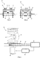
- FIG.1 shows a first embodiment of a movement sensor 10.
- a slider 12 is mounted displaceably in the longitudinal direction L, for example by means of slide bearings.
- the bearings can be provided in coaxial openings on two opposing holding arms of the guide 11, which are perpendicular to the longitudinal direction L, as in FIG FIG.1 indicated.
- two pickups 13, 14 are attached to the guide 11 at a predetermined longitudinal distance.
- a trigger element 15, for example a permanent magnet, which interacts with the sensors 13, 14, is arranged approximately in the center of the slide 12.
- the sensors 13, 14 can be designed as non-contact proximity switches, such as reed contacts or the like.
- the slider 12 When a consumer attached to the guide 11 moves away, the slider 12 is moved backwards relative to the guide 11 (to the left in FIG.1 ), ie the first pickup 13 will then respond. When the slider 12 moves forward relative to the guide (to the right in FIG.1 ) moves, the second pickup 14 will respond. In this way, the direction of movement can be identified in a robust and particularly simple manner, since the output signal of the transducers 13, 14 depends on the relative position of the floating slider 12 relative to the guide 11. It is irrelevant here whether the guide 11 at the connection point on the consumer side and the slider 12 at the corresponding movable end of a line routing device (cf. FIG.3-4 ) is attached or vice versa, only the behavior of the transducers 13, 14 will be reversed accordingly.
- FIG.1 shows, in addition to the transducers 13, 14, two limit switches 16, 17 at opposite ends of the guide 11, right next to the holding arms.
- the limit switches 16, 17 act in the same way The same principle as the transducers, however, indicate that a maximum desired longitudinal displacement has been reached, according to which the distance between the limit switches 16, 17 and thus the motion sensor 10 is to be dimensioned.
- FIG. 11 shows a second exemplary embodiment of a motion sensor 20, which is essentially only in two aspects FIG.1 differs.
- the pickups 23, 24 for direction recognition are not attached to the guide 21 here, but to the slider 22. Accordingly, two release elements 15 are provided on the guide 21 at the end regions.
- the mode of operation of the sensors 23, 24, however, is identical to that of the sensors 13, 14.
- the movement sensor 20 has end stops 28, 29, for example cross bolts, which engage the holding arms. The end stops 28, 29 limit the relative movement of the slider 22 in relation to the guide 21 and are, if necessary, made sufficiently strong to use the movement sensor 20 as a driver with a floating bearing in the longitudinal direction L at the same time.
- FIG.3 shows a device 30 for the horizontal winding and unwinding of an energy chain 31 for the protected guidance of lines, cables, hoses or the like (in FIG.3 Not shown).
- the device 30 comprises a rotatably mounted drum 32 for winding and unwinding the energy guiding chain 31 with a corresponding drum drive 38 for driving the drum.
- the device has a special spiral belt 33 which connects the non-extendable end of the energy guiding chain 31 to the fixed point.
- the device 30 is essentially in accordance with DE 10 2012 110 967 A1 executed.
- a sensor unit 35 is provided on the extendable and retractable or consumer-side end region of the energy guiding chain 31, which has a motion sensor 10 or 20 according to FIG FIG.1 or FIG.2 includes to detect a movement variable, in particular the direction of movement of the consumer (not shown in FIG FIG.3 ).
- a control unit 36 which is connected to the sensor unit 35 and the drum drive 38 for signaling purposes, is used for actuation of the drum drive 38 according to the detected movement size.
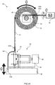
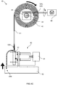
- FIGS. 4A-4C show a device 40 for vertically winding and unwinding an energy chain 51, for the protected guidance of supply lines 54, for example for a civil engineering tool, between a first connection point 53A and a second connection point 53B on a consumer 50, which is movable relative to this similar principle as the device 30 from FIG.3 and in particular comprises a sensor unit 45 with a motion sensor 10 according to FIG FIG.1 , wherein the guide is fixedly attached to the consumer 50 and the slider is fixedly attached to the movable end region 52B of the energy guiding chain 51.
- the arrangement can also be reversed.
- the device 40 according to FIGS. 4A-4C has an electric motor 48 as a drive to support the upward and / or retracting movement of the energy guiding chain 51 or to drive the rotatable drum 42.
- the sensor unit 35 uses the movement sensor 10 to detect the direction of movement of the consumer 50 FIG.4B or.
- FIG.4C with hibernation in FIG.4A shows, one sensor 13 will respond when the consumer 50 moves downwards and the other sensor 14 will respond when the consumer 50 moves upwards.
- the control unit 46 controls the drum drive 48 via the signal line 55 in order to wind up the energy guiding chain 31 ( FIG.4C ) or unwind ( FIG.4B ). Due to the design of the movement sensor 10, the energy guiding chain 31 will essentially be able to follow the movement of the consumer. Should a breakdown occur, for example a jamming of the energy chain 31, the control unit 46 can recognize this using the limit switches 16, 17 and, if necessary, trigger an emergency stop of the consumer 50, for example by stopping a cable winch for the civil engineering
- FIGS. 4A-4C also show a self-locking worm gear connected on the drive side to the drum drive 48, which drives the drum axis 44, ie the shaft of the drum 42, on the output side. This prevents uncontrolled freewheeling.
- control unit 46 can also be arranged at the drum drive 48, ie on the stationary side of the energy chain 31.
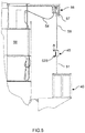
- FIG.5 shows a further application example of the device 40, for example according to FIGS. 4A-4C , for the power supply of a seaworthy ship 50 as a consumer.
- the device 40 (not shown here) is provided in a standard container, which is shown in FIG.5 is set up, for example, directly on the quay wall of a port.
- the ship 50 has a boom arm with a cable winch 56, with steel cable 58 and crane hook (not shown) for raising and lowering a combined coupling and sensor unit 45 of the device 40.
- FIGS. 4A-4C a coupling device 57, for example for a plug connection, is arranged on the boom of the ship 50 near the cable winch 56.
- the end portion 52B of the power chain 51 is how to FIGS. 4A-4C explained, mounted in a floating manner within the coupling and sensor unit 45 and equipped with a motion sensor (cf. FIGS. 4A-4C ) functionally connected.
- the mode of action according to the arrangement FIG.5 is with respect to the forces correspondingly reversed than to FIGS. 4A-4C described, the drum drive following the drive of the cable winch 56 here as well.
- the structure of the device 40 is adapted to the opposite force relationships, otherwise analogous to FIGS. 4A-4C described. If the combined coupling and sensor unit 45 is pulled up by the cable winch 56, the drum drive of the device 40 switches on and extends the energy guiding chain 51 until it engages on the coupling device 57 of the ship 50 and connects to the supply lines 54. At this point in time, the cable winch 56 stops, which causes the drum drive to be switched off. The uncoupling, retraction and winding up of the energy chain 51 in the container of the device 40 is reversed accordingly, with the energy chain 51 being automatically wound onto the drum ( FIGS. 4A-4C ).
- the device 40 can also on the ship 50, in particular a Container ship, be arranged itself, the motor-supported and sensor-controlled device 40 being used for extending and retracting the energy guiding chain 51 from the ship to the landing stage, with the mode of action and structure identical to that of FIG.3 or FIGS. 4A-4C described.
- Typical power consumption for shore power supply for example from container or cruise ships, is in the range of a few megawatts (MW) for three phases. Therefore, suitable supply lines are extremely heavy.
- the motor-supported and sensor-controlled arrangement for routing lines can thus be used particularly advantageously for shore power supply.
Landscapes
- Engineering & Computer Science (AREA)
- General Engineering & Computer Science (AREA)
- Mechanical Engineering (AREA)
- Storing, Repeated Paying-Out, And Re-Storing Of Elongated Articles (AREA)
- Measurement Of Length, Angles, Or The Like Using Electric Or Magnetic Means (AREA)
- Electric Cable Arrangement Between Relatively Moving Parts (AREA)
- Devices For Conveying Motion By Means Of Endless Flexible Members (AREA)
Priority Applications (1)
| Application Number | Priority Date | Filing Date | Title |
|---|---|---|---|
| PL16702145T PL3253992T3 (pl) | 2015-02-02 | 2016-02-01 | Urządzenie do prowadzenia przewodu z czujnikiem ruchu oraz układ napędowy i urządzenie nawijające z takim urządzeniem do prowadzenia przewodu |
Applications Claiming Priority (2)
| Application Number | Priority Date | Filing Date | Title |
|---|---|---|---|
| DE202015100484.2U DE202015100484U1 (de) | 2015-02-02 | 2015-02-02 | Leitungsführungseinrichtung mit einem Bewegungssensor, sowie Antriebsanordnung und Wickelvorrichtung mit einer solchen Leitungsführungseinrichtung |
| PCT/EP2016/052074 WO2016124546A1 (de) | 2015-02-02 | 2016-02-01 | Leitungsführungseinrichtung mit einem bewegungssensor, sowie antriebsanordnung und wickelvorrichtung mit einer solchen leitungsführungseinrichtung |
Publications (2)
| Publication Number | Publication Date |
|---|---|
| EP3253992A1 EP3253992A1 (de) | 2017-12-13 |
| EP3253992B1 true EP3253992B1 (de) | 2022-01-05 |
Family
ID=55272499
Family Applications (1)
| Application Number | Title | Priority Date | Filing Date |
|---|---|---|---|
| EP16702145.0A Active EP3253992B1 (de) | 2015-02-02 | 2016-02-01 | Leitungsführungseinrichtung mit einem bewegungssensor, sowie antriebsanordnung und wickelvorrichtung mit einer solchen leitungsführungseinrichtung |
Country Status (10)
| Country | Link |
|---|---|
| US (1) | US10862290B2 (es) |
| EP (1) | EP3253992B1 (es) |
| JP (1) | JP6706265B2 (es) |
| KR (1) | KR102600763B1 (es) |
| CN (1) | CN107431345B (es) |
| DE (1) | DE202015100484U1 (es) |
| ES (1) | ES2908420T3 (es) |
| PL (1) | PL3253992T3 (es) |
| TW (1) | TWI691662B (es) |
| WO (1) | WO2016124546A1 (es) |
Families Citing this family (7)
| Publication number | Priority date | Publication date | Assignee | Title |
|---|---|---|---|---|
| DE202016105840U1 (de) | 2016-10-18 | 2017-11-23 | Igus Gmbh | Schnelllauf-Hubvorrichtung mit Versorgungsleitung und Energieführungskette hierfür |
| DE202016107317U1 (de) | 2016-12-23 | 2017-03-27 | Igus Gmbh | Systeme zur Überwachung des Betriebs einer Energieführungskette |
| CN106885808A (zh) * | 2017-03-03 | 2017-06-23 | 核动力运行研究所 | 一种微型可升降式视频检查装置 |
| CN106939957A (zh) * | 2017-03-03 | 2017-07-11 | 核动力运行研究所 | 一种支吊架视频检查装置 |
| DE202018106543U1 (de) * | 2018-11-19 | 2019-12-20 | Igus Gmbh | System zur Leitungsüberwachung in einer Leitungsführungseinrichtung, insbesondere in einer Energieführungskette |
| AT521489B1 (de) * | 2018-12-13 | 2020-02-15 | Trumpf Maschinen Austria Gmbh & Co Kg | Werkzeug-Transfervorrichtung |
| KR102100637B1 (ko) * | 2019-12-19 | 2020-04-14 | 주식회사 아소아 | 릴 구동 제어장치가 구비된 어라운드 뷰 장치 |
Family Cites Families (17)
| Publication number | Priority date | Publication date | Assignee | Title |
|---|---|---|---|---|
| DE1250231B (es) * | 1967-09-14 | |||
| DE1117190B (de) * | 1960-10-03 | 1961-11-16 | Horst Broziat | Wicklungsverteiler fuer wechselnde Vorschubrichtung bei gleicher Antriebsrichtung, insbesondere fuer Seil- und Kabelhaspeln |
| DE2410835A1 (de) * | 1974-03-07 | 1975-09-11 | Lotz Kg Gastechnik | Laengenmesseinrichtung, insbesondere fuer metall-strangguss |
| DE4119211C1 (es) | 1991-06-11 | 1992-12-17 | Bauer Spezialtiefbau Gmbh, 8898 Schrobenhausen, De | |
| US6057682A (en) * | 1998-04-17 | 2000-05-02 | Cts Corporation | Dual rotational and linear position sensor |
| DE20305619U1 (de) * | 2003-04-04 | 2003-08-14 | Igus Gmbh | Überwachungssystem für Energieführungskette |
| DE10333834A1 (de) * | 2003-07-24 | 2005-08-11 | Igus Spritzgussteile für die Industrie GmbH | Schiebetürensystem |
| DE202008001415U1 (de) | 2008-01-31 | 2009-06-04 | Kabelschlepp Gmbh | System mit Sicherheitsabschaltung |
| DE102009035091A1 (de) * | 2009-07-28 | 2011-02-10 | Mahle International Gmbh | Positionssensor und Linearaktuator |
| DE202011107804U1 (de) * | 2011-11-14 | 2011-12-16 | Igus Gmbh | Leitungsführungssystem |
| DE202012001760U1 (de) * | 2012-02-23 | 2012-05-30 | Igus Gmbh | Kabelführung |
| DE102012113082A1 (de) | 2012-12-24 | 2014-06-26 | Tsubaki Kabelschlepp GmbH | Energieführungsvorrichtung mit wenigstens einer Antriebseinrichtung für lange Verfahrwege |
| DE102013201860A1 (de) * | 2013-02-05 | 2014-08-07 | Terex Cranes Germany Gmbh | Verfahren zur Beeinflussung einer auf einen Seiltrieb wirkenden Seilwindenkraft und Vorrichtung zur Durchführung eines derartigen Verfahrens |
| DE202013101203U1 (de) * | 2013-03-20 | 2013-03-26 | Igus Gmbh | Energieführungskette insbesondere für Reinraumanwendungen |
| DE202013101457U1 (de) * | 2013-04-05 | 2013-04-19 | Igus Gmbh | Energieführungskette |
| DE102013105223A1 (de) * | 2013-05-22 | 2014-11-27 | Dr. Ing. H.C. F. Porsche Aktiengesellschaft | Luftleitvorrichtung für ein Fahrzeug |
| DE202014100540U1 (de) * | 2014-02-07 | 2014-03-20 | Igus Gmbh | Energieführungskette und Überwachungssystem zum Schutz gegen Leitungsabriss |
-
2015
- 2015-02-02 DE DE202015100484.2U patent/DE202015100484U1/de active Active
-
2016
- 2016-01-29 TW TW105102775A patent/TWI691662B/zh active
- 2016-02-01 EP EP16702145.0A patent/EP3253992B1/de active Active
- 2016-02-01 CN CN201680014360.4A patent/CN107431345B/zh active Active
- 2016-02-01 ES ES16702145T patent/ES2908420T3/es active Active
- 2016-02-01 WO PCT/EP2016/052074 patent/WO2016124546A1/de active Application Filing
- 2016-02-01 KR KR1020177023368A patent/KR102600763B1/ko active IP Right Grant
- 2016-02-01 JP JP2017539325A patent/JP6706265B2/ja active Active
- 2016-02-01 US US15/548,316 patent/US10862290B2/en active Active
- 2016-02-01 PL PL16702145T patent/PL3253992T3/pl unknown
Also Published As
| Publication number | Publication date |
|---|---|
| US10862290B2 (en) | 2020-12-08 |
| KR20170109591A (ko) | 2017-09-29 |
| CN107431345B (zh) | 2021-08-13 |
| US20180026432A1 (en) | 2018-01-25 |
| TWI691662B (zh) | 2020-04-21 |
| KR102600763B1 (ko) | 2023-11-10 |
| JP2018512540A (ja) | 2018-05-17 |
| ES2908420T3 (es) | 2022-04-29 |
| PL3253992T3 (pl) | 2022-05-30 |
| WO2016124546A1 (de) | 2016-08-11 |
| TW201636520A (zh) | 2016-10-16 |
| JP6706265B2 (ja) | 2020-06-03 |
| EP3253992A1 (de) | 2017-12-13 |
| CN107431345A (zh) | 2017-12-01 |
| DE202015100484U1 (de) | 2016-03-03 |
Similar Documents
| Publication | Publication Date | Title |
|---|---|---|
| EP3253992B1 (de) | Leitungsführungseinrichtung mit einem bewegungssensor, sowie antriebsanordnung und wickelvorrichtung mit einer solchen leitungsführungseinrichtung | |
| EP3424871A2 (de) | Seilwindenanordnung | |
| DE102010020016A1 (de) | Kran und Verfahren zum Aufrichten des Krans | |
| DE2457864C2 (de) | Laufkatzenkran | |
| DE4204153C2 (de) | Winde | |
| EP1914365A2 (de) | Sonnen-oder Regenschutzanlage | |
| EP2444585A2 (de) | Verfahren zur Überwachung von Bewegungen an einem Rolltor sowie Vorrichtung zur Durchführung des Verfahrens | |
| WO2014044391A1 (de) | Verfahren zum betrieb eines krans und kran | |
| EP2730738A1 (de) | Wickelvorrichtung zur Abdeckung von Öffnungen in Wandabschnitten | |
| EP3228492A1 (de) | Energiezuführung für eine umschlagmaschine | |
| DE19933771B4 (de) | Kran | |
| DE102004061182A1 (de) | Scherenhubtisch | |
| EP2402281A1 (de) | Verfahren zum Betrieb eines Turmdrehkranes | |
| EP2889431B1 (de) | Arbeitsmaschine für den Schürfkübelbetrieb | |
| DE19825312B4 (de) | System zum Steuern der Bewegungen einer Lasthebevorrichtung | |
| DE202009013349U1 (de) | Lasthebeeinrichtung und Steuereinrichtung hierfür | |
| DE918320C (de) | Bagger, Kran oder aehnliches Geraet mit ausziehbarem Ausleger | |
| EP3645913A1 (de) | Anordnung mit zwei energieführungsketten und verstellbarem festpunkt | |
| EP2179957B1 (de) | Schrägaufzug und Verfahren zu dessen Steuerung | |
| EP1543744A1 (de) | Hubvorrichtung für Betten | |
| EP1181963A1 (de) | Vorrichtung und Verfahren zum Betätigen eines Handkonterzugs im Bühnenbereich | |
| EP4008875A1 (de) | Raffstore und verfahren zum modifizieren eines raffstores | |
| DE3025130A1 (de) | Transportabler punktzug fuer einen buehnenhaus-schnuerboden | |
| AT233769B (de) | Laufkatze | |
| DE102021131264A1 (de) | Vorrichtung und Verfahren zur Vermeidung einer Aufweitung der Wicklungen eines Zugmittels bei Lastwechsel |
Legal Events
| Date | Code | Title | Description |
|---|---|---|---|
| STAA | Information on the status of an ep patent application or granted ep patent |
Free format text: STATUS: THE INTERNATIONAL PUBLICATION HAS BEEN MADE |
|
| PUAI | Public reference made under article 153(3) epc to a published international application that has entered the european phase |
Free format text: ORIGINAL CODE: 0009012 |
|
| STAA | Information on the status of an ep patent application or granted ep patent |
Free format text: STATUS: REQUEST FOR EXAMINATION WAS MADE |
|
| 17P | Request for examination filed |
Effective date: 20170830 |
|
| AK | Designated contracting states |
Kind code of ref document: A1 Designated state(s): AL AT BE BG CH CY CZ DE DK EE ES FI FR GB GR HR HU IE IS IT LI LT LU LV MC MK MT NL NO PL PT RO RS SE SI SK SM TR |
|
| AX | Request for extension of the european patent |
Extension state: BA ME |
|
| DAV | Request for validation of the european patent (deleted) | ||
| DAX | Request for extension of the european patent (deleted) | ||
| STAA | Information on the status of an ep patent application or granted ep patent |
Free format text: STATUS: EXAMINATION IS IN PROGRESS |
|
| 17Q | First examination report despatched |
Effective date: 20200210 |
|
| STAA | Information on the status of an ep patent application or granted ep patent |
Free format text: STATUS: EXAMINATION IS IN PROGRESS |
|
| GRAP | Despatch of communication of intention to grant a patent |
Free format text: ORIGINAL CODE: EPIDOSNIGR1 |
|
| STAA | Information on the status of an ep patent application or granted ep patent |
Free format text: STATUS: GRANT OF PATENT IS INTENDED |
|
| INTG | Intention to grant announced |
Effective date: 20210310 |
|
| GRAJ | Information related to disapproval of communication of intention to grant by the applicant or resumption of examination proceedings by the epo deleted |
Free format text: ORIGINAL CODE: EPIDOSDIGR1 |
|
| STAA | Information on the status of an ep patent application or granted ep patent |
Free format text: STATUS: EXAMINATION IS IN PROGRESS |
|
| INTC | Intention to grant announced (deleted) | ||
| GRAP | Despatch of communication of intention to grant a patent |
Free format text: ORIGINAL CODE: EPIDOSNIGR1 |
|
| STAA | Information on the status of an ep patent application or granted ep patent |
Free format text: STATUS: GRANT OF PATENT IS INTENDED |
|
| INTG | Intention to grant announced |
Effective date: 20210917 |
|
| GRAS | Grant fee paid |
Free format text: ORIGINAL CODE: EPIDOSNIGR3 |
|
| GRAA | (expected) grant |
Free format text: ORIGINAL CODE: 0009210 |
|
| STAA | Information on the status of an ep patent application or granted ep patent |
Free format text: STATUS: THE PATENT HAS BEEN GRANTED |
|
| AK | Designated contracting states |
Kind code of ref document: B1 Designated state(s): AL AT BE BG CH CY CZ DE DK EE ES FI FR GB GR HR HU IE IS IT LI LT LU LV MC MK MT NL NO PL PT RO RS SE SI SK SM TR |
|
| REG | Reference to a national code |
Ref country code: GB Ref legal event code: FG4D Free format text: NOT ENGLISH |
|
| REG | Reference to a national code |
Ref country code: CH Ref legal event code: EP |
|
| REG | Reference to a national code |
Ref country code: AT Ref legal event code: REF Ref document number: 1460862 Country of ref document: AT Kind code of ref document: T Effective date: 20220115 |
|
| REG | Reference to a national code |
Ref country code: DE Ref legal event code: R096 Ref document number: 502016014342 Country of ref document: DE |
|
| REG | Reference to a national code |
Ref country code: IE Ref legal event code: FG4D Free format text: LANGUAGE OF EP DOCUMENT: GERMAN |
|
| REG | Reference to a national code |
Ref country code: NL Ref legal event code: FP |
|
| REG | Reference to a national code |
Ref country code: LT Ref legal event code: MG9D |
|
| REG | Reference to a national code |
Ref country code: ES Ref legal event code: FG2A Ref document number: 2908420 Country of ref document: ES Kind code of ref document: T3 Effective date: 20220429 |
|
| PG25 | Lapsed in a contracting state [announced via postgrant information from national office to epo] |
Ref country code: SE Free format text: LAPSE BECAUSE OF FAILURE TO SUBMIT A TRANSLATION OF THE DESCRIPTION OR TO PAY THE FEE WITHIN THE PRESCRIBED TIME-LIMIT Effective date: 20220105 Ref country code: RS Free format text: LAPSE BECAUSE OF FAILURE TO SUBMIT A TRANSLATION OF THE DESCRIPTION OR TO PAY THE FEE WITHIN THE PRESCRIBED TIME-LIMIT Effective date: 20220105 Ref country code: PT Free format text: LAPSE BECAUSE OF FAILURE TO SUBMIT A TRANSLATION OF THE DESCRIPTION OR TO PAY THE FEE WITHIN THE PRESCRIBED TIME-LIMIT Effective date: 20220505 Ref country code: NO Free format text: LAPSE BECAUSE OF FAILURE TO SUBMIT A TRANSLATION OF THE DESCRIPTION OR TO PAY THE FEE WITHIN THE PRESCRIBED TIME-LIMIT Effective date: 20220405 Ref country code: LT Free format text: LAPSE BECAUSE OF FAILURE TO SUBMIT A TRANSLATION OF THE DESCRIPTION OR TO PAY THE FEE WITHIN THE PRESCRIBED TIME-LIMIT Effective date: 20220105 Ref country code: HR Free format text: LAPSE BECAUSE OF FAILURE TO SUBMIT A TRANSLATION OF THE DESCRIPTION OR TO PAY THE FEE WITHIN THE PRESCRIBED TIME-LIMIT Effective date: 20220105 Ref country code: BG Free format text: LAPSE BECAUSE OF FAILURE TO SUBMIT A TRANSLATION OF THE DESCRIPTION OR TO PAY THE FEE WITHIN THE PRESCRIBED TIME-LIMIT Effective date: 20220405 |
|
| PG25 | Lapsed in a contracting state [announced via postgrant information from national office to epo] |
Ref country code: LV Free format text: LAPSE BECAUSE OF FAILURE TO SUBMIT A TRANSLATION OF THE DESCRIPTION OR TO PAY THE FEE WITHIN THE PRESCRIBED TIME-LIMIT Effective date: 20220105 Ref country code: GR Free format text: LAPSE BECAUSE OF FAILURE TO SUBMIT A TRANSLATION OF THE DESCRIPTION OR TO PAY THE FEE WITHIN THE PRESCRIBED TIME-LIMIT Effective date: 20220406 Ref country code: FI Free format text: LAPSE BECAUSE OF FAILURE TO SUBMIT A TRANSLATION OF THE DESCRIPTION OR TO PAY THE FEE WITHIN THE PRESCRIBED TIME-LIMIT Effective date: 20220105 |
|
| PG25 | Lapsed in a contracting state [announced via postgrant information from national office to epo] |
Ref country code: IS Free format text: LAPSE BECAUSE OF FAILURE TO SUBMIT A TRANSLATION OF THE DESCRIPTION OR TO PAY THE FEE WITHIN THE PRESCRIBED TIME-LIMIT Effective date: 20220505 |
|
| REG | Reference to a national code |
Ref country code: DE Ref legal event code: R097 Ref document number: 502016014342 Country of ref document: DE |
|
| REG | Reference to a national code |
Ref country code: BE Ref legal event code: MM Effective date: 20220228 |
|
| PG25 | Lapsed in a contracting state [announced via postgrant information from national office to epo] |
Ref country code: SM Free format text: LAPSE BECAUSE OF FAILURE TO SUBMIT A TRANSLATION OF THE DESCRIPTION OR TO PAY THE FEE WITHIN THE PRESCRIBED TIME-LIMIT Effective date: 20220105 Ref country code: SK Free format text: LAPSE BECAUSE OF FAILURE TO SUBMIT A TRANSLATION OF THE DESCRIPTION OR TO PAY THE FEE WITHIN THE PRESCRIBED TIME-LIMIT Effective date: 20220105 Ref country code: RO Free format text: LAPSE BECAUSE OF FAILURE TO SUBMIT A TRANSLATION OF THE DESCRIPTION OR TO PAY THE FEE WITHIN THE PRESCRIBED TIME-LIMIT Effective date: 20220105 Ref country code: MC Free format text: LAPSE BECAUSE OF FAILURE TO SUBMIT A TRANSLATION OF THE DESCRIPTION OR TO PAY THE FEE WITHIN THE PRESCRIBED TIME-LIMIT Effective date: 20220105 Ref country code: LU Free format text: LAPSE BECAUSE OF NON-PAYMENT OF DUE FEES Effective date: 20220201 Ref country code: EE Free format text: LAPSE BECAUSE OF FAILURE TO SUBMIT A TRANSLATION OF THE DESCRIPTION OR TO PAY THE FEE WITHIN THE PRESCRIBED TIME-LIMIT Effective date: 20220105 Ref country code: DK Free format text: LAPSE BECAUSE OF FAILURE TO SUBMIT A TRANSLATION OF THE DESCRIPTION OR TO PAY THE FEE WITHIN THE PRESCRIBED TIME-LIMIT Effective date: 20220105 Ref country code: CZ Free format text: LAPSE BECAUSE OF FAILURE TO SUBMIT A TRANSLATION OF THE DESCRIPTION OR TO PAY THE FEE WITHIN THE PRESCRIBED TIME-LIMIT Effective date: 20220105 |
|
| PLBE | No opposition filed within time limit |
Free format text: ORIGINAL CODE: 0009261 |
|
| STAA | Information on the status of an ep patent application or granted ep patent |
Free format text: STATUS: NO OPPOSITION FILED WITHIN TIME LIMIT |
|
| PG25 | Lapsed in a contracting state [announced via postgrant information from national office to epo] |
Ref country code: AL Free format text: LAPSE BECAUSE OF FAILURE TO SUBMIT A TRANSLATION OF THE DESCRIPTION OR TO PAY THE FEE WITHIN THE PRESCRIBED TIME-LIMIT Effective date: 20220105 |
|
| 26N | No opposition filed |
Effective date: 20221006 |
|
| PG25 | Lapsed in a contracting state [announced via postgrant information from national office to epo] |
Ref country code: IE Free format text: LAPSE BECAUSE OF NON-PAYMENT OF DUE FEES Effective date: 20220201 |
|
| PG25 | Lapsed in a contracting state [announced via postgrant information from national office to epo] |
Ref country code: SI Free format text: LAPSE BECAUSE OF FAILURE TO SUBMIT A TRANSLATION OF THE DESCRIPTION OR TO PAY THE FEE WITHIN THE PRESCRIBED TIME-LIMIT Effective date: 20220105 Ref country code: BE Free format text: LAPSE BECAUSE OF NON-PAYMENT OF DUE FEES Effective date: 20220228 |
|
| PGFP | Annual fee paid to national office [announced via postgrant information from national office to epo] |
Ref country code: FR Payment date: 20230217 Year of fee payment: 8 |
|
| PGFP | Annual fee paid to national office [announced via postgrant information from national office to epo] |
Ref country code: PL Payment date: 20230120 Year of fee payment: 8 Ref country code: IT Payment date: 20230228 Year of fee payment: 8 |
|
| P01 | Opt-out of the competence of the unified patent court (upc) registered |
Effective date: 20230526 |
|
| PGFP | Annual fee paid to national office [announced via postgrant information from national office to epo] |
Ref country code: DE Payment date: 20230426 Year of fee payment: 8 |
|
| PG25 | Lapsed in a contracting state [announced via postgrant information from national office to epo] |
Ref country code: HU Free format text: LAPSE BECAUSE OF FAILURE TO SUBMIT A TRANSLATION OF THE DESCRIPTION OR TO PAY THE FEE WITHIN THE PRESCRIBED TIME-LIMIT; INVALID AB INITIO Effective date: 20160201 |
|
| PGFP | Annual fee paid to national office [announced via postgrant information from national office to epo] |
Ref country code: NL Payment date: 20240220 Year of fee payment: 9 Ref country code: ES Payment date: 20240319 Year of fee payment: 9 |
|
| PGFP | Annual fee paid to national office [announced via postgrant information from national office to epo] |
Ref country code: AT Payment date: 20240216 Year of fee payment: 9 |
|
| PG25 | Lapsed in a contracting state [announced via postgrant information from national office to epo] |
Ref country code: MK Free format text: LAPSE BECAUSE OF FAILURE TO SUBMIT A TRANSLATION OF THE DESCRIPTION OR TO PAY THE FEE WITHIN THE PRESCRIBED TIME-LIMIT Effective date: 20220105 Ref country code: CY Free format text: LAPSE BECAUSE OF FAILURE TO SUBMIT A TRANSLATION OF THE DESCRIPTION OR TO PAY THE FEE WITHIN THE PRESCRIBED TIME-LIMIT Effective date: 20220105 |
|
| PGFP | Annual fee paid to national office [announced via postgrant information from national office to epo] |
Ref country code: GB Payment date: 20240222 Year of fee payment: 9 Ref country code: CH Payment date: 20240301 Year of fee payment: 9 |