JP6706265B2 - 動作センサを有するライン誘導デバイス、ならびに当該ライン誘導デバイスを有する駆動機構および巻取り装置 - Google Patents
動作センサを有するライン誘導デバイス、ならびに当該ライン誘導デバイスを有する駆動機構および巻取り装置 Download PDFInfo
- Publication number
- JP6706265B2 JP6706265B2 JP2017539325A JP2017539325A JP6706265B2 JP 6706265 B2 JP6706265 B2 JP 6706265B2 JP 2017539325 A JP2017539325 A JP 2017539325A JP 2017539325 A JP2017539325 A JP 2017539325A JP 6706265 B2 JP6706265 B2 JP 6706265B2
- Authority
- JP
- Japan
- Prior art keywords
- line
- motion sensor
- guide
- chain
- drive
- Prior art date
- Legal status (The legal status is an assumption and is not a legal conclusion. Google has not performed a legal analysis and makes no representation as to the accuracy of the status listed.)
- Active
Links
- 230000033001 locomotion Effects 0.000 title claims description 77
- 238000004804 winding Methods 0.000 title claims description 24
- 230000007246 mechanism Effects 0.000 title claims description 23
- 230000006698 induction Effects 0.000 claims description 30
- 238000006073 displacement reaction Methods 0.000 claims description 10
- 230000005540 biological transmission Effects 0.000 claims description 6
- 230000001681 protective effect Effects 0.000 claims description 4
- 230000008878 coupling Effects 0.000 description 8
- 238000010168 coupling process Methods 0.000 description 8
- 238000005859 coupling reaction Methods 0.000 description 8
- 238000007667 floating Methods 0.000 description 4
- 238000000034 method Methods 0.000 description 4
- 230000033228 biological regulation Effects 0.000 description 3
- 238000005516 engineering process Methods 0.000 description 3
- 235000014676 Phragmites communis Nutrition 0.000 description 2
- 230000004888 barrier function Effects 0.000 description 2
- 238000004891 communication Methods 0.000 description 2
- 238000010276 construction Methods 0.000 description 2
- 238000001514 detection method Methods 0.000 description 2
- 230000005291 magnetic effect Effects 0.000 description 2
- 230000009467 reduction Effects 0.000 description 2
- 230000001360 synchronised effect Effects 0.000 description 2
- 229910000831 Steel Inorganic materials 0.000 description 1
- 230000008859 change Effects 0.000 description 1
- 230000001066 destructive effect Effects 0.000 description 1
- 238000010586 diagram Methods 0.000 description 1
- 238000005553 drilling Methods 0.000 description 1
- 230000005294 ferromagnetic effect Effects 0.000 description 1
- 230000001939 inductive effect Effects 0.000 description 1
- 238000005259 measurement Methods 0.000 description 1
- 230000003287 optical effect Effects 0.000 description 1
- 238000010248 power generation Methods 0.000 description 1
- 239000010959 steel Substances 0.000 description 1
Images


Classifications
-
- F—MECHANICAL ENGINEERING; LIGHTING; HEATING; WEAPONS; BLASTING
- F16—ENGINEERING ELEMENTS AND UNITS; GENERAL MEASURES FOR PRODUCING AND MAINTAINING EFFECTIVE FUNCTIONING OF MACHINES OR INSTALLATIONS; THERMAL INSULATION IN GENERAL
- F16G—BELTS, CABLES, OR ROPES, PREDOMINANTLY USED FOR DRIVING PURPOSES; CHAINS; FITTINGS PREDOMINANTLY USED THEREFOR
- F16G13/00—Chains
- F16G13/12—Hauling- or hoisting-chains so called ornamental chains
- F16G13/16—Hauling- or hoisting-chains so called ornamental chains with arrangements for holding electric cables, hoses, or the like
-
- H—ELECTRICITY
- H02—GENERATION; CONVERSION OR DISTRIBUTION OF ELECTRIC POWER
- H02G—INSTALLATION OF ELECTRIC CABLES OR LINES, OR OF COMBINED OPTICAL AND ELECTRIC CABLES OR LINES
- H02G11/00—Arrangements of electric cables or lines between relatively-movable parts
- H02G11/02—Arrangements of electric cables or lines between relatively-movable parts using take-up reel or drum
-
- B—PERFORMING OPERATIONS; TRANSPORTING
- B65—CONVEYING; PACKING; STORING; HANDLING THIN OR FILAMENTARY MATERIAL
- B65H—HANDLING THIN OR FILAMENTARY MATERIAL, e.g. SHEETS, WEBS, CABLES
- B65H75/00—Storing webs, tapes, or filamentary material, e.g. on reels
- B65H75/02—Cores, formers, supports, or holders for coiled, wound, or folded material, e.g. reels, spindles, bobbins, cop tubes, cans, mandrels or chucks
- B65H75/34—Cores, formers, supports, or holders for coiled, wound, or folded material, e.g. reels, spindles, bobbins, cop tubes, cans, mandrels or chucks specially adapted or mounted for storing and repeatedly paying-out and re-storing lengths of material provided for particular purposes, e.g. anchored hoses, power cables
- B65H75/38—Cores, formers, supports, or holders for coiled, wound, or folded material, e.g. reels, spindles, bobbins, cop tubes, cans, mandrels or chucks specially adapted or mounted for storing and repeatedly paying-out and re-storing lengths of material provided for particular purposes, e.g. anchored hoses, power cables involving the use of a core or former internal to, and supporting, a stored package of material
- B65H75/44—Constructional details
- B65H75/4481—Arrangements or adaptations for driving the reel or the material
- B65H75/4486—Electric motors
-
- B—PERFORMING OPERATIONS; TRANSPORTING
- B65—CONVEYING; PACKING; STORING; HANDLING THIN OR FILAMENTARY MATERIAL
- B65H—HANDLING THIN OR FILAMENTARY MATERIAL, e.g. SHEETS, WEBS, CABLES
- B65H2403/00—Power transmission; Driving means
- B65H2403/40—Toothed gearings
- B65H2403/46—Toothed gearings worm gearing
-
- H—ELECTRICITY
- H02—GENERATION; CONVERSION OR DISTRIBUTION OF ELECTRIC POWER
- H02G—INSTALLATION OF ELECTRIC CABLES OR LINES, OR OF COMBINED OPTICAL AND ELECTRIC CABLES OR LINES
- H02G11/00—Arrangements of electric cables or lines between relatively-movable parts
- H02G11/006—Arrangements of electric cables or lines between relatively-movable parts using extensible carrier for the cable, e.g. self-coiling spring
Landscapes
- Engineering & Computer Science (AREA)
- General Engineering & Computer Science (AREA)
- Mechanical Engineering (AREA)
- Storing, Repeated Paying-Out, And Re-Storing Of Elongated Articles (AREA)
- Measurement Of Length, Angles, Or The Like Using Electric Or Magnetic Means (AREA)
- Electric Cable Arrangement Between Relatively Moving Parts (AREA)
- Devices For Conveying Motion By Means Of Endless Flexible Members (AREA)
Description
ライン誘導デバイスは動作センサならびに駆動機構を有し、巻取り装置はそのようなラインガイドデバイスを有する。
10 動作センサ
11 ガイド
12 スライダ
13 第1のピックアップ
14 第2のピックアップ
15 トリガ素子
16、17 リミット・スイッチ
L 長手方向
図2
20 動作センサ
21 ガイド
22 スライダ
23 第1のピックアップ
24 第2のピックアップ
25 トリガ素子
28、29 端部アバットメント
L 長手方向
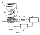
図3
30 巻取り装置
31 エネルギー誘導チェーン
32 ドラム
33 スパイラル・バンド
34 ドラム軸
35 センサ・ユニット
36 制御ユニット
38 電気モータ
図4A〜図4C
10 動作センサ
40 巻取り装置
42 ドラム
44 ドラム軸
45 センサ・ユニット
46 制御ユニット
48 電気モータ
49 ウォーム伝動装置
50 コンシューマ
51 エネルギー誘導チェーン
52A、52B 端部領域
53A、53B 接続位置
54 供給ライン
55 信号ライン
図5
40 巻取り装置
45 連結センサ・ユニット
50 船(コンシューマ)
51 エネルギー誘導チェーン
52B 端部領域
54 供給ライン
56 ケーブル・ウインチ
57 結合デバイス
58 スチール・ケーブル
Claims (15)
- ライン、ケーブル、又はホース(54、55)を、第1の接続位置と前記第1の接続位置に対して相対的に移動可能なコンシューマ上の第2の接続位置との間で保護的に誘導するエネルギー誘導チェーン(31、51)と、
前記エネルギー誘導チェーンの送りおよび/または戻り動作を支援するために前記エネルギー誘導チェーンに動作可能に接続された駆動装置(38、48)と、
前記駆動装置を作動させる制御ユニット(36;46)と、
前記エネルギー誘導チェーンの動作パラメータを検出するセンサ・ユニット(35、45)と、を有し、
前記センサ・ユニットは、コンシューマ側端部領域(52B)の動作パラメータを検出するために、前記エネルギー誘導チェーンの前記コンシューマ側端部領域(52B)に配置された動作センサ(10;20)を有し、
前記動作センサは、前記エネルギー誘導チェーンの送りおよび/または戻り動作を支援するために、前記動作センサ(10;20)によって検出された前記動作パラメータに応じて前記駆動装置(38、48)を作動させる制御ユニット(36;46)に接続されている、ライン誘導機構。 - 前記動作センサ(10;20)が、第1の部品と、前記第1の部品に対して相対的に移動可能な第2の部品とを有する軸受を有し、出力信号が前記第2の部品の前記第1の部品に対する位置に依存する少なくとも1つのピックアップ(13、14;23、24)を含み、
前記動作センサ(10;20)が、ガイド(11;21)と、前記ガイドで長手方向(L)に変位可能なスライダ(12;22)とを有するリニア軸受を有し、出力信号が前記スライダの前記ガイドに対する位置に依存する少なくとも1つのピックアップ(13、14;23、24)を含み、
前記動作センサ(10;20)が、前記コンシューマにある前記第1の部品および対応する移動可能な前記端部領域(52B)にある前記第2の部品と共に、または対応する移動可能な前記端部領域(52B)にある前記第1の部品および前記コンシューマにある前記第2の部品と共に、配置される、請求項1に記載のライン誘導機構。 - 前記少なくとも1つのピックアップ(13、14;23、24)が、前記スライダまたは前記ガイドに取り付けられており、2つのピックアップが、前記長手方向で間隔を空けて設けられている、請求項2に記載のライン誘導機構。
- 前記動作センサ(10)が、前記ガイドまたは前記スライダの相互に対向する端部に、それぞれ長手方向の最大変位が達成されたことを示す2つのリミット・スイッチ(16、17)をさらに有する、請求項2または3に記載のライン誘導機構。
- 前記制御ユニットが、前記制御ユニットによって作動される調整部材としての前記駆動装置(38、48)と、測定部材としての前記動作センサ(10)とを有する閉ループ制御を形成する、請求項1から4のいずれか一項に記載のライン誘導機構。
- 前記動作センサ(10)を前記制御ユニット(46)に接続する信号ライン(55)が、前記エネルギー誘導チェーンを通じて該エネルギー誘導チェーンの固定端部に誘導されている、請求項1から4のいずれか一項に記載のライン誘導機構。
- 前記制御ユニット(36;46)が、前記動作センサが長手方向の最大変位が達成されたことを示す場合に前記移動可能なコンシューマの緊急停止をトリガする、請求項1から6のいずれか一項に記載のライン誘導機構。
- 前記動作センサ(10)が、前記第2の接続位置を前記エネルギー誘導チェーンの移動可能な端部に機械的に結合させ、そのために、前記ガイドまたは前記スライダに、長手方向の最大変位を制限する2つの端部アバットメント(28、29)を有する、請求項2に記載のライン誘導機構。
- 前記エネルギー誘導チェーンが、下方区間、方向変換円弧、および上方区間を形成し、
前記駆動装置が、前記上方区間および/または前記方向変換円弧の送りおよび/または戻り動作を支援し、
前記動作センサ(10;20)が、移動可能な前記端部領域(52B)の動作方向を検出する、請求項1から8のいずれか一項に記載のライン誘導機構。 - ライン、ケーブル、又はホースを、第1の接続位置(53A)と、前記第1の接続位置(53A)に対して相対的に移動可能である、コンシューマ上の第2の接続位置(53B)との間で保護的に誘導するライン誘導デバイス(31;51)と、
前記ライン誘導デバイスを巻取りおよび巻戻す、回転可能に取り付けられたドラム(32;42)と、
前記ドラムを回転させるドラム駆動装置(38;48)と
を含む、ライン誘導デバイスを巻取りおよび巻戻す装置(30;40)であって、
前記ライン誘導デバイスの動作パラメータを検出するために、前記ライン誘導デバイスのコンシューマ側端部領域(52B)に配置されたセンサ・ユニット(35;45)と、
検出された前記動作パラメータに応じて前記ドラム駆動装置を作動させるために、前記センサ・ユニット(35;45)および前記ドラム駆動装置に接続された制御ユニット(36;46)と、を備える装置(30;40)。 - 前記センサ・ユニット(35;45)が、ガイドと、前記ガイドで長手方向(L)に変位可能なスライダと、出力信号が前記スライダの前記ガイドに対する位置に依存する少なくとも1つのピックアップと、を有する動作センサ(10;20)を含む、請求項10に記載の装置。
- 前記制御ユニット(36;46)が、前記ドラム駆動装置(38;48)を回転方向および回転速度に関連して作動させる、請求項10または11に記載の装置。
- 前記ドラム駆動装置が、電気モータ(48)と、駆動側で前記電気モータに接続され、出力側でドラム軸に接続された自動ロック式伝動装置(49)と、を有し、前記伝動装置がウォーム伝動装置(49)である、請求項10から12のいずれか一項に記載の装置。
- 船に陸電を供給するための、請求項10から13のいずれか一項に記載の装置の使用であって、前記ライン誘導デバイスが、陸電供給のために強電流ケーブルを誘導するエネルギー誘導チェーン(51)を含む、使用。
- 垂直に変位可能な地下作業工具を供給するための、請求項10から13のいずれか一項に記載の装置の使用であって、前記第2の接続位置を有する前記地下作業工具が、ウインチのドロー・ケーブルにより運ばれ、ウインチ駆動装置を利用して主として垂直方向で上下に移動し、前記ドラム駆動装置が前記ウインチ駆動装置に追従する、使用。
Applications Claiming Priority (3)
| Application Number | Priority Date | Filing Date | Title |
|---|---|---|---|
| DE202015100484.2 | 2015-02-02 | ||
| DE202015100484.2U DE202015100484U1 (de) | 2015-02-02 | 2015-02-02 | Leitungsführungseinrichtung mit einem Bewegungssensor, sowie Antriebsanordnung und Wickelvorrichtung mit einer solchen Leitungsführungseinrichtung |
| PCT/EP2016/052074 WO2016124546A1 (de) | 2015-02-02 | 2016-02-01 | Leitungsführungseinrichtung mit einem bewegungssensor, sowie antriebsanordnung und wickelvorrichtung mit einer solchen leitungsführungseinrichtung |
Publications (3)
| Publication Number | Publication Date |
|---|---|
| JP2018512540A JP2018512540A (ja) | 2018-05-17 |
| JP2018512540A5 JP2018512540A5 (ja) | 2018-09-06 |
| JP6706265B2 true JP6706265B2 (ja) | 2020-06-03 |
Family
ID=55272499
Family Applications (1)
| Application Number | Title | Priority Date | Filing Date |
|---|---|---|---|
| JP2017539325A Active JP6706265B2 (ja) | 2015-02-02 | 2016-02-01 | 動作センサを有するライン誘導デバイス、ならびに当該ライン誘導デバイスを有する駆動機構および巻取り装置 |
Country Status (10)
| Country | Link |
|---|---|
| US (1) | US10862290B2 (ja) |
| EP (1) | EP3253992B1 (ja) |
| JP (1) | JP6706265B2 (ja) |
| KR (1) | KR102600763B1 (ja) |
| CN (1) | CN107431345B (ja) |
| DE (1) | DE202015100484U1 (ja) |
| ES (1) | ES2908420T3 (ja) |
| PL (1) | PL3253992T3 (ja) |
| TW (1) | TWI691662B (ja) |
| WO (1) | WO2016124546A1 (ja) |
Families Citing this family (7)
| Publication number | Priority date | Publication date | Assignee | Title |
|---|---|---|---|---|
| DE202016105840U1 (de) | 2016-10-18 | 2017-11-23 | Igus Gmbh | Schnelllauf-Hubvorrichtung mit Versorgungsleitung und Energieführungskette hierfür |
| DE202016107317U1 (de) | 2016-12-23 | 2017-03-27 | Igus Gmbh | Systeme zur Überwachung des Betriebs einer Energieführungskette |
| CN106885808A (zh) * | 2017-03-03 | 2017-06-23 | 核动力运行研究所 | 一种微型可升降式视频检查装置 |
| CN106939957A (zh) * | 2017-03-03 | 2017-07-11 | 核动力运行研究所 | 一种支吊架视频检查装置 |
| DE202018106543U1 (de) * | 2018-11-19 | 2019-12-20 | Igus Gmbh | System zur Leitungsüberwachung in einer Leitungsführungseinrichtung, insbesondere in einer Energieführungskette |
| AT521489B1 (de) * | 2018-12-13 | 2020-02-15 | Trumpf Maschinen Austria Gmbh & Co Kg | Werkzeug-Transfervorrichtung |
| KR102100637B1 (ko) * | 2019-12-19 | 2020-04-14 | 주식회사 아소아 | 릴 구동 제어장치가 구비된 어라운드 뷰 장치 |
Family Cites Families (17)
| Publication number | Priority date | Publication date | Assignee | Title |
|---|---|---|---|---|
| DE1250231B (ja) * | 1967-09-14 | |||
| DE1117190B (de) * | 1960-10-03 | 1961-11-16 | Horst Broziat | Wicklungsverteiler fuer wechselnde Vorschubrichtung bei gleicher Antriebsrichtung, insbesondere fuer Seil- und Kabelhaspeln |
| DE2410835A1 (de) * | 1974-03-07 | 1975-09-11 | Lotz Kg Gastechnik | Laengenmesseinrichtung, insbesondere fuer metall-strangguss |
| DE4119211C1 (ja) | 1991-06-11 | 1992-12-17 | Bauer Spezialtiefbau Gmbh, 8898 Schrobenhausen, De | |
| US6057682A (en) * | 1998-04-17 | 2000-05-02 | Cts Corporation | Dual rotational and linear position sensor |
| DE20305619U1 (de) * | 2003-04-04 | 2003-08-14 | Igus Gmbh | Überwachungssystem für Energieführungskette |
| DE10333834A1 (de) * | 2003-07-24 | 2005-08-11 | Igus Spritzgussteile für die Industrie GmbH | Schiebetürensystem |
| DE202008001415U1 (de) | 2008-01-31 | 2009-06-04 | Kabelschlepp Gmbh | System mit Sicherheitsabschaltung |
| DE102009035091A1 (de) * | 2009-07-28 | 2011-02-10 | Mahle International Gmbh | Positionssensor und Linearaktuator |
| DE202011107804U1 (de) * | 2011-11-14 | 2011-12-16 | Igus Gmbh | Leitungsführungssystem |
| DE202012001760U1 (de) * | 2012-02-23 | 2012-05-30 | Igus Gmbh | Kabelführung |
| DE102012113082A1 (de) | 2012-12-24 | 2014-06-26 | Tsubaki Kabelschlepp GmbH | Energieführungsvorrichtung mit wenigstens einer Antriebseinrichtung für lange Verfahrwege |
| DE102013201860A1 (de) * | 2013-02-05 | 2014-08-07 | Terex Cranes Germany Gmbh | Verfahren zur Beeinflussung einer auf einen Seiltrieb wirkenden Seilwindenkraft und Vorrichtung zur Durchführung eines derartigen Verfahrens |
| DE202013101203U1 (de) * | 2013-03-20 | 2013-03-26 | Igus Gmbh | Energieführungskette insbesondere für Reinraumanwendungen |
| DE202013101457U1 (de) * | 2013-04-05 | 2013-04-19 | Igus Gmbh | Energieführungskette |
| DE102013105223A1 (de) * | 2013-05-22 | 2014-11-27 | Dr. Ing. H.C. F. Porsche Aktiengesellschaft | Luftleitvorrichtung für ein Fahrzeug |
| DE202014100540U1 (de) * | 2014-02-07 | 2014-03-20 | Igus Gmbh | Energieführungskette und Überwachungssystem zum Schutz gegen Leitungsabriss |
-
2015
- 2015-02-02 DE DE202015100484.2U patent/DE202015100484U1/de active Active
-
2016
- 2016-01-29 TW TW105102775A patent/TWI691662B/zh active
- 2016-02-01 EP EP16702145.0A patent/EP3253992B1/de active Active
- 2016-02-01 CN CN201680014360.4A patent/CN107431345B/zh active Active
- 2016-02-01 ES ES16702145T patent/ES2908420T3/es active Active
- 2016-02-01 WO PCT/EP2016/052074 patent/WO2016124546A1/de active Application Filing
- 2016-02-01 KR KR1020177023368A patent/KR102600763B1/ko active IP Right Grant
- 2016-02-01 JP JP2017539325A patent/JP6706265B2/ja active Active
- 2016-02-01 US US15/548,316 patent/US10862290B2/en active Active
- 2016-02-01 PL PL16702145T patent/PL3253992T3/pl unknown
Also Published As
| Publication number | Publication date |
|---|---|
| US10862290B2 (en) | 2020-12-08 |
| KR20170109591A (ko) | 2017-09-29 |
| CN107431345B (zh) | 2021-08-13 |
| US20180026432A1 (en) | 2018-01-25 |
| EP3253992B1 (de) | 2022-01-05 |
| TWI691662B (zh) | 2020-04-21 |
| KR102600763B1 (ko) | 2023-11-10 |
| JP2018512540A (ja) | 2018-05-17 |
| ES2908420T3 (es) | 2022-04-29 |
| PL3253992T3 (pl) | 2022-05-30 |
| WO2016124546A1 (de) | 2016-08-11 |
| TW201636520A (zh) | 2016-10-16 |
| EP3253992A1 (de) | 2017-12-13 |
| CN107431345A (zh) | 2017-12-01 |
| DE202015100484U1 (de) | 2016-03-03 |
Similar Documents
| Publication | Publication Date | Title |
|---|---|---|
| JP6706265B2 (ja) | 動作センサを有するライン誘導デバイス、ならびに当該ライン誘導デバイスを有する駆動機構および巻取り装置 | |
| US8959694B2 (en) | Bridge apparatus | |
| JP2018512540A5 (ja) | ||
| KR101832516B1 (ko) | 지지와이어로부터 매달린 화물의 방위를 지지와이어를 중심으로 제어하는 방법과 윈치구조 | |
| EP1235737B1 (en) | Marine heave compensating device and winch drive | |
| KR101651954B1 (ko) | 인버터제어방식 선박동력공급시스템 | |
| CA2461017A1 (en) | System for measuring material properties from a moving construction vehicle | |
| EP2215001B1 (en) | System for dispensing and retrieving a length of cable into/from a cable channel | |
| US8567834B2 (en) | Synchronization of spreader twist-locks in twin lift operations | |
| US20210016861A1 (en) | Automated boat lift and trolley | |
| CN216711456U (zh) | 用于大深度rov收放系统的全自动绞车 | |
| KR20130088405A (ko) | 선박용 접안장치 | |
| KR20090007695U (ko) | 타워 크레인 | |
| KR20190077656A (ko) | 오일펜스용 권선장치 | |
| KR100951715B1 (ko) | 포크레인의 전원공급용 케이블 릴 | |
| CN210802288U (zh) | 一种跳板到码头距离的测量装置 | |
| KR102635602B1 (ko) | Boom 양측면 설치형 캐트너리 트롤리 추락방지장치 | |
| JPS5889582A (ja) | 中折れ式クレーンのロープのサポート装置 | |
| CN116262598A (zh) | 一种用于大深度rov收放系统的全自动绞车 | |
| US20150184357A1 (en) | Work machine for dragline bucket operation | |
| JP2023059646A (ja) | 昇降装置及び衣類処理装置 | |
| JP2007320750A (ja) | 物品移載装置 | |
| JP2023147935A (ja) | 検出装置及びクレーン | |
| JP2002226170A (ja) | ガントリクレーンによるゲート位置換えの自動運転方法 | |
| KR20110118957A (ko) | 스프레더 자동 착지 시스템 |
Legal Events
| Date | Code | Title | Description |
|---|---|---|---|
| A521 | Request for written amendment filed |
Free format text: JAPANESE INTERMEDIATE CODE: A523 Effective date: 20180726 |
|
| A621 | Written request for application examination |
Free format text: JAPANESE INTERMEDIATE CODE: A621 Effective date: 20181207 |
|
| A131 | Notification of reasons for refusal |
Free format text: JAPANESE INTERMEDIATE CODE: A131 Effective date: 20191029 |
|
| A977 | Report on retrieval |
Free format text: JAPANESE INTERMEDIATE CODE: A971007 Effective date: 20191031 |
|
| A521 | Request for written amendment filed |
Free format text: JAPANESE INTERMEDIATE CODE: A523 Effective date: 20200128 |
|
| TRDD | Decision of grant or rejection written | ||
| A01 | Written decision to grant a patent or to grant a registration (utility model) |
Free format text: JAPANESE INTERMEDIATE CODE: A01 Effective date: 20200428 |
|
| A61 | First payment of annual fees (during grant procedure) |
Free format text: JAPANESE INTERMEDIATE CODE: A61 Effective date: 20200515 |
|
| R150 | Certificate of patent or registration of utility model |
Ref document number: 6706265 Country of ref document: JP Free format text: JAPANESE INTERMEDIATE CODE: R150 |
|
| R250 | Receipt of annual fees |
Free format text: JAPANESE INTERMEDIATE CODE: R250 |
|
| R250 | Receipt of annual fees |
Free format text: JAPANESE INTERMEDIATE CODE: R250 |