EP3252941B1 - Wechselrichtersteuerungsvorrichtung und motorantriebssystem - Google Patents
Wechselrichtersteuerungsvorrichtung und motorantriebssystem Download PDFInfo
- Publication number
- EP3252941B1 EP3252941B1 EP16743354.9A EP16743354A EP3252941B1 EP 3252941 B1 EP3252941 B1 EP 3252941B1 EP 16743354 A EP16743354 A EP 16743354A EP 3252941 B1 EP3252941 B1 EP 3252941B1
- Authority
- EP
- European Patent Office
- Prior art keywords
- current command
- current
- command value
- command values
- values
- Prior art date
- Legal status (The legal status is an assumption and is not a legal conclusion. Google has not performed a legal analysis and makes no representation as to the accuracy of the status listed.)
- Active
Links
- 238000010586 diagram Methods 0.000 description 27
- 238000000034 method Methods 0.000 description 10
- 238000004364 calculation method Methods 0.000 description 7
- 230000004907 flux Effects 0.000 description 5
- 230000009466 transformation Effects 0.000 description 5
- 230000001360 synchronised effect Effects 0.000 description 4
- 230000005284 excitation Effects 0.000 description 2
- 230000001419 dependent effect Effects 0.000 description 1
- 230000003993 interaction Effects 0.000 description 1
- 238000004804 winding Methods 0.000 description 1
Images


Classifications
-
- H—ELECTRICITY
- H02—GENERATION; CONVERSION OR DISTRIBUTION OF ELECTRIC POWER
- H02P—CONTROL OR REGULATION OF ELECTRIC MOTORS, ELECTRIC GENERATORS OR DYNAMO-ELECTRIC CONVERTERS; CONTROLLING TRANSFORMERS, REACTORS OR CHOKE COILS
- H02P6/00—Arrangements for controlling synchronous motors or other dynamo-electric motors using electronic commutation dependent on the rotor position; Electronic commutators therefor
- H02P6/14—Electronic commutators
- H02P6/16—Circuit arrangements for detecting position
- H02P6/18—Circuit arrangements for detecting position without separate position detecting elements
- H02P6/182—Circuit arrangements for detecting position without separate position detecting elements using back-emf in windings
-
- H—ELECTRICITY
- H02—GENERATION; CONVERSION OR DISTRIBUTION OF ELECTRIC POWER
- H02P—CONTROL OR REGULATION OF ELECTRIC MOTORS, ELECTRIC GENERATORS OR DYNAMO-ELECTRIC CONVERTERS; CONTROLLING TRANSFORMERS, REACTORS OR CHOKE COILS
- H02P6/00—Arrangements for controlling synchronous motors or other dynamo-electric motors using electronic commutation dependent on the rotor position; Electronic commutators therefor
- H02P6/14—Electronic commutators
- H02P6/16—Circuit arrangements for detecting position
- H02P6/18—Circuit arrangements for detecting position without separate position detecting elements
-
- H—ELECTRICITY
- H02—GENERATION; CONVERSION OR DISTRIBUTION OF ELECTRIC POWER
- H02P—CONTROL OR REGULATION OF ELECTRIC MOTORS, ELECTRIC GENERATORS OR DYNAMO-ELECTRIC CONVERTERS; CONTROLLING TRANSFORMERS, REACTORS OR CHOKE COILS
- H02P21/00—Arrangements or methods for the control of electric machines by vector control, e.g. by control of field orientation
- H02P21/22—Current control, e.g. using a current control loop
-
- H—ELECTRICITY
- H02—GENERATION; CONVERSION OR DISTRIBUTION OF ELECTRIC POWER
- H02P—CONTROL OR REGULATION OF ELECTRIC MOTORS, ELECTRIC GENERATORS OR DYNAMO-ELECTRIC CONVERTERS; CONTROLLING TRANSFORMERS, REACTORS OR CHOKE COILS
- H02P21/00—Arrangements or methods for the control of electric machines by vector control, e.g. by control of field orientation
- H02P21/24—Vector control not involving the use of rotor position or rotor speed sensors
-
- H—ELECTRICITY
- H02—GENERATION; CONVERSION OR DISTRIBUTION OF ELECTRIC POWER
- H02P—CONTROL OR REGULATION OF ELECTRIC MOTORS, ELECTRIC GENERATORS OR DYNAMO-ELECTRIC CONVERTERS; CONTROLLING TRANSFORMERS, REACTORS OR CHOKE COILS
- H02P25/00—Arrangements or methods for the control of AC motors characterised by the kind of AC motor or by structural details
- H02P25/02—Arrangements or methods for the control of AC motors characterised by the kind of AC motor or by structural details characterised by the kind of motor
- H02P25/08—Reluctance motors
Definitions
- Embodiments of the present invention relate to an inverter controller and a motor driving system.
- An inverter controller and a motor driving system capable of estimating, with good accuracy, a rotational phase angle of a motor under a state of high speed and low load, are provided.
- FIG. 1 is a diagram illustrating a configuration of the system according to the present embodiment. As illustrated in Fig. 1 , the system according to the present embodiment includes a motor 1 and an inverter controller 2.
- the motor 1 is a rotary drive target of the controller 2, and is connected to the controller 2.
- the SynRM1 includes a stator and a rotor.
- the stator has three excitation phases (U phase, V phase, and W phase).
- the stator generates a magnetic field with the use of a three-phase alternating current which flows through each excitation phase.
- the rotor does not have a permanent magnet. The rotor is rotated through a magnetic interaction with the magnetic field generated by the stator.
- the inverter controller 2 (which is referred to as “controller 2", hereinafter) controls a rotational phase angle of the SynRM1 in a sensorless manner.
- the controller 2 includes an inverter 21, current detectors 22, a coordinate transformer 23, a current command value calculator 24, a voltage command value calculator 25, a coordinate transformer 26, a PWM modulator 27, and a speed and rotational phase angle estimator 28.
- the inverter 21 is a circuit including switching elements (transistors).
- the inverter 21 switches ON/OFF of the switching elements to convert power from a power source (whose illustration is omitted) into alternating-current power, and supplies it to the SynRM1.
- a control signal for controlling ON/OFF of the respective switching elements is input into the inverter 21 from the PWM modulator 27.
- the current detectors 22 detect current values of two phases or three phases, in the three-phase alternating current flowing through the stator of the SynRM1.
- Fig. 1 illustrates a configuration in which current values iu, iw of two phases (U phase and W phase) are detected.
- the coordinate transformer 23 performs coordinate transformation on the current values iu, iw detected by the current detectors 22, from a three-phase fixed coordinate system to a rotating coordinate system of dc and qc axes.
- the three-phase fixed coordinate system and the rotating coordinate system of dc and qc axes will be described with reference to Fig. 2 .
- the three-phase fixed coordinate system is a fixed coordinate system formed of an ⁇ axis and a ⁇ axis.
- the ⁇ axis is set in the U phase direction
- the ⁇ axis is set in a direction perpendicular to the ⁇ axis.
- the current values iu, iw detected by the current detectors 22 are represented on the three-phase fixed coordinates as described above.
- the rotating coordinate system of dc and qc axes is a rotating coordinate system formed of a dc axis and a qc axis.
- the dc axis is set in a direction which is estimated by the controller 2 as a d axis direction (a direction in which an inductance of the rotor is minimum)
- the qc axis is set in a direction which is estimated by the controller 2 as a q axis direction (a direction in which the inductance of the rotor is maximum).
- An inductance ellipse in Fig. 2 indicates an inductance of the rotor.
- an actual rotational phase angle ⁇ of the rotor is represented by an angle from the ⁇ axis to the d axis.
- an estimated rotational phase angle ⁇ est of the rotor estimated by the controller 2 is represented by an angle from the ⁇ axis to the dc axis. It is indicated that the closer the angle between the rotational phase angle ⁇ and the estimated rotational phase angle ⁇ est, the higher the estimation accuracy of the rotational phase angle.
- the coordinate transformer 23 can transform the three-phase fixed coordinate system into the rotating coordinate system of dc and qc axes, by using the estimated rotational phase angle ⁇ est output by the speed and rotational phase angle estimator 28.
- values obtained when the coordinate transformer 23 performs the coordinate transformation on the current values iu, iw are referred to as current values idc, iqc.
- the current value idc is a dc axis component of the current which flows through the stator
- the current value iqc is a qc axis component of the current which flows through the stator.
- the current command value calculator 24 calculates current command values idc*, iqc*, based on a torque command value T* and an estimated speed ⁇ est.
- the torque command value T* is a value of torque generated in the rotor. In the present embodiment, it is set that the torque command value T* is input from an external device.
- the estimated speed ⁇ est indicates an angular speed of the rotor estimated by the controller 2.
- the current command value idc* is a dc axis component of the current which is flowed through the SynRM1.
- the current command value iqc* is a qc axis component of the current which is flowed through the SynRM1. Details of the current command value calculator 24 will be described later.
- the voltage command value calculator 25 calculates voltage command values vdc*, vqc* with which the current values idc, iqc of the SynRM1 become equal to the current command values idc*, iqc*.
- the voltage command value vdc* is a dc axis component of a voltage applied to the stator of the SynRM1.
- the voltage command value vqc* is a qc axis component of the voltage applied to the stator of the SynRM1.
- the coordinate transformer 26 performs coordinate transformation on the voltage command values vdc*, vqc* output by the voltage command value calculator 25, from the rotating coordinate system of dc and qc axes to the three-phase fixed coordinate system.
- the coordinate transformer 26 can transform the rotating coordinate system of dc and qc axes into the three-phase fixed coordinate system by using the estimated rotational phase angle ⁇ est, in a similar manner to the coordinate transformer 23.
- values obtained when the coordinate transformer 26 performs the coordinate transformation on the voltage command values vdc*, vqc* are referred to as voltage command values vu*, vv*, vw*.
- the voltage command value vu* is a voltage applied to the U phase of the stator
- the voltage command value vv* is a voltage applied to the V phase of the stator
- the voltage command value vw* is a voltage applied to the W phase of the stator.
- the PWM modulator 27 modulates the voltage command values vu*, vv*, vw* through PWM (Pulse-Width Modulation) using a triangular wave, and generates a binary control signal corresponding to ON or OFF of each of the switching elements of the inverter 21.
- the PWM modulator 27 inputs the generated control signal into the inverter 21.
- the speed and rotational phase angle estimator 28 (which is referred to as “estimator 28", hereinafter) estimates a speed co and a rotational phase angle ⁇ of the rotor of the SynRM1, based on the torque command value T*, the voltage command values vdc*, vqc*, and the current values idc, iqc, and calculates the estimated speed coest and the estimated rotational phase angle ⁇ est.
- Fig. 3 is a diagram illustrating a configuration of the estimator 28.
- the estimator 28 includes a phase difference ⁇ setter 31, a ⁇ voltage calculator 32, a ⁇ voltage estimator 33, a subtracter 34, a PI controller 35, and an integrator 36.
- the phase difference ⁇ setter 31 outputs a phase difference ⁇ in accordance with the torque command value T*, from previously stored plural phase differences ⁇ .
- the phase difference ⁇ indicates a value or a range of phase difference which causes the largest voltage variation due to influence of an error ⁇ between the rotational phase angle ⁇ and the estimated rotational phase angle ⁇ est.
- the plural phase differences ⁇ are previously calculated in an analytic manner or experimental manner for each torque value, and stored in the phase difference ⁇ setter 31.
- the ⁇ voltage calculator 32 calculates a voltage value vy of a ⁇ voltage, based on the voltage command values vdc*, vqc*, and the phase difference ⁇ set (output) by the phase difference ⁇ setter 31.
- the ⁇ voltage is a feature amount which varies in accordance with the error ⁇ .
- the voltage value vy calculated by the ⁇ voltage calculator 32 is input into the subtracter 34.
- the ⁇ voltage estimator 33 calculates an estimated voltage value vyest of the ⁇ voltage, based on voltage values vdcest, vqcest, and the phase difference ⁇ set (output) by the phase difference ⁇ setter 31.
- the ⁇ voltage estimator 33 calculates the voltage values vdcest, vqcest, based on the current values idc, iqc, and the estimated speed ⁇ est.
- the voltage value vdcest is an estimated value of the dc axis component of the voltage applied to the stator of the SynRM1.
- the voltage value vqcest is an estimated value of the qc axis component of the voltage applied to the stator of the SynRM1.
- the voltage values vdcest, vqcest are calculated through the following expression.
- Rm indicates a winding resistance of the stator
- Ld indicates an inductance in the d axis direction
- Lq indicates an inductance in the q axis direction
- p indicates a differential operator (d/dt).
- the ⁇ voltage estimator 33 previously stores these values.
- the ⁇ voltage estimator 33 calculates the estimated voltage value vyest of the ⁇ voltage, based on the voltage values vdcest, vqcest, and the phase difference ⁇ .
- the estimated voltage value vyest calculated by the ⁇ voltage estimator 33 is input into the subtracter 34.
- the subtracter 34 subtracts the voltage value vy from the estimated voltage value vyest to calculate an error ⁇ v ⁇ of the ⁇ voltage.
- the ⁇ voltage varies in accordance with the error ⁇ , so that the error ⁇ v ⁇ is in proportion to the error ⁇ .
- the error ⁇ v ⁇ calculated by the subtracter 34 is input into the PI controller 35.
- the PI controller 35 performs PI control to make the error ⁇ v ⁇ become 0, to thereby estimate the speed ⁇ of the rotor and calculate the estimated speed ⁇ est.
- the estimated speed ⁇ est calculated by the PI controller 35 is sequentially fed back to the ⁇ voltage estimator 33, and is also input into the integrator 36.
- the integrator 36 integrates the estimated speed ⁇ est calculated by the PI controller 35, and calculates the estimated rotational phase angle ⁇ est.
- the estimator 28 can calculate the estimated speed ⁇ est and the estimated rotational phase angle ⁇ est.
- the estimated speed ⁇ est calculated by the estimator 28 is input into the current command value calculator 24. Further, the estimated rotational phase angle ⁇ est is input into the coordinate transformers 23, 26, and used for the coordinate transformation.
- the estimation method of the speed ⁇ and the rotational phase angle ⁇ performed by the estimator 28 is not limited to this, and any method can be selected from already-known estimation methods.
- the estimator 28 may also estimate the rotational phase angle ⁇ based on another method which uses a voltage generated by an interlinkage magnetic flux, it may also estimate the rotational phase angle ⁇ by using the interlinkage magnetic flux itself, or it may also estimate the rotational phase angle ⁇ by performing PI control so that a deviation of the q axis component of the current value becomes 0.
- the current command value calculator 24 calculates current command values so that an output voltage of the SynRM1 becomes equal to or more than a predetermined target value V SET .
- the target value V SET is a voltage value previously determined in an experimental manner or analytic manner, as an output voltage capable of accurately estimating the speed ⁇ and the rotational phase angle ⁇ .
- Fig. 4 is a diagram illustrating the configuration of the current command value calculator 24.
- the current command value calculator 24 includes a first calculator 41, a second calculator 42, and a selector 43.
- the first calculator 41 generates first current command values id1*, iq1*, based on the torque command value T*.
- the first current command value id1* is a dc axis component of the current which is flowed through the SynRM1.
- the first current command value iq1* is a qc axis component of the current which is flowed through the SynRM1.
- the first calculator 41 calculates the first current command values id1*, iq1*, so that a torque of the SynRM1 becomes the torque command value T*.
- Fig. 5 is a diagram explaining a calculation method of the current command values.
- a horizontal axis indicates idc
- a vertical axis indicates iqc
- an arrow mark 51 indicates a first current vector
- an arrow mark 52 indicates a second current vector
- a curve 53 indicates an equal torque curve of the torque command value T*
- a curve 54 indicates an equal voltage ellipse of the target value V SET .
- the first current vector 51 is a vector corresponding to the first current command values id1*, iq1*.
- the first current command values are represented by two values of (id1*, iq1*), but, they can also be represented by a magnitude of current (id1* 2 +iq1* 2 ) 1/2 and a current phase angle ⁇ 1. These representations can be mutually converted.
- the selection of any point on a plane in Fig. 5 corresponds to calculation (selection) of the first current command values.
- the first calculator 41 selects any point on the equal torque curve 53 of the torque command value T*, as the first current command values.
- the first calculator 41 can select the first current command values from a position on the equal torque curve 53, based on any method in accordance with control desired to be realized by the controller 2.
- the first calculator 41 selects the first current command values so that a magnitude of the current which is flowed through the stator (a magnitude of the first current vector) becomes minimum.
- the first calculator 41 may also select the first current command values with which the current phase angle ⁇ 1 becomes 135 degrees, by ignoring magnetic saturation, or it may also select the first current command values with which the current phase angle ⁇ 1 becomes a degree larger than 135 degrees, by taking the magnetic saturation into consideration. Further, the first calculator 41 may also select the first current command values so that efficiency and a power factor of the SynRM1 become maximum.
- the first calculator 41 may also select the first current command values as described above by referring to a table in which the first current command values for each torque value are stored, or it may also determine the first current command values as described above by calculation.
- the first current command values calculated by the first calculator 41 are input into the selector 43.
- the second calculator 42 calculates second current command values id2*, iq2*, based on the torque command value T* and the estimated speed ⁇ est.
- the second current command value id2* is a dc axis component of the current which is flowed through the SynRM1.
- the second current command value iq2* is a qc axis component of the current which is flowed through the SynRM1.
- the second calculator 42 calculates the second current command values id2*, iq2*, so that the torque of the SynRM1 becomes the torque command value T* and the output voltage of the SynRM1 becomes the target value V SET .
- the second current vector 52 in Fig. 5 is a vector corresponding to the second current command values id2*, iq2*.
- the second current command values are represented by two values of (id2*, iq2*), but, they can also be represented by a magnitude of current (id2* 2 +iq2* 2 ) 1/2 and a current phase angle ⁇ 2. These representations can be mutually converted.
- the selection of any point on the plane in Fig. 5 corresponds to calculation (selection) of the second current command values.
- the second calculator 42 selects, as the second current command values, any one of intersection points between the equal torque curve 53 of the torque command value T* and the equal voltage ellipse 54 of the target value V SET .
- the second calculator 42 selects the intersection point A, as illustrated in Fig. 5 .
- the intersection point A indicates an intersection point on the iqc axis side (on the q axis side), between the two intersection points.
- the equal voltage ellipse 54 becomes wide in the d axis direction and becomes narrow in the q axis direction, so that if the intersection point A on the q axis side is selected, a magnitude of the current which is flowed through the stator (a magnitude of the second current vector) becomes small, when compared to a case where the intersection point B on the d axis side is selected. For this reason, when the second calculator 42 selects the intersection point A, it is possible to save power of the controller 2.
- the second current command values correspond to the intersection point A.
- the second calculator 42 may also select the second current command values as described above by referring to a table in which the second current command values for each torque value are stored, or it may also determine the second current command values as described above by solving the following expression.
- V SET ⁇ est L q 2 i q 2 2 + L d 2 i d 2 2
- the second current command values calculated by the second calculator 42 are input into the selector 43.
- the selector 43 outputs the first current command values id1*, iq1* or the second current command values id2*, iq2*, as the current command values idc*, iqc*.
- the selector 43 determines whether or not an output voltage V 1 in accordance with the first current command values id1*, iq1* is lower than the target value V SET .
- the output voltage V 1 indicates an output voltage of the SynRM1 when the first current command values are output as the current command values. The determination method will be described later.
- the selector 43 selects either of the first current command values id1*, iq1* or the second current command values id2*, iq2*, in accordance with the determination result, and outputs the selected values as the current command values idc*, iqc*.
- the selector 43 selects the second current command values id2*, iq2* as the current command values idc*, iqc*.
- the case where the output voltage V 1 is lower than the target value V SET indicates a case where the first current command values are included in the equal voltage ellipse 54, as illustrated in Fig. 5 .
- the second current command values are closer to the iqc axis (q axis) than the first current command values.
- a current phase angle ⁇ 2 of the second current command values is further on the iqc axis (q axis) side than the current phase angle ⁇ 1 of the first current command values.
- the q axis component iq2* of the second current command value is larger than the q axis component iq1* of the first current command value
- the d axis component id2* of the second current command value is smaller than the d axis component id1* of the first current command value.
- the selector 43 selects the first current command values id1*, iq1* as the current command values idc*, iqc*.
- the case where the output voltage V 1 is equal to or more than the target value V SET indicates a case where the second current command values are on the equal voltage ellipse 54 or outside of the equal voltage ellipse 54.
- the first current command values are closer to the iqc axis (q axis) than the second current command values.
- the current phase angle ⁇ 1 of the first current command values is further on the iqc axis (q axis) side than the current phase angle ⁇ 2 of the second current command values.
- the q axis component iq1* of the first current command value is larger than the q axis component iq2* of the second current command value
- the d axis component id1* of the first current command value is smaller than the d axis component id2* of the second current command value.
- the selector 43 outputs the selected first current command values or second current command values as the current command values.
- the current command values output by the selector 43 are input into the voltage command value calculator 25.
- the selector 43 obtains the output voltage V 1 , and performs determination by comparing the output voltage V 1 with the target value V SET , for example.
- the selector 43 performs the determination by comparing the current phase angle ⁇ 1 of the first current command values with the current phase angle ⁇ 2 of the second current command values. When the current phase angle ⁇ 2 is further on the q axis side than the current phase angle ⁇ 1, the selector 43 determines that the output voltage V 1 is lower than the target value V SET .
- the selector 43 performs the determination by comparing the q axis component iq1* of the first current command value with the q axis component iq2* of the second current command value. When the q axis component iq1* is smaller than the q axis component iq2*, the selector 43 determines that the output voltage V 1 is lower than the target value V SET .
- the selector 43 performs the determination by comparing the d axis component id1* of the first current command value with the d axis component id2* of the second current command value. When the d axis component id1* is larger than the d axis component id2*, the selector 43 determines that the output voltage V 1 is lower than the target value V SET .
- the current command value calculator 24 calculates the current command values idc*, iqc*, as described above, it is possible to set the output voltage of the SynRM1 to be equal to or more than the target value V SET with respect to any torque command value T*, as indicated by a solid line in Fig. 6 .
- the controller 2 can set the output voltage to be equal to or more than the target value V SET even in the case of low load, so that it can estimate the speed ⁇ and the rotational phase angle ⁇ of the SynRM1 with good accuracy based on the output voltage of the SynRM1.
- the controller 2 controls the operation of the SynRM1
- this controller 2 can also be used as a controller of a PMSM with small magnetic flux.
- the PMSM with small magnetic flux has small induced voltage under a low load, similarly to the SynRM1.
- FIG. 7 is a diagram illustrating a configuration of the modified example 1 of the current command value calculator 24.
- the second calculator 42 includes a q axis component calculator 44 and a d axis component calculator 45.
- the other configurations of the current command value calculator 24 are similar to those in Fig. 4 .
- the q axis component calculator 44 calculates the q axis component iq2* of the second current command value based on the estimated speed ⁇ est. Concretely, the q axis component calculator 44 calculates the q axis component iq2* to make the current value iq2* to be in inverse proportion to the estimated speed ⁇ est.
- the d axis component calculator 45 calculates the d axis component id2* of the second current command value based on the torque command value T* and the q axis component iq2*.
- the controller 2 can set the output voltage under the low load to be equal to or more than the target value V SET . Further, it is possible to suppress a current loss in a high-speed range.
- FIG. 8 is a diagram illustrating a configuration of the modified example 2 of the current command value calculator 24 not forming part of the invention.
- the current command value calculator 24 calculates the current command values iqc*, idc*, based on the torque command value T* and the estimated speed ⁇ est.
- the current command value calculator 24 calculates the q axis component iqc* of the current command value so that the q axis component iqc* becomes equal to or more than a predetermined target value iq SET , as illustrated in Fig. 9 . Further, the current command value calculator 24 generates the q axis component iqc* so that the target value iq SET becomes small as the estimated speed ⁇ est increases, as illustrated in Fig. 10 .
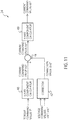
- a modified example 3 of the current command value calculator 24 not forming part of the invention will be described while referring to Fig. 11 and Fig. 12 .
- the current command value calculator 24 described above selects one of the two sets of current command values to calculate the current command values with which the output voltage becomes equal to or more than the target value V SET .
- one current command value is corrected to calculate the current command values with which the output voltage becomes equal to or more than the target value V SET .
- Fig. 11 is a diagram illustrating a configuration of the modified example 3 of the current command value calculator 24.
- the current command value calculator 24 includes a q axis component calculator 46, a corrector 47, an adder 48, and a d axis component calculator 49.
- the q axis component calculator 46 calculates a current command value iq3* based on the torque command value T*.
- the current command value iq3* is a value before correction of the q axis component of the current command value.
- the current command value calculator 24 in the present modified example corrects the current command value iq3*, thereby calculating the q axis component of the current command value.
- the current command value iq3* is calculated by any method in accordance with control desired to be realized by the controller, so that the torque of the SynRM1 becomes the torque command value T*.
- the q axis component calculator 46 calculates the current command value iq3* so that a magnitude of the current which is flowed through the stator becomes minimum.
- the q axis component calculator 46 may also calculate the current command value iq3* with which the current phase angle ⁇ becomes 135 degrees, by ignoring magnetic saturation, or it may also calculate the current command value iq3* with which the current phase angle ⁇ becomes a degree larger than 135 degrees, by taking the magnetic saturation into consideration. Further, the q axis component calculator 46 may also calculate the current command value iq3* so that the efficiency and the power factor of the SynRM1 become maximum.
- the current command value iq3* calculated by the q axis component calculator 46 is input into the adder 48.
- the voltage command values vdc*, vqc* are input into the corrector 47 from the voltage command value calculator 25.
- the corrector 47 calculates a correction value ⁇ iq*, based on the voltage command values vdc*, vqc*.
- the correction value ⁇ iq* is a current command value for calculating the q axis component iqc* of the current command value by correcting the current command value iq3*. Details of the corrector 47 will be described later.
- the correction value ⁇ iq* calculated by the corrector 47 is input into the adder 48.
- the adder 48 adds the correction value ⁇ iq* to the current command value iq3*, to thereby calculate the current command value iqc*.
- the current command value iqc* calculated by the adder 48 is input into the d axis component calculator 49.
- the d axis component calculator 49 calculates the d axis component idc* of the current command value based on the torque command value T* and the current command value iqc*, so that the torque of the SynRM1 becomes the torque command value T*.
- Fig. 12 is a diagram illustrating a configuration of the corrector 47. As illustrated in Fig. 12 , the corrector 47 includes an output voltage calculator 61, a subtracter 62, a limiter 63, and a PI controller 64.
- the voltage command values vdc*, vqc* calculated by the voltage command value calculator 25 are input into the output voltage calculator 61.
- the output voltage calculator 61 calculates the output voltage V 1 of the SynRM1, based on the voltage command values vdc*, vqc*.
- the output voltage V 1 calculated by the output voltage calculator 61 is input into the subtracter 62.
- the subtracter 62 subtracts the output voltage V 1 from the target value V SET of the output voltage, thereby calculating an error ⁇ V of the output voltage.
- the error ⁇ V calculated by the subtracter 62 is input into the limiter 63.
- the limiter 63 limits the error ⁇ V to 0 or more. Namely, the limiter 63 outputs only the error ⁇ V of 0 or more.
- the error ⁇ V output by the limiter 63 is input into the PI controller 64.
- the PI controller 64 performs PI control based on the error ⁇ V which is limited to 0 or more, to thereby calculate the correction value ⁇ iq* with which the output voltage V 1 of the SynRM1 becomes equal to or more than the target value V SET .
- the correction value ⁇ iq* calculated by the PI controller 64 is input into the adder 48.
- the correction value ⁇ iq* is added to the current command value as an offset current to make the output voltage V 1 to be equal to or more than the target value V SET . Consequently, it is possible to set the output voltage V 1 under the low load to be equal to or more than the target value V SET .
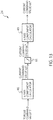
- a modified example 4 of the current command value calculator 24 not forming part of the invention will be described while referring to Fig. 13 .
- one current command value is corrected to calculate the current command values with which the output voltage becomes equal to or more than the target value V SET , in a similar manner to the modified example 3.
- the correction value ⁇ iq* is generated by the corrector 47, and the correction value ⁇ iq* is added to the current command value iq3* in the adder 48, to thereby generate the current command value iqc*.
- a lower limit of the current command value iq3* is limited by a lower-limit limiter 91, to thereby generate the current command value iqc*.
- the lower-limit limiter 91 corrects (limits) the iq3* so that the iqc* becomes equal to or more than the iq SET , as illustrated in Fig. 9 .
- Fig. 14 is a diagram illustrating a configuration of a system according to the present embodiment. As illustrated in Fig. 14 , the controller 2 according to the present embodiment further includes a torque command value calculator 29. The other configurations are similar to those of the first embodiment.
- the torque command value calculator (speed controller) 29 calculates the torque command value T* based on a speed command value ⁇ * and the estimated speed ⁇ est.
- the speed command value ⁇ * indicates an angular speed of rotating the rotor of the SynRM1.
- the torque command value T* calculated by the torque command value calculator 29 is input into the current command value calculator 24. Note that in the present embodiment, it is set that the speed command value ⁇ * is input from an external device.
- Fig. 15 is a diagram illustrating a configuration of the torque command value calculator 29. As illustrated in Fig. 15 , the torque command value calculator 29 includes a subtracter 71, and a PI controller 72.
- the speed command value ⁇ * and the estimated speed ⁇ est are input into the subtracter 71.
- the subtracter 71 subtracts the estimated speed ⁇ est from the speed command value ⁇ *, to thereby calculate an error ⁇ of the angular speed of the rotor.
- the error ⁇ calculated by the subtracter 71 is input into the PI controller 72.
- the PI controller 72 performs PI control based on the error ⁇ , and calculates the torque command value T* with which the error ⁇ becomes 0.
- the torque command value T* calculated by the PI controller 72 is input into the current command value calculator 24.
- Fig. 16 is a diagram illustrating another configuration of the current command value calculator 24 in an example not forming part of the invention.
- the current command value calculator 24 calculates the current command values idc*, iqc*, based on the torque command value T* and a phase angle command value ⁇ *.
- the current command value calculator 24 includes an output voltage calculator 81, a subtracter 82, a limiter 83, a PI controller 84, a phase angle command value calculator 85, a subtracter 86, and a current command value obtainer 87.
- the voltage command values vdc*, vqc* calculated by the voltage command value calculator 25 are input into the output voltage calculator 81.
- the output voltage calculator 81 calculates the output voltage V 1 of the SynRM1, based on the voltage command values vdc*, vqc*.
- the output voltage V 1 calculated by the output voltage calculator 81 is input into the subtracter 82.
- the subtracter 82 subtracts the output voltage V 1 from the target value V SET of the output voltage, to thereby calculate an error ⁇ V of the output voltage.
- the error ⁇ V calculated by the subtracter 82 is input into the limiter 83.
- the limiter 83 limits the error ⁇ V to 0 or more. Namely, the limiter 83 outputs only the error ⁇ V of 0 or more.
- the error ⁇ V output by the limiter 83 is input into the PI controller 84.
- the PI controller 84 performs PI control based on the error ⁇ V which is limited to 0 or more, to thereby calculate a correction value ⁇ * with which the output voltage V 1 of the SynRM1 becomes equal to or more than the target value V SET .
- the correction value ⁇ * is a phase angle command value for calculating the phase angle command value ⁇ * by correcting the phase angle command value ⁇ 1*.
- the correction value ⁇ * calculated by the PI controller 84 is input into the subtracter 86.
- the phase angle command value calculator 85 calculates the phase angle command value ⁇ 1* based on the torque command value T*.
- the phase angle command value ⁇ 1* is a value before correction of the phase angle command value ⁇ *.
- the phase angle command value ⁇ 1* is calculated by any method in accordance with control desired to be realized by the controller, so that the torque of the SynRM1 becomes the torque command value T*.
- the phase angle command value calculator 85 calculates the phase angle command value ⁇ 1* so that a magnitude of the current which is flowed through the stator becomes minimum.
- the phase angle command value calculator 85 may also set the phase angle command value ⁇ 1* to 135 degrees, by ignoring magnetic saturation, or it may also set the phase angle command value ⁇ 1* to a degree larger than 135 degrees, by taking the magnetic saturation into consideration.
- the phase angle command value calculator 85 may also calculate the phase angle command value ⁇ 1* so that the efficiency and the power factor of the SynRM1 become maximum.
- phase angle command value ⁇ 1* calculated by the phase angle command value calculator 85 is input into the subtracter 86.
- the subtracter 86 subtracts the correction value ⁇ * from the phase angle command value ⁇ 1*, to thereby calculate the phase angle command value ⁇ *.
- the phase angle command value ⁇ * calculated by the subtracter 86 is input into the current command value obtainer 87.
- the current command value obtainer 87 calculates the current command values idc*, iqc*, based on the torque command value T* and the phase angle command value ⁇ *. Concretely, the current command value obtainer 87 is only required to obtain coordinates of a point, on the equal torque curve of the toque command value T*, at which the current phase angle becomes the phase angle command value ⁇ *.
- the current command values idc*, iqc* obtained by the current command value obtainer 87 are input into the voltage command value calculator 25.
- the current command value calculator 24 in Fig. 16 corrects the current phase angle so that the output voltage V 1 becomes equal to or more than the target value V SET .
- the current command value calculator 24 corrects the current phase angle in a delay direction so that the current command values are shifted to the q axis side. Consequently, it is possible to make the output voltage V 1 under the low load to be equal to or more than the target value V SET .
- the required accuracy of torque control with respect to the controller 2 according to the present embodiment is lower than that with respect to the first embodiment. This is because the controller 2 according to the present embodiment performs control to make the speed ⁇ of the SynRM1 to be the speed command value ⁇ *.
- the current command value calculator 24 can calculate the current command values without using a table for correctly controlling the torque of the SynRM1 (a table in which the output voltage for each of the current command values is stored, or the like).
- 1 synchronous reluctance motor (SynRM), 2: inverter controller, 21: inverter, 22: current detector, 23: coordinate transformer, 24: current command value calculator, 25: voltage command value calculator, 26: coordinate transformer, 27: PWM modulator, 28: speed and rotational phase angle estimator, 29: torque command value calculator, 31: phase difference ⁇ setter, 32: ⁇ voltage calculator, 33: ⁇ voltage estimator, 34: subtracter, 35: PI controller, 36: integrator, 41: first calculator, 42: second calculator, 43: selector, 44: q axis component calculator, 45: d axis component calculator, 46: q axis component calculator, 47: corrector, 48: adder, 49: d axis component calculator, 51: first current vector, 52: second current vector, 53: equal torque curve, 54: equal voltage ellipse, 61: output voltage calculator, 62: subtracter, 63: limiter, 64: PI controller, 71: subtracter, 72: PI controller, 81
Claims (9)
- Eine Wechselrichtersteuerung (2), umfassend:eine Wechselrichterschaltung (21), die konfiguriert ist, eine Drehvorrichtung anzutreibenStromdetektoren (22), die konfiguriert sind, Stromwerte zu erfassen, die von der Wechselrichterschaltung (21) ausgegeben werden;einen Strombefehlswertrechner (24), der konfiguriert ist, Strombefehlswerte zu berechnen, so dass eine von der Drehvorrichtung erzeugte Ausgangsspannung auf der Grundlage eines von der Wechselrichterschaltung (21) ausgegebenen Stroms gleich oder größer als ein gegebener Wert wird;einen Spannungsbefehlswertrechner (25), der konfiguriert ist, Spannungsbefehlswerte so zu berechnen, dass die Stromwerte gleich den Strombefehlswerten werden; undeinen Schätzer (28), der konfiguriert ist, einen Drehphasenwinkel der Drehvorrichtung zu schätzen, basierend auf den Spannungsbefehlswerten und den Stromwerten,dadurch gekennzeichnet, dassder Strombefehlswertrechner (24) konfiguriert ist, erste Strombefehlswerte basierend auf einem Drehmomentbefehlswert und zweite Strombefehlswerte basierend auf dem Drehmomentbefehlswert bzw. einer geschätzten Geschwindigkeit zu berechnen, zu bestimmen, ob die Ausgangsspannung in Übereinstimmung mit den ersten Strombefehlswerten niedriger als der gegebene Wert ist, die ersten Strombefehlswerte als die Strombefehlswerte auszugeben, wenn die Ausgangsspannung in Übereinstimmung mit den ersten Strombefehlswerten gleich oder größer als der gegebene Wert ist, und die zweiten Strombefehlswerte als die Strombefehlswerte auszugeben, wenn die Ausgangsspannung in Übereinstimmung mit den ersten Strombefehlswerten niedriger als der gegebene Wert ist.
- Die Wechselrichtersteuerung (2) nach Anspruch 1, wobei
die Ausgangsspannung gemäß den zweiten Stromsollwerten als der gegebene Wert verwendet wird. - Die Wechselrichtersteuerung (2) nach Anspruch 2, wobei
der Stromsollwertrechner (24) ferner konfiguriert ist, die ersten Stromsollwerte basierend auf einem Drehmomentsollwert und die zweiten Stromsollwerte basierend auf dem Drehmomentsollwert bzw. einer geschätzten Drehzahl zu berechnen und die ersten Stromsollwerte oder die zweiten Stromsollwerte, deren Stromphasenwinkel näher an einer q-Achse liegt, als die Stromsollwerte auszugeben. - Die Wechselrichtersteuerung (2) nach Anspruch 2, wobei
der Stromsollwertrechner (24) ferner konfiguriert ist, die ersten Stromsollwerte auf der Grundlage eines Drehmomentsollwerts bzw. die zweiten Stromsollwerte auf der Grundlage des Drehmomentsollwerts und einer geschätzten Drehzahl zu berechnen und die ersten Stromsollwerte oder die zweiten Stromsollwerte, die eine größere q-Achsenkomponente aufweisen, als die Stromsollwerte auszugeben. - Die Wechselrichtersteuerung (2) nach Anspruch 1 oder 2, wobei
der Stromsollwertrechner (24) konfiguriert ist, einen Spannungswert der Ausgangsspannung, der basierend auf den ersten Stromsollwerten berechnet wird, mit dem gegebenen Wert zu vergleichen, wenn bestimmt wird, ob die Ausgangsspannung in Übereinstimmung mit den ersten Stromsollwerten niedriger als der gegebene Wert ist. - Die Wechselrichtersteuerung (2) nach Anspruch 2, wobei
der Stromsollwertrechner (24) konfiguriert ist, eine d-Achsenkomponente des ersten Stromsollwerts mit einer d-Achsenkomponente des zweiten Stromsollwerts zu vergleichen, wenn bestimmt wird, ob die Ausgangsspannung gemäß den ersten Stromsollwerten niedriger als der gegebene Wert ist. - Die Wechselrichtersteuerung (2) nach Anspruch 3, wobei
der Stromsollwertrechner (24) konfiguriert ist, einen Stromphasenwinkel der ersten Stromsollwerte mit einem Stromphasenwinkel der zweiten Stromsollwerte zu vergleichen, wenn bestimmt wird, welcher von dem Stromphasenwinkel der ersten Stromsollwerte und dem Stromphasenwinkel der zweiten Stromsollwerte näher an einer q-Achse liegt. - Die Wechselrichtersteuerung (2) nach einem der Ansprüche 1 bis 7, ferner umfassend einen Drehmomentsollwertrechner, der konfiguriert ist, den Drehmomentsollwert basierend auf einem Drehzahlsollwert und der geschätzten Drehzahl zu berechnen.
- Ein Motorantriebssystem, umfassend:eine Wechselrichtersteuerung (2) nach einem der vorhergehenden Ansprüche; undeine Drehvorrichtung in Form eines Motors.
Applications Claiming Priority (2)
| Application Number | Priority Date | Filing Date | Title |
|---|---|---|---|
| JP2015014722 | 2015-01-28 | ||
| PCT/JP2016/052161 WO2016121751A1 (ja) | 2015-01-28 | 2016-01-26 | インバータ制御装置及びモータ駆動システム |
Publications (3)
| Publication Number | Publication Date |
|---|---|
| EP3252941A1 EP3252941A1 (de) | 2017-12-06 |
| EP3252941A4 EP3252941A4 (de) | 2018-10-03 |
| EP3252941B1 true EP3252941B1 (de) | 2021-06-30 |
Family
ID=56543362
Family Applications (1)
| Application Number | Title | Priority Date | Filing Date |
|---|---|---|---|
| EP16743354.9A Active EP3252941B1 (de) | 2015-01-28 | 2016-01-26 | Wechselrichtersteuerungsvorrichtung und motorantriebssystem |
Country Status (5)
| Country | Link |
|---|---|
| US (1) | US10158305B2 (de) |
| EP (1) | EP3252941B1 (de) |
| JP (1) | JP6367332B2 (de) |
| CN (1) | CN107078674B (de) |
| WO (1) | WO2016121751A1 (de) |
Families Citing this family (16)
| Publication number | Priority date | Publication date | Assignee | Title |
|---|---|---|---|---|
| US10320322B2 (en) | 2016-04-15 | 2019-06-11 | Emerson Climate Technologies, Inc. | Switch actuation measurement circuit for voltage converter |
| US10277115B2 (en) | 2016-04-15 | 2019-04-30 | Emerson Climate Technologies, Inc. | Filtering systems and methods for voltage control |
| US9933842B2 (en) | 2016-04-15 | 2018-04-03 | Emerson Climate Technologies, Inc. | Microcontroller architecture for power factor correction converter |
| US10656026B2 (en) | 2016-04-15 | 2020-05-19 | Emerson Climate Technologies, Inc. | Temperature sensing circuit for transmitting data across isolation barrier |
| US10770966B2 (en) | 2016-04-15 | 2020-09-08 | Emerson Climate Technologies, Inc. | Power factor correction circuit and method including dual bridge rectifiers |
| US10763740B2 (en) | 2016-04-15 | 2020-09-01 | Emerson Climate Technologies, Inc. | Switch off time control systems and methods |
| US10305373B2 (en) | 2016-04-15 | 2019-05-28 | Emerson Climate Technologies, Inc. | Input reference signal generation systems and methods |
| TWI668953B (zh) * | 2016-08-22 | 2019-08-11 | 日商東芝股份有限公司 | Inverter control device and drive system |
| TWI654827B (zh) * | 2016-09-05 | 2019-03-21 | 日商東芝股份有限公司 | 換流器控制裝置及馬達驅動系統 |
| JP6776066B2 (ja) | 2016-09-05 | 2020-10-28 | 東芝インフラシステムズ株式会社 | インバータ制御装置および電動機駆動システム |
| JP2020031454A (ja) * | 2016-12-28 | 2020-02-27 | アルプスアルパイン株式会社 | 直流整流子電動機の回転に関する情報を取得する装置及び方法 |
| US11296633B2 (en) | 2018-01-12 | 2022-04-05 | Mitsubishi Electric Corporation | Rotary machine control device |
| DK3522362T3 (da) * | 2018-02-01 | 2024-03-04 | Siemens Gamesa Renewable Energy As | Styring af en elektrisk permanentmagnetmaskine med multiviklingssæt |
| JP7032250B2 (ja) * | 2018-06-28 | 2022-03-08 | 株式会社日立産機システム | 電力変換装置 |
| CN112039401A (zh) * | 2019-05-17 | 2020-12-04 | 杭州三花研究院有限公司 | 一种控制方法和控制装置及其系统 |
| CN113839605B (zh) * | 2020-06-23 | 2024-03-15 | 苏州宝时得电动工具有限公司 | 电机转速控制方法及装置 |
Family Cites Families (16)
| Publication number | Priority date | Publication date | Assignee | Title |
|---|---|---|---|---|
| JP4061517B2 (ja) * | 1998-07-16 | 2008-03-19 | 株式会社安川電機 | 交流電動機の可変速制御装置 |
| KR100354775B1 (ko) * | 2000-03-25 | 2002-11-04 | 엘지전자 주식회사 | 동기 릴럭턴스 모터의 속도 제어장치 |
| KR100421373B1 (ko) * | 2001-06-20 | 2004-03-06 | 엘지전자 주식회사 | 동기 릴럭턴스 모터의 회전 속도 제어장치 |
| EP1411629A1 (de) * | 2001-07-04 | 2004-04-21 | Kabushiki Kaisha Yaskawa Denki | Verfahren und einrichtung zur steuerung von strömen eines synchronen motors |
| JP3692085B2 (ja) | 2002-02-21 | 2005-09-07 | 株式会社東芝 | モータ制御方法及び装置 |
| WO2003081765A1 (fr) * | 2002-03-22 | 2003-10-02 | Matsushita Electric Industrial Co., Ltd. | Dispositif de commande d'un moteur a reluctance synchrone |
| JP4579627B2 (ja) | 2004-09-02 | 2010-11-10 | 三菱電機株式会社 | 回転機の制御装置 |
| JP4715158B2 (ja) * | 2004-10-19 | 2011-07-06 | 富士電機システムズ株式会社 | 誘導電動機の可変速制御装置 |
| JP5267848B2 (ja) * | 2008-04-15 | 2013-08-21 | 株式会社ジェイテクト | モータ制御装置 |
| JP2010119284A (ja) * | 2008-10-16 | 2010-05-27 | Panasonic Corp | モータ駆動装置 |
| JP4746667B2 (ja) | 2008-11-26 | 2011-08-10 | 本田技研工業株式会社 | 電動機の相電流推定装置および電動機の磁極位置推定装置 |
| JP2010136586A (ja) * | 2008-12-08 | 2010-06-17 | Honda Motor Co Ltd | 電動機の磁極位置推定装置 |
| JP4819970B2 (ja) * | 2008-12-15 | 2011-11-24 | 三菱電機株式会社 | 電動機駆動用電力変換装置 |
| JP5971707B2 (ja) * | 2011-08-29 | 2016-08-17 | 株式会社東芝 | 同期電動機のセンサレス制御装置ならびにインバータ装置 |
| US9438153B2 (en) * | 2013-03-28 | 2016-09-06 | Aisin Aw Co., Ltd. | Rotary electric machine control device |
| JP6193006B2 (ja) * | 2013-06-20 | 2017-09-06 | 株式会社東芝 | 電気車制御装置 |
-
2016
- 2016-01-26 EP EP16743354.9A patent/EP3252941B1/de active Active
- 2016-01-26 WO PCT/JP2016/052161 patent/WO2016121751A1/ja active Application Filing
- 2016-01-26 CN CN201680003392.4A patent/CN107078674B/zh active Active
- 2016-01-26 JP JP2016535264A patent/JP6367332B2/ja active Active
-
2017
- 2017-06-28 US US15/636,198 patent/US10158305B2/en active Active
Also Published As
| Publication number | Publication date |
|---|---|
| US10158305B2 (en) | 2018-12-18 |
| US20170317623A1 (en) | 2017-11-02 |
| EP3252941A1 (de) | 2017-12-06 |
| EP3252941A4 (de) | 2018-10-03 |
| JP6367332B2 (ja) | 2018-08-01 |
| JPWO2016121751A1 (ja) | 2017-04-27 |
| CN107078674A (zh) | 2017-08-18 |
| WO2016121751A1 (ja) | 2016-08-04 |
| CN107078674B (zh) | 2019-09-17 |
Similar Documents
| Publication | Publication Date | Title |
|---|---|---|
| EP3252941B1 (de) | Wechselrichtersteuerungsvorrichtung und motorantriebssystem | |
| EP1748550B1 (de) | Synchron-maschinensteuerung | |
| JP5130031B2 (ja) | 永久磁石モータの位置センサレス制御装置 | |
| EP2892147B1 (de) | Elektromotorsteuerungsvorrichtung | |
| US8044618B2 (en) | Control apparatus for AC motor | |
| US8378601B2 (en) | Control apparatus for permanent magnet synchronous motor | |
| US20170264227A1 (en) | Inverter control device and motor drive system | |
| WO2012014526A1 (ja) | 交流回転機の制御装置 | |
| EP2424105A2 (de) | Vektorsteuerungsvorrichtung und Motorsteuersystem | |
| EP3509210B1 (de) | Wandlersteuerungsvorrichtung und elektromotorantriebssystem | |
| WO2008004417A1 (fr) | Appareil de commande sans capteur de machine synchrone | |
| EP2916452B1 (de) | Verfahren zur steuerung des primären magnetflusses | |
| US9553532B2 (en) | Control device for alternating current rotary machine | |
| EP1681762B1 (de) | Synchronmotorantriebssystem und Verfahren | |
| JP5499965B2 (ja) | 交流回転機の制御装置 | |
| JP4053511B2 (ja) | 巻線界磁式同期機のベクトル制御装置 | |
| JP2009284684A (ja) | ベクトル制御装置 | |
| JP3692085B2 (ja) | モータ制御方法及び装置 | |
| JP5660191B2 (ja) | 電動機制御装置 | |
| JPH06225574A (ja) | 電動機の制御方法及び装置 | |
| EP4075665A1 (de) | Stromwandler | |
| JP2009100600A (ja) | インバータ制御装置とその制御方法 | |
| JP2018011437A (ja) | モータ制御装置 | |
| JP2007166729A (ja) | 電動機制御装置 |
Legal Events
| Date | Code | Title | Description |
|---|---|---|---|
| STAA | Information on the status of an ep patent application or granted ep patent |
Free format text: STATUS: THE INTERNATIONAL PUBLICATION HAS BEEN MADE |
|
| PUAI | Public reference made under article 153(3) epc to a published international application that has entered the european phase |
Free format text: ORIGINAL CODE: 0009012 |
|
| STAA | Information on the status of an ep patent application or granted ep patent |
Free format text: STATUS: REQUEST FOR EXAMINATION WAS MADE |
|
| 17P | Request for examination filed |
Effective date: 20170629 |
|
| AK | Designated contracting states |
Kind code of ref document: A1 Designated state(s): AL AT BE BG CH CY CZ DE DK EE ES FI FR GB GR HR HU IE IS IT LI LT LU LV MC MK MT NL NO PL PT RO RS SE SI SK SM TR |
|
| AX | Request for extension of the european patent |
Extension state: BA ME |
|
| DAV | Request for validation of the european patent (deleted) | ||
| DAX | Request for extension of the european patent (deleted) | ||
| A4 | Supplementary search report drawn up and despatched |
Effective date: 20180831 |
|
| RIC1 | Information provided on ipc code assigned before grant |
Ipc: H02P 6/18 20160101AFI20180827BHEP Ipc: H02P 21/24 20160101ALI20180827BHEP Ipc: H02P 25/08 20160101ALN20180827BHEP Ipc: H02P 21/22 20160101ALI20180827BHEP |
|
| GRAP | Despatch of communication of intention to grant a patent |
Free format text: ORIGINAL CODE: EPIDOSNIGR1 |
|
| STAA | Information on the status of an ep patent application or granted ep patent |
Free format text: STATUS: GRANT OF PATENT IS INTENDED |
|
| INTG | Intention to grant announced |
Effective date: 20210211 |
|
| RIC1 | Information provided on ipc code assigned before grant |
Ipc: H02P 6/18 20160101AFI20210129BHEP Ipc: H02P 21/24 20160101ALI20210129BHEP Ipc: H02P 21/22 20160101ALI20210129BHEP Ipc: H02P 25/08 20160101ALN20210129BHEP |
|
| GRAS | Grant fee paid |
Free format text: ORIGINAL CODE: EPIDOSNIGR3 |
|
| GRAA | (expected) grant |
Free format text: ORIGINAL CODE: 0009210 |
|
| STAA | Information on the status of an ep patent application or granted ep patent |
Free format text: STATUS: THE PATENT HAS BEEN GRANTED |
|
| AK | Designated contracting states |
Kind code of ref document: B1 Designated state(s): AL AT BE BG CH CY CZ DE DK EE ES FI FR GB GR HR HU IE IS IT LI LT LU LV MC MK MT NL NO PL PT RO RS SE SI SK SM TR |
|
| REG | Reference to a national code |
Ref country code: CH Ref legal event code: EP |
|
| REG | Reference to a national code |
Ref country code: AT Ref legal event code: REF Ref document number: 1407297 Country of ref document: AT Kind code of ref document: T Effective date: 20210715 |
|
| REG | Reference to a national code |
Ref country code: DE Ref legal event code: R096 Ref document number: 602016059979 Country of ref document: DE |
|
| REG | Reference to a national code |
Ref country code: IE Ref legal event code: FG4D |
|
| REG | Reference to a national code |
Ref country code: LT Ref legal event code: MG9D |
|
| PG25 | Lapsed in a contracting state [announced via postgrant information from national office to epo] |
Ref country code: FI Free format text: LAPSE BECAUSE OF FAILURE TO SUBMIT A TRANSLATION OF THE DESCRIPTION OR TO PAY THE FEE WITHIN THE PRESCRIBED TIME-LIMIT Effective date: 20210630 Ref country code: HR Free format text: LAPSE BECAUSE OF FAILURE TO SUBMIT A TRANSLATION OF THE DESCRIPTION OR TO PAY THE FEE WITHIN THE PRESCRIBED TIME-LIMIT Effective date: 20210630 Ref country code: BG Free format text: LAPSE BECAUSE OF FAILURE TO SUBMIT A TRANSLATION OF THE DESCRIPTION OR TO PAY THE FEE WITHIN THE PRESCRIBED TIME-LIMIT Effective date: 20210930 |
|
| REG | Reference to a national code |
Ref country code: NL Ref legal event code: MP Effective date: 20210630 |
|
| REG | Reference to a national code |
Ref country code: AT Ref legal event code: MK05 Ref document number: 1407297 Country of ref document: AT Kind code of ref document: T Effective date: 20210630 |
|
| PG25 | Lapsed in a contracting state [announced via postgrant information from national office to epo] |
Ref country code: NO Free format text: LAPSE BECAUSE OF FAILURE TO SUBMIT A TRANSLATION OF THE DESCRIPTION OR TO PAY THE FEE WITHIN THE PRESCRIBED TIME-LIMIT Effective date: 20210930 Ref country code: SE Free format text: LAPSE BECAUSE OF FAILURE TO SUBMIT A TRANSLATION OF THE DESCRIPTION OR TO PAY THE FEE WITHIN THE PRESCRIBED TIME-LIMIT Effective date: 20210630 Ref country code: RS Free format text: LAPSE BECAUSE OF FAILURE TO SUBMIT A TRANSLATION OF THE DESCRIPTION OR TO PAY THE FEE WITHIN THE PRESCRIBED TIME-LIMIT Effective date: 20210630 Ref country code: GR Free format text: LAPSE BECAUSE OF FAILURE TO SUBMIT A TRANSLATION OF THE DESCRIPTION OR TO PAY THE FEE WITHIN THE PRESCRIBED TIME-LIMIT Effective date: 20211001 Ref country code: LV Free format text: LAPSE BECAUSE OF FAILURE TO SUBMIT A TRANSLATION OF THE DESCRIPTION OR TO PAY THE FEE WITHIN THE PRESCRIBED TIME-LIMIT Effective date: 20210630 |
|
| PG25 | Lapsed in a contracting state [announced via postgrant information from national office to epo] |
Ref country code: NL Free format text: LAPSE BECAUSE OF FAILURE TO SUBMIT A TRANSLATION OF THE DESCRIPTION OR TO PAY THE FEE WITHIN THE PRESCRIBED TIME-LIMIT Effective date: 20210630 Ref country code: PT Free format text: LAPSE BECAUSE OF FAILURE TO SUBMIT A TRANSLATION OF THE DESCRIPTION OR TO PAY THE FEE WITHIN THE PRESCRIBED TIME-LIMIT Effective date: 20211102 Ref country code: RO Free format text: LAPSE BECAUSE OF FAILURE TO SUBMIT A TRANSLATION OF THE DESCRIPTION OR TO PAY THE FEE WITHIN THE PRESCRIBED TIME-LIMIT Effective date: 20210630 Ref country code: ES Free format text: LAPSE BECAUSE OF FAILURE TO SUBMIT A TRANSLATION OF THE DESCRIPTION OR TO PAY THE FEE WITHIN THE PRESCRIBED TIME-LIMIT Effective date: 20210630 Ref country code: AT Free format text: LAPSE BECAUSE OF FAILURE TO SUBMIT A TRANSLATION OF THE DESCRIPTION OR TO PAY THE FEE WITHIN THE PRESCRIBED TIME-LIMIT Effective date: 20210630 Ref country code: SK Free format text: LAPSE BECAUSE OF FAILURE TO SUBMIT A TRANSLATION OF THE DESCRIPTION OR TO PAY THE FEE WITHIN THE PRESCRIBED TIME-LIMIT Effective date: 20210630 Ref country code: SM Free format text: LAPSE BECAUSE OF FAILURE TO SUBMIT A TRANSLATION OF THE DESCRIPTION OR TO PAY THE FEE WITHIN THE PRESCRIBED TIME-LIMIT Effective date: 20210630 Ref country code: CZ Free format text: LAPSE BECAUSE OF FAILURE TO SUBMIT A TRANSLATION OF THE DESCRIPTION OR TO PAY THE FEE WITHIN THE PRESCRIBED TIME-LIMIT Effective date: 20210630 Ref country code: EE Free format text: LAPSE BECAUSE OF FAILURE TO SUBMIT A TRANSLATION OF THE DESCRIPTION OR TO PAY THE FEE WITHIN THE PRESCRIBED TIME-LIMIT Effective date: 20210630 |
|
| PG25 | Lapsed in a contracting state [announced via postgrant information from national office to epo] |
Ref country code: PL Free format text: LAPSE BECAUSE OF FAILURE TO SUBMIT A TRANSLATION OF THE DESCRIPTION OR TO PAY THE FEE WITHIN THE PRESCRIBED TIME-LIMIT Effective date: 20210630 |
|
| REG | Reference to a national code |
Ref country code: DE Ref legal event code: R097 Ref document number: 602016059979 Country of ref document: DE |
|
| PG25 | Lapsed in a contracting state [announced via postgrant information from national office to epo] |
Ref country code: DK Free format text: LAPSE BECAUSE OF FAILURE TO SUBMIT A TRANSLATION OF THE DESCRIPTION OR TO PAY THE FEE WITHIN THE PRESCRIBED TIME-LIMIT Effective date: 20210630 |
|
| PLBE | No opposition filed within time limit |
Free format text: ORIGINAL CODE: 0009261 |
|
| STAA | Information on the status of an ep patent application or granted ep patent |
Free format text: STATUS: NO OPPOSITION FILED WITHIN TIME LIMIT |
|
| PG25 | Lapsed in a contracting state [announced via postgrant information from national office to epo] |
Ref country code: AL Free format text: LAPSE BECAUSE OF FAILURE TO SUBMIT A TRANSLATION OF THE DESCRIPTION OR TO PAY THE FEE WITHIN THE PRESCRIBED TIME-LIMIT Effective date: 20210630 |
|
| 26N | No opposition filed |
Effective date: 20220331 |
|
| PG25 | Lapsed in a contracting state [announced via postgrant information from national office to epo] |
Ref country code: IT Free format text: LAPSE BECAUSE OF FAILURE TO SUBMIT A TRANSLATION OF THE DESCRIPTION OR TO PAY THE FEE WITHIN THE PRESCRIBED TIME-LIMIT Effective date: 20210630 |
|
| PG25 | Lapsed in a contracting state [announced via postgrant information from national office to epo] |
Ref country code: MC Free format text: LAPSE BECAUSE OF FAILURE TO SUBMIT A TRANSLATION OF THE DESCRIPTION OR TO PAY THE FEE WITHIN THE PRESCRIBED TIME-LIMIT Effective date: 20210630 |
|
| REG | Reference to a national code |
Ref country code: CH Ref legal event code: PL |
|
| GBPC | Gb: european patent ceased through non-payment of renewal fee |
Effective date: 20220126 |
|
| REG | Reference to a national code |
Ref country code: BE Ref legal event code: MM Effective date: 20220131 |
|
| PG25 | Lapsed in a contracting state [announced via postgrant information from national office to epo] |
Ref country code: LU Free format text: LAPSE BECAUSE OF NON-PAYMENT OF DUE FEES Effective date: 20220126 Ref country code: GB Free format text: LAPSE BECAUSE OF NON-PAYMENT OF DUE FEES Effective date: 20220126 |
|
| PG25 | Lapsed in a contracting state [announced via postgrant information from national office to epo] |
Ref country code: BE Free format text: LAPSE BECAUSE OF NON-PAYMENT OF DUE FEES Effective date: 20220131 |
|
| PG25 | Lapsed in a contracting state [announced via postgrant information from national office to epo] |
Ref country code: LI Free format text: LAPSE BECAUSE OF NON-PAYMENT OF DUE FEES Effective date: 20220131 Ref country code: CH Free format text: LAPSE BECAUSE OF NON-PAYMENT OF DUE FEES Effective date: 20220131 |
|
| PG25 | Lapsed in a contracting state [announced via postgrant information from national office to epo] |
Ref country code: IE Free format text: LAPSE BECAUSE OF NON-PAYMENT OF DUE FEES Effective date: 20220126 |
|
| PG25 | Lapsed in a contracting state [announced via postgrant information from national office to epo] |
Ref country code: LT Free format text: LAPSE BECAUSE OF FAILURE TO SUBMIT A TRANSLATION OF THE DESCRIPTION OR TO PAY THE FEE WITHIN THE PRESCRIBED TIME-LIMIT Effective date: 20210630 |
|
| PGFP | Annual fee paid to national office [announced via postgrant information from national office to epo] |
Ref country code: DE Payment date: 20221130 Year of fee payment: 8 |
|
| PGFP | Annual fee paid to national office [announced via postgrant information from national office to epo] |
Ref country code: FR Payment date: 20231212 Year of fee payment: 9 |
|
| PG25 | Lapsed in a contracting state [announced via postgrant information from national office to epo] |
Ref country code: HU Free format text: LAPSE BECAUSE OF FAILURE TO SUBMIT A TRANSLATION OF THE DESCRIPTION OR TO PAY THE FEE WITHIN THE PRESCRIBED TIME-LIMIT; INVALID AB INITIO Effective date: 20160126 |