EP3252941B1 - Inverter control apparatus and motor driving system - Google Patents
Inverter control apparatus and motor driving system Download PDFInfo
- Publication number
- EP3252941B1 EP3252941B1 EP16743354.9A EP16743354A EP3252941B1 EP 3252941 B1 EP3252941 B1 EP 3252941B1 EP 16743354 A EP16743354 A EP 16743354A EP 3252941 B1 EP3252941 B1 EP 3252941B1
- Authority
- EP
- European Patent Office
- Prior art keywords
- current command
- current
- command value
- command values
- values
- Prior art date
- Legal status (The legal status is an assumption and is not a legal conclusion. Google has not performed a legal analysis and makes no representation as to the accuracy of the status listed.)
- Active
Links
- 238000010586 diagram Methods 0.000 description 27
- 238000000034 method Methods 0.000 description 10
- 238000004364 calculation method Methods 0.000 description 7
- 230000004907 flux Effects 0.000 description 5
- 230000009466 transformation Effects 0.000 description 5
- 230000001360 synchronised effect Effects 0.000 description 4
- 230000005284 excitation Effects 0.000 description 2
- 230000001419 dependent effect Effects 0.000 description 1
- 230000003993 interaction Effects 0.000 description 1
- 238000004804 winding Methods 0.000 description 1
Images


Classifications
-
- H—ELECTRICITY
- H02—GENERATION; CONVERSION OR DISTRIBUTION OF ELECTRIC POWER
- H02P—CONTROL OR REGULATION OF ELECTRIC MOTORS, ELECTRIC GENERATORS OR DYNAMO-ELECTRIC CONVERTERS; CONTROLLING TRANSFORMERS, REACTORS OR CHOKE COILS
- H02P6/00—Arrangements for controlling synchronous motors or other dynamo-electric motors using electronic commutation dependent on the rotor position; Electronic commutators therefor
- H02P6/14—Electronic commutators
- H02P6/16—Circuit arrangements for detecting position
- H02P6/18—Circuit arrangements for detecting position without separate position detecting elements
- H02P6/182—Circuit arrangements for detecting position without separate position detecting elements using back-emf in windings
-
- H—ELECTRICITY
- H02—GENERATION; CONVERSION OR DISTRIBUTION OF ELECTRIC POWER
- H02P—CONTROL OR REGULATION OF ELECTRIC MOTORS, ELECTRIC GENERATORS OR DYNAMO-ELECTRIC CONVERTERS; CONTROLLING TRANSFORMERS, REACTORS OR CHOKE COILS
- H02P6/00—Arrangements for controlling synchronous motors or other dynamo-electric motors using electronic commutation dependent on the rotor position; Electronic commutators therefor
- H02P6/14—Electronic commutators
- H02P6/16—Circuit arrangements for detecting position
- H02P6/18—Circuit arrangements for detecting position without separate position detecting elements
-
- H—ELECTRICITY
- H02—GENERATION; CONVERSION OR DISTRIBUTION OF ELECTRIC POWER
- H02P—CONTROL OR REGULATION OF ELECTRIC MOTORS, ELECTRIC GENERATORS OR DYNAMO-ELECTRIC CONVERTERS; CONTROLLING TRANSFORMERS, REACTORS OR CHOKE COILS
- H02P21/00—Arrangements or methods for the control of electric machines by vector control, e.g. by control of field orientation
- H02P21/22—Current control, e.g. using a current control loop
-
- H—ELECTRICITY
- H02—GENERATION; CONVERSION OR DISTRIBUTION OF ELECTRIC POWER
- H02P—CONTROL OR REGULATION OF ELECTRIC MOTORS, ELECTRIC GENERATORS OR DYNAMO-ELECTRIC CONVERTERS; CONTROLLING TRANSFORMERS, REACTORS OR CHOKE COILS
- H02P21/00—Arrangements or methods for the control of electric machines by vector control, e.g. by control of field orientation
- H02P21/24—Vector control not involving the use of rotor position or rotor speed sensors
-
- H—ELECTRICITY
- H02—GENERATION; CONVERSION OR DISTRIBUTION OF ELECTRIC POWER
- H02P—CONTROL OR REGULATION OF ELECTRIC MOTORS, ELECTRIC GENERATORS OR DYNAMO-ELECTRIC CONVERTERS; CONTROLLING TRANSFORMERS, REACTORS OR CHOKE COILS
- H02P25/00—Arrangements or methods for the control of AC motors characterised by the kind of AC motor or by structural details
- H02P25/02—Arrangements or methods for the control of AC motors characterised by the kind of AC motor or by structural details characterised by the kind of motor
- H02P25/08—Reluctance motors
Definitions
- Embodiments of the present invention relate to an inverter controller and a motor driving system.
- An inverter controller and a motor driving system capable of estimating, with good accuracy, a rotational phase angle of a motor under a state of high speed and low load, are provided.
- FIG. 1 is a diagram illustrating a configuration of the system according to the present embodiment. As illustrated in Fig. 1 , the system according to the present embodiment includes a motor 1 and an inverter controller 2.
- the motor 1 is a rotary drive target of the controller 2, and is connected to the controller 2.
- the SynRM1 includes a stator and a rotor.
- the stator has three excitation phases (U phase, V phase, and W phase).
- the stator generates a magnetic field with the use of a three-phase alternating current which flows through each excitation phase.
- the rotor does not have a permanent magnet. The rotor is rotated through a magnetic interaction with the magnetic field generated by the stator.
- the inverter controller 2 (which is referred to as “controller 2", hereinafter) controls a rotational phase angle of the SynRM1 in a sensorless manner.
- the controller 2 includes an inverter 21, current detectors 22, a coordinate transformer 23, a current command value calculator 24, a voltage command value calculator 25, a coordinate transformer 26, a PWM modulator 27, and a speed and rotational phase angle estimator 28.
- the inverter 21 is a circuit including switching elements (transistors).
- the inverter 21 switches ON/OFF of the switching elements to convert power from a power source (whose illustration is omitted) into alternating-current power, and supplies it to the SynRM1.
- a control signal for controlling ON/OFF of the respective switching elements is input into the inverter 21 from the PWM modulator 27.
- the current detectors 22 detect current values of two phases or three phases, in the three-phase alternating current flowing through the stator of the SynRM1.
- Fig. 1 illustrates a configuration in which current values iu, iw of two phases (U phase and W phase) are detected.
- the coordinate transformer 23 performs coordinate transformation on the current values iu, iw detected by the current detectors 22, from a three-phase fixed coordinate system to a rotating coordinate system of dc and qc axes.
- the three-phase fixed coordinate system and the rotating coordinate system of dc and qc axes will be described with reference to Fig. 2 .
- the three-phase fixed coordinate system is a fixed coordinate system formed of an ⁇ axis and a ⁇ axis.
- the ⁇ axis is set in the U phase direction
- the ⁇ axis is set in a direction perpendicular to the ⁇ axis.
- the current values iu, iw detected by the current detectors 22 are represented on the three-phase fixed coordinates as described above.
- the rotating coordinate system of dc and qc axes is a rotating coordinate system formed of a dc axis and a qc axis.
- the dc axis is set in a direction which is estimated by the controller 2 as a d axis direction (a direction in which an inductance of the rotor is minimum)
- the qc axis is set in a direction which is estimated by the controller 2 as a q axis direction (a direction in which the inductance of the rotor is maximum).
- An inductance ellipse in Fig. 2 indicates an inductance of the rotor.
- an actual rotational phase angle ⁇ of the rotor is represented by an angle from the ⁇ axis to the d axis.
- an estimated rotational phase angle ⁇ est of the rotor estimated by the controller 2 is represented by an angle from the ⁇ axis to the dc axis. It is indicated that the closer the angle between the rotational phase angle ⁇ and the estimated rotational phase angle ⁇ est, the higher the estimation accuracy of the rotational phase angle.
- the coordinate transformer 23 can transform the three-phase fixed coordinate system into the rotating coordinate system of dc and qc axes, by using the estimated rotational phase angle ⁇ est output by the speed and rotational phase angle estimator 28.
- values obtained when the coordinate transformer 23 performs the coordinate transformation on the current values iu, iw are referred to as current values idc, iqc.
- the current value idc is a dc axis component of the current which flows through the stator
- the current value iqc is a qc axis component of the current which flows through the stator.
- the current command value calculator 24 calculates current command values idc*, iqc*, based on a torque command value T* and an estimated speed ⁇ est.
- the torque command value T* is a value of torque generated in the rotor. In the present embodiment, it is set that the torque command value T* is input from an external device.
- the estimated speed ⁇ est indicates an angular speed of the rotor estimated by the controller 2.
- the current command value idc* is a dc axis component of the current which is flowed through the SynRM1.
- the current command value iqc* is a qc axis component of the current which is flowed through the SynRM1. Details of the current command value calculator 24 will be described later.
- the voltage command value calculator 25 calculates voltage command values vdc*, vqc* with which the current values idc, iqc of the SynRM1 become equal to the current command values idc*, iqc*.
- the voltage command value vdc* is a dc axis component of a voltage applied to the stator of the SynRM1.
- the voltage command value vqc* is a qc axis component of the voltage applied to the stator of the SynRM1.
- the coordinate transformer 26 performs coordinate transformation on the voltage command values vdc*, vqc* output by the voltage command value calculator 25, from the rotating coordinate system of dc and qc axes to the three-phase fixed coordinate system.
- the coordinate transformer 26 can transform the rotating coordinate system of dc and qc axes into the three-phase fixed coordinate system by using the estimated rotational phase angle ⁇ est, in a similar manner to the coordinate transformer 23.
- values obtained when the coordinate transformer 26 performs the coordinate transformation on the voltage command values vdc*, vqc* are referred to as voltage command values vu*, vv*, vw*.
- the voltage command value vu* is a voltage applied to the U phase of the stator
- the voltage command value vv* is a voltage applied to the V phase of the stator
- the voltage command value vw* is a voltage applied to the W phase of the stator.
- the PWM modulator 27 modulates the voltage command values vu*, vv*, vw* through PWM (Pulse-Width Modulation) using a triangular wave, and generates a binary control signal corresponding to ON or OFF of each of the switching elements of the inverter 21.
- the PWM modulator 27 inputs the generated control signal into the inverter 21.
- the speed and rotational phase angle estimator 28 (which is referred to as “estimator 28", hereinafter) estimates a speed co and a rotational phase angle ⁇ of the rotor of the SynRM1, based on the torque command value T*, the voltage command values vdc*, vqc*, and the current values idc, iqc, and calculates the estimated speed coest and the estimated rotational phase angle ⁇ est.
- Fig. 3 is a diagram illustrating a configuration of the estimator 28.
- the estimator 28 includes a phase difference ⁇ setter 31, a ⁇ voltage calculator 32, a ⁇ voltage estimator 33, a subtracter 34, a PI controller 35, and an integrator 36.
- the phase difference ⁇ setter 31 outputs a phase difference ⁇ in accordance with the torque command value T*, from previously stored plural phase differences ⁇ .
- the phase difference ⁇ indicates a value or a range of phase difference which causes the largest voltage variation due to influence of an error ⁇ between the rotational phase angle ⁇ and the estimated rotational phase angle ⁇ est.
- the plural phase differences ⁇ are previously calculated in an analytic manner or experimental manner for each torque value, and stored in the phase difference ⁇ setter 31.
- the ⁇ voltage calculator 32 calculates a voltage value vy of a ⁇ voltage, based on the voltage command values vdc*, vqc*, and the phase difference ⁇ set (output) by the phase difference ⁇ setter 31.
- the ⁇ voltage is a feature amount which varies in accordance with the error ⁇ .
- the voltage value vy calculated by the ⁇ voltage calculator 32 is input into the subtracter 34.
- the ⁇ voltage estimator 33 calculates an estimated voltage value vyest of the ⁇ voltage, based on voltage values vdcest, vqcest, and the phase difference ⁇ set (output) by the phase difference ⁇ setter 31.
- the ⁇ voltage estimator 33 calculates the voltage values vdcest, vqcest, based on the current values idc, iqc, and the estimated speed ⁇ est.
- the voltage value vdcest is an estimated value of the dc axis component of the voltage applied to the stator of the SynRM1.
- the voltage value vqcest is an estimated value of the qc axis component of the voltage applied to the stator of the SynRM1.
- the voltage values vdcest, vqcest are calculated through the following expression.
- Rm indicates a winding resistance of the stator
- Ld indicates an inductance in the d axis direction
- Lq indicates an inductance in the q axis direction
- p indicates a differential operator (d/dt).
- the ⁇ voltage estimator 33 previously stores these values.
- the ⁇ voltage estimator 33 calculates the estimated voltage value vyest of the ⁇ voltage, based on the voltage values vdcest, vqcest, and the phase difference ⁇ .
- the estimated voltage value vyest calculated by the ⁇ voltage estimator 33 is input into the subtracter 34.
- the subtracter 34 subtracts the voltage value vy from the estimated voltage value vyest to calculate an error ⁇ v ⁇ of the ⁇ voltage.
- the ⁇ voltage varies in accordance with the error ⁇ , so that the error ⁇ v ⁇ is in proportion to the error ⁇ .
- the error ⁇ v ⁇ calculated by the subtracter 34 is input into the PI controller 35.
- the PI controller 35 performs PI control to make the error ⁇ v ⁇ become 0, to thereby estimate the speed ⁇ of the rotor and calculate the estimated speed ⁇ est.
- the estimated speed ⁇ est calculated by the PI controller 35 is sequentially fed back to the ⁇ voltage estimator 33, and is also input into the integrator 36.
- the integrator 36 integrates the estimated speed ⁇ est calculated by the PI controller 35, and calculates the estimated rotational phase angle ⁇ est.
- the estimator 28 can calculate the estimated speed ⁇ est and the estimated rotational phase angle ⁇ est.
- the estimated speed ⁇ est calculated by the estimator 28 is input into the current command value calculator 24. Further, the estimated rotational phase angle ⁇ est is input into the coordinate transformers 23, 26, and used for the coordinate transformation.
- the estimation method of the speed ⁇ and the rotational phase angle ⁇ performed by the estimator 28 is not limited to this, and any method can be selected from already-known estimation methods.
- the estimator 28 may also estimate the rotational phase angle ⁇ based on another method which uses a voltage generated by an interlinkage magnetic flux, it may also estimate the rotational phase angle ⁇ by using the interlinkage magnetic flux itself, or it may also estimate the rotational phase angle ⁇ by performing PI control so that a deviation of the q axis component of the current value becomes 0.
- the current command value calculator 24 calculates current command values so that an output voltage of the SynRM1 becomes equal to or more than a predetermined target value V SET .
- the target value V SET is a voltage value previously determined in an experimental manner or analytic manner, as an output voltage capable of accurately estimating the speed ⁇ and the rotational phase angle ⁇ .
- Fig. 4 is a diagram illustrating the configuration of the current command value calculator 24.
- the current command value calculator 24 includes a first calculator 41, a second calculator 42, and a selector 43.
- the first calculator 41 generates first current command values id1*, iq1*, based on the torque command value T*.
- the first current command value id1* is a dc axis component of the current which is flowed through the SynRM1.
- the first current command value iq1* is a qc axis component of the current which is flowed through the SynRM1.
- the first calculator 41 calculates the first current command values id1*, iq1*, so that a torque of the SynRM1 becomes the torque command value T*.
- Fig. 5 is a diagram explaining a calculation method of the current command values.
- a horizontal axis indicates idc
- a vertical axis indicates iqc
- an arrow mark 51 indicates a first current vector
- an arrow mark 52 indicates a second current vector
- a curve 53 indicates an equal torque curve of the torque command value T*
- a curve 54 indicates an equal voltage ellipse of the target value V SET .
- the first current vector 51 is a vector corresponding to the first current command values id1*, iq1*.
- the first current command values are represented by two values of (id1*, iq1*), but, they can also be represented by a magnitude of current (id1* 2 +iq1* 2 ) 1/2 and a current phase angle ⁇ 1. These representations can be mutually converted.
- the selection of any point on a plane in Fig. 5 corresponds to calculation (selection) of the first current command values.
- the first calculator 41 selects any point on the equal torque curve 53 of the torque command value T*, as the first current command values.
- the first calculator 41 can select the first current command values from a position on the equal torque curve 53, based on any method in accordance with control desired to be realized by the controller 2.
- the first calculator 41 selects the first current command values so that a magnitude of the current which is flowed through the stator (a magnitude of the first current vector) becomes minimum.
- the first calculator 41 may also select the first current command values with which the current phase angle ⁇ 1 becomes 135 degrees, by ignoring magnetic saturation, or it may also select the first current command values with which the current phase angle ⁇ 1 becomes a degree larger than 135 degrees, by taking the magnetic saturation into consideration. Further, the first calculator 41 may also select the first current command values so that efficiency and a power factor of the SynRM1 become maximum.
- the first calculator 41 may also select the first current command values as described above by referring to a table in which the first current command values for each torque value are stored, or it may also determine the first current command values as described above by calculation.
- the first current command values calculated by the first calculator 41 are input into the selector 43.
- the second calculator 42 calculates second current command values id2*, iq2*, based on the torque command value T* and the estimated speed ⁇ est.
- the second current command value id2* is a dc axis component of the current which is flowed through the SynRM1.
- the second current command value iq2* is a qc axis component of the current which is flowed through the SynRM1.
- the second calculator 42 calculates the second current command values id2*, iq2*, so that the torque of the SynRM1 becomes the torque command value T* and the output voltage of the SynRM1 becomes the target value V SET .
- the second current vector 52 in Fig. 5 is a vector corresponding to the second current command values id2*, iq2*.
- the second current command values are represented by two values of (id2*, iq2*), but, they can also be represented by a magnitude of current (id2* 2 +iq2* 2 ) 1/2 and a current phase angle ⁇ 2. These representations can be mutually converted.
- the selection of any point on the plane in Fig. 5 corresponds to calculation (selection) of the second current command values.
- the second calculator 42 selects, as the second current command values, any one of intersection points between the equal torque curve 53 of the torque command value T* and the equal voltage ellipse 54 of the target value V SET .
- the second calculator 42 selects the intersection point A, as illustrated in Fig. 5 .
- the intersection point A indicates an intersection point on the iqc axis side (on the q axis side), between the two intersection points.
- the equal voltage ellipse 54 becomes wide in the d axis direction and becomes narrow in the q axis direction, so that if the intersection point A on the q axis side is selected, a magnitude of the current which is flowed through the stator (a magnitude of the second current vector) becomes small, when compared to a case where the intersection point B on the d axis side is selected. For this reason, when the second calculator 42 selects the intersection point A, it is possible to save power of the controller 2.
- the second current command values correspond to the intersection point A.
- the second calculator 42 may also select the second current command values as described above by referring to a table in which the second current command values for each torque value are stored, or it may also determine the second current command values as described above by solving the following expression.
- V SET ⁇ est L q 2 i q 2 2 + L d 2 i d 2 2
- the second current command values calculated by the second calculator 42 are input into the selector 43.
- the selector 43 outputs the first current command values id1*, iq1* or the second current command values id2*, iq2*, as the current command values idc*, iqc*.
- the selector 43 determines whether or not an output voltage V 1 in accordance with the first current command values id1*, iq1* is lower than the target value V SET .
- the output voltage V 1 indicates an output voltage of the SynRM1 when the first current command values are output as the current command values. The determination method will be described later.
- the selector 43 selects either of the first current command values id1*, iq1* or the second current command values id2*, iq2*, in accordance with the determination result, and outputs the selected values as the current command values idc*, iqc*.
- the selector 43 selects the second current command values id2*, iq2* as the current command values idc*, iqc*.
- the case where the output voltage V 1 is lower than the target value V SET indicates a case where the first current command values are included in the equal voltage ellipse 54, as illustrated in Fig. 5 .
- the second current command values are closer to the iqc axis (q axis) than the first current command values.
- a current phase angle ⁇ 2 of the second current command values is further on the iqc axis (q axis) side than the current phase angle ⁇ 1 of the first current command values.
- the q axis component iq2* of the second current command value is larger than the q axis component iq1* of the first current command value
- the d axis component id2* of the second current command value is smaller than the d axis component id1* of the first current command value.
- the selector 43 selects the first current command values id1*, iq1* as the current command values idc*, iqc*.
- the case where the output voltage V 1 is equal to or more than the target value V SET indicates a case where the second current command values are on the equal voltage ellipse 54 or outside of the equal voltage ellipse 54.
- the first current command values are closer to the iqc axis (q axis) than the second current command values.
- the current phase angle ⁇ 1 of the first current command values is further on the iqc axis (q axis) side than the current phase angle ⁇ 2 of the second current command values.
- the q axis component iq1* of the first current command value is larger than the q axis component iq2* of the second current command value
- the d axis component id1* of the first current command value is smaller than the d axis component id2* of the second current command value.
- the selector 43 outputs the selected first current command values or second current command values as the current command values.
- the current command values output by the selector 43 are input into the voltage command value calculator 25.
- the selector 43 obtains the output voltage V 1 , and performs determination by comparing the output voltage V 1 with the target value V SET , for example.
- the selector 43 performs the determination by comparing the current phase angle ⁇ 1 of the first current command values with the current phase angle ⁇ 2 of the second current command values. When the current phase angle ⁇ 2 is further on the q axis side than the current phase angle ⁇ 1, the selector 43 determines that the output voltage V 1 is lower than the target value V SET .
- the selector 43 performs the determination by comparing the q axis component iq1* of the first current command value with the q axis component iq2* of the second current command value. When the q axis component iq1* is smaller than the q axis component iq2*, the selector 43 determines that the output voltage V 1 is lower than the target value V SET .
- the selector 43 performs the determination by comparing the d axis component id1* of the first current command value with the d axis component id2* of the second current command value. When the d axis component id1* is larger than the d axis component id2*, the selector 43 determines that the output voltage V 1 is lower than the target value V SET .
- the current command value calculator 24 calculates the current command values idc*, iqc*, as described above, it is possible to set the output voltage of the SynRM1 to be equal to or more than the target value V SET with respect to any torque command value T*, as indicated by a solid line in Fig. 6 .
- the controller 2 can set the output voltage to be equal to or more than the target value V SET even in the case of low load, so that it can estimate the speed ⁇ and the rotational phase angle ⁇ of the SynRM1 with good accuracy based on the output voltage of the SynRM1.
- the controller 2 controls the operation of the SynRM1
- this controller 2 can also be used as a controller of a PMSM with small magnetic flux.
- the PMSM with small magnetic flux has small induced voltage under a low load, similarly to the SynRM1.
- FIG. 7 is a diagram illustrating a configuration of the modified example 1 of the current command value calculator 24.
- the second calculator 42 includes a q axis component calculator 44 and a d axis component calculator 45.
- the other configurations of the current command value calculator 24 are similar to those in Fig. 4 .
- the q axis component calculator 44 calculates the q axis component iq2* of the second current command value based on the estimated speed ⁇ est. Concretely, the q axis component calculator 44 calculates the q axis component iq2* to make the current value iq2* to be in inverse proportion to the estimated speed ⁇ est.
- the d axis component calculator 45 calculates the d axis component id2* of the second current command value based on the torque command value T* and the q axis component iq2*.
- the controller 2 can set the output voltage under the low load to be equal to or more than the target value V SET . Further, it is possible to suppress a current loss in a high-speed range.
- FIG. 8 is a diagram illustrating a configuration of the modified example 2 of the current command value calculator 24 not forming part of the invention.
- the current command value calculator 24 calculates the current command values iqc*, idc*, based on the torque command value T* and the estimated speed ⁇ est.
- the current command value calculator 24 calculates the q axis component iqc* of the current command value so that the q axis component iqc* becomes equal to or more than a predetermined target value iq SET , as illustrated in Fig. 9 . Further, the current command value calculator 24 generates the q axis component iqc* so that the target value iq SET becomes small as the estimated speed ⁇ est increases, as illustrated in Fig. 10 .
- a modified example 3 of the current command value calculator 24 not forming part of the invention will be described while referring to Fig. 11 and Fig. 12 .
- the current command value calculator 24 described above selects one of the two sets of current command values to calculate the current command values with which the output voltage becomes equal to or more than the target value V SET .
- one current command value is corrected to calculate the current command values with which the output voltage becomes equal to or more than the target value V SET .
- Fig. 11 is a diagram illustrating a configuration of the modified example 3 of the current command value calculator 24.
- the current command value calculator 24 includes a q axis component calculator 46, a corrector 47, an adder 48, and a d axis component calculator 49.
- the q axis component calculator 46 calculates a current command value iq3* based on the torque command value T*.
- the current command value iq3* is a value before correction of the q axis component of the current command value.
- the current command value calculator 24 in the present modified example corrects the current command value iq3*, thereby calculating the q axis component of the current command value.
- the current command value iq3* is calculated by any method in accordance with control desired to be realized by the controller, so that the torque of the SynRM1 becomes the torque command value T*.
- the q axis component calculator 46 calculates the current command value iq3* so that a magnitude of the current which is flowed through the stator becomes minimum.
- the q axis component calculator 46 may also calculate the current command value iq3* with which the current phase angle ⁇ becomes 135 degrees, by ignoring magnetic saturation, or it may also calculate the current command value iq3* with which the current phase angle ⁇ becomes a degree larger than 135 degrees, by taking the magnetic saturation into consideration. Further, the q axis component calculator 46 may also calculate the current command value iq3* so that the efficiency and the power factor of the SynRM1 become maximum.
- the current command value iq3* calculated by the q axis component calculator 46 is input into the adder 48.
- the voltage command values vdc*, vqc* are input into the corrector 47 from the voltage command value calculator 25.
- the corrector 47 calculates a correction value ⁇ iq*, based on the voltage command values vdc*, vqc*.
- the correction value ⁇ iq* is a current command value for calculating the q axis component iqc* of the current command value by correcting the current command value iq3*. Details of the corrector 47 will be described later.
- the correction value ⁇ iq* calculated by the corrector 47 is input into the adder 48.
- the adder 48 adds the correction value ⁇ iq* to the current command value iq3*, to thereby calculate the current command value iqc*.
- the current command value iqc* calculated by the adder 48 is input into the d axis component calculator 49.
- the d axis component calculator 49 calculates the d axis component idc* of the current command value based on the torque command value T* and the current command value iqc*, so that the torque of the SynRM1 becomes the torque command value T*.
- Fig. 12 is a diagram illustrating a configuration of the corrector 47. As illustrated in Fig. 12 , the corrector 47 includes an output voltage calculator 61, a subtracter 62, a limiter 63, and a PI controller 64.
- the voltage command values vdc*, vqc* calculated by the voltage command value calculator 25 are input into the output voltage calculator 61.
- the output voltage calculator 61 calculates the output voltage V 1 of the SynRM1, based on the voltage command values vdc*, vqc*.
- the output voltage V 1 calculated by the output voltage calculator 61 is input into the subtracter 62.
- the subtracter 62 subtracts the output voltage V 1 from the target value V SET of the output voltage, thereby calculating an error ⁇ V of the output voltage.
- the error ⁇ V calculated by the subtracter 62 is input into the limiter 63.
- the limiter 63 limits the error ⁇ V to 0 or more. Namely, the limiter 63 outputs only the error ⁇ V of 0 or more.
- the error ⁇ V output by the limiter 63 is input into the PI controller 64.
- the PI controller 64 performs PI control based on the error ⁇ V which is limited to 0 or more, to thereby calculate the correction value ⁇ iq* with which the output voltage V 1 of the SynRM1 becomes equal to or more than the target value V SET .
- the correction value ⁇ iq* calculated by the PI controller 64 is input into the adder 48.
- the correction value ⁇ iq* is added to the current command value as an offset current to make the output voltage V 1 to be equal to or more than the target value V SET . Consequently, it is possible to set the output voltage V 1 under the low load to be equal to or more than the target value V SET .
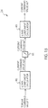
- a modified example 4 of the current command value calculator 24 not forming part of the invention will be described while referring to Fig. 13 .
- one current command value is corrected to calculate the current command values with which the output voltage becomes equal to or more than the target value V SET , in a similar manner to the modified example 3.
- the correction value ⁇ iq* is generated by the corrector 47, and the correction value ⁇ iq* is added to the current command value iq3* in the adder 48, to thereby generate the current command value iqc*.
- a lower limit of the current command value iq3* is limited by a lower-limit limiter 91, to thereby generate the current command value iqc*.
- the lower-limit limiter 91 corrects (limits) the iq3* so that the iqc* becomes equal to or more than the iq SET , as illustrated in Fig. 9 .
- Fig. 14 is a diagram illustrating a configuration of a system according to the present embodiment. As illustrated in Fig. 14 , the controller 2 according to the present embodiment further includes a torque command value calculator 29. The other configurations are similar to those of the first embodiment.
- the torque command value calculator (speed controller) 29 calculates the torque command value T* based on a speed command value ⁇ * and the estimated speed ⁇ est.
- the speed command value ⁇ * indicates an angular speed of rotating the rotor of the SynRM1.
- the torque command value T* calculated by the torque command value calculator 29 is input into the current command value calculator 24. Note that in the present embodiment, it is set that the speed command value ⁇ * is input from an external device.
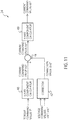
- Fig. 15 is a diagram illustrating a configuration of the torque command value calculator 29. As illustrated in Fig. 15 , the torque command value calculator 29 includes a subtracter 71, and a PI controller 72.
- the speed command value ⁇ * and the estimated speed ⁇ est are input into the subtracter 71.
- the subtracter 71 subtracts the estimated speed ⁇ est from the speed command value ⁇ *, to thereby calculate an error ⁇ of the angular speed of the rotor.
- the error ⁇ calculated by the subtracter 71 is input into the PI controller 72.
- the PI controller 72 performs PI control based on the error ⁇ , and calculates the torque command value T* with which the error ⁇ becomes 0.
- the torque command value T* calculated by the PI controller 72 is input into the current command value calculator 24.
- Fig. 16 is a diagram illustrating another configuration of the current command value calculator 24 in an example not forming part of the invention.
- the current command value calculator 24 calculates the current command values idc*, iqc*, based on the torque command value T* and a phase angle command value ⁇ *.
- the current command value calculator 24 includes an output voltage calculator 81, a subtracter 82, a limiter 83, a PI controller 84, a phase angle command value calculator 85, a subtracter 86, and a current command value obtainer 87.
- the voltage command values vdc*, vqc* calculated by the voltage command value calculator 25 are input into the output voltage calculator 81.
- the output voltage calculator 81 calculates the output voltage V 1 of the SynRM1, based on the voltage command values vdc*, vqc*.
- the output voltage V 1 calculated by the output voltage calculator 81 is input into the subtracter 82.
- the subtracter 82 subtracts the output voltage V 1 from the target value V SET of the output voltage, to thereby calculate an error ⁇ V of the output voltage.
- the error ⁇ V calculated by the subtracter 82 is input into the limiter 83.
- the limiter 83 limits the error ⁇ V to 0 or more. Namely, the limiter 83 outputs only the error ⁇ V of 0 or more.
- the error ⁇ V output by the limiter 83 is input into the PI controller 84.
- the PI controller 84 performs PI control based on the error ⁇ V which is limited to 0 or more, to thereby calculate a correction value ⁇ * with which the output voltage V 1 of the SynRM1 becomes equal to or more than the target value V SET .
- the correction value ⁇ * is a phase angle command value for calculating the phase angle command value ⁇ * by correcting the phase angle command value ⁇ 1*.
- the correction value ⁇ * calculated by the PI controller 84 is input into the subtracter 86.
- the phase angle command value calculator 85 calculates the phase angle command value ⁇ 1* based on the torque command value T*.
- the phase angle command value ⁇ 1* is a value before correction of the phase angle command value ⁇ *.
- the phase angle command value ⁇ 1* is calculated by any method in accordance with control desired to be realized by the controller, so that the torque of the SynRM1 becomes the torque command value T*.
- the phase angle command value calculator 85 calculates the phase angle command value ⁇ 1* so that a magnitude of the current which is flowed through the stator becomes minimum.
- the phase angle command value calculator 85 may also set the phase angle command value ⁇ 1* to 135 degrees, by ignoring magnetic saturation, or it may also set the phase angle command value ⁇ 1* to a degree larger than 135 degrees, by taking the magnetic saturation into consideration.
- the phase angle command value calculator 85 may also calculate the phase angle command value ⁇ 1* so that the efficiency and the power factor of the SynRM1 become maximum.
- phase angle command value ⁇ 1* calculated by the phase angle command value calculator 85 is input into the subtracter 86.
- the subtracter 86 subtracts the correction value ⁇ * from the phase angle command value ⁇ 1*, to thereby calculate the phase angle command value ⁇ *.
- the phase angle command value ⁇ * calculated by the subtracter 86 is input into the current command value obtainer 87.
- the current command value obtainer 87 calculates the current command values idc*, iqc*, based on the torque command value T* and the phase angle command value ⁇ *. Concretely, the current command value obtainer 87 is only required to obtain coordinates of a point, on the equal torque curve of the toque command value T*, at which the current phase angle becomes the phase angle command value ⁇ *.
- the current command values idc*, iqc* obtained by the current command value obtainer 87 are input into the voltage command value calculator 25.
- the current command value calculator 24 in Fig. 16 corrects the current phase angle so that the output voltage V 1 becomes equal to or more than the target value V SET .
- the current command value calculator 24 corrects the current phase angle in a delay direction so that the current command values are shifted to the q axis side. Consequently, it is possible to make the output voltage V 1 under the low load to be equal to or more than the target value V SET .
- the required accuracy of torque control with respect to the controller 2 according to the present embodiment is lower than that with respect to the first embodiment. This is because the controller 2 according to the present embodiment performs control to make the speed ⁇ of the SynRM1 to be the speed command value ⁇ *.
- the current command value calculator 24 can calculate the current command values without using a table for correctly controlling the torque of the SynRM1 (a table in which the output voltage for each of the current command values is stored, or the like).
- 1 synchronous reluctance motor (SynRM), 2: inverter controller, 21: inverter, 22: current detector, 23: coordinate transformer, 24: current command value calculator, 25: voltage command value calculator, 26: coordinate transformer, 27: PWM modulator, 28: speed and rotational phase angle estimator, 29: torque command value calculator, 31: phase difference ⁇ setter, 32: ⁇ voltage calculator, 33: ⁇ voltage estimator, 34: subtracter, 35: PI controller, 36: integrator, 41: first calculator, 42: second calculator, 43: selector, 44: q axis component calculator, 45: d axis component calculator, 46: q axis component calculator, 47: corrector, 48: adder, 49: d axis component calculator, 51: first current vector, 52: second current vector, 53: equal torque curve, 54: equal voltage ellipse, 61: output voltage calculator, 62: subtracter, 63: limiter, 64: PI controller, 71: subtracter, 72: PI controller, 81
Description
- Embodiments of the present invention relate to an inverter controller and a motor driving system.
- Conventionally, there has been used an estimation method of a rotational phase angle utilizing an induced voltage in a high-speed range in a rotational phase angle sensorless controller of a permanent magnet synchronous motor (PMSM) and a synchronous reluctance motor (SynRM). However, in the SynRM and the PMSM having small magnetic flux, even in the high-speed range, the induced voltage is small under a state of low load, so that there has been a problem that estimation accuracy of the rotational phase angle deteriorates.
-
- Patent Document 1:
Japanese Patent Laid-Open Publication No. 2003-250293 - Patent Document 2:
Japanese Patent Laid-Open Publication No. 2006-074902 JP2010-136586 claim 1. - An inverter controller and a motor driving system capable of estimating, with good accuracy, a rotational phase angle of a motor under a state of high speed and low load, are provided.
- The present invention is defined in the
independent claim 1 with preferred embodiments disclosed in the dependent claims. -
-
Fig. 1 is a diagram illustrating a configuration of a motor driving system according to a first embodiment; -
Fig. 2 is a diagram explaining a three-phase fixed coordinate system and a rotating coordinate system of dc and qc axes; -
Fig. 3 is a diagram illustrating a configuration of a speed and rotational phase angle estimator inFig. 1 ; -
Fig. 4 is a diagram illustrating a configuration of a current command value calculator inFig. 1 ; -
Fig. 5 is a diagram explaining a calculation method of current command values; -
Fig. 6 is a diagram illustrating a relationship between a torque command value T* and an output voltage in a controller inFig. 1 ; -
Fig. 7 is a diagram illustrating a configuration of a modified example 1 of the current command value calculator; -
Fig. 8 is a diagram illustrating a configuration of a modified example 2 of the current command value calculator not forming part of the invention. -
Fig. 9 is a diagram explaining a calculation method of a current command value in the modified example 2; -
Fig. 10 is a diagram explaining a calculation method of the current command value in the modified example 2; -
Fig. 11 is a diagram illustrating a configuration of a modified example 3 of the current command value calculator not forming part of the invention. -
Fig. 12 is a diagram illustrating a configuration of a corrector; -
Fig. 13 is a diagram illustrating a configuration of a modified example 4 of the current command value calculator not forming part of the invention. -
Fig. 14 is a diagram illustrating a configuration of a motor driving system according to a second embodiment; -
Fig. 15 is a diagram illustrating a configuration of a torque command value calculator inFig. 14 ; and -
Fig. 16 is a diagram illustrating a configuration of a the invention. - Hereinafter, embodiments of the present invention will be described with reference to the drawings.
- A motor driving system (which is referred to as "system", hereinafter) according to a first embodiment will be described with reference to
Fig. 1 to Fig. 13 .Fig. 1 is a diagram illustrating a configuration of the system according to the present embodiment. As illustrated inFig. 1 , the system according to the present embodiment includes amotor 1 and aninverter controller 2. - The
motor 1 is a rotary drive target of thecontroller 2, and is connected to thecontroller 2. Hereinafter, explanation will be made by citing a case where themotor 1 is a synchronous reluctance motor (which is referred to as "SynRM1", hereinafter), as an example. The SynRM1 includes a stator and a rotor. The stator has three excitation phases (U phase, V phase, and W phase). The stator generates a magnetic field with the use of a three-phase alternating current which flows through each excitation phase. The rotor does not have a permanent magnet. The rotor is rotated through a magnetic interaction with the magnetic field generated by the stator. - The inverter controller 2 (which is referred to as "
controller 2", hereinafter) controls a rotational phase angle of the SynRM1 in a sensorless manner. As illustrated inFig. 1 , thecontroller 2 according to the present embodiment includes aninverter 21,current detectors 22, acoordinate transformer 23, a currentcommand value calculator 24, a voltagecommand value calculator 25, acoordinate transformer 26, aPWM modulator 27, and a speed and rotationalphase angle estimator 28. - The
inverter 21 is a circuit including switching elements (transistors). Theinverter 21 switches ON/OFF of the switching elements to convert power from a power source (whose illustration is omitted) into alternating-current power, and supplies it to the SynRM1. A control signal for controlling ON/OFF of the respective switching elements is input into theinverter 21 from thePWM modulator 27. - The
current detectors 22 detect current values of two phases or three phases, in the three-phase alternating current flowing through the stator of the SynRM1.Fig. 1 illustrates a configuration in which current values iu, iw of two phases (U phase and W phase) are detected. - The
coordinate transformer 23 performs coordinate transformation on the current values iu, iw detected by thecurrent detectors 22, from a three-phase fixed coordinate system to a rotating coordinate system of dc and qc axes. Here, the three-phase fixed coordinate system and the rotating coordinate system of dc and qc axes will be described with reference toFig. 2 . - As illustrated in
Fig. 2 , the three-phase fixed coordinate system is a fixed coordinate system formed of an α axis and a β axis. InFig. 2 , the α axis is set in the U phase direction, and the β axis is set in a direction perpendicular to the α axis. The current values iu, iw detected by thecurrent detectors 22 are represented on the three-phase fixed coordinates as described above. - On the contrary, the rotating coordinate system of dc and qc axes is a rotating coordinate system formed of a dc axis and a qc axis. The dc axis is set in a direction which is estimated by the
controller 2 as a d axis direction (a direction in which an inductance of the rotor is minimum), and the qc axis is set in a direction which is estimated by thecontroller 2 as a q axis direction (a direction in which the inductance of the rotor is maximum). An inductance ellipse inFig. 2 indicates an inductance of the rotor. - As illustrated in
Fig. 2 , the dc and qc axes, and the d and q axes do not always coincide. An actual rotational phase angle θ of the rotor is represented by an angle from the α axis to the d axis. Further, an estimated rotational phase angle θest of the rotor estimated by thecontroller 2 is represented by an angle from the α axis to the dc axis. It is indicated that the closer the angle between the rotational phase angle θ and the estimated rotational phase angle θest, the higher the estimation accuracy of the rotational phase angle. - The
coordinate transformer 23 can transform the three-phase fixed coordinate system into the rotating coordinate system of dc and qc axes, by using the estimated rotational phase angle θest output by the speed and rotationalphase angle estimator 28. Hereinafter, values obtained when thecoordinate transformer 23 performs the coordinate transformation on the current values iu, iw are referred to as current values idc, iqc. The current value idc is a dc axis component of the current which flows through the stator, and the current value iqc is a qc axis component of the current which flows through the stator. - The current
command value calculator 24 calculates current command values idc*, iqc*, based on a torque command value T* and an estimated speed ωest. The torque command value T* is a value of torque generated in the rotor. In the present embodiment, it is set that the torque command value T* is input from an external device. The estimated speed ωest indicates an angular speed of the rotor estimated by thecontroller 2. The current command value idc* is a dc axis component of the current which is flowed through the SynRM1. The current command value iqc* is a qc axis component of the current which is flowed through the SynRM1. Details of the currentcommand value calculator 24 will be described later. - The voltage command value calculator 25 (current controller) calculates voltage command values vdc*, vqc* with which the current values idc, iqc of the SynRM1 become equal to the current command values idc*, iqc*. The voltage command value vdc* is a dc axis component of a voltage applied to the stator of the SynRM1. The voltage command value vqc* is a qc axis component of the voltage applied to the stator of the SynRM1.
- The coordinate
transformer 26 performs coordinate transformation on the voltage command values vdc*, vqc* output by the voltagecommand value calculator 25, from the rotating coordinate system of dc and qc axes to the three-phase fixed coordinate system. The coordinatetransformer 26 can transform the rotating coordinate system of dc and qc axes into the three-phase fixed coordinate system by using the estimated rotational phase angle θest, in a similar manner to the coordinatetransformer 23. Hereinafter, values obtained when the coordinatetransformer 26 performs the coordinate transformation on the voltage command values vdc*, vqc*, are referred to as voltage command values vu*, vv*, vw*. The voltage command value vu* is a voltage applied to the U phase of the stator, the voltage command value vv* is a voltage applied to the V phase of the stator, and the voltage command value vw* is a voltage applied to the W phase of the stator. - The
PWM modulator 27 modulates the voltage command values vu*, vv*, vw* through PWM (Pulse-Width Modulation) using a triangular wave, and generates a binary control signal corresponding to ON or OFF of each of the switching elements of theinverter 21. ThePWM modulator 27 inputs the generated control signal into theinverter 21. - The speed and rotational phase angle estimator 28 (which is referred to as "
estimator 28", hereinafter) estimates a speed co and a rotational phase angle θ of the rotor of the SynRM1, based on the torque command value T*, the voltage command values vdc*, vqc*, and the current values idc, iqc, and calculates the estimated speed coest and the estimated rotational phase angle θest. -
Fig. 3 is a diagram illustrating a configuration of theestimator 28. As illustrated inFig. 3 , theestimator 28 includes a phase difference δsetter 31, aγ voltage calculator 32, aγ voltage estimator 33, asubtracter 34, aPI controller 35, and anintegrator 36. - The phase difference δ
setter 31 outputs a phase difference δ in accordance with the torque command value T*, from previously stored plural phase differences δ. The phase difference δ indicates a value or a range of phase difference which causes the largest voltage variation due to influence of an error Δθ between the rotational phase angle θ and the estimated rotational phase angle θest. The plural phase differences δ are previously calculated in an analytic manner or experimental manner for each torque value, and stored in the phase difference δsetter 31. - The
γ voltage calculator 32 calculates a voltage value vy of a γ voltage, based on the voltage command values vdc*, vqc*, and the phase difference δ set (output) by the phase difference δsetter 31. The γ voltage is a feature amount which varies in accordance with the error Δθ. The voltage value vy is calculated through the following expression, for example.
[Mathematical expression 1]
- The voltage value vy calculated by the
γ voltage calculator 32 is input into thesubtracter 34. - The
γ voltage estimator 33 calculates an estimated voltage value vyest of the γ voltage, based on voltage values vdcest, vqcest, and the phase difference δ set (output) by the phase difference δsetter 31. - First, the
γ voltage estimator 33 calculates the voltage values vdcest, vqcest, based on the current values idc, iqc, and the estimated speed ωest. The voltage value vdcest is an estimated value of the dc axis component of the voltage applied to the stator of the SynRM1. The voltage value vqcest is an estimated value of the qc axis component of the voltage applied to the stator of the SynRM1. The voltage values vdcest, vqcest are calculated through the following expression.
[Mathematical expression 2]
- In the expression (2), Rm indicates a winding resistance of the stator, Ld indicates an inductance in the d axis direction, Lq indicates an inductance in the q axis direction, and p indicates a differential operator (d/dt). The
γ voltage estimator 33 previously stores these values. - Next, the
γ voltage estimator 33 calculates the estimated voltage value vyest of the γ voltage, based on the voltage values vdcest, vqcest, and the phase difference δ. The estimated voltage value vyest is calculated through the following expression, for example.
[Mathematical expression 3]
- The estimated voltage value vyest calculated by the
γ voltage estimator 33 is input into thesubtracter 34. - The
subtracter 34 subtracts the voltage value vy from the estimated voltage value vyest to calculate an error Δvγ of the γ voltage. The γ voltage varies in accordance with the error Δθ, so that the error Δvγ is in proportion to the error Δθ. The error Δvγ calculated by thesubtracter 34 is input into thePI controller 35. - Note that by calculating the γ voltage through the expression (1), it is possible to improve linearity of the error Δvγ with respect to the error Δθ. Specifically, it is possible to enlarge a range of the error Δθ to which the error Δvγ is in proportion.
- The
PI controller 35 performs PI control to make the error Δvγ become 0, to thereby estimate the speed ω of the rotor and calculate the estimated speed ωest. The estimated speed ωest calculated by thePI controller 35 is sequentially fed back to theγ voltage estimator 33, and is also input into theintegrator 36. - The
integrator 36 integrates the estimated speed ωest calculated by thePI controller 35, and calculates the estimated rotational phase angle θest. - Through the configuration as described above, the
estimator 28 can calculate the estimated speed ωest and the estimated rotational phase angle θest. The estimated speed ωest calculated by theestimator 28 is input into the currentcommand value calculator 24. Further, the estimated rotational phase angle θest is input into the coordinatetransformers - Note that the estimation method of the speed ω and the rotational phase angle θ performed by the
estimator 28 is not limited to this, and any method can be selected from already-known estimation methods. For example, theestimator 28 may also estimate the rotational phase angle θ based on another method which uses a voltage generated by an interlinkage magnetic flux, it may also estimate the rotational phase angle θ by using the interlinkage magnetic flux itself, or it may also estimate the rotational phase angle θ by performing PI control so that a deviation of the q axis component of the current value becomes 0. - Here, the current
command value calculator 24 will be described in detail. The currentcommand value calculator 24 according to the present embodiment calculates current command values so that an output voltage of the SynRM1 becomes equal to or more than a predetermined target value VSET. The target value VSET is a voltage value previously determined in an experimental manner or analytic manner, as an output voltage capable of accurately estimating the speed ω and the rotational phase angle θ. - Here,
Fig. 4 is a diagram illustrating the configuration of the currentcommand value calculator 24. As illustrated inFig. 4 , the currentcommand value calculator 24 includes afirst calculator 41, asecond calculator 42, and aselector 43. - The
first calculator 41 generates first current command values id1*, iq1*, based on the torque command value T*. The first current command value id1* is a dc axis component of the current which is flowed through the SynRM1. The first current command value iq1* is a qc axis component of the current which is flowed through the SynRM1. Thefirst calculator 41 calculates the first current command values id1*, iq1*, so that a torque of the SynRM1 becomes the torque command value T*. -
Fig. 5 is a diagram explaining a calculation method of the current command values. InFig. 5 , a horizontal axis indicates idc, a vertical axis indicates iqc, anarrow mark 51 indicates a first current vector, anarrow mark 52 indicates a second current vector, acurve 53 indicates an equal torque curve of the torque command value T*, and acurve 54 indicates an equal voltage ellipse of the target value VSET. - The first
current vector 51 is a vector corresponding to the first current command values id1*, iq1*. In the above description, the first current command values are represented by two values of (id1*, iq1*), but, they can also be represented by a magnitude of current (id1*2+iq1*2)1/2 and a current phase angle β1. These representations can be mutually converted. The selection of any point on a plane inFig. 5 corresponds to calculation (selection) of the first current command values. - As illustrated in
Fig. 5 , thefirst calculator 41 selects any point on theequal torque curve 53 of the torque command value T*, as the first current command values. Thefirst calculator 41 can select the first current command values from a position on theequal torque curve 53, based on any method in accordance with control desired to be realized by thecontroller 2. - For example, the
first calculator 41 selects the first current command values so that a magnitude of the current which is flowed through the stator (a magnitude of the first current vector) becomes minimum. In this case, thefirst calculator 41 may also select the first current command values with which the current phase angle β1 becomes 135 degrees, by ignoring magnetic saturation, or it may also select the first current command values with which the current phase angle β1 becomes a degree larger than 135 degrees, by taking the magnetic saturation into consideration. Further, thefirst calculator 41 may also select the first current command values so that efficiency and a power factor of the SynRM1 become maximum. - The
first calculator 41 may also select the first current command values as described above by referring to a table in which the first current command values for each torque value are stored, or it may also determine the first current command values as described above by calculation. The first current command values calculated by thefirst calculator 41 are input into theselector 43. - The
second calculator 42 calculates second current command values id2*, iq2*, based on the torque command value T* and the estimated speed ωest. The second current command value id2* is a dc axis component of the current which is flowed through the SynRM1. The second current command value iq2* is a qc axis component of the current which is flowed through the SynRM1. Thesecond calculator 42 calculates the second current command values id2*, iq2*, so that the torque of the SynRM1 becomes the torque command value T* and the output voltage of the SynRM1 becomes the target value VSET. - The second
current vector 52 inFig. 5 is a vector corresponding to the second current command values id2*, iq2*. In the above description, the second current command values are represented by two values of (id2*, iq2*), but, they can also be represented by a magnitude of current (id2*2+iq2*2)1/2 and a current phase angle β2. These representations can be mutually converted. The selection of any point on the plane inFig. 5 corresponds to calculation (selection) of the second current command values. - As illustrated in
Fig. 5 , thesecond calculator 42 selects, as the second current command values, any one of intersection points between theequal torque curve 53 of the torque command value T* and theequal voltage ellipse 54 of the target value VSET. When there are two intersection points A, B, it is preferable that thesecond calculator 42 selects the intersection point A, as illustrated inFig. 5 . - The intersection point A indicates an intersection point on the iqc axis side (on the q axis side), between the two intersection points. Generally, the
equal voltage ellipse 54 becomes wide in the d axis direction and becomes narrow in the q axis direction, so that if the intersection point A on the q axis side is selected, a magnitude of the current which is flowed through the stator (a magnitude of the second current vector) becomes small, when compared to a case where the intersection point B on the d axis side is selected. For this reason, when thesecond calculator 42 selects the intersection point A, it is possible to save power of thecontroller 2. Hereinafter, it is set that the second current command values correspond to the intersection point A. - Note that the
second calculator 42 may also select the second current command values as described above by referring to a table in which the second current command values for each torque value are stored, or it may also determine the second current command values as described above by solving the following expression.
[Mathematical expression 4]
- The second current command values calculated by the
second calculator 42 are input into theselector 43. - The
selector 43 outputs the first current command values id1*, iq1* or the second current command values id2*, iq2*, as the current command values idc*, iqc*. First, theselector 43 determines whether or not an output voltage V1 in accordance with the first current command values id1*, iq1* is lower than the target value VSET. The output voltage V1 indicates an output voltage of the SynRM1 when the first current command values are output as the current command values. The determination method will be described later. - Next, the
selector 43 selects either of the first current command values id1*, iq1* or the second current command values id2*, iq2*, in accordance with the determination result, and outputs the selected values as the current command values idc*, iqc*. - When the output voltage V1 is lower than the target value VSET (V1<VSET), the
selector 43 selects the second current command values id2*, iq2* as the current command values idc*, iqc*. The case where the output voltage V1 is lower than the target value VSET, indicates a case where the first current command values are included in theequal voltage ellipse 54, as illustrated inFig. 5 . - At this time, the second current command values are closer to the iqc axis (q axis) than the first current command values. Specifically, a current phase angle β2 of the second current command values is further on the iqc axis (q axis) side than the current phase angle β1 of the first current command values. Further, the q axis component iq2* of the second current command value is larger than the q axis component iq1* of the first current command value, and the d axis component id2* of the second current command value is smaller than the d axis component id1* of the first current command value.
- On the other hand, when the output voltage V1 is equal to or more than the target value VSET (V1≥VSET), the
selector 43 selects the first current command values id1*, iq1* as the current command values idc*, iqc*. The case where the output voltage V1 is equal to or more than the target value VSET, indicates a case where the second current command values are on theequal voltage ellipse 54 or outside of theequal voltage ellipse 54. - At this time, the first current command values are closer to the iqc axis (q axis) than the second current command values. Specifically, the current phase angle β1 of the first current command values is further on the iqc axis (q axis) side than the current phase angle β2 of the second current command values. Further, the q axis component iq1* of the first current command value is larger than the q axis component iq2* of the second current command value, and the d axis component id1* of the first current command value is smaller than the d axis component id2* of the second current command value.
- The
selector 43 outputs the selected first current command values or second current command values as the current command values. The current command values output by theselector 43 are input into the voltagecommand value calculator 25. - Next, description will be made on the determination method performed by the
selector 43, regarding whether or not the output voltage V1 is lower than the target value VSET. - The
selector 43 obtains the output voltage V1, and performs determination by comparing the output voltage V1 with the target value VSET, for example. Theselector 43 may also select the output voltage V1 by referring to a table in which the output voltage for each of the first current command values is stored, or it may also calculate the output voltage V1 through the following expression.
[Mathematical expression 5]
- Further, it is also possible that the
selector 43 performs the determination by comparing the current phase angle β1 of the first current command values with the current phase angle β2 of the second current command values. When the current phase angle β2 is further on the q axis side than the current phase angle β1, theselector 43 determines that the output voltage V1 is lower than the target value VSET. - In an example not forming part of the invention, it is also possible that the
selector 43 performs the determination by comparing the q axis component iq1* of the first current command value with the q axis component iq2* of the second current command value. When the q axis component iq1* is smaller than the q axis component iq2*, theselector 43 determines that the output voltage V1 is lower than the target value VSET. - In addition, it is also possible that the
selector 43 performs the determination by comparing the d axis component id1* of the first current command value with the d axis component id2* of the second current command value. When the d axis component id1* is larger than the d axis component id2*, theselector 43 determines that the output voltage V1 is lower than the target value VSET. - When the current
command value calculator 24 calculates the current command values idc*, iqc*, as described above, it is possible to set the output voltage of the SynRM1 to be equal to or more than the target value VSET with respect to any torque command value T*, as indicated by a solid line inFig. 6 . - In the conventional controller, even if the SynRM1 operates in a high-speed range, the output voltage (induced voltage) of the SynRM1 becomes small, as indicated by a dotted line in
Fig. 6 , in a state of low load in which the torque command value T* is small. For this reason, it has been difficult to estimate the speed ω and the rotational phase angle θ with good accuracy by utilizing the induced voltage. - However, the
controller 2 according to the present embodiment can set the output voltage to be equal to or more than the target value VSET even in the case of low load, so that it can estimate the speed ω and the rotational phase angle θ of the SynRM1 with good accuracy based on the output voltage of the SynRM1. - Note that in the above description, the case where the
controller 2 controls the operation of the SynRM1 is explained, but, thiscontroller 2 can also be used as a controller of a PMSM with small magnetic flux. The PMSM with small magnetic flux has small induced voltage under a low load, similarly to the SynRM1. By applying thecontroller 2 according to the present embodiment to such a PMSM, it is possible to improve the estimation accuracy of the speed ω and the rotational phase angle θ of the PMSM under the low load. - A modified example 1 of the current
command value calculator 24 according to the present embodiment will be described while referring toFig. 7. Fig. 7 is a diagram illustrating a configuration of the modified example 1 of the currentcommand value calculator 24. As illustrated inFig. 7 , thesecond calculator 42 includes a qaxis component calculator 44 and a daxis component calculator 45. The other configurations of the currentcommand value calculator 24 are similar to those inFig. 4 . - The q
axis component calculator 44 calculates the q axis component iq2* of the second current command value based on the estimated speed ωest. Concretely, the qaxis component calculator 44 calculates the q axis component iq2* to make the current value iq2* to be in inverse proportion to the estimated speed ωest. The q axis component iq2* is calculated through the following expression, for example.
[Mathematical expression 6]
- The d
axis component calculator 45 calculates the d axis component id2* of the second current command value based on the torque command value T* and the q axis component iq2*. The d axis component id2* is calculated through the following expression, for example.
[Mathematical expression 7]
- Through the configuration as described above, the
controller 2 can set the output voltage under the low load to be equal to or more than the target value VSET. Further, it is possible to suppress a current loss in a high-speed range. - A modified example 2 of the current
command value calculator 24 will be described while referring toFig. 8 to Fig. 10. Fig. 8 is a diagram illustrating a configuration of the modified example 2 of the currentcommand value calculator 24 not forming part of the invention. As illustrated inFig. 8 , the currentcommand value calculator 24 calculates the current command values iqc*, idc*, based on the torque command value T* and the estimated speed ωest. - In the present modified example, the current
command value calculator 24 calculates the q axis component iqc* of the current command value so that the q axis component iqc* becomes equal to or more than a predetermined target value iqSET, as illustrated inFig. 9 . Further, the currentcommand value calculator 24 generates the q axis component iqc* so that the target value iqSET becomes small as the estimated speed ωest increases, as illustrated inFig. 10 . - Through the configuration as described above, it is possible to set the output voltage of motor under the low load to be equal to or more than the target value VSET. Further, it is possible to suppress the current loss in the high-speed range.
- A modified example 3 of the current
command value calculator 24 not forming part of the invention will be described while referring toFig. 11 andFig. 12 . The currentcommand value calculator 24 described above selects one of the two sets of current command values to calculate the current command values with which the output voltage becomes equal to or more than the target value VSET. On the contrary, in the present modified example, one current command value is corrected to calculate the current command values with which the output voltage becomes equal to or more than the target value VSET. -
Fig. 11 is a diagram illustrating a configuration of the modified example 3 of the currentcommand value calculator 24. As illustrated inFig. 11 , the currentcommand value calculator 24 includes a qaxis component calculator 46, acorrector 47, anadder 48, and a daxis component calculator 49. - The q
axis component calculator 46 calculates a current command value iq3* based on the torque command value T*. The current command value iq3* is a value before correction of the q axis component of the current command value. The currentcommand value calculator 24 in the present modified example corrects the current command value iq3*, thereby calculating the q axis component of the current command value. The current command value iq3* is calculated by any method in accordance with control desired to be realized by the controller, so that the torque of the SynRM1 becomes the torque command value T*. - For example, the q
axis component calculator 46 calculates the current command value iq3* so that a magnitude of the current which is flowed through the stator becomes minimum. In this case, the qaxis component calculator 46 may also calculate the current command value iq3* with which the current phase angle β becomes 135 degrees, by ignoring magnetic saturation, or it may also calculate the current command value iq3* with which the current phase angle β becomes a degree larger than 135 degrees, by taking the magnetic saturation into consideration. Further, the qaxis component calculator 46 may also calculate the current command value iq3* so that the efficiency and the power factor of the SynRM1 become maximum. - The current command value iq3* calculated by the q
axis component calculator 46 is input into theadder 48. - The voltage command values vdc*, vqc* are input into the
corrector 47 from the voltagecommand value calculator 25. Thecorrector 47 calculates a correction value Δiq*, based on the voltage command values vdc*, vqc*. The correction value Δiq* is a current command value for calculating the q axis component iqc* of the current command value by correcting the current command value iq3*. Details of thecorrector 47 will be described later. The correction value Δiq* calculated by thecorrector 47 is input into theadder 48. - The
adder 48 adds the correction value Δiq* to the current command value iq3*, to thereby calculate the current command value iqc*. The current command value iqc* calculated by theadder 48 is input into the daxis component calculator 49. - The d
axis component calculator 49 calculates the d axis component idc* of the current command value based on the torque command value T* and the current command value iqc*, so that the torque of the SynRM1 becomes the torque command value T*. The d axis component idc* is calculated through the following expression, for example.
[Mathematical expression 8]
- Here, the
corrector 47 will be described with reference toFig. 12. Fig. 12 is a diagram illustrating a configuration of thecorrector 47. As illustrated inFig. 12 , thecorrector 47 includes anoutput voltage calculator 61, asubtracter 62, alimiter 63, and aPI controller 64. - The voltage command values vdc*, vqc* calculated by the voltage
command value calculator 25 are input into theoutput voltage calculator 61. Theoutput voltage calculator 61 calculates the output voltage V1 of the SynRM1, based on the voltage command values vdc*, vqc*. The output voltage V1 is calculated through the following expression, for example.
[Mathematical expression 9]
- The output voltage V1 calculated by the
output voltage calculator 61 is input into thesubtracter 62. - The
subtracter 62 subtracts the output voltage V1 from the target value VSET of the output voltage, thereby calculating an error ΔV of the output voltage. The error ΔV calculated by thesubtracter 62 is input into thelimiter 63. - The
limiter 63 limits the error ΔV to 0 or more. Namely, thelimiter 63 outputs only the error ΔV of 0 or more. The error ΔV output by thelimiter 63 is input into thePI controller 64. - The
PI controller 64 performs PI control based on the error ΔV which is limited to 0 or more, to thereby calculate the correction value Δiq* with which the output voltage V1 of the SynRM1 becomes equal to or more than the target value VSET. The correction value Δiq* calculated by thePI controller 64 is input into theadder 48. - Through the configuration as described above, when the output voltage V1 in accordance with the current command values is lower than the target value VSET, namely, when ΔV is 0 or more, the correction value Δiq* is added to the current command value as an offset current to make the output voltage V1 to be equal to or more than the target value VSET. Consequently, it is possible to set the output voltage V1 under the low load to be equal to or more than the target value VSET.
- A modified example 4 of the current
command value calculator 24 not forming part of the invention will be described while referring toFig. 13 . In the present modified example, one current command value is corrected to calculate the current command values with which the output voltage becomes equal to or more than the target value VSET, in a similar manner to the modified example 3. In the modified example 3, the correction value Δiq* is generated by thecorrector 47, and the correction value Δiq* is added to the current command value iq3* in theadder 48, to thereby generate the current command value iqc*. On the contrary, in the present modified example, a lower limit of the current command value iq3* is limited by a lower-limit limiter 91, to thereby generate the current command value iqc*. - The lower-
limit limiter 91 corrects (limits) the iq3* so that the iqc* becomes equal to or more than the iqSET, as illustrated inFig. 9 . The iqSET is calculated from a minimum speed ωMIN when the present example is used, for example, and the target value VSET of the output voltage, through the following expression.
[Mathematical expression 10]
- Through the configuration as described above, it is possible to set the output voltage V1 to be equal to or more than the target value VSET, even under the low load. In the present modified example, it is possible to set the output voltage V1 to be equal to or more than the target value VSET, with the simple configuration realized by only adding the lower-
limit limiter 91 to the first embodiment and each of the modified examples 1 to 3. - Next, a
controller 2 according to a second embodiment will be described while referring toFig. 14 to Fig. 16 .Fig. 14 is a diagram illustrating a configuration of a system according to the present embodiment. As illustrated inFig. 14 , thecontroller 2 according to the present embodiment further includes a torquecommand value calculator 29. The other configurations are similar to those of the first embodiment. - The torque command value calculator (speed controller) 29 calculates the torque command value T* based on a speed command value ω* and the estimated speed ωest. The speed command value ω* indicates an angular speed of rotating the rotor of the SynRM1. In the present embodiment, the torque command value T* calculated by the torque
command value calculator 29 is input into the currentcommand value calculator 24. Note that in the present embodiment, it is set that the speed command value ω* is input from an external device. -
Fig. 15 is a diagram illustrating a configuration of the torquecommand value calculator 29. As illustrated inFig. 15 , the torquecommand value calculator 29 includes asubtracter 71, and aPI controller 72. - The speed command value ω* and the estimated speed ωest are input into the
subtracter 71. Thesubtracter 71 subtracts the estimated speed ωest from the speed command value ω*, to thereby calculate an error Δω of the angular speed of the rotor. The error Δω calculated by thesubtracter 71 is input into thePI controller 72. - The
PI controller 72 performs PI control based on the error Δω, and calculates the torque command value T* with which the error Δω becomes 0. The torque command value T* calculated by thePI controller 72 is input into the currentcommand value calculator 24. -
Fig. 16 is a diagram illustrating another configuration of the currentcommand value calculator 24 in an example not forming part of the invention. The currentcommand value calculator 24 calculates the current command values idc*, iqc*, based on the torque command value T* and a phase angle command value β*. - As illustrated in
Fig. 16 , the currentcommand value calculator 24 includes anoutput voltage calculator 81, asubtracter 82, alimiter 83, aPI controller 84, a phase anglecommand value calculator 85, asubtracter 86, and a currentcommand value obtainer 87. - The voltage command values vdc*, vqc* calculated by the voltage
command value calculator 25 are input into theoutput voltage calculator 81. Theoutput voltage calculator 81 calculates the output voltage V1 of the SynRM1, based on the voltage command values vdc*, vqc*. The output voltage V1 calculated by theoutput voltage calculator 81 is input into thesubtracter 82. - The
subtracter 82 subtracts the output voltage V1 from the target value VSET of the output voltage, to thereby calculate an error ΔV of the output voltage. The error ΔV calculated by thesubtracter 82 is input into thelimiter 83. - The
limiter 83 limits the error ΔV to 0 or more. Namely, thelimiter 83 outputs only the error ΔV of 0 or more. The error ΔV output by thelimiter 83 is input into thePI controller 84. - The
PI controller 84 performs PI control based on the error ΔV which is limited to 0 or more, to thereby calculate a correction value Δβ* with which the output voltage V1 of the SynRM1 becomes equal to or more than the target value VSET. The correction value Δβ* is a phase angle command value for calculating the phase angle command value β* by correcting the phase angle command value β1*. The correction value Δβ* calculated by thePI controller 84 is input into thesubtracter 86. - The phase angle
command value calculator 85 calculates the phase angle command value β1* based on the torque command value T*. The phase angle command value β1* is a value before correction of the phase angle command value β*. The phase angle command value β1* is calculated by any method in accordance with control desired to be realized by the controller, so that the torque of the SynRM1 becomes the torque command value T*. - For example, the phase angle
command value calculator 85 calculates the phase angle command value β1* so that a magnitude of the current which is flowed through the stator becomes minimum. In this case, the phase anglecommand value calculator 85 may also set the phase angle command value β1* to 135 degrees, by ignoring magnetic saturation, or it may also set the phase angle command value β1* to a degree larger than 135 degrees, by taking the magnetic saturation into consideration. Further, the phase anglecommand value calculator 85 may also calculate the phase angle command value β1* so that the efficiency and the power factor of the SynRM1 become maximum. - The phase angle command value β1* calculated by the phase angle
command value calculator 85 is input into thesubtracter 86. - The
subtracter 86 subtracts the correction value Δβ* from the phase angle command value β1*, to thereby calculate the phase angle command value β*. The phase angle command value β* calculated by thesubtracter 86 is input into the currentcommand value obtainer 87. - The current
command value obtainer 87 calculates the current command values idc*, iqc*, based on the torque command value T* and the phase angle command value β*. Concretely, the currentcommand value obtainer 87 is only required to obtain coordinates of a point, on the equal torque curve of the toque command value T*, at which the current phase angle becomes the phase angle command value β*. The current command values idc*, iqc* obtained by the currentcommand value obtainer 87 are input into the voltagecommand value calculator 25. - As described above, the current
command value calculator 24 inFig. 16 corrects the current phase angle so that the output voltage V1 becomes equal to or more than the target value VSET. Concretely, the currentcommand value calculator 24 corrects the current phase angle in a delay direction so that the current command values are shifted to the q axis side. Consequently, it is possible to make the output voltage V1 under the low load to be equal to or more than the target value VSET. - Further, the required accuracy of torque control with respect to the
controller 2 according to the present embodiment is lower than that with respect to the first embodiment. This is because thecontroller 2 according to the present embodiment performs control to make the speed ω of the SynRM1 to be the speed command value ω*. - For this reason, the current
command value calculator 24 can calculate the current command values without using a table for correctly controlling the torque of the SynRM1 (a table in which the output voltage for each of the current command values is stored, or the like). - It should be noted that the present invention is not limited to the above-described respective embodiments as they are, being the scope of protection defined in the appended claims. Further, for example, there can be considered a configuration in which some of all the components shown in the respective embodiments are deleted. Further, components described in different embodiments can be combined appropriately.
- 1: synchronous reluctance motor (SynRM), 2: inverter controller, 21: inverter, 22: current detector, 23: coordinate transformer, 24: current command value calculator, 25: voltage command value calculator, 26: coordinate transformer, 27: PWM modulator, 28: speed and rotational phase angle estimator, 29: torque command value calculator, 31: phase difference δ setter, 32: γ voltage calculator, 33: γ voltage estimator, 34: subtracter, 35: PI controller, 36: integrator, 41: first calculator, 42: second calculator, 43: selector, 44: q axis component calculator, 45: d axis component calculator, 46: q axis component calculator, 47: corrector, 48: adder, 49: d axis component calculator, 51: first current vector, 52: second current vector, 53: equal torque curve, 54: equal voltage ellipse, 61: output voltage calculator, 62: subtracter, 63: limiter, 64: PI controller, 71: subtracter, 72: PI controller, 81: output voltage calculator, 82: subtracter, 83: limiter, 84: PI controller, 85: phase angle command value calculator, 86: subtracter, 87: current command value obtainer
Claims (9)
- An inverter controller (2), comprising:an inverter circuit (21) configured to drive a rotary device;current detectors (22) configured to detect current values output from the inverter circuit (21);a current command value calculator (24) configured to calculate current command values so that an output voltage generated by the rotary device based on a current output from the inverter circuit (21) becomes equal to or more than a given value;a voltage command value calculator (25) configured to calculate voltage command values so that the current values become equal to the current command values; andan estimator (28) configured to estimate a rotational phase angle of the rotary device, based on the voltage command values and the current values,characterised in thatthe current command value calculator (24) is configured to calculate first current command values based on a torque command value and second current command values based on the torque command value and an estimated speed, respectively, determine whether the output voltage in accordance with the first current command values is lower than the given value, output the first current command values as the current command values when the output voltage in accordance with the first current command values is equal to or more than the given value, and output the second current command values as the current command values when the output voltage in accordance with the first current command values is lower than the given value.
- The inverter controller (2) according to claim 1, wherein the output voltage in accordance with the second current command values is used as the given value.
- The inverter controller (2) according to claim 2, wherein the current command value calculator (24) is further configured to calculate the first current command values based on a torque command value and the second current command values based on the torque command value and an estimated speed, respectively, and output the first current command values or the second current command values, whose current phase angle is closer to a q axis, as the current command values.
- The inverter controller (2) according to claim 2, wherein the current command value calculator (24) is further configured to calculate the first current command values based on a torque command value and the second current command values based on the torque command value and an estimated speed, respectively, and output the first current command values or the second current command values, having a larger q axis component, as the current command values.
- The inverter controller (2) according to claim 1 or 2 wherein the current command value calculator (24) is configured to compare a voltage value of the output voltage calculated based on the first current command values with the given value when determining whether the output voltage in accordance with the first current command values is lower than the given value.
- The inverter controller (2) according to claim 2, wherein the current command value calculator (24) is configured to compare a d axis component of the first current command value with a d axis component of the second current command value when determining whether the output voltage in accordance with the first current command values is lower than the given value.
- The inverter controller (2) according to claim 3, wherein the current command value calculator (24) is configured to compare a current phase angle of the first current command values with a current phase angle of the second current command values when determining which one of the current phase angle of the first current command values and the current phase angle of the second current command values is closer to a q axis.
- The inverter controller (2) according to any one of claims Z 1 to 7, further comprising a torque command value calculator configured to calculate the torque command value based on a speed command value and the estimated speed.
- A motor driving system, comprising:an inverter controller (2) according to any of the preceding claims; anda rotary device in the form of a motor.
Applications Claiming Priority (2)
| Application Number | Priority Date | Filing Date | Title |
|---|---|---|---|
| JP2015014722 | 2015-01-28 | ||
| PCT/JP2016/052161 WO2016121751A1 (en) | 2015-01-28 | 2016-01-26 | Inverter control apparatus and motor driving system |
Publications (3)
| Publication Number | Publication Date |
|---|---|
| EP3252941A1 EP3252941A1 (en) | 2017-12-06 |
| EP3252941A4 EP3252941A4 (en) | 2018-10-03 |
| EP3252941B1 true EP3252941B1 (en) | 2021-06-30 |
Family
ID=56543362
Family Applications (1)
| Application Number | Title | Priority Date | Filing Date |
|---|---|---|---|
| EP16743354.9A Active EP3252941B1 (en) | 2015-01-28 | 2016-01-26 | Inverter control apparatus and motor driving system |
Country Status (5)
| Country | Link |
|---|---|
| US (1) | US10158305B2 (en) |
| EP (1) | EP3252941B1 (en) |
| JP (1) | JP6367332B2 (en) |
| CN (1) | CN107078674B (en) |
| WO (1) | WO2016121751A1 (en) |
Families Citing this family (16)
| Publication number | Priority date | Publication date | Assignee | Title |
|---|---|---|---|---|
| US10770966B2 (en) | 2016-04-15 | 2020-09-08 | Emerson Climate Technologies, Inc. | Power factor correction circuit and method including dual bridge rectifiers |
| US9933842B2 (en) | 2016-04-15 | 2018-04-03 | Emerson Climate Technologies, Inc. | Microcontroller architecture for power factor correction converter |
| US10277115B2 (en) | 2016-04-15 | 2019-04-30 | Emerson Climate Technologies, Inc. | Filtering systems and methods for voltage control |
| US10284132B2 (en) | 2016-04-15 | 2019-05-07 | Emerson Climate Technologies, Inc. | Driver for high-frequency switching voltage converters |
| US10656026B2 (en) | 2016-04-15 | 2020-05-19 | Emerson Climate Technologies, Inc. | Temperature sensing circuit for transmitting data across isolation barrier |
| US10305373B2 (en) | 2016-04-15 | 2019-05-28 | Emerson Climate Technologies, Inc. | Input reference signal generation systems and methods |
| US10763740B2 (en) | 2016-04-15 | 2020-09-01 | Emerson Climate Technologies, Inc. | Switch off time control systems and methods |
| TWI668953B (en) * | 2016-08-22 | 2019-08-11 | 日商東芝股份有限公司 | Inverter control device and drive system |
| JP6776066B2 (en) | 2016-09-05 | 2020-10-28 | 東芝インフラシステムズ株式会社 | Inverter controller and motor drive system |
| TWI654827B (en) | 2016-09-05 | 2019-03-21 | 日商東芝股份有限公司 | Converter control device and motor driving system |
| JP2020031454A (en) * | 2016-12-28 | 2020-02-27 | アルプスアルパイン株式会社 | Device and method for acquiring information about rotation of dc commutator motor |
| DE112018006843T5 (en) | 2018-01-12 | 2020-10-01 | Mitsubishi Electric Corporation | ROTARY MACHINE CONTROL DEVICE |
| DK3522362T3 (en) * | 2018-02-01 | 2024-03-04 | Siemens Gamesa Renewable Energy As | CONTROL OF AN ELECTRIC PERMANENT MAGNET MACHINE WITH MULTIWINDING SET |
| JP7032250B2 (en) * | 2018-06-28 | 2022-03-08 | 株式会社日立産機システム | Power converter |
| CN112039401A (en) * | 2019-05-17 | 2020-12-04 | 杭州三花研究院有限公司 | Control method, control device and system thereof |
| CN113839605B (en) * | 2020-06-23 | 2024-03-15 | 苏州宝时得电动工具有限公司 | Motor rotation speed control method and device |
Family Cites Families (16)
| Publication number | Priority date | Publication date | Assignee | Title |
|---|---|---|---|---|
| JP4061517B2 (en) * | 1998-07-16 | 2008-03-19 | 株式会社安川電機 | AC motor variable speed controller |
| KR100354775B1 (en) * | 2000-03-25 | 2002-11-04 | 엘지전자 주식회사 | Speed control apparatus of a synchronous reluctance motor |
| KR100421373B1 (en) * | 2001-06-20 | 2004-03-06 | 엘지전자 주식회사 | Apparatus for rotary velocity control of synchronous reluctance motor |
| KR20040019323A (en) * | 2001-07-04 | 2004-03-05 | 가부시키가이샤 야스카와덴키 | Method and device for controlling currents of synchronous motor |
| JP3692085B2 (en) | 2002-02-21 | 2005-09-07 | 株式会社東芝 | Motor control method and apparatus |
| WO2003081765A1 (en) * | 2002-03-22 | 2003-10-02 | Matsushita Electric Industrial Co., Ltd. | Synchronous reluctance motor control device |
| JP4579627B2 (en) | 2004-09-02 | 2010-11-10 | 三菱電機株式会社 | Rotating machine control device |
| JP4715158B2 (en) * | 2004-10-19 | 2011-07-06 | 富士電機システムズ株式会社 | Variable speed control device for induction motor |
| JP5267848B2 (en) * | 2008-04-15 | 2013-08-21 | 株式会社ジェイテクト | Motor control device |
| JP2010119284A (en) * | 2008-10-16 | 2010-05-27 | Panasonic Corp | Motor driving device |
| JP4746667B2 (en) | 2008-11-26 | 2011-08-10 | 本田技研工業株式会社 | Motor phase current estimation device and motor magnetic pole position estimation device |
| JP2010136586A (en) * | 2008-12-08 | 2010-06-17 | Honda Motor Co Ltd | Magnetic pole position estimator for electric motor |
| WO2010070723A1 (en) * | 2008-12-15 | 2010-06-24 | 三菱電機株式会社 | Power converter for driving motor |
| JP5971707B2 (en) * | 2011-08-29 | 2016-08-17 | 株式会社東芝 | Sensorless control device and inverter device for synchronous motor |
| JP6056959B2 (en) * | 2013-03-28 | 2017-01-11 | アイシン・エィ・ダブリュ株式会社 | Rotating electrical machine control device |
| JP6193006B2 (en) * | 2013-06-20 | 2017-09-06 | 株式会社東芝 | Electric vehicle control device |
-
2016
- 2016-01-26 WO PCT/JP2016/052161 patent/WO2016121751A1/en active Application Filing
- 2016-01-26 CN CN201680003392.4A patent/CN107078674B/en active Active
- 2016-01-26 EP EP16743354.9A patent/EP3252941B1/en active Active
- 2016-01-26 JP JP2016535264A patent/JP6367332B2/en active Active
-
2017
- 2017-06-28 US US15/636,198 patent/US10158305B2/en active Active
Also Published As
| Publication number | Publication date |
|---|---|
| JPWO2016121751A1 (en) | 2017-04-27 |
| US20170317623A1 (en) | 2017-11-02 |
| EP3252941A4 (en) | 2018-10-03 |
| EP3252941A1 (en) | 2017-12-06 |
| CN107078674B (en) | 2019-09-17 |
| WO2016121751A1 (en) | 2016-08-04 |
| JP6367332B2 (en) | 2018-08-01 |
| US10158305B2 (en) | 2018-12-18 |
| CN107078674A (en) | 2017-08-18 |
Similar Documents
| Publication | Publication Date | Title |
|---|---|---|
| EP3252941B1 (en) | Inverter control apparatus and motor driving system | |
| EP1748550B1 (en) | Synchronous machine controller | |
| JP5130031B2 (en) | Position sensorless control device for permanent magnet motor | |
| EP2892147B1 (en) | Electric motor control device | |
| US8044618B2 (en) | Control apparatus for AC motor | |
| US8378601B2 (en) | Control apparatus for permanent magnet synchronous motor | |
| US20170264227A1 (en) | Inverter control device and motor drive system | |
| WO2012014526A1 (en) | Control apparatus of ac rotating machine | |
| EP2424105A2 (en) | Vector control apparatus and motor control system | |
| EP3509210B1 (en) | Inverter control device and electric motor driving system | |
| WO2008004417A1 (en) | Sensorless control apparatus of synchronous machine | |
| EP2916452B1 (en) | Method for controlling primary magnetic flux | |
| US9553532B2 (en) | Control device for alternating current rotary machine | |
| EP1681762B1 (en) | Synchronous motor driving system and method | |
| JP5499965B2 (en) | AC rotating machine control device | |
| JP4053511B2 (en) | Vector controller for wound field synchronous machine | |
| JP2009284684A (en) | Vector controller | |
| JP3692085B2 (en) | Motor control method and apparatus | |
| JP5660191B2 (en) | Electric motor control device | |
| JPH06225574A (en) | Method and apparatus for controlling motor | |
| EP4075665A1 (en) | Power converter | |
| JP2009100600A (en) | Inverter control device and control method thereof | |
| JP2018011437A (en) | Motor controller | |
| JP2007166729A (en) | Motor controller |
Legal Events
| Date | Code | Title | Description |
|---|---|---|---|
| STAA | Information on the status of an ep patent application or granted ep patent |
Free format text: STATUS: THE INTERNATIONAL PUBLICATION HAS BEEN MADE |
|
| PUAI | Public reference made under article 153(3) epc to a published international application that has entered the european phase |
Free format text: ORIGINAL CODE: 0009012 |
|
| STAA | Information on the status of an ep patent application or granted ep patent |
Free format text: STATUS: REQUEST FOR EXAMINATION WAS MADE |
|
| 17P | Request for examination filed |
Effective date: 20170629 |
|
| AK | Designated contracting states |
Kind code of ref document: A1 Designated state(s): AL AT BE BG CH CY CZ DE DK EE ES FI FR GB GR HR HU IE IS IT LI LT LU LV MC MK MT NL NO PL PT RO RS SE SI SK SM TR |
|
| AX | Request for extension of the european patent |
Extension state: BA ME |
|
| DAV | Request for validation of the european patent (deleted) | ||
| DAX | Request for extension of the european patent (deleted) | ||
| A4 | Supplementary search report drawn up and despatched |
Effective date: 20180831 |
|
| RIC1 | Information provided on ipc code assigned before grant |
Ipc: H02P 6/18 20160101AFI20180827BHEP Ipc: H02P 21/24 20160101ALI20180827BHEP Ipc: H02P 25/08 20160101ALN20180827BHEP Ipc: H02P 21/22 20160101ALI20180827BHEP |
|
| GRAP | Despatch of communication of intention to grant a patent |
Free format text: ORIGINAL CODE: EPIDOSNIGR1 |
|
| STAA | Information on the status of an ep patent application or granted ep patent |
Free format text: STATUS: GRANT OF PATENT IS INTENDED |
|
| INTG | Intention to grant announced |
Effective date: 20210211 |
|
| RIC1 | Information provided on ipc code assigned before grant |
Ipc: H02P 6/18 20160101AFI20210129BHEP Ipc: H02P 21/24 20160101ALI20210129BHEP Ipc: H02P 21/22 20160101ALI20210129BHEP Ipc: H02P 25/08 20160101ALN20210129BHEP |
|
| GRAS | Grant fee paid |
Free format text: ORIGINAL CODE: EPIDOSNIGR3 |
|
| GRAA | (expected) grant |
Free format text: ORIGINAL CODE: 0009210 |
|
| STAA | Information on the status of an ep patent application or granted ep patent |
Free format text: STATUS: THE PATENT HAS BEEN GRANTED |
|
| AK | Designated contracting states |
Kind code of ref document: B1 Designated state(s): AL AT BE BG CH CY CZ DE DK EE ES FI FR GB GR HR HU IE IS IT LI LT LU LV MC MK MT NL NO PL PT RO RS SE SI SK SM TR |
|
| REG | Reference to a national code |
Ref country code: CH Ref legal event code: EP |
|
| REG | Reference to a national code |
Ref country code: AT Ref legal event code: REF Ref document number: 1407297 Country of ref document: AT Kind code of ref document: T Effective date: 20210715 |
|
| REG | Reference to a national code |
Ref country code: DE Ref legal event code: R096 Ref document number: 602016059979 Country of ref document: DE |
|
| REG | Reference to a national code |
Ref country code: IE Ref legal event code: FG4D |
|
| REG | Reference to a national code |
Ref country code: LT Ref legal event code: MG9D |
|
| PG25 | Lapsed in a contracting state [announced via postgrant information from national office to epo] |
Ref country code: FI Free format text: LAPSE BECAUSE OF FAILURE TO SUBMIT A TRANSLATION OF THE DESCRIPTION OR TO PAY THE FEE WITHIN THE PRESCRIBED TIME-LIMIT Effective date: 20210630 Ref country code: HR Free format text: LAPSE BECAUSE OF FAILURE TO SUBMIT A TRANSLATION OF THE DESCRIPTION OR TO PAY THE FEE WITHIN THE PRESCRIBED TIME-LIMIT Effective date: 20210630 Ref country code: BG Free format text: LAPSE BECAUSE OF FAILURE TO SUBMIT A TRANSLATION OF THE DESCRIPTION OR TO PAY THE FEE WITHIN THE PRESCRIBED TIME-LIMIT Effective date: 20210930 |
|
| REG | Reference to a national code |
Ref country code: NL Ref legal event code: MP Effective date: 20210630 |
|
| REG | Reference to a national code |
Ref country code: AT Ref legal event code: MK05 Ref document number: 1407297 Country of ref document: AT Kind code of ref document: T Effective date: 20210630 |
|
| PG25 | Lapsed in a contracting state [announced via postgrant information from national office to epo] |
Ref country code: NO Free format text: LAPSE BECAUSE OF FAILURE TO SUBMIT A TRANSLATION OF THE DESCRIPTION OR TO PAY THE FEE WITHIN THE PRESCRIBED TIME-LIMIT Effective date: 20210930 Ref country code: SE Free format text: LAPSE BECAUSE OF FAILURE TO SUBMIT A TRANSLATION OF THE DESCRIPTION OR TO PAY THE FEE WITHIN THE PRESCRIBED TIME-LIMIT Effective date: 20210630 Ref country code: RS Free format text: LAPSE BECAUSE OF FAILURE TO SUBMIT A TRANSLATION OF THE DESCRIPTION OR TO PAY THE FEE WITHIN THE PRESCRIBED TIME-LIMIT Effective date: 20210630 Ref country code: GR Free format text: LAPSE BECAUSE OF FAILURE TO SUBMIT A TRANSLATION OF THE DESCRIPTION OR TO PAY THE FEE WITHIN THE PRESCRIBED TIME-LIMIT Effective date: 20211001 Ref country code: LV Free format text: LAPSE BECAUSE OF FAILURE TO SUBMIT A TRANSLATION OF THE DESCRIPTION OR TO PAY THE FEE WITHIN THE PRESCRIBED TIME-LIMIT Effective date: 20210630 |
|
| PG25 | Lapsed in a contracting state [announced via postgrant information from national office to epo] |
Ref country code: NL Free format text: LAPSE BECAUSE OF FAILURE TO SUBMIT A TRANSLATION OF THE DESCRIPTION OR TO PAY THE FEE WITHIN THE PRESCRIBED TIME-LIMIT Effective date: 20210630 Ref country code: PT Free format text: LAPSE BECAUSE OF FAILURE TO SUBMIT A TRANSLATION OF THE DESCRIPTION OR TO PAY THE FEE WITHIN THE PRESCRIBED TIME-LIMIT Effective date: 20211102 Ref country code: RO Free format text: LAPSE BECAUSE OF FAILURE TO SUBMIT A TRANSLATION OF THE DESCRIPTION OR TO PAY THE FEE WITHIN THE PRESCRIBED TIME-LIMIT Effective date: 20210630 Ref country code: ES Free format text: LAPSE BECAUSE OF FAILURE TO SUBMIT A TRANSLATION OF THE DESCRIPTION OR TO PAY THE FEE WITHIN THE PRESCRIBED TIME-LIMIT Effective date: 20210630 Ref country code: AT Free format text: LAPSE BECAUSE OF FAILURE TO SUBMIT A TRANSLATION OF THE DESCRIPTION OR TO PAY THE FEE WITHIN THE PRESCRIBED TIME-LIMIT Effective date: 20210630 Ref country code: SK Free format text: LAPSE BECAUSE OF FAILURE TO SUBMIT A TRANSLATION OF THE DESCRIPTION OR TO PAY THE FEE WITHIN THE PRESCRIBED TIME-LIMIT Effective date: 20210630 Ref country code: SM Free format text: LAPSE BECAUSE OF FAILURE TO SUBMIT A TRANSLATION OF THE DESCRIPTION OR TO PAY THE FEE WITHIN THE PRESCRIBED TIME-LIMIT Effective date: 20210630 Ref country code: CZ Free format text: LAPSE BECAUSE OF FAILURE TO SUBMIT A TRANSLATION OF THE DESCRIPTION OR TO PAY THE FEE WITHIN THE PRESCRIBED TIME-LIMIT Effective date: 20210630 Ref country code: EE Free format text: LAPSE BECAUSE OF FAILURE TO SUBMIT A TRANSLATION OF THE DESCRIPTION OR TO PAY THE FEE WITHIN THE PRESCRIBED TIME-LIMIT Effective date: 20210630 |
|
| PG25 | Lapsed in a contracting state [announced via postgrant information from national office to epo] |
Ref country code: PL Free format text: LAPSE BECAUSE OF FAILURE TO SUBMIT A TRANSLATION OF THE DESCRIPTION OR TO PAY THE FEE WITHIN THE PRESCRIBED TIME-LIMIT Effective date: 20210630 |
|
| REG | Reference to a national code |
Ref country code: DE Ref legal event code: R097 Ref document number: 602016059979 Country of ref document: DE |
|
| PG25 | Lapsed in a contracting state [announced via postgrant information from national office to epo] |
Ref country code: DK Free format text: LAPSE BECAUSE OF FAILURE TO SUBMIT A TRANSLATION OF THE DESCRIPTION OR TO PAY THE FEE WITHIN THE PRESCRIBED TIME-LIMIT Effective date: 20210630 |
|
| PLBE | No opposition filed within time limit |
Free format text: ORIGINAL CODE: 0009261 |
|
| STAA | Information on the status of an ep patent application or granted ep patent |
Free format text: STATUS: NO OPPOSITION FILED WITHIN TIME LIMIT |
|
| PG25 | Lapsed in a contracting state [announced via postgrant information from national office to epo] |
Ref country code: AL Free format text: LAPSE BECAUSE OF FAILURE TO SUBMIT A TRANSLATION OF THE DESCRIPTION OR TO PAY THE FEE WITHIN THE PRESCRIBED TIME-LIMIT Effective date: 20210630 |
|
| 26N | No opposition filed |
Effective date: 20220331 |
|
| PG25 | Lapsed in a contracting state [announced via postgrant information from national office to epo] |
Ref country code: IT Free format text: LAPSE BECAUSE OF FAILURE TO SUBMIT A TRANSLATION OF THE DESCRIPTION OR TO PAY THE FEE WITHIN THE PRESCRIBED TIME-LIMIT Effective date: 20210630 |
|
| PG25 | Lapsed in a contracting state [announced via postgrant information from national office to epo] |
Ref country code: MC Free format text: LAPSE BECAUSE OF FAILURE TO SUBMIT A TRANSLATION OF THE DESCRIPTION OR TO PAY THE FEE WITHIN THE PRESCRIBED TIME-LIMIT Effective date: 20210630 |
|
| REG | Reference to a national code |
Ref country code: CH Ref legal event code: PL |
|
| GBPC | Gb: european patent ceased through non-payment of renewal fee |
Effective date: 20220126 |
|
| REG | Reference to a national code |
Ref country code: BE Ref legal event code: MM Effective date: 20220131 |
|
| PG25 | Lapsed in a contracting state [announced via postgrant information from national office to epo] |
Ref country code: LU Free format text: LAPSE BECAUSE OF NON-PAYMENT OF DUE FEES Effective date: 20220126 Ref country code: GB Free format text: LAPSE BECAUSE OF NON-PAYMENT OF DUE FEES Effective date: 20220126 |
|
| PG25 | Lapsed in a contracting state [announced via postgrant information from national office to epo] |
Ref country code: BE Free format text: LAPSE BECAUSE OF NON-PAYMENT OF DUE FEES Effective date: 20220131 |
|
| PG25 | Lapsed in a contracting state [announced via postgrant information from national office to epo] |
Ref country code: LI Free format text: LAPSE BECAUSE OF NON-PAYMENT OF DUE FEES Effective date: 20220131 Ref country code: CH Free format text: LAPSE BECAUSE OF NON-PAYMENT OF DUE FEES Effective date: 20220131 |
|
| PG25 | Lapsed in a contracting state [announced via postgrant information from national office to epo] |
Ref country code: IE Free format text: LAPSE BECAUSE OF NON-PAYMENT OF DUE FEES Effective date: 20220126 |
|
| PG25 | Lapsed in a contracting state [announced via postgrant information from national office to epo] |
Ref country code: LT Free format text: LAPSE BECAUSE OF FAILURE TO SUBMIT A TRANSLATION OF THE DESCRIPTION OR TO PAY THE FEE WITHIN THE PRESCRIBED TIME-LIMIT Effective date: 20210630 |
|
| PGFP | Annual fee paid to national office [announced via postgrant information from national office to epo] |
Ref country code: DE Payment date: 20221130 Year of fee payment: 8 |
|
| PGFP | Annual fee paid to national office [announced via postgrant information from national office to epo] |
Ref country code: FR Payment date: 20231212 Year of fee payment: 9 |
|
| PG25 | Lapsed in a contracting state [announced via postgrant information from national office to epo] |
Ref country code: HU Free format text: LAPSE BECAUSE OF FAILURE TO SUBMIT A TRANSLATION OF THE DESCRIPTION OR TO PAY THE FEE WITHIN THE PRESCRIBED TIME-LIMIT; INVALID AB INITIO Effective date: 20160126 |