JP2009284684A - Vector controller - Google Patents
Vector controller Download PDFInfo
- Publication number
- JP2009284684A JP2009284684A JP2008134903A JP2008134903A JP2009284684A JP 2009284684 A JP2009284684 A JP 2009284684A JP 2008134903 A JP2008134903 A JP 2008134903A JP 2008134903 A JP2008134903 A JP 2008134903A JP 2009284684 A JP2009284684 A JP 2009284684A
- Authority
- JP
- Japan
- Prior art keywords
- value
- command value
- control device
- current
- vector control
- Prior art date
- Legal status (The legal status is an assumption and is not a legal conclusion. Google has not performed a legal analysis and makes no representation as to the accuracy of the status listed.)
- Granted
Links
Images

Landscapes
- Control Of Ac Motors In General (AREA)
Abstract
Description
本発明は、永久磁石同期電動機のベクトル制御方式に係わり、高精度,高応答なトルク制御を実現する技術に関する。 The present invention relates to a vector control system of a permanent magnet synchronous motor, and relates to a technique for realizing highly accurate and highly responsive torque control.
特許文献1には、電力変換器の出力電圧値が制限された(飽和した)場合の従来技術について開示されており、具体的には電流制御演算により作成される電圧指令値の更新を中止し、制限から回復した時は、電流制御演算により作成される電圧指令値の更新を再開する技術が開示されている。
特許文献2では、電動機の定数を用いて電流指令値から作成したフィードフォワード電流制御演算による第1の電圧指令値と、電流検出値と電流指令値によるフィードバック電流制御演算による第2の電圧指令値との加算値である電圧指令値に基づいて、電力変換器の出力電圧値を制御し、出力電圧値が制限された場合には、第2の電圧指令値である電流制御演算のフィードバックゲインをゼロにする制御技術が開示されている。
In
従来の方法では、電力変換器の出力電圧値が制限された(飽和した)状態から、負荷トルクや回転速度が大きく変化し、出力電圧値が制限から回復すると、電流制御(あるいは第2の電圧指令値の比例積分制御)が再開され、その時に、電動機の電流値が急激に変化する。そして、この電流値の急激な変化が原因となり、モータの「トルクショック」が発生する問題があった。 In the conventional method, when the output voltage value of the power converter is limited (saturated), the load torque or the rotation speed changes greatly, and the output voltage value recovers from the limit, the current control (or the second voltage) (Proportional integral control of command value) is resumed, and at that time, the current value of the motor changes rapidly. This sudden change in the current value causes a problem that a “torque shock” of the motor occurs.
そこで、本発明の目的は、電力変換器の出力電圧値が制限された状態から、負荷トルクや回転速度が大きく変化し、出力電圧値が制限から回復した時でも、高精度,高応答なトルク制御を実現できる「永久磁石同期電動機のベクトル制御装置」を提供することにある。 Accordingly, an object of the present invention is to provide a torque with high accuracy and high response even when the load torque or the rotational speed changes greatly from the state where the output voltage value of the power converter is limited and the output voltage value recovers from the limit. An object of the present invention is to provide a “permanent magnet synchronous motor vector control device” capable of realizing control.
本発明は、電力変換器の出力電圧値が制限された場合に、変換器の出力電圧値と永久磁石同期電動機の定数(設定値)および周波数演算値を用いて、電圧指令値あるいは電流指令値を出力する「積分演算」あるいは「比例積分演算」の制限値を演算し、出力電圧値を制限することを特徴とする。 When the output voltage value of the power converter is limited, the present invention uses the output voltage value of the converter, the constant (set value) of the permanent magnet synchronous motor, and the frequency calculation value to determine the voltage command value or the current command value. The output voltage value is limited by calculating a limit value of “integral calculation” or “proportional integral calculation” that outputs the signal.
本発明によれば、永久磁石同期電動機のベクトル制御方式に係わり、電力変換器の出力電圧値が制限された(飽和した)場合にも、高精度,高応答なトルク制御を実現することができ、また、安価な電流検出を行うシステムや、位置検出器を省略したシステムにおいても、共通に適用可能な「永久磁石同期電動機のベクトル制御装置」を提供できる。 According to the present invention, it is related to the vector control system of a permanent magnet synchronous motor, and even when the output voltage value of the power converter is limited (saturated), highly accurate and highly responsive torque control can be realized. In addition, it is possible to provide a “permanent magnet synchronous motor vector control device” that can be commonly applied to a system that performs inexpensive current detection and a system that omits a position detector.
本発明は、永久磁石同期電動機を駆動する電力変換器を有し、電流指令値と電流検出値の偏差により電圧指令値を演算し、電力変換器の出力電圧値を制御するベクトル制御装置であって、電力変換器の出力電圧値が制限された場合に、出力電圧値と電動機定数と電流指令値および周波数演算値を用いて、電圧指令値の制限値を演算することを特徴とする。 The present invention is a vector control device that has a power converter that drives a permanent magnet synchronous motor, calculates a voltage command value based on a deviation between a current command value and a current detection value, and controls an output voltage value of the power converter. Thus, when the output voltage value of the power converter is limited, the limit value of the voltage command value is calculated using the output voltage value, the motor constant, the current command value, and the frequency calculation value.
また、電流指令値又は電流検出値,周波数演算値および電動機定数により演算した第1の電圧指令値と、電流指令値と電流検出値の偏差により演算した第2の電圧指令値とを加算し、電力変換器の出力電圧値を制御し、出力電圧値と、電動機定数,電流指令値および周波数演算値を用いて、第2の電圧指令値の制限値を演算することを特徴とする。 Further, the first voltage command value calculated by the current command value or current detection value, the frequency calculation value and the motor constant is added to the second voltage command value calculated by the deviation between the current command value and the current detection value, The output voltage value of the power converter is controlled, and the limit value of the second voltage command value is calculated using the output voltage value, the motor constant, the current command value, and the frequency calculation value.
さらに、第1の電流指令値と電流検出値の偏差により演算した第2の電流指令値と、周波数演算値と、電動機定数とに応じて前記電力変換器の出力電圧値を制御するベクトル制御装置であって、出力電圧値が制限された場合に、出力電圧値と、電動機定数と、周波数演算値と、を用いて、第2の電流指令値の制限値を演算することを特徴とする。 Further, a vector control device that controls the output voltage value of the power converter according to the second current command value calculated from the deviation between the first current command value and the detected current value, the frequency calculation value, and the motor constant. Then, when the output voltage value is limited, the limit value of the second current command value is calculated using the output voltage value, the motor constant, and the frequency calculation value.
また、本発明は、永久磁石同期電動機を駆動する電力変換器の出力電圧値を制御するベクトル制御装置において、電力変換器の出力電圧値が制限された場合に、d軸電流成分の値を指令値通りに追従させることを特徴とし、出力電圧値の制限の有無に拘わらず、d軸電流指令値が0の場合に、位置検出値θcのゼロ点とu相電流Iuのゼロ点の位相が一致していることを特徴とする。 The present invention also provides a vector control device for controlling an output voltage value of a power converter that drives a permanent magnet synchronous motor, and commands a value of a d-axis current component when the output voltage value of the power converter is limited. When the d-axis current command value is 0, the phase of the zero point of the position detection value θc and the zero point of the u-phase current Iu is the same regardless of whether the output voltage value is limited or not. It is characterized by matching.
さらに、本発明においては、前述の特徴に加えて、電圧指令値の制限値,第2の電圧指令値の制限値或いは第2の電流指令値の制限値は、電力変換器の出力電圧値と、電動機定数である抵抗値と、インダクタンス値と、誘起電圧係数と、周波数演算値と、を用いて演算することを特徴とする。 Furthermore, in the present invention, in addition to the above-described features, the limit value of the voltage command value, the limit value of the second voltage command value, or the limit value of the second current command value is the output voltage value of the power converter. The calculation is performed using a resistance value, an inductance value, an induced voltage coefficient, and a frequency calculation value that are motor constants.
また、電流指令値と電流検出値の偏差により演算した電圧指令値,第2の電圧指令値或いは第2の電流指令値、の出力値の極性と、各々の出力値に対応する演算された制限値の極性と、が異なる場合に、演算された制限値を出力値とすることを特徴とする。 Further, the polarity of the output value of the voltage command value, the second voltage command value or the second current command value calculated from the deviation between the current command value and the detected current value, and the calculated limit corresponding to each output value When the polarity of the value is different, the calculated limit value is used as the output value.
さらに、電圧指令値の制限値,第2の電圧指令値の制限値、或いは第2の電流指令値の制限値、を用いて、電力変換器の出力電圧値を制限することを特徴とし、d軸成分あるいはq軸成分の少なくともどちらか一方の制限値を用いて、電力変換器の出力電圧値を制限することを特徴とする。 Further, the output voltage value of the power converter is limited using a limit value of the voltage command value, a limit value of the second voltage command value, or a limit value of the second current command value, and d The output voltage value of the power converter is limited using a limit value of at least one of the axial component and the q-axis component.
また、本発明は、周波数演算値が、d軸およびq軸の電圧指令値と検出したモータ電流或いは再現した電流より、位相指令値とモータの回転位相値との偏差を演算により求め、偏差が零となるように演算して求められることを特徴とし、電流検出値が、電力変換器の入力直流母線電流検出値からモータ電流を再現した電流であることを特徴とする永久磁石モータの弱め界磁ベクトル制御装置である。 Further, according to the present invention, the frequency calculation value is obtained by calculating the deviation between the phase command value and the rotational phase value of the motor from the d-axis and q-axis voltage command values and the detected motor current or the reproduced current. The field of weakness of a permanent magnet motor is characterized in that the current detection value is obtained by reproducing the motor current from the input DC bus current detection value of the power converter. This is a magnetic vector control device.
以下、図面を用いて本発明の実施例を詳細に説明する。 Hereinafter, embodiments of the present invention will be described in detail with reference to the drawings.
<第1の実施例>
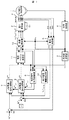
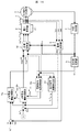
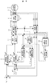
図1は、本発明の一実施例である「永久磁石同機電動機のベクトル制御装置」の構成例を示す。
<First embodiment>
FIG. 1 shows an example of the configuration of a “vector control device for a permanent magnet motor” that is an embodiment of the present invention.
1は永久磁石同期電動機、
2は3相交流の電圧指令値Vu*,Vv*,Vw*に比例した電圧を出力する電力変換器、
21は直流電源、
3は3相交流電流Iu,Iv,Iwを検出できる電流検出器、
4は永久磁石同期電動機1の位置θを検出できるレゾルバやエンコーダを用いた位置検出器、
5は位置検出値θcから周波数演算値ω1を演算する周波数演算部、
6は3相交流電流Iu,Iv,Iwの検出値Iuc,Ivc,Iwcと、
永久磁石同期電動機1の位置検出値θcからd軸およびq軸の電流検出値Idc,Iqcを出力する座標変換部、
7は第1のq軸電流指令値Iq*とq軸電流検出値Iqcの偏差に応じて、第2のq軸電流指令値Iq**を演算し、出力電圧制限フラグV1 * lmt_flgを用いて、
内部で設定した制限値Iq** lmt0あるいは演算により求めた制限値Iq** lmtを選択し、Iq**を制限して出力するq軸電流指令演算部、
8は第1のd軸電流指令値Id*とd軸電流検出値Idcの偏差に応じて、第2のd軸電流指令値Id**を演算し、出力電圧制限フラグV1 * lmt_flgを用いて、
内部で設定した制限値Id** lmt0あるいは演算により求めた制限値Id** lmtを選択し、Id**を制限して出力するd軸電流指令演算部、
7,8は積分演算あるいは比例演算+積分演算で構成されるものである。
1 is a permanent magnet synchronous motor,
2 is a power converter that outputs a voltage proportional to the voltage command values Vu * , Vv * , and Vw * of a three-phase alternating current;
21 is a DC power supply,
3 is a current detector that can detect three-phase alternating currents Iu, Iv, Iw,
4 is a position detector using a resolver or encoder capable of detecting the position θ of the permanent magnet
5 is a frequency calculation unit for calculating a frequency calculation value ω 1 from the position detection value θc;
6 is the detected values Iuc, Ivc, Iwc of the three-phase alternating currents Iu, Iv, Iw,
A coordinate converter that outputs current detection values Idc and Iqc of the d-axis and q-axis from the position detection value θc of the permanent magnet
7 calculates the second q-axis current command value Iq ** according to the deviation between the first q-axis current command value Iq * and the q-axis current detection value Iqc, and uses the output voltage limit flag V 1 * lmt_flg . And
Select limit value Iq ** lmt determined by restriction value Iq ** lmt0 or calculation set internally, q-axis current command calculating unit which outputs the limit Iq **,
8 calculates the second d-axis current command value Id ** according to the deviation between the first d-axis current command value Id * and the detected d-axis current value Idc, and uses the output voltage limit flag V 1 * lmt_flg . And
Select limit value Id ** lmt determined by restriction value Id ** lmt0 or calculation set internally, d-axis current instruction operation section which outputs the limit Id **,
7 and 8 are constituted by integral calculation or proportional calculation + integral calculation.
9はd軸およびq軸の電圧指令値Vdc*,Vqc*と周波数演算値ω1および永久磁石同期電動機1の定数に基づいて、第2の電流指令値の制限値Id** lmt,Iq** lmtを出力する電流指令制限演算部、
10はd軸およびq軸の電圧指令値Vdc*,Vdc*から電力変換器の出力電圧値V1 *を演算し、
出力電圧指令値V1 *が電圧制限値V1 * maxより小さい場合は、出力電圧制限フラグV1 * lmt_flgを「0」、
V1 *がV1 * maxに到達した場合は、出力電圧制限フラグV1 * lmt_flgを「1」、
に設定する出力電圧制限検出部である。
9 d-axis and q-voltage command value of the axis Vdc *, Vqc * and on the basis of the constant frequency operation value omega 1 and the permanent magnet
10 calculates the output voltage value V 1 * of the power converter from the d-axis and q-axis voltage command values Vdc * and Vdc * ,
When the output voltage command value V 1 * is smaller than the voltage limit value V 1 * max , set the output voltage limit flag V 1 * lmt_flg to “0”,
When V 1 * reaches V 1 * max , the output voltage limit flag V 1 * lmt_flg is set to “1”,
The output voltage limit detection unit is set to
ここで、電圧制限値V1 * max:電力変換器に供給する直流電圧値Edから決まる制限値であり、電力変換器を正弦波変調した場合は、V1 * maxは(数1)となる。 Here, the voltage limit value V 1 * max is a limit value determined from the direct-current voltage value Ed supplied to the power converter. When the power converter is sinusoidally modulated, V 1 * max is (Expression 1). .

また、3相交流の電圧指令値Vu*,Vv*,Vw*に、線間電圧では相殺される同相の信号(例えば、3倍調波)を重畳させた場合は、V1 * maxは(数2)となる。 In addition, when an in-phase signal (for example, triple harmonic) that is canceled by the line voltage is superimposed on the voltage command values Vu * , Vv * , and Vw * of the three-phase alternating current, V 1 * max is ( Equation 2).
11は永久磁石同期電動機1の電気定数と第2のd軸電流指令値Id**,第2のq軸電流指令値Iq**および周波数指令値ω1に基づいて、d軸電圧指令値Vdc*,q軸電圧指令値Vqc*を演算する電圧ベクトル演算部、
12はd軸およびq軸の電圧指令値Vdc*,Vdc*と位置検出値θcから3相交流の電圧指令値Vu*,Vv*,Vw*を出力する座標変換部である。
11 is a d-axis voltage command value Vdc based on the electric constant of the permanent magnet
A
次に、本発明の特徴である電流指令制限演算部9を用いたベクトル制御方式の電圧制御と位相制御の基本動作について説明する。
Next, basic operations of voltage control and phase control of the vector control method using the current command
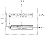
まず、電圧制御については、図2を用いて、電流指令制限演算部9の構成を説明する。
First, regarding the voltage control, the configuration of the current command
91は、d軸およびq軸の電圧指令値Vdc*,Vqc*と周波数演算値ω1および永久磁石同期電動機1の定数(R*,Ld*,Lq*,Ke*)を用いて、(数3)に従い、第2のd軸電流指令値Id**の制限値Id** lmtを演算する。
91 is expressed by using the d-axis and q-axis voltage command values Vdc * , Vqc * , the frequency calculation value ω 1, and the constants (R * , Ld * , Lq * , Ke * ) of the permanent magnet
92では、d軸およびq軸の電圧指令値Vdc*,Vqc*と周波数演算値ω1および永久磁石同期電動機1の定数を用いて、(数4)に従い、第2のq軸電流指令値Iq**の制限値Iq** lmtを演算する。
92, the second q-axis current command value Iq according to (Equation 4) using the d-axis and q-axis voltage command values Vdc * and Vqc * , the frequency calculation value ω 1 and the constant of the permanent magnet
ここで、R*は、抵抗の設定値、Ld*はd軸インダクタンスの設定値、Lq*はq軸インダクタンスの設定値、Ke*は、誘起電圧定数の設定値を表す。 Here, R * is a resistance setting value, Ld * is a d-axis inductance setting value, Lq * is a q-axis inductance setting value, and Ke * is an induced voltage constant setting value.
また、図1中の出力電圧制限検出部10においては、(数5)により、d軸およびq軸の電圧指令値Vdc*,Vqc*を用いて出力電圧値V1 *を演算する。 1 calculates the output voltage value V 1 * using the d-axis and q-axis voltage command values Vdc * and Vqc * by (Equation 5).
![]()
![]()
さらに、出力電圧指令値V1 *と電圧制限値V1 * maxを用いて、(数6)に従い、出力電圧制限フラグV1 * lmt_flgを作成する。 Further, using the output voltage command value V 1 * and the voltage limit value V 1 * max , an output voltage limit flag V 1 * lmt_flg is created according to ( Equation 6).
電力変換器2の出力電圧値V1が制限された場合は、これらの第2のd軸電流指令値の制限値Id** lmt,第2のq軸電流指令値の制限値Iq** lmtと出力電圧制限フラグV1 * lmt_flgを用いて、q軸電流指令演算部7とd軸電流指令演算部8の出力値を制限する動作を行う。
If the output voltage value V 1 of the
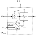
図3には、q軸電流指令演算部7の構成を示す。ここでは、構成が簡単な積分演算を例としている。
FIG. 3 shows the configuration of the q-axis current
第1のq軸電流指令値Iq*とq軸電流検出値Iqcの偏差であるΔIqは、積分ゲインがKである積分演算部71に入力され、第2のq軸電流指令値Iq**を演算する。
ΔIq, which is a deviation between the first q-axis current command value Iq * and the q-axis current detection value Iqc, is input to the
制限値の選択部72において、出力電圧制限フラグV1 * lmt_flgが「0」のとき、72内部で設定された制限値Iq** lmt0が選択され、V1 * lmt_flgが「1」のときは、電流指令制限演算部9の出力である第2のq軸電流指令値の制限値Iq** lmtが選択され、制限値Iq** lmt_setとして出力する。
In the limit
制限部73には、第2のq軸電流指令値Iq**と制限値Iq** lmt_setが入力されるが、Iq**とIq** lmt_setが同符号(どちらも正あるいは負の極性)の場合は、Iq**の絶対値|Iq**|とIq** lmt_setの絶対値|Iq** lmt_set|を比較し、(数7)に従い、Iq**を出力する。 Although the second q-axis current command value Iq ** and the limit value Iq ** lmt_set are input to the limiter 73 , Iq ** and Iq ** lmt_set have the same sign (both positive or negative polarity) for the absolute value of Iq ** | Iq ** | and Iq ** absolute value of lmt_set | Iq ** lmt_set | compare, according equation (7), and outputs the Iq **.
また、Iq**とIq** lmt_setが異符号(どちらかが正、一方が負の極性)の場合は、(数8)に従い、Iq** lmt_setをIq**として出力する。 Further, Iq ** and Iq ** lmt_set is different signs (either positive, one negative polarity) in the case of, in accordance with equation (8), and outputs the Iq ** lmt_set as Iq **.
![]()
![]()
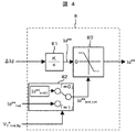
同様に、図4に示すd軸電流指令演算部8でも、第1のd軸電流指令値Id*とd軸電流検出値Idcの偏差であるΔIdは、積分ゲインがKである積分演算部81に入力され、第2のd軸電流指令値Id**を演算する。
Similarly, in the d-axis current
制限値の選択部82において、出力電圧制限フラグV1 * lmt_flgが「0」のとき、82内部で設定された制限値Id** lmt0が、V1 * lmt_flgが「1」のときは、電流指令制限演算部9の出力である第2のd軸電流指令値の制限値Id** lmtが選択され、制限値Id** lmt_setとして出力する。
In
制限部83には、第2のd軸電流指令値Id**と制限値Id** lmt_setが入力されるが、Id**とId** lmt_setが同符号(どちらも正あるいは負の極性)の場合は、Id**の絶対値|Id**|とId** lmt_setの絶対値|Id** lmt_set|を比較し、(数9)に従い、Id**を出力する。
The
また、Id**とId** lmt_setが異符号(どちらかが正、一方が負の極性)の場合は、(数10)に従い、Id** lmt_setをId**として出力する。 Also, Id ** and Id ** lmt_set is different signs (either positive, one negative polarity) in the case of, in accordance with equation (10), and outputs the Id ** lmt_set as Id **.
![]()
![]()
また、電圧ベクトル演算部11では、(数11)で示すように、第2のd軸およびq軸の電流指令値Id**,Iq**と周波数演算値ω1および永久磁石同期電動機1の定数を用いて、d軸およびq軸の電圧指令値Vdc*,Vqc*を演算し、変換器の出力電圧値V1を制御する。
Further, in the voltage
一方、位相制御では、レゾルバやエンコーダなどの位置検出器4において、永久磁石同期電動機1の位置θを検出し、位置検出値θcを得る。
On the other hand, in the phase control, the
周波数演算部5では、この位置検出値θcを用いて、(数12)により周波演算令値ω1を求める。
The
以上が、電圧制御と位相制御の基本動作である。 The above is the basic operation of voltage control and phase control.
次に、本発明のもたらす作用効果について、本実施例により説明する。 Next, the effect which this invention brings about is demonstrated by a present Example.
図1の制御装置において、第2のd軸およびq軸の電流指令値Id**,Iq**の制限に、電流指令制限演算部9の第2のd軸電流指令値の制限値Id** lmt,第2のq軸電流指令値の制限値Iq** lmtを用いない場合の制御特性について説明する。
In the control device of FIG. 1, the second d-axis current command value limit value Id * of the current command
q軸電流指令演算部7,d軸電流指令演算部8では、出力電圧値が制限されていない場合(V1 * lmt_flg=0)には、72,82内部で設定された制限値Iq** lmt0,Id** lmt0により、積分演算部71と81の出力は制限される。
In the q-axis current
しかし、出力電圧値が制限された場合(V1 * lmt_flg=1)には、積分演算部71と81の更新を中止し、制限から回復した(V1 * lmt_flg=0)ときに、積分演算部71と81の更新を再開する。
However, when the output voltage value is limited (V 1 * lmt_flg = 1), the updating of the
一方、従来方式である特開平9−47069号公報に記載の方法と等価にするため、第1の電流指令値を第2の電流指令値に加算する「フィードフォワード補償」を行うと、第3の電流指令値Id***,Iq***は、(数13)のようになる。 On the other hand, in order to make it equivalent to the method described in Japanese Patent Laid-Open No. 9-47069 which is a conventional method, when “feed forward compensation” is performed in which the first current command value is added to the second current command value, The current command values Id *** and Iq *** are expressed as (Equation 13).
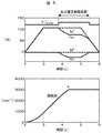
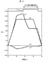
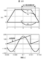
この従来の制御方式を用いて、台形波状の第1のq軸電流指令値Iq*を与え、駆動した制御特性を図5,図6に示す。 Using this conventional control method, a trapezoidal first q-axis current command value Iq * is given, and the drive control characteristics are shown in FIGS.
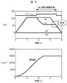
図5は、永久磁石同期電動機1の定数と電圧ベクトル演算部11に設定する定数が一致している場合の制御特性である。a点から加速してb点で最高回転数に到達していることがわかる。ここで、電力変換器の出力電圧値V1が制限される区間(V1 * lmt_flg=1)では、d軸およびq軸の電流検出値Idc,Iqcが、第1のd軸電流指令値Id*,第1のq軸電流指令値Iq*に追従していないが、安定に制御運転できていることがわかる。
FIG. 5 shows control characteristics when the constants of the permanent
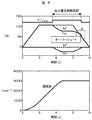
一方、図6は、永久磁石同期電動機1の定数と電圧ベクトル演算部11に設定する定数が一致していない場合(Lq*=0.8×Lq,Ld*=0.8×Ld)の制御特性である。
On the other hand, FIG. 6 shows the control when the constant of the permanent
この場合、電圧ベクトル演算部11に設定の誤差が在ると、図6のA領域で、q軸の電流検出値Iqcに「オーバーシュート」が発生しており、モータトルクには、これに起因した「ショック」が発生する。
In this case, if there is a setting error in the voltage
図7には、(数13)に用いた第2のd軸及びq軸電流指令値Id**,Iq**の波形を示す。 FIG. 7 shows waveforms of the second d-axis and q-axis current command values Id ** and Iq ** used in (Equation 13).
出力電圧値が制限されている区間(V1 * lmt_flg=1)では、積分演算部の出力値であるId**,Iq**が、c0点より保持されており、制限から回復したc1点において、Id**,Iq**が急激に変化している様子がわかる。 In the section where the output voltage value is limited (V 1 * lmt_flg = 1), the output values Id ** and Iq ** of the integration calculation unit are held from the point c 0 and c recovered from the limit. It can be seen that at one point, Id ** and Iq ** change rapidly.
これが、q軸電流検出値Iqcの「オーバーシュートの原因」となっている。 This is the “cause of overshoot” of the q-axis current detection value Iqc.
つまり、永久磁石同期電動機1の回転数や与えるトルク指令値の条件により、出力電圧制限区間に入る直前のc0点と制限から回復したc1点では、最適なIq**の値が異なることが分かる。
In other words, depending on the rotational speed of the permanent
そこで、出力電圧値V1が制限された場合は、積分演算部の値を保持する方式ではなく、新しく電流指令制限演算部9を設け、回転数や与えるトルク指令値の条件により、連続的に、積分演算部の出力を制限する。
Therefore, when the output voltage value V 1 is limited, instead of a method of holding the value of the integral calculation unit, a new current command
本発明の特徴である電流指令制限演算部9では、d軸およびq軸の電圧指令値Vdc*,Vqc*と周波数演算値ω1および永久磁石同期電動機1の定数を用いて、回転周波数や電流指令値の状態に応じて、第2のd軸及びq軸電流指令値Id**,Iq**の制限値Id** lmt,Iq** lmtを演算する。
The current command
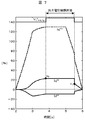
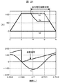
図8には、本発明での出力電圧飽和制御(図7,図8使用)を行った場合の特性(Lq*=0.8×Lq,Ld*=0.8×Ld)を示す。 FIG. 8 shows the characteristics (Lq * = 0.8 × Lq, Ld * = 0.8 × Ld) when the output voltage saturation control (using FIGS. 7 and 8) according to the present invention is performed.
永久磁石同期電動機1の定数と電圧ベクトル演算部11に設定する定数が一致していない場合でも、従来(図6)のようなA領域におけるIqcのオーバーシュートは無くなり、制限から回復する際にも安定な制御特性となることが分かる。
Even when the constants of the permanent
図9には、q軸電流指令演算部7,d軸電流指令演算部8における積分演算部の出力値である第2のd軸及びq軸電流指令値Id**,Iq**の波形を示す。
FIG. 9 shows waveforms of the second d-axis and q-axis current command values Id ** and Iq ** , which are output values of the integral calculation unit in the q-axis current
出力電圧値V1が制限される区間(V1 * lmt_flg=1)においても、Id**,Iq**は連続的に制限されている様子が分かる。 Even in a section where the output voltage value V 1 is limited (V 1 * lmt_flg = 1) , Id **, Iq ** is it can be seen being continuously limited.
本実施例では、q軸電流指令演算部7,d軸電流指令演算部8の演算構成を積分演算としたが、比例演算+積分演算にした場合でも、本実施例と同様の効果を得ることができる。
In this embodiment, the calculation configuration of the q-axis current
<第2の実施例>
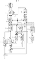
図10は、本発明の第2の実施例を示す。
<Second Embodiment>
FIG. 10 shows a second embodiment of the present invention.
本実施例は、d軸およびq軸の電流制御演算部を設けたベクトル制御装置に、本発明を適用した一例である。図において、構成要素の1〜6,10,12,21は、図1のものと同一物である。
The present embodiment is an example in which the present invention is applied to a vector control device provided with d-axis and q-axis current control arithmetic units. In the figure,
7aは第1のq軸電流指令値Iq*とq軸電流検出値Iqcの偏差に応じて、第2のq軸電圧指令値ΔVqを演算し、出力電圧制限フラグV1 * lmt_flgから、内部で設定した制限値ΔVqlmt0、あるいは演算により求めた第2のq軸電圧指令値の制限値ΔVqlmtを選択し、ΔVqを制限して出力するq軸電流制御演算部、8aは第1のd軸電流指令値Id*とd軸電流検出値Idcの偏差に応じて、第2のd軸電圧指令値ΔVdを演算し、出力電圧制限フラグV1 * lmt_flgから、内部で設定した制限値ΔVdlmt0、あるいは演算により求めた第2のd軸電圧指令値の制限値ΔVdlmtを選択し、ΔVdを制限して出力するd軸電流制御演算部を表す。 7a calculates a second q-axis voltage command value ΔVq in accordance with the deviation between the first q-axis current command value Iq * and the q-axis current detection value Iqc, and from the output voltage limit flag V 1 * lmt_flg , the set limit value ΔVq lmt0, or select the limit value? Vq lmt of the second q-axis voltage command value calculated by the calculation, q-axis current control calculation section for outputting the limit? Vq, 8a the first d-axis depending on the deviation between the current command value Id * and the d-axis current detection value Idc, the second d-axis voltage command value .DELTA.Vd calculated from the output voltage limiting flag V 1 * lmt_flg, limit .DELTA.Vd Lmt0 set internally, Alternatively, a d-axis current control calculation unit that selects and outputs a limit value ΔVd lmt of the second d-axis voltage command value obtained by calculation and limits ΔVd is represented.
また、9aはd軸およびq軸の電圧指令値Vdc**,Vqc**と周波数演算値ω1と第1のd軸およびq軸の電流指令値Id*,Iq*および永久磁石同期電動機1の定数に基づいて、第2のd軸電圧指令値の制限値ΔVdlmt,第2のd軸電圧指令値の制限値ΔVdlmtを出力する電圧指令制限演算部、11aは永久磁石同期電動機1の定数と第1のd軸及びq軸電流指令値Id*,Iq*と周波数指令値ω1および電流制御の出力値ΔVd,ΔVqに基づいて、d軸及びq軸電圧指令値Vdc**,Vqc**を演算する電圧ベクトル演算部を表す。
Further, 9a voltage command value Vdc ** of the d-axis and q-axis, Vqc ** and frequency calculation value omega 1 and the first d-axis and the current command value of q-axis Id *, Iq * and the permanent magnet synchronous motor 1 Is a voltage command limit calculation unit that outputs a limit value ΔVd lmt of the second d-axis voltage command value and a limit value ΔVd lmt of the second d-axis voltage command value, and 11 a is a permanent
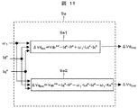
次に、図11を用いて、電圧指令制限演算部9aの構成を説明する。
Next, the configuration of the voltage command
9a1は、d軸の電圧指令値Vdc**と周波数演算値ω1と第1のd軸およびq軸の電流指令値Id*,Iq*および永久磁石同期電動機1の定数(R*,Ld*,Lq*,Ke*)を用いて、(数14)に従い、第2のd軸電圧指令値ΔVdの制限値ΔVdlmtを演算する。
9a1 is a d-axis voltage command value Vdc ** , a frequency calculation value ω 1 , first d-axis and q-axis current command values Id * , Iq *, and constants (R * , Ld *) of the permanent
![]()
![]()
9a2では、q軸の電圧指令値Vqc**と周波数演算値ω1と第1のd軸およびq軸の電流指令値Id*,Iq*および永久磁石同期電動機1の定数(R*,Ld*,Lq*,Ke*)を用いて、(数15)に従い第2のq軸電圧指令値ΔVqの制限値ΔVqlmtを演算する。
9 a 2, the q-axis voltage command value Vqc ** , the frequency calculation value ω 1 , the first d-axis and q-axis current command values Id * , Iq *, and the constants (R * , Ld *) of the permanent
![]()
![]()
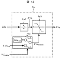
図12には、q軸電流制御演算部7aの構成を示す。ここでは、構成が簡単な積分演算を例としている。
FIG. 12 shows the configuration of the q-axis current
第1のq軸電流指令値Iq*とq軸電流検出値Iqcの偏差であるΔIqは、積分ゲインがKである積分演算部7a1に入力され、第2のq軸電圧指令値ΔVqを演算する。制限値の選択部7a2において、出力電圧制限フラグV1 * lmt_flgが「0」のとき、7a2内部で設定された制限値ΔVqlmt0が、V1 * lmt_flgが「1」のときは、電圧指令制限演算部9aの出力である第2のq軸電圧指令値の制限値ΔVqlmtが選択され、制限値ΔVqlmt_setとして出力する。
ΔIq, which is a deviation between the first q-axis current command value Iq * and the q-axis current detection value Iqc, is input to the integral calculation unit 7a1 having an integral gain K, and calculates the second q-axis voltage command value ΔVq. . In selecting unit 7a2 limits, when the output voltage limiting flag V 1 * lmt_flg is "0", the limitation value? Vq Lmt0 internally set 7a2, when V 1 * lmt_flg is "1", the voltage command limit The limit value ΔVq lmt of the second q-axis voltage command value, which is the output of the
制限部7a3には、第2のq軸電圧指令値ΔVqと制限値ΔVqlmt_setが入力されるが、ΔVqとΔVqlmt_setが同符号(どちらも正あるいは負の極性)の場合は、ΔVqの絶対値|ΔVq|とΔVqlmt_setの絶対値|ΔVqlmt_set|を比較し、(数16)に従い、ΔVqを出力する。 The limit unit 7a3 receives the second q-axis voltage command value ΔVq and the limit value ΔVq lmt_set . If ΔVq and ΔVq lmt_set have the same sign (both positive or negative polarity), the absolute value of ΔVq |? Vq | and? Vq absolute value of lmt_set | ΔVq lmt_set | compare, according equation (16), and outputs the? Vq.
また、ΔVqとΔVqlmt_setが異符号(どちらかが正、一方が負の極性)の場合は、
(数17)に従い、ΔVqlmt_setをΔVqとして出力する。
In addition, when ΔVq and ΔVq lmt_set have different signs (one is positive and one is negative)
According to ( Equation 17), ΔVq lmt_set is output as ΔVq.
![]()
![]()
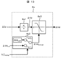
図13には、d軸電流制御演算部8aの構成を示す。ここでも、構成が簡単な積分演算を例にしている。
FIG. 13 shows the configuration of the d-axis current
第1のd軸電流指令値Id*とd軸電流検出値Idcの偏差であるΔIdは、積分ゲインがKである積分演算部8a1に入力され、第2のd軸電圧指令値ΔVdを演算する。制限値の選択部8a2において、出力電圧制限フラグV1 * lmt_flgが「0」のとき、8a2内部で設定された制限値ΔVdlmt0が選択され、出力電圧制限フラグV1 * lmt_flgが「1」のときは、電圧指令制限演算部9aの出力である第2のd軸電圧指令値の制限値ΔVdlmtが選択され、制限値ΔVdlmt_setとして出力する。
ΔId, which is the deviation between the first d-axis current command value Id * and the detected d-axis current value Idc, is input to the integral calculation unit 8a1 whose integral gain is K, and calculates the second d-axis voltage command value ΔVd. . In the limit value selection unit 8a2, when the output voltage limit flag V 1 * lmt_flg is “0”, the limit value ΔVd lmt0 set inside 8a2 is selected, and the output voltage limit flag V 1 * lmt_flg is “1”. At this time, the limit value ΔVd lmt of the second d-axis voltage command value, which is the output of the voltage command
制限部8a3には、第2のd軸電圧指令値ΔVdと制限値ΔVdlmt_setが入力されるが、ΔVdとΔVdlmt_settが同符号(どちらも正あるいは負の極性)の場合は、ΔVdの絶対値|ΔVd|とΔVdlmt_setの絶対値|ΔVdlmt_set|を比較し、(数18)に従い、ΔVdを出力する。 The limit unit 8a3 receives the second d-axis voltage command value ΔVd and the limit value ΔVd lmt_set . If ΔVd and ΔVd lmt_sett have the same sign (both positive or negative polarity), the absolute value of ΔVd | .DELTA.Vd | and .DELTA.Vd absolute value of lmt_set | ΔVd lmt_set | compare, according equation (18), and outputs the .DELTA.Vd.
また、ΔVdとΔVdlmt_setが異符号(どちらかが正、一方が負の極性)の場合は、
(数19)に従い、ΔVqlmt_setをΔVqとして出力する。
If ΔVd and ΔVd lmt_set have different signs (one is positive and one is negative)
According to ( Equation 19), ΔVq lmt_set is output as ΔVq.
![]()
![]()
また、電圧ベクトル演算部11aでは、(数20)で示すように、第1のd軸およびq軸の電流指令値Id*,Iq*と周波数演算値ω1および永久磁石同期電動機1の定数を用いて、第1のd軸およびq軸の電圧指令値Vdc*,Vqc*を演算し、第2のd軸およびq軸の電圧指令値ΔVd,ΔVqを加算して、変換器の出力電圧値V1を制御する。
Further, in the voltage
このような実施例でも、第1の実施例と同様な効果を得ることができる。 Even in this embodiment, the same effect as that of the first embodiment can be obtained.
また本実施例でも、q軸電流制御演算部7a,d軸電流制御演算部8aの演算構成を積分演算にしたが、比例+積分演算にしても、本実施例と同様の効果を得ることができる。
Also in this embodiment, the calculation configuration of the q-axis current
<第3の実施例>
図14は、本発明の第3の実施例を示す。
<Third embodiment>
FIG. 14 shows a third embodiment of the present invention.
本実施例は、d軸およびq軸の電流制御演算部を設けたベクトル制御装置に、本発明を適用した一例である(フィードバック制御のみ)。図において、構成要素の1〜6,10,12,21は、図1のものと同一物である。
The present embodiment is an example in which the present invention is applied to a vector control device provided with d-axis and q-axis current control arithmetic units (feedback control only). In the figure,
7bは第1のq軸電流指令値Iq*とq軸電流検出値Iqcの偏差に応じて、q軸電圧指令値Vqc***を演算し、出力電圧制限フラグV1 * lmt_flgから、内部で設定した制限値Vqc*** lmt0、あるいは演算により求めたq軸電圧指令値の制限値Vqc*** lmtを選択し、Vqc***を制限して出力するq軸電流制御演算部、8bは第1のd軸電流指令値Id*とd軸電流検出値Idcの偏差に応じて、d軸電圧指令値Vdc***を演算し、出力電圧制限フラグV1 * lmt_flgから、内部で設定した制限値Vdc*** lmt0、あるいは演算により求めたd軸電圧指令値の制限値Vdc*** lmtを選択し、Vdc***を制限して出力するd軸電流制御演算部を表す。
7b calculates a q-axis voltage command value Vqc *** in accordance with the deviation between the first q-axis current command value Iq * and the q-axis current detection value Iqc, and from the output voltage limit flag V 1 * lmt_flg , the set limit value Vqc *** lmt0, or select the limit value Vqc *** lmt of q-axis voltage command value calculated by the calculation, q-axis current control calculation section for outputting the
また、9bはd軸およびq軸の電圧指令値Vdc***,Vqc***と周波数演算値ω1と第1のd軸およびq軸の電流指令値Id*,Iq*および永久磁石同期電動機1の定数に基づいて、d軸及びq軸電圧指令値の制限値Vdc*** lmt,Vqc*** lmtを出力する電圧指令制限演算部を表す。
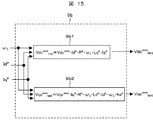
図15を用いて、電圧指令制限演算部9bの構成を説明する。
The configuration of the voltage command
9b1は、d軸の電圧指令値Vdc***と周波数演算値ω1と第1のd軸およびq軸の電流指令値Id*,Iq*および永久磁石同期電動機1の定数(R*,Ld*,Lq*,Ke*)を用いて、(数21)に従い、d軸電圧指令値Vdc***の制限値Vdc*** lmtを演算する。
9b1 is the voltage command value of d-axis Vdc *** and frequency calculation value omega 1 and a current command value of the first d-axis and q-axis Id *, Iq * and the permanent
![]()
![]()
9b2では、q軸の電圧指令値Vqc***と周波数演算値ω1と第1のd軸およびq軸の電流指令値Id*,Iq*および永久磁石同期電動機1の定数(R*,Ld*,Lq*,Ke*)を用いて、(数22)に従い、q軸電圧指令値Vqc***の制限値Vqc*** lmtを演算する。
In 9b2, voltage command value of the q-axis Vqc *** and the current command value of the frequency calculation value omega 1 and the first d-axis and q-axis Id *, Iq * and the permanent
![]()
![]()
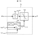
図16には、q軸電流制御演算部7bの構成を示す。ここでは、構成が簡単な積分演算を例としている。
FIG. 16 shows the configuration of the q-axis current
第1のq軸電流指令値Iq*とq軸電流検出値Iqcの偏差であるΔIqは、積分ゲインがKである積分演算部7b1に入力され、q軸電圧指令値Vqc***を演算する。 ΔIq, which is a deviation between the first q-axis current command value Iq * and the q-axis current detection value Iqc, is input to the integral calculation unit 7b1 whose integral gain is K, and calculates the q-axis voltage command value Vqc *** . .
制限値の選択部7b2において、出力電圧制限フラグV1 * lmt_flgが「0」のとき、7b2内部で設定された制限値Vqc*** lmt0が、出力電圧制限フラグV1 * lmt_flgが「1」のときは、電圧指令制限演算部9bの出力であるq軸電圧指令値の制限値Vqc*** lmtが選択され、制限値Vqc*** _setとして出力する。
In the limit value selection unit 7b2 , when the output voltage limit flag V 1 * lmt_flg is “0”, the limit value Vqc *** lmt0 set in 7b2 is set, and the output voltage limit flag V 1 * lmt_flg is “1”. In this case, the limit value Vqc *** lmt of the q-axis voltage command value, which is the output of the voltage command
制限部7b3には、q軸電圧指令値Vqc***と制限値Vqc*** lmt_setが入力されるが、Vqc***とVqc*** lmt_settが同符号(どちらも正あるいは負の極性)の場合は、Vqc***の絶対値|Vqc***|とVqc*** lmt_setの絶対値|Vqc*** lmt_set|を比較し、(数23)に従い、Vqc***を出力する。 The q-axis voltage command value Vqc *** and the limit value Vqc *** lmt_set are input to the limiter 7b3, but Vqc *** and Vqc *** lmt_sett have the same sign (both positive or negative polarity) case of) the absolute value of Vqc *** | Vqc *** | and Vqc *** absolute value of lmt_set | Vqc *** lmt_set | compare, according equation (23), outputs Vqc *** To do.
また、Vqc***とVqc*** lmt_setが異符号(どちらかが正、一方が負の極性)の場合は、(数24)に従い、Vqc*** lmt_setをVqc***として出力する。 Further, Vqc *** and Vqc *** lmt_set is different signs (either positive, one negative polarity) in the case of, in accordance with equation (24), and outputs the Vqc *** lmt_set as Vqc *** .
![]()
![]()
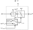
図17には、d軸電流制御演算部8bの構成を示す。
FIG. 17 shows the configuration of the d-axis current
第1のd軸電流指令値Id*とd軸電流検出値Idcの偏差であるΔIdは、積分ゲインがKである積分演算部8b1に入力され、d軸電圧指令値Vdc***を演算する。 ΔId, which is a deviation between the first d-axis current command value Id * and the detected d-axis current value Idc, is input to the integral calculation unit 8b1 whose integral gain is K, and calculates the d-axis voltage command value Vdc *** . .
制限値の選択部8b2において、出力電圧制限フラグV1 * lmt_flgが「0」のとき、78b2内部で設定された制限値Vdc*** lmt0が、出力電圧制限フラグV1 * lmt_flgが「1」のときは、電圧指令制限演算部9bの出力であるd軸電圧指令値の制限値Vdc*** lmtが選択され、制限値Vdc*** lmt_setとして出力する。
In the limit value selection unit 8b2, when the output voltage limit flag V 1 * lmt_flg is “0”, the limit value Vdc *** lmt0 set in 78b2 is set, and the output voltage limit flag V 1 * lmt_flg is “1”. In this case, the limit value Vdc *** lmt of the d-axis voltage command value, which is the output of the voltage command
制限部8b3には、d軸電圧指令値Vdc***と制限値Vdc*** lmt_setが入力されるが、Vdc***とVdc*** lmt_setが同符号(どちらも正あるいは負の極性)の場合は、Vdc***の絶対値|Vdc***|とVdc*** lmt_setの絶対値|Vdc*** lmt_set|を比較し、(数25)に従い、Vdc***を出力する。 The d-axis voltage command value Vdc *** and the limit value Vdc *** lmt_set are input to the limiter 8b3, but Vdc *** and Vdc *** lmt_set have the same sign (both positive or negative polarity) case of) the absolute value of Vdc *** | Vdc *** | and Vdc *** absolute value of lmt_set | Vdc *** lmt_set | compare, according equation (25), outputs a Vdc *** To do.
また、Vdc***とVdc*** lmt_setが異符号(どちらかが正、一方が負の極性)の場合は、(数26)に従い、Vdc*** lmt_setをVdc***として出力する。 Further, Vdc *** and Vdc *** lmt_set is different signs (either positive, one negative polarity) in the case of, in accordance with equation (26), and outputs a Vdc *** lmt_set as Vdc *** .
![]()
![]()
このような実施例でも、第1の実施例と同様な効果を得ることができる。 Even in this embodiment, the same effect as that of the first embodiment can be obtained.
また本実施例では、q軸電流制御演算部7b,d軸電流制御演算部8bの演算構成を積分演算にしたが、比例+積分演算にしても、本実施例と同様の効果を得ることができる。
In the present embodiment, the calculation configuration of the q-axis current
<第4の実施例>
図18は、本発明の第4の実施例を示す。
<Fourth embodiment>
FIG. 18 shows a fourth embodiment of the present invention.
本実施例は、レゾルバやエンコーダなどの位置検出器を省略した制御装置に適用したものである。図において、構成要素の1〜3,6〜12,21は、図1のものと同一物である。 This embodiment is applied to a control device in which a position detector such as a resolver or an encoder is omitted. In the figure, components 1-3, 6-12, and 21 are the same as those in FIG.
13はd軸およびq軸の電圧指令値Vdc*,Vqc*とd軸及びq軸電流検出値Idc,Iqcと周波数演算値ω1および永久磁石同期電動機1の定数に基づいて、(数27)に従い、位相指令値θc′とモータ位相値θの偏差である位相誤差Δθc(=θc′−θ)を推定する誤差演算部を表す。 13 is based on the d-axis and q-axis voltage command values Vdc * , Vqc * , the d-axis and q-axis current detection values Idc, Iqc, the frequency calculation value ω 1, and the constant of the permanent magnet synchronous motor 1 (Equation 27) 2 represents an error calculation unit that estimates a phase error Δθc (= θc′−θ) that is a deviation between the phase command value θc ′ and the motor phase value θ.
14は、位相誤差Δθcを「ゼロ」にするように、周波数推定値ω1′を演算する周波数推定部、15は周波数推定値ω1′を積分して、位相指令値θc′を演算する位相演算部を表す。 14 is a frequency estimator for calculating the estimated frequency value ω 1 ′ so that the phase error Δθc is “zero”, and 15 is a phase for calculating the phase command value θc ′ by integrating the estimated frequency value ω 1 ′. Represents an arithmetic unit.
このような、安価な位置センサレス制御方式においても、前記実施例と同様に動作し、同様の効果が得られることは明らかである。 Even in such an inexpensive position sensorless control system, it is obvious that the operation is the same as in the above-described embodiment and the same effect can be obtained.
また本実施例では、q軸電流制御演算部7,d軸電流制御演算部8の演算構成を積分演算にしたが、比例+積分演算にしても、本実施例と同様の効果を得ることができる。
In this embodiment, the calculation configuration of the q-axis current
また、第2,第3の実施例にある電圧ベクトル演算や電流制御演算を用いても、本実施例と同様の効果を得ることができる。 Also, the same effects as in this embodiment can be obtained by using the voltage vector calculation and the current control calculation in the second and third embodiments.
<第5の実施例>
上記の第1〜第4の実施例までは、高価な電流検出器3で検出した3相の交流電流Iu〜Iwを検出する方式であったが、本発明は、安価な電流検出を行う制御装置においても適用することができる。
<Fifth embodiment>
Up to the above first to fourth embodiments, the three-phase AC currents Iu to Iw detected by the expensive
図19に、第5の実施例を示す。図において、構成要素の1,2,6〜15,21は、図18のものと同一物である。
FIG. 19 shows a fifth embodiment. In the figure,
16は電力変換器の入力母線に流れる直流電流IDCから、永久磁石同期電動機1に流れる3相の交流電流Iu,Iv,Iwを推定する電流推定部である。この推定電流値Iu^,Iv^,Iw^を用い、座標変換部6において、d軸及びq軸の電流検出値Idc,Iqcを演算する。
16 is a current estimator that estimates a DC current I DC flowing through the input bus of the power converter, the
このような、安価な電流センサレス制御方式においても、実施例と同様に動作し、同様の効果が得られることは明らかである。 Even in such an inexpensive current sensorless control system, it is obvious that the operation is the same as in the embodiment and the same effect can be obtained.
また本実施例では、q軸電流制御演算部7,d軸電流制御演算部8の演算構成を積分演算にしたが、比例+積分演算にしても、本実施例と同様の効果を得ることができる。
In this embodiment, the calculation configuration of the q-axis current
また、第2,第3の実施例にある電圧ベクトル演算や電流制御演算を用いても、本実施例と同様の効果を得ることができる。 Also, the same effects as in this embodiment can be obtained by using the voltage vector calculation and the current control calculation in the second and third embodiments.
なお、本発明にかかる実施例では、電力変換器の出力電圧値が制限された場合でも、d軸(磁束)軸電流成分の値を指令値通りに追従させることができる。ここで、図20の上側は、従来の制御特性(図6相当)であり、下側は、このときの出力電圧制限区間における「位置検出値θcと3相交流電流のu相電流Iuの関係」を示したものである。従来方式では、Id*=0でも、Idが発生しているため、位置検出値θcのゼロ点とu相電流Iuのゼロ点の位相が一致していない(Id=0の場合は一致する)。 In the embodiment according to the present invention, even when the output voltage value of the power converter is limited, the value of the d-axis (magnetic flux) axis current component can be made to follow the command value. Here, the upper side of FIG. 20 is the conventional control characteristic (corresponding to FIG. 6), and the lower side is “the relationship between the position detection value θc and the u-phase current Iu of the three-phase alternating current in the output voltage limiting section at this time. Is shown. In the conventional method, even if Id * = 0, since Id is generated, the zero point of the position detection value θc and the phase of the zero point of the u-phase current Iu do not match (when Id = 0, they match). .
一方、図21の上側は、本発明の制御特性(図8相当)であり、下側は、このときの出力電圧制限区間における「位置検出値θcと3相交流電流のu相電流Iuの関係」を示したものである。 On the other hand, the upper side of FIG. 21 is the control characteristic of the present invention (corresponding to FIG. 8), and the lower side is “the relationship between the position detection value θc and the u-phase current Iu of the three-phase alternating current in the output voltage limiting section at this time. Is shown.
本発明では、Id*=0の場合、位置検出値θcのゼロ点とu相電流Iuのゼロ点の位相が一致していることが分かる。このように電力変換器の出力電圧値の制限の有無に拘わらず、永久磁石同期電動機1の位置信号あるいは制御軸の基準信号と、モータ電流の位相との関係を見れば明らかである。
In the present invention, when Id * = 0, it can be seen that the phase of the zero point of the position detection value θc and the phase of the zero point of the u-phase current Iu match. As described above, regardless of whether or not the output voltage value of the power converter is limited, it is clear from the relationship between the position signal of the permanent
1 永久磁石同期電動機
2 電力変換器
3 電流検出器
4 位置検出器
5 周波数演算部
6 座標変換部
7 q軸電流指令演算部
7a,7b q軸電流制御演算部
8 d軸電流指令演算部
8a,8b d軸電流制御演算部
9 電流指令制限演算部
9a,9b 電圧指令制限演算部
10 出力電圧制限検出部
11 電圧ベクトル演算部
12 座標変換部
13 軸誤差演算部
14 周波数推定部
15 位相演算部
16 電流推定部
21 直流電源
Id* 第1のd軸電流指令値
Id** 第2のd軸電流指令値
Id*** 第3のd軸電流指令値
Iq* 第1のq軸電流指令値
Iq** 第2のq軸電流指令値
Iq*** 第3のq軸電流指令値
Idc d軸電流検出値
Iqc d軸電流検出値
Id** lmt 第2のd軸電流指令値の制限値
Iq** lmt 第2のq軸電流指令値の制限値
V1* lmt_flg 出力電圧制限フラグ
ΔVdlmt 第2のd軸電圧指令値の制限値
ΔVqlmt 第2のq軸電圧指令値の制限値
Vdc*** lmt d軸電圧指令値の制限値
Vqc*** lmt q軸電圧指令値の制限値
Vdc*,Vdc**,Vdc*** d軸電圧指令値
Vqc*,Vqc**,Vqc*** q軸電圧指令値
V1* 出力電圧値
θc 位置検出値
ω1 周波数演算値
DESCRIPTION OF SYMBOLS 1 Permanent magnet synchronous motor 2 Power converter 3 Current detector 4 Position detector 5 Frequency calculating part 6 Coordinate converting part 7 q-axis current command calculating part 7a, 7b q-axis current control calculating part 8 d-axis current command calculating part 8a, 8b d-axis current control calculation unit 9 current command limit calculation units 9a and 9b voltage command limit calculation unit 10 output voltage limit detection unit 11 voltage vector calculation unit 12 coordinate conversion unit 13 axis error calculation unit 14 frequency estimation unit 15 phase calculation unit 16 Current estimation unit 21 DC power supply Id * first d-axis current command value Id ** second d-axis current command value Id *** third d-axis current command value Iq * first q-axis current command value Iq ** Second q-axis current command value Iq *** Third q-axis current command value Idc d-axis current detection value Iqc d-axis current detection value Id ** lmt Second d-axis current command value limit value Iq ** lmt second q-axis current command value limit value V1 * lmt_flg output voltage limit flag ΔVd lmt Second d-axis voltage command value limit value ΔVq lmt Second q-axis voltage command value limit value Vdc *** lmt d-axis voltage command value limit value Vqc *** lmt q-axis voltage command value Limit values Vdc * , Vdc ** , Vdc *** d-axis voltage command value Vqc * , Vqc ** , Vqc *** q-axis voltage command value V1 * Output voltage value θc Position detection value ω 1 Frequency calculation value
Claims (20)
電流指令値と電流検出値の偏差により電圧指令値を演算し、前記電力変換器の出力電圧値を制御するベクトル制御装置であって、
前記電力変換器の出力電圧値が制限された場合に、前記出力電圧値と電動機定数と電流指令値および周波数演算値を用いて、前記電圧指令値の制限値を演算することを特徴とする永久磁石同期電動機のベクトル制御装置。 It has a power converter that drives a permanent magnet synchronous motor,
A vector control device that calculates a voltage command value based on a deviation between a current command value and a current detection value, and controls an output voltage value of the power converter,
When the output voltage value of the power converter is limited, the limit value of the voltage command value is calculated using the output voltage value, the motor constant, the current command value, and the frequency calculation value. Vector control device for magnet synchronous motor.
電流指令値又は電流検出値,周波数演算値および電動機定数により演算した第1の電圧指令値と、前記電流指令値と前記電流検出値の偏差により演算した第2の電圧指令値とを加算し、前記電力変換器の出力電圧値を制御するベクトル制御装置であって、
前記電力変換器の前記出力電圧値が制限された場合に、前記出力電圧値と、前記電動機定数,前記電流指令値および前記周波数演算値を用いて、前記第2の電圧指令値の制限値を演算することを特徴とする永久磁石同期電動機のベクトル制御装置。 It has a power converter that drives a permanent magnet synchronous motor,
Adding a first voltage command value calculated from a current command value or current detection value, a frequency calculation value and a motor constant, and a second voltage command value calculated from a deviation between the current command value and the current detection value; A vector control device for controlling an output voltage value of the power converter,
When the output voltage value of the power converter is limited, the limit value of the second voltage command value is calculated using the output voltage value, the motor constant, the current command value, and the frequency calculation value. A vector control device for a permanent magnet synchronous motor, characterized in that the calculation is performed.
第1の電流指令値と電流検出値の偏差により演算した第2の電流指令値と、
周波数演算値と、電動機定数とに応じて前記電力変換器の出力電圧値を制御するベクトル制御装置であって、
前記出力電圧値が制限された場合に、前記出力電圧値と、前記電動機定数と、前記周波数演算値と、を用いて、前記第2の電流指令値の制限値を演算することを特徴とする永久磁石同期電動機のベクトル制御装置。 It has a power converter that drives a permanent magnet synchronous motor,
A second current command value calculated from a deviation between the first current command value and the detected current value;
A vector control device that controls an output voltage value of the power converter according to a frequency calculation value and a motor constant,
When the output voltage value is limited, the limit value of the second current command value is calculated using the output voltage value, the electric motor constant, and the frequency calculation value. Vector controller for permanent magnet synchronous motor.
前記電圧指令値の制限値,前記第2の電圧指令値の制限値或いは前記第2の電流指令値の制限値は、前記電力変換器の出力電圧値と、前記電動機定数である抵抗値と、インダクタンス値と、誘起電圧係数と、周波数演算値と、を用いて演算することを特徴とする永久磁石同期電動機のベクトル制御装置。 The vector control device according to claim 1,
The limit value of the voltage command value, the limit value of the second voltage command value, or the limit value of the second current command value includes an output voltage value of the power converter, a resistance value that is the motor constant, A vector control device for a permanent magnet synchronous motor, wherein the vector control device calculates using an inductance value, an induced voltage coefficient, and a frequency calculation value.
前記電流指令値と前記電流検出値の偏差により演算した電圧指令値、前記第2の電圧指令値或いは前記第2の電流指令値、の出力値の極性と、
各々の出力値に対応する演算された制限値の極性と、が、異なる場合に、演算された前記制限値を出力値とすることを特徴とする永久磁石同期電動機のベクトル制御装置。 The vector control device according to claim 1,
A voltage command value calculated by a deviation between the current command value and the current detection value, a polarity of an output value of the second voltage command value or the second current command value,
A vector control device for a permanent magnet synchronous motor, wherein the calculated limit value is used as an output value when the polarity of the calculated limit value corresponding to each output value is different.
前記電圧指令値の制限値,前記第2の電圧指令値の制限値、或いは前記第2の電流指令値の制限値、を用いて、前記電力変換器の前記出力電圧値を制限することを特徴とする永久磁石同期電動機のベクトル制御装置。 The vector control device according to claim 1,
The output voltage value of the power converter is limited using the limit value of the voltage command value, the limit value of the second voltage command value, or the limit value of the second current command value. A permanent magnet synchronous motor vector control device.
d軸成分あるいはq軸成分の少なくともどちらか一方の制限値を用いて、
前記電力変換器の前記出力電圧値を制限することを特徴とする永久磁石同期電動機のベクトル制御装置。 The vector control device according to claim 6, wherein
Using the limit value of at least one of the d-axis component and the q-axis component,
A vector control device for a permanent magnet synchronous motor, wherein the output voltage value of the power converter is limited.
前記周波数演算値は、d軸およびq軸の電圧指令値と検出したモータ電流或いは再現した電流より、位相指令値とモータの回転位相値との偏差を演算により求め、偏差が零となるように演算して求まることを特徴とする永久磁石モータのベクトル制御装置。 The vector control device according to claim 1,
The frequency calculation value is obtained by calculating the deviation between the phase command value and the rotational phase value of the motor from the d-axis and q-axis voltage command values and the detected motor current or reproduced current so that the deviation becomes zero. A vector controller for a permanent magnet motor, characterized in that it is obtained by calculation.
前記電流検出値は、前記電力変換器の入力直流母線電流検出値から、モータ電流を再現した電流であることを特徴とする永久磁石モータの弱め界磁ベクトル制御装置。 The vector control device according to claim 1,
The field-weakening vector control device for a permanent magnet motor, wherein the current detection value is a current that reproduces a motor current from an input DC bus current detection value of the power converter.
前記電力変換器の出力電圧値が制限された場合に、d軸電流成分の値を指令値通りに追従させることを特徴とする永久磁石同期電動機のベクトル制御装置。 A vector control device that controls an output voltage value of a power converter that drives a permanent magnet synchronous motor,
When the output voltage value of the power converter is limited, the value of the d-axis current component is made to follow the command value.
前記出力電圧値の制限の有無に拘わらず、d軸電流指令値が0の場合に、位置検出値θcのゼロ点とu相電流Iuのゼロ点の位相が一致していることを特徴とする永久磁石同期電動機のベクトル制御装置。 A vector control device that controls an output voltage value of a power converter that drives a permanent magnet synchronous motor,
Regardless of whether the output voltage value is limited or not, when the d-axis current command value is 0, the phase of the zero point of the position detection value θc and the zero point of the u-phase current Iu are the same. Vector controller for permanent magnet synchronous motor.
前記電圧指令値の制限値,前記第2の電圧指令値の制限値或いは前記第2の電流指令値の制限値は、前記電力変換器の出力電圧値と、前記電動機定数である抵抗値と、インダクタンス値と、誘起電圧係数と、周波数演算値と、を用いて演算することを特徴とする永久磁石同期電動機のベクトル制御装置。 The vector control device according to claim 2, wherein
The limit value of the voltage command value, the limit value of the second voltage command value, or the limit value of the second current command value includes an output voltage value of the power converter, a resistance value that is the motor constant, A vector control device for a permanent magnet synchronous motor, wherein the vector control device calculates using an inductance value, an induced voltage coefficient, and a frequency calculation value.
前記電流指令値と前記電流検出値の偏差により演算した電圧指令値、前記第2の電圧指令値或いは前記第2の電流指令値、の出力値の極性と、
各々の出力値に対応する演算された制限値の極性と、が、異なる場合に、演算された前記制限値を出力値とすることを特徴とする永久磁石同期電動機のベクトル制御装置。 The vector control device according to claim 2, wherein
A voltage command value calculated by a deviation between the current command value and the current detection value, a polarity of an output value of the second voltage command value or the second current command value,
A vector control device for a permanent magnet synchronous motor, wherein the calculated limit value is used as an output value when the polarity of the calculated limit value corresponding to each output value is different.
前記電圧指令値の制限値,前記第2の電圧指令値の制限値、或いは前記第2の電流指令値の制限値、を用いて、前記電力変換器の前記出力電圧値を制限することを特徴とする永久磁石同期電動機のベクトル制御装置。 The vector control device according to claim 2, wherein
The output voltage value of the power converter is limited using the limit value of the voltage command value, the limit value of the second voltage command value, or the limit value of the second current command value. A permanent magnet synchronous motor vector control device.
前記周波数演算値は、d軸およびq軸の電圧指令値と検出したモータ電流或いは再現した電流より、位相指令値とモータの回転位相値との偏差を演算により求め、偏差が零となるように演算して求まることを特徴とする永久磁石モータのベクトル制御装置。 The vector control device according to claim 2, wherein
The frequency calculation value is obtained by calculating the deviation between the phase command value and the rotational phase value of the motor from the d-axis and q-axis voltage command values and the detected motor current or reproduced current so that the deviation becomes zero. A vector controller for a permanent magnet motor, characterized in that it is obtained by calculation.
前記電流検出値は、前記電力変換器の入力直流母線電流検出値から、モータ電流を再現した電流であることを特徴とする永久磁石モータの弱め界磁ベクトル制御装置。 The vector control device according to claim 2, wherein
The field-weakening vector control device for a permanent magnet motor, wherein the current detection value is a current that reproduces a motor current from an input DC bus current detection value of the power converter.
前記電圧指令値の制限値,前記第2の電圧指令値の制限値或いは前記第2の電流指令値の制限値は、前記電力変換器の出力電圧値と、前記電動機定数である抵抗値と、インダクタンス値と、誘起電圧係数と、周波数演算値と、を用いて演算することを特徴とする永久磁石同期電動機のベクトル制御装置。 The vector control device according to claim 3, wherein
The limit value of the voltage command value, the limit value of the second voltage command value, or the limit value of the second current command value includes an output voltage value of the power converter, a resistance value that is the motor constant, A vector control device for a permanent magnet synchronous motor, wherein the vector control device calculates using an inductance value, an induced voltage coefficient, and a frequency calculation value.
前記電流指令値と前記電流検出値の偏差により演算した電圧指令値、前記第2の電圧指令値或いは前記第2の電流指令値、の出力値の極性と、
各々の出力値に対応する演算された制限値の極性と、が異なる場合に、演算された前記制限値を出力値とすることを特徴とする永久磁石同期電動機のベクトル制御装置。 The vector control device according to claim 3, wherein
A voltage command value calculated by a deviation between the current command value and the current detection value, a polarity of an output value of the second voltage command value or the second current command value,
A vector control device for a permanent magnet synchronous motor, wherein the calculated limit value is used as an output value when the polarity of the calculated limit value corresponding to each output value is different.
前記電圧指令値の制限値,前記第2の電圧指令値の制限値、或いは前記第2の電流指令値の制限値、を用いて、前記電力変換器の前記出力電圧値を制限することを特徴とする永久磁石同期電動機のベクトル制御装置。 The vector control device according to claim 3, wherein
The output voltage value of the power converter is limited using the limit value of the voltage command value, the limit value of the second voltage command value, or the limit value of the second current command value. A permanent magnet synchronous motor vector control device.
前記周波数演算値は、d軸およびq軸の電圧指令値と検出したモータ電流或いは再現した電流より、位相指令値とモータの回転位相値との偏差を演算により求め、偏差が零となるように演算して求まることを特徴とする永久磁石モータのベクトル制御装置。 The vector control device according to claim 3, wherein
The frequency calculation value is obtained by calculating the deviation between the phase command value and the rotational phase value of the motor from the d-axis and q-axis voltage command values and the detected motor current or reproduced current so that the deviation becomes zero. A vector controller for a permanent magnet motor, characterized in that it is obtained by calculation.
Priority Applications (1)
| Application Number | Priority Date | Filing Date | Title |
|---|---|---|---|
| JP2008134903A JP5150366B2 (en) | 2008-05-23 | 2008-05-23 | Vector control equipment |
Applications Claiming Priority (1)
| Application Number | Priority Date | Filing Date | Title |
|---|---|---|---|
| JP2008134903A JP5150366B2 (en) | 2008-05-23 | 2008-05-23 | Vector control equipment |
Publications (2)
| Publication Number | Publication Date |
|---|---|
| JP2009284684A true JP2009284684A (en) | 2009-12-03 |
| JP5150366B2 JP5150366B2 (en) | 2013-02-20 |
Family
ID=41454526
Family Applications (1)
| Application Number | Title | Priority Date | Filing Date |
|---|---|---|---|
| JP2008134903A Expired - Fee Related JP5150366B2 (en) | 2008-05-23 | 2008-05-23 | Vector control equipment |
Country Status (1)
| Country | Link |
|---|---|
| JP (1) | JP5150366B2 (en) |
Cited By (4)
| Publication number | Priority date | Publication date | Assignee | Title |
|---|---|---|---|---|
| JP2012151931A (en) * | 2011-01-17 | 2012-08-09 | Nagaoka Univ Of Technology | Motor controller |
| CN103825518A (en) * | 2014-03-05 | 2014-05-28 | 华侨大学 | System and method for phase sequence detection and rotor initial location positioning of three-phase permanent-magnet synchronous motor |
| WO2015093175A1 (en) * | 2013-12-20 | 2015-06-25 | 日産自動車株式会社 | Electric motor control device and electric motor control method |
| CN110890854A (en) * | 2018-09-06 | 2020-03-17 | 株式会社日立产机系统 | Synchronous motor control device |
Families Citing this family (1)
| Publication number | Priority date | Publication date | Assignee | Title |
|---|---|---|---|---|
| CN105262396A (en) * | 2015-11-26 | 2016-01-20 | 上海电机学院 | PMSM (Permanent Magnet Synchronous Motor) control method based on HCMAC neural network |
Citations (5)
| Publication number | Priority date | Publication date | Assignee | Title |
|---|---|---|---|---|
| JPH0880097A (en) * | 1994-09-07 | 1996-03-22 | Meidensha Corp | Vector controller of motor |
| JPH10136699A (en) * | 1996-10-25 | 1998-05-22 | Toyota Motor Corp | Motor control equipment |
| JP2000278982A (en) * | 1999-03-24 | 2000-10-06 | Hitachi Ltd | Method for controlling permanent-magnet synchronous motor |
| JP2004297966A (en) * | 2003-03-28 | 2004-10-21 | Hitachi Ltd | Ac motor controlling device |
| JP2007252052A (en) * | 2006-03-15 | 2007-09-27 | Hitachi Ltd | Vector controller of permanent magnet motor |
-
2008
- 2008-05-23 JP JP2008134903A patent/JP5150366B2/en not_active Expired - Fee Related
Patent Citations (5)
| Publication number | Priority date | Publication date | Assignee | Title |
|---|---|---|---|---|
| JPH0880097A (en) * | 1994-09-07 | 1996-03-22 | Meidensha Corp | Vector controller of motor |
| JPH10136699A (en) * | 1996-10-25 | 1998-05-22 | Toyota Motor Corp | Motor control equipment |
| JP2000278982A (en) * | 1999-03-24 | 2000-10-06 | Hitachi Ltd | Method for controlling permanent-magnet synchronous motor |
| JP2004297966A (en) * | 2003-03-28 | 2004-10-21 | Hitachi Ltd | Ac motor controlling device |
| JP2007252052A (en) * | 2006-03-15 | 2007-09-27 | Hitachi Ltd | Vector controller of permanent magnet motor |
Cited By (7)
| Publication number | Priority date | Publication date | Assignee | Title |
|---|---|---|---|---|
| JP2012151931A (en) * | 2011-01-17 | 2012-08-09 | Nagaoka Univ Of Technology | Motor controller |
| WO2015093175A1 (en) * | 2013-12-20 | 2015-06-25 | 日産自動車株式会社 | Electric motor control device and electric motor control method |
| JPWO2015093175A1 (en) * | 2013-12-20 | 2017-03-16 | 日産自動車株式会社 | Electric motor control device and electric motor control method |
| CN103825518A (en) * | 2014-03-05 | 2014-05-28 | 华侨大学 | System and method for phase sequence detection and rotor initial location positioning of three-phase permanent-magnet synchronous motor |
| CN103825518B (en) * | 2014-03-05 | 2016-01-20 | 华侨大学 | Three-phase permanent-magnetic synchronous motors Phase sequence detection and initial position of rotor navigation system and method |
| CN110890854A (en) * | 2018-09-06 | 2020-03-17 | 株式会社日立产机系统 | Synchronous motor control device |
| CN110890854B (en) * | 2018-09-06 | 2022-12-09 | 株式会社日立产机系统 | Synchronous motor control device |
Also Published As
| Publication number | Publication date |
|---|---|
| JP5150366B2 (en) | 2013-02-20 |
Similar Documents
| Publication | Publication Date | Title |
|---|---|---|
| JP4881635B2 (en) | Vector controller for permanent magnet motor | |
| JP4677852B2 (en) | Vector controller for permanent magnet synchronous motor | |
| JP6367332B2 (en) | Inverter control device and motor drive system | |
| JP4198162B2 (en) | Motor control device | |
| US9154065B2 (en) | Motor control apparatus and magnetic-pole position estimating method | |
| US8384322B2 (en) | Motor control device and motor drive system | |
| JP5781235B2 (en) | Synchronous machine controller | |
| KR102108911B1 (en) | Drive system and inverter device | |
| JP2009142116A (en) | Position sensorless controller of permanent magnetic motor | |
| JP4263582B2 (en) | Brushless motor control device | |
| JP2008167566A (en) | High-response control device of permanent magnet motor | |
| JP2010213512A (en) | Torque controller for permanent-magnet synchronous motor | |
| WO2016121237A1 (en) | Inverter control device and motor drive system | |
| JP4380437B2 (en) | Control device and module for permanent magnet synchronous motor | |
| JP2010200430A (en) | Drive controller for motors | |
| JP5499965B2 (en) | AC rotating machine control device | |
| JP5150366B2 (en) | Vector control equipment | |
| JP4425091B2 (en) | Motor position sensorless control circuit | |
| JP2009060688A (en) | Controller for synchronous motors | |
| JP2006340530A (en) | Controller of motor | |
| WO2014132731A1 (en) | Inverter device, construction machine, and motor control method | |
| JP2005229717A (en) | Current sensorless-control method and device of synchronous motor | |
| JP2015211569A (en) | Synchronous machine control device | |
| KR20080019131A (en) | Electric motor using a voltage control device and method for controlling thereof | |
| JP2007288879A (en) | Speed sensorless controller for ac motor |
Legal Events
| Date | Code | Title | Description |
|---|---|---|---|
| A621 | Written request for application examination |
Free format text: JAPANESE INTERMEDIATE CODE: A621 Effective date: 20100326 |
|
| A521 | Request for written amendment filed |
Free format text: JAPANESE INTERMEDIATE CODE: A523 Effective date: 20100326 |
|
| A977 | Report on retrieval |
Free format text: JAPANESE INTERMEDIATE CODE: A971007 Effective date: 20120208 |
|
| A131 | Notification of reasons for refusal |
Free format text: JAPANESE INTERMEDIATE CODE: A131 Effective date: 20120214 |
|
| A521 | Request for written amendment filed |
Free format text: JAPANESE INTERMEDIATE CODE: A523 Effective date: 20120416 |
|
| TRDD | Decision of grant or rejection written | ||
| A01 | Written decision to grant a patent or to grant a registration (utility model) |
Free format text: JAPANESE INTERMEDIATE CODE: A01 Effective date: 20121106 |
|
| A61 | First payment of annual fees (during grant procedure) |
Free format text: JAPANESE INTERMEDIATE CODE: A61 Effective date: 20121203 |
|
| R150 | Certificate of patent or registration of utility model |
Ref document number: 5150366 Country of ref document: JP Free format text: JAPANESE INTERMEDIATE CODE: R150 Free format text: JAPANESE INTERMEDIATE CODE: R150 |
|
| FPAY | Renewal fee payment (event date is renewal date of database) |
Free format text: PAYMENT UNTIL: 20151207 Year of fee payment: 3 |
|
| LAPS | Cancellation because of no payment of annual fees |