EP3245898A1 - Trägervorrichtung mit fähigkeit zum ändern der kontaktdämpfung mit druckverdrängung - Google Patents
Trägervorrichtung mit fähigkeit zum ändern der kontaktdämpfung mit druckverdrängung Download PDFInfo
- Publication number
- EP3245898A1 EP3245898A1 EP17172056.8A EP17172056A EP3245898A1 EP 3245898 A1 EP3245898 A1 EP 3245898A1 EP 17172056 A EP17172056 A EP 17172056A EP 3245898 A1 EP3245898 A1 EP 3245898A1
- Authority
- EP
- European Patent Office
- Prior art keywords
- force
- receiving structure
- stressed
- receiving
- constructed
- Prior art date
- Legal status (The legal status is an assumption and is not a legal conclusion. Google has not performed a legal analysis and makes no representation as to the accuracy of the status listed.)
- Pending
Links
- 238000013016 damping Methods 0.000 title claims abstract description 380
- 238000006073 displacement reaction Methods 0.000 title claims abstract description 191
- 238000005096 rolling process Methods 0.000 claims abstract description 263
- 239000000463 material Substances 0.000 claims description 58
- 238000003780 insertion Methods 0.000 claims description 28
- 230000037431 insertion Effects 0.000 claims description 28
- 230000013011 mating Effects 0.000 claims description 28
- 239000013013 elastic material Substances 0.000 claims description 22
- 238000005299 abrasion Methods 0.000 claims description 4
- 238000009434 installation Methods 0.000 claims description 4
- 230000035939 shock Effects 0.000 abstract description 3
- 230000007246 mechanism Effects 0.000 description 13
- 238000007789 sealing Methods 0.000 description 5
- 230000000903 blocking effect Effects 0.000 description 2
- 239000000969 carrier Substances 0.000 description 2
Images


Classifications
-
- F—MECHANICAL ENGINEERING; LIGHTING; HEATING; WEAPONS; BLASTING
- F16—ENGINEERING ELEMENTS AND UNITS; GENERAL MEASURES FOR PRODUCING AND MAINTAINING EFFECTIVE FUNCTIONING OF MACHINES OR INSTALLATIONS; THERMAL INSULATION IN GENERAL
- F16F—SPRINGS; SHOCK-ABSORBERS; MEANS FOR DAMPING VIBRATION
- F16F7/00—Vibration-dampers; Shock-absorbers
- F16F7/08—Vibration-dampers; Shock-absorbers with friction surfaces rectilinearly movable along each other
- F16F7/09—Vibration-dampers; Shock-absorbers with friction surfaces rectilinearly movable along each other in dampers of the cylinder-and-piston type
-
- B—PERFORMING OPERATIONS; TRANSPORTING
- B60—VEHICLES IN GENERAL
- B60G—VEHICLE SUSPENSION ARRANGEMENTS
- B60G3/00—Resilient suspensions for a single wheel
- B60G3/01—Resilient suspensions for a single wheel the wheel being mounted for sliding movement, e.g. in or on a vertical guide
-
- B—PERFORMING OPERATIONS; TRANSPORTING
- B60—VEHICLES IN GENERAL
- B60B—VEHICLE WHEELS; CASTORS; AXLES FOR WHEELS OR CASTORS; INCREASING WHEEL ADHESION
- B60B33/00—Castors in general; Anti-clogging castors
- B60B33/0078—Castors in general; Anti-clogging castors characterised by details of the wheel braking mechanism
- B60B33/0089—Castors in general; Anti-clogging castors characterised by details of the wheel braking mechanism acting on the floor
-
- A—HUMAN NECESSITIES
- A47—FURNITURE; DOMESTIC ARTICLES OR APPLIANCES; COFFEE MILLS; SPICE MILLS; SUCTION CLEANERS IN GENERAL
- A47B—TABLES; DESKS; OFFICE FURNITURE; CABINETS; DRAWERS; GENERAL DETAILS OF FURNITURE
- A47B91/00—Feet for furniture in general
- A47B91/16—Self-levelling legs
-
- B—PERFORMING OPERATIONS; TRANSPORTING
- B60—VEHICLES IN GENERAL
- B60B—VEHICLE WHEELS; CASTORS; AXLES FOR WHEELS OR CASTORS; INCREASING WHEEL ADHESION
- B60B19/00—Wheels not otherwise provided for or having characteristics specified in one of the subgroups of this group
- B60B19/14—Ball-type wheels
-
- B—PERFORMING OPERATIONS; TRANSPORTING
- B60—VEHICLES IN GENERAL
- B60B—VEHICLE WHEELS; CASTORS; AXLES FOR WHEELS OR CASTORS; INCREASING WHEEL ADHESION
- B60B33/00—Castors in general; Anti-clogging castors
-
- B—PERFORMING OPERATIONS; TRANSPORTING
- B60—VEHICLES IN GENERAL
- B60B—VEHICLE WHEELS; CASTORS; AXLES FOR WHEELS OR CASTORS; INCREASING WHEEL ADHESION
- B60B33/00—Castors in general; Anti-clogging castors
- B60B33/006—Castors in general; Anti-clogging castors characterised by details of the swivel mechanism
- B60B33/0063—Castors in general; Anti-clogging castors characterised by details of the swivel mechanism no swivelling action, i.e. no real caster
-
- B—PERFORMING OPERATIONS; TRANSPORTING
- B60—VEHICLES IN GENERAL
- B60B—VEHICLE WHEELS; CASTORS; AXLES FOR WHEELS OR CASTORS; INCREASING WHEEL ADHESION
- B60B33/00—Castors in general; Anti-clogging castors
- B60B33/0078—Castors in general; Anti-clogging castors characterised by details of the wheel braking mechanism
- B60B33/0094—Castors in general; Anti-clogging castors characterised by details of the wheel braking mechanism actuated automatically
-
- B—PERFORMING OPERATIONS; TRANSPORTING
- B60—VEHICLES IN GENERAL
- B60B—VEHICLE WHEELS; CASTORS; AXLES FOR WHEELS OR CASTORS; INCREASING WHEEL ADHESION
- B60B33/00—Castors in general; Anti-clogging castors
- B60B33/04—Castors in general; Anti-clogging castors adjustable, e.g. in height; linearly shifting castors
- B60B33/045—Castors in general; Anti-clogging castors adjustable, e.g. in height; linearly shifting castors mounted resiliently, by means of dampers
-
- B—PERFORMING OPERATIONS; TRANSPORTING
- B60—VEHICLES IN GENERAL
- B60B—VEHICLE WHEELS; CASTORS; AXLES FOR WHEELS OR CASTORS; INCREASING WHEEL ADHESION
- B60B33/00—Castors in general; Anti-clogging castors
- B60B33/08—Ball castors
-
- F—MECHANICAL ENGINEERING; LIGHTING; HEATING; WEAPONS; BLASTING
- F16—ENGINEERING ELEMENTS AND UNITS; GENERAL MEASURES FOR PRODUCING AND MAINTAINING EFFECTIVE FUNCTIONING OF MACHINES OR INSTALLATIONS; THERMAL INSULATION IN GENERAL
- F16F—SPRINGS; SHOCK-ABSORBERS; MEANS FOR DAMPING VIBRATION
- F16F6/00—Magnetic springs; Fluid magnetic springs, i.e. magnetic spring combined with a fluid
-
- B—PERFORMING OPERATIONS; TRANSPORTING
- B60—VEHICLES IN GENERAL
- B60B—VEHICLE WHEELS; CASTORS; AXLES FOR WHEELS OR CASTORS; INCREASING WHEEL ADHESION
- B60B2900/00—Purpose of invention
- B60B2900/90—Providing or changing
- B60B2900/931—Magnetic effects
-
- B—PERFORMING OPERATIONS; TRANSPORTING
- B60—VEHICLES IN GENERAL
- B60B—VEHICLE WHEELS; CASTORS; AXLES FOR WHEELS OR CASTORS; INCREASING WHEEL ADHESION
- B60B33/00—Castors in general; Anti-clogging castors
- B60B33/0036—Castors in general; Anti-clogging castors characterised by type of wheels
- B60B33/0042—Double or twin wheels
-
- B—PERFORMING OPERATIONS; TRANSPORTING
- B60—VEHICLES IN GENERAL
- B60G—VEHICLE SUSPENSION ARRANGEMENTS
- B60G2202/00—Indexing codes relating to the type of spring, damper or actuator
- B60G2202/10—Type of spring
- B60G2202/12—Wound spring
-
- B—PERFORMING OPERATIONS; TRANSPORTING
- B60—VEHICLES IN GENERAL
- B60G—VEHICLE SUSPENSION ARRANGEMENTS
- B60G2202/00—Indexing codes relating to the type of spring, damper or actuator
- B60G2202/10—Type of spring
- B60G2202/15—Fluid spring
-
- B—PERFORMING OPERATIONS; TRANSPORTING
- B60—VEHICLES IN GENERAL
- B60G—VEHICLE SUSPENSION ARRANGEMENTS
- B60G2202/00—Indexing codes relating to the type of spring, damper or actuator
- B60G2202/10—Type of spring
- B60G2202/16—Magnetic spring
-
- B—PERFORMING OPERATIONS; TRANSPORTING
- B60—VEHICLES IN GENERAL
- B60G—VEHICLE SUSPENSION ARRANGEMENTS
- B60G2800/00—Indexing codes relating to the type of movement or to the condition of the vehicle and to the end result to be achieved by the control action
- B60G2800/16—Running
- B60G2800/164—Heaving; Squatting
-
- F—MECHANICAL ENGINEERING; LIGHTING; HEATING; WEAPONS; BLASTING
- F16—ENGINEERING ELEMENTS AND UNITS; GENERAL MEASURES FOR PRODUCING AND MAINTAINING EFFECTIVE FUNCTIONING OF MACHINES OR INSTALLATIONS; THERMAL INSULATION IN GENERAL
- F16F—SPRINGS; SHOCK-ABSORBERS; MEANS FOR DAMPING VIBRATION
- F16F2222/00—Special physical effects, e.g. nature of damping effects
- F16F2222/04—Friction
-
- F—MECHANICAL ENGINEERING; LIGHTING; HEATING; WEAPONS; BLASTING
- F16—ENGINEERING ELEMENTS AND UNITS; GENERAL MEASURES FOR PRODUCING AND MAINTAINING EFFECTIVE FUNCTIONING OF MACHINES OR INSTALLATIONS; THERMAL INSULATION IN GENERAL
- F16F—SPRINGS; SHOCK-ABSORBERS; MEANS FOR DAMPING VIBRATION
- F16F2222/00—Special physical effects, e.g. nature of damping effects
- F16F2222/06—Magnetic or electromagnetic
Definitions
- the present invention provides one or more carrier devices capable of varying contact damping with pressured displacement.
- the device is configured to be installed on mechanical force-receiving structures that have rolling wheels, rolling balls or slidably displaceable terminal block structure, carrying devices and transportation devices for humans or objects.
- the device When receiving pressure smaller than a set value, the device provides low contact damping and is thus easy to move.
- receiving pressure greater than the set value it provides high contact damping so as to prevent slip and thereby ensure safe placement.
- the device has its pre-stressed structure generate modulation to displacement corresponding to the size of the pressure it receives for the purpose of shock absorbency.
- the traditional mechanical force-receiving structures that have rolling wheels, rolling balls or slidably displaceable terminal block structure, carrying devices and transportation devices for humans or objects, such as chairs, tables, storage cabinets, tool cabinets, storage stools, rollators, transport carts, shopping carts, vehicles for people or goods, multifunction exercise bikes, mobile work platforms, mobile ladder stands, and mobile hangers.
- These mobile carriers for various loads are usually such designed that when receiving pressure smaller than a set value they provide low contact damping for easy movement, and when receiving pressure greater than the set value, they provide high contact damping for anti-slip, safe placement.
- One conventional approach to this end is blocking a force-receiving structure between the carrier device and its terminal support body from rolling by exerting an external force.
- the present invention features that the disclosed carrier device capable of varying contact damping with pressured displacement has its second force-receiving structure (2) provide one end thereof as a carrying end (4) for bearing a load or stress, that the second force-receiving structure (2) has a limiting structure (11) extended therefrom and linked thereto that works with a pre-stressed structure (3) to form a first force-receiving structure (1), and that the first force-receiving structure (1) and the second force-receiving structure (2) jointly transfer the pressure from the load or stress to a terminal support body (5) wherein the first force-receiving structure (1) and the second force-receiving structure (2) are both located between the carrying end (4) and the terminal support body (5) so as to function as desired by varying force distribution between the first and second force-receiving structures (1),(2) and the terminal support body (5) with the pressure acting on the carrying end (4), wherein:
- a spring-loaded carrier device comprises a first force receiving structure (1), a second force receiving structure (2) and a resilient structure disposed between the first and the second force receiving structures.
- the second force receiving structure includes a contact structure (7) for engaging the ground
- the first force receiving structure includes a contact structure (8) having a higher friction coefficient than the contact structure (7) of the second force receiving structure.
- the second force receiving structure When the force on the first force receiving structure is smaller than a set value, the second force receiving structure is held in an extended position by the resilience structure so that the contact structure (7) engages the ground with low resistance or rolling arrangement, but when the force is greater than the set value, the second force receiving structure retracts against the resilient structure so as to bring the contact structure (8) of the first force receiving structure into higher friction contact with the ground.
- the traditional mechanical force-receiving structures that have rolling wheels, rolling balls or slidably displaceable terminal block structure, carrying devices and transportation devices for humans or objects, such as chairs, tables, storage cabinets, tool cabinets, storage stools, rollators, transport carts, shopping carts, vehicles for people or goods, multifunction exercise bikes, mobile work platforms, mobile ladder stands, and mobile hangers.
- These mobile carriers for various loads are usually such designed that they when receiving pressure smaller than a set value provide low contact damping and are easy to move, and when receiving pressure greater than the set value, provide high contact damping for anti-slip, safe placement.
- One conventional approach to this end is blocking a force-receiving structure between the carrier device and its terminal support body from rolling by exerting an external force.
- the present invention provides one or more carrier devices capable of varying contact damping with pressured displacement.
- the device is configured to be installed on mechanical force-receiving structures that have rolling wheels, rolling balls or slidably displaceable terminal block structure, carrying devices and transportation devices for humans or objects.
- the carrier device capable of varying contact damping with pressured displacement when receiving pressure smaller than a set value is easy to move, and when receiving pressure greater than the set value, provides anti-slip, safe placement.
- the carrier device generates displacement corresponding to the weight and/or pressure it receives at its carrying end (4), so as to provide variable friction damping between the carrying end (4) and a terminal support body (5) it contacts, and when receiving pressure smaller than a set value, the device has its pre-stressed structure generate modulation to displacement corresponding to the size of the pressure it receives for the purpose of shock absorbency.
- the present invention features that the disclosed carrier device capable of varying contact damping with pressured displacement has its second force-receiving structure (2) provide one end thereof as a carrying end (4) for bearing a load or stress, that the second force-receiving structure (2) has a limiting structure (11) extended therefrom and linked thereto that works with a pre-stressed structure (3) to form a first force-receiving structure (1), and that the first force-receiving structure (1) and the second force-receiving structure (2) jointly transfer the pressure from the load or stress to a terminal support body (5) wherein the first force-receiving structure (1) and the second force-receiving structure (2) are both located between the carrying end (4) and the terminal support body (5) so as to function as desired by varying force distribution between the first and second force-receiving structures (1),(2) and the terminal support body (5) with the pressure acting on the carrying end (4);
- the pre-stressed structure (3) is provided between the first force-receiving structure (1) and the limiting structure (11) that is extended from and linked to the second force-receiving structure (2), and forms a structure that generates displacement corresponding to a force it receives;
- the carrier device capable of varying contact damping with pressured displacement has the functions including that:
- the contact structure (7) having lower friction damping of the first force-receiving structure (1) for contacting the terminal support body (5) is constructed from one or more of the following structures:
- the structure of the second force-receiving structure (2) for contacting the terminal support body (5) is a contact structure (8) having higher friction damping constructed from materials and structural geometry that provide higher friction damping;
- the frictional resistance at the contact interface between the contact structure (7) having lower friction damping of the first force-receiving structure (1) and the terminal support body (5) is smaller than that at the contact interface between the contact structure (8) having higher friction damping of the second force-receiving structure (2) and the terminal support body (5);
- the pressure acting between the carrying end (4) and the terminal support body (5) is a sum of its own weight and the load (6) put on the carrying end (4) and/or the pressure the carrying end (4) bears;
- the carrier device capable of varying contact damping with pressured displacement without changing its operational principles may be further constructed from assembled structures;
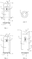
- FIG. 1 The structure disclosed by FIG. 1 except for being constructed by combining the foregoing individual parts, it may alternatively be constructed by combining the first force-receiving structure (1), the pre-stressed structure (3), and the assembled auxiliary (81) for the second force-receiving structure first, and then combining the resulting assembly with the second force-receiving structure (2).
- FIG. 4 schematically shows an embodiment of the assembled structure of FIG. 1 .
- the assembled auxiliary (81) for the second force-receiving structure is installed between the second force-receiving structure (2) and the first force-receiving structure (1) together with its pre-stressed structure (3);
- the assembled auxiliary (81) for the second force-receiving structure at its one end close to the terminal support body (5) has a flange (82), the flange (82) has its bottom provided with a contact structure (8) having higher friction damping
- the assembled auxiliary (81) for the second force-receiving structure contains therein the first force-receiving structure (1), the first force-receiving structure (1) at its one end is provided with a contact structure (7) having lower friction damping for contacting the terminal support body (5), and a pre-stressed structure (3) is provided between an opposite end of the first force-receiving structure (1) and the limiting structure (11);
- the foregoing limiting structure (11) is constructed from a top structure of the assembled auxiliary (81) for the second force-receiving structure and/or from a structure extended from a carrying end (4) combined with the second force-receiving structure (2);
- FIG. 1 and FIG. 2 The structure shown in FIG. 1 and FIG. 2 and the assembled structure shown in FIG. 4 works as described below:
- the carrier device capable of varying contact damping with pressured displacement may be formed into various structural forms sharing the same operational principles, and while some embodiments and related description will be discussed below for illustration, they are not intended to pose limitation to the present invention
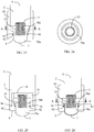
- FIG. 5 shows one embodiment of the present invention constructed from a magnetic pre-stressed device (31) and a terminal block (71) having lower friction damping.
- FIG. 6 is a schematic cross-sectional view of the structure of FIG. 5 taken along Line A-A.
- FIGs. 5 and 6 it primarily comprises the following components:
- An axial displacement limiting structure is provided between the first force-receiving structure (1) and the second force-receiving structure (2) for preventing the first force-receiving structure (1) from departing from the second force-receiving structure (2); in the present embodiment, the limiting function is realized by a guide slot (731) passing through the first force-receiving structure (1) and a pin (721) of the second force-receiving structure (2); and the foregoing axial displacement limiting structure constructed from the pin (721) and the guide slot (731) is merely one example and may be realized by alternative structures that have the same limiting capability.
- the structure disclosed by FIG. 5 except for being constructed by combining the foregoing individual parts, it may alternatively be constructed by combining the first force-receiving structure (1), the pre-stressed structure (3), and the assembled auxiliary (81) for the second force-receiving structure first, and then combining the resulting assembly with the second force-receiving structure (2);
- FIG. 7 schematically shows one embodiment of the assembled structure of FIG. 5 .
- FIG. 7 it primarily comprises the following components:
- An axial displacement limiting structure is provided between the first force-receiving structure (1) and the flange (82) of the assembled auxiliary (81) for the second force-receiving structure for preventing the first force-receiving structure (1) from departing from the assembled auxiliary (81) for the second force-receiving structure; in the present embodiment, limiting function is realized by a guide slot (731) passing through the first force-receiving structure (1) and a pin (721) of the assembled auxiliary (81) for the second force-receiving structure, and the foregoing axial displacement limiting structure constructed from the pin (721) and the guide slot (731), however, is merely one example and may be realized by alternative structures that have the same limiting capability.
- FIG. 8 shows one embodiment of the present invention constructed from a magnetic pre-stressed device (31) and a rolling wheel (72).
- FIG. 9 is a schematic cross-sectional view of the structure of FIG. 8 taken along Line A-A
- FIGs. 8 and 9 it primarily comprises the following components:
- An axial displacement limiting structure is provided between the first force-receiving structure (1) and the second force-receiving structure (2) for preventing the first force-receiving structure (1) from departing from the second force-receiving structure (2); in the present embodiment, the limiting function is realized by a guide slot (731) passing through the first force-receiving structure (1) and a pin (721) of the second force-receiving structure (2), and the foregoing axial displacement limiting structure constructed from the pin (721) and the guide slot (731), however, is merely one example and may be realized by alternative structures that have the same limiting capability.
- FIG. 8 The structure disclosed by FIG. 8 except for being constructed by combining the foregoing individual parts, it may alternatively being constructed by combining the first force-receiving structure (1), the pre-stressed structure (3), and the assembled auxiliary (81) for the second force-receiving structure first, and then combining the resulting assembly with the second force-receiving structure (2);
- FIG. 10 schematically shows one embodiment of the assembled structure of FIG. 8 .
- FIG. 10 it primarily comprises the following components:
- An axial displacement limiting structure is provided between the first force-receiving structure (1) and the flange (82) of the assembled auxiliary (81) for the second force-receiving structure for preventing the first force-receiving structure (1) from departing from the assembled auxiliary (81) for the second force-receiving structure; in the present embodiment, the limiting function is realized by a guide slot (731) passing through the first force-receiving structure (1) and a pin (721) of the assembled auxiliary (81) for the second force-receiving structure, and the foregoing axial displacement limiting structure constructed from the pin (721) and the guide slot (731), however, is merely one example and may be realized by alternative structures that have the same limiting capability.
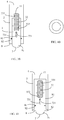
- FIG. 11 shows one embodiment of the present invention constructed from a magnetic pre-stressed device (31) and a rolling ball (73).
- FIG. 12 is a schematic cross-sectional view of the structure of FIG. 11 taken along Line A-A.
- FIG. 13 is a schematic cross-sectional view of the structure of FIG. 11 taken along Line B-B.
- FIGs. 11, 12 and 13 it primarily comprises the following components:
- An axial displacement limiting device is provided between the first force-receiving structure (1) and the second force-receiving structure (2) for preventing the first force-receiving structure (1) from departing from the second force-receiving structure (2); in the present embodiment, the limiting function is realized by a guide slot (731) passing through the first force-receiving structure (1) and a pin (721) of the second force-receiving structure (2); in the present embodiment, after the rolling ball (73) is placed in the second force-receiving structure (2), a limiting ring (730) is installed at the inner side of the opening of the second force-receiving structure (2) facing the terminal support body (5) so as to form a limiting structure that prevents the rolling ball (73) from coming off; the foregoing limiting structure for preventing both the first force-receiving structure (1) and the rolling ball (73) from coming off is merely one example and may be realized by alternative structures that have the same limiting capability.
- FIG. 11 The structure disclosed by FIG. 11 except for being constructed by combining the foregoing individual parts, it may alternatively being constructed by combining the first force-receiving structure (1), the pre-stressed structure (3), and the assembled auxiliary (81) for the second force-receiving structure first, and then combining the resulting assembly with the second force-receiving structure (2);
- FIG. 14 schematically shows one embodiment of the assembled structure of FIG. 11 .
- FIG. 14 it primarily comprises the following components:
- An axial displacement limiting structure is provided between the first force-receiving structure (1) and the flange (82) of the assembled auxiliary (81) for the second force-receiving structure for preventing the first force-receiving structure (1) from departing from the assembled auxiliary (81) for the second force-receiving structure; in the present embodiment, the limiting function is realized by a guide slot (731) passing through the first force-receiving structure (1) and a pin (721) of the assembled auxiliary (81) for the second force-receiving structure; in the present embodiment, after the rolling ball (73) is placed in the second force-receiving structure (2), a limiting ring (730) is installed at the inner side of the opening of the assembled auxiliary (81) for the second force-receiving structure facing the terminal support body (5) so as to form a limiting structure that prevents the rolling ball (73) from coming off; and the foregoing limiting structure for preventing both the first force-receiving structure (1) and the rolling ball (73) from coming off is
- FIG. 15 schematically shows one embodiment of the present invention according to FIG. 11 wherein an intermediate pad (735) is provided between the magnetic pre-stressed device (31) and the rolling ball (73).
- FIG. 16 is a schematic cross-sectional view of the structure of FIG. 15 taken along Line A-A.
- FIG. 17 is a schematic cross-sectional view of the structure of FIG. 15 taken along Line B-B.
- the structure as shown in the embodiment of FIG. 11 includes the following components:
- an intermediate pad (735) is provided between the magnetic pre-stressed device (31) and the rolling ball (73), for reducing abrasion caused by direct contact between the rolling ball (73) and the magnetic pre-stressed device (31).
- FIG. 15 The structure disclosed by FIG. 15 except for being constructed by combining the foregoing individual parts, it may alternatively being constructed by combining the first force-receiving structure (1), the pre-stressed structure (3), and the assembled auxiliary (81) for the second force-receiving structure first, and then combining the resulting assembly with the second force-receiving structure (2).
- FIG. 18 schematically shows one embodiment of the assembled structure of FIG. 15 .
- FIG. 18 it primarily comprises the following components:
- an intermediate pad (735) is provided between the magnetic pre-stressed device (31) and the rolling ball (73), for reducing abrasion caused by direct contact between the rolling ball (73) and the magnetic pre-stressed device (31).
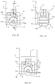
- FIG. 19 schematically shows one embodiment of the present invention constructed from a magnetic pre-stressed device (31) and a semi-spherical terminal block (70a).
- FIG. 20 is a schematic cross-sectional view of the structure of FIG. 19 taken along Line A-A.
- FIGs. 19 and 20 it primarily comprises the following components:
- the semi-spherical terminal block (70a) of the first force-receiving structure (1) is of a semi-spherical structure, with its slower side having a spherical projecting end facing the terminal support body (5) constructed as a contact structure (7) having lower friction damping, and with its upper end provided with the permanent magnet composing the magnetic pre-stressed device (31), an outward-expanding annular flange structure (70b) is provided at its upper periphery for engaging with the inwardly-retracted flange (84) of the outer auxiliary (83) for second force-receiving structure thereby preventing disengagement;
- FIG. 19 The structure disclosed by FIG. 19 except for being constructed by combining the foregoing individual parts, it may alternatively being constructed by combining the first force-receiving structure (1), the pre-stressed structure (3), and the assembled auxiliary (81) for the second force-receiving structure first, and then combining the resulting assembly with the second force-receiving structure (2);
- FIG. 21 schematically shows one embodiment of the assembled structure of FIG. 19 .
- FIG. 21 it primarily comprises the following components:
- the semi-spherical terminal block (70a) of the first force-receiving structure (1) is of a semi-spherical structure, with its slower side having a spherical projecting end facing the terminal support body (5) constructed as a contact structure (7) having lower friction damping, and with its upper end provided with the permanent magnet composing the magnetic pre-stressed device (31), an outward-expanding annular flange structure (70b) is provided at its upper periphery for engaging with the inwardly-retracted flange (84) of the flange (82) of the assembled auxiliary (81) for the second force-receiving structure thereby preventing disengagement;
- the contact structure (7) having lower friction damping of the semi-spherical terminal block (70a) When the pressure between the carrying end (4) and the terminal support body (5) contacted by the contact structure (7) having lower friction damping of the semi-spherical terminal block (70a) is greater than the set value, the semi-spherical terminal block (70a) is pressured and displaced, so the contact structure (7) having lower friction damping and the contact structure (8) having higher friction damping of the second force-receiving structure (2) jointly contact the terminal support body (5).
- the semi-spherical terminal block (70a) and the outward-expanding annular flange structure (70b) may be constructed from a semi-spherical cup-shaped structure (70c), the semi-spherical cup-shaped structure (70c) has an outwardly-extended annular sheet (70d), the foregoing semi-spherical cup-shaped structure (70c) may be used instead of the semi-spherical terminal block (70a), and the outwardly-extended annular sheet (70d) can be in place of the outward-expanding annular flange structure (70b) at the upper periphery of the semi-spherical terminal block (70a).
- FIG. 22 schematically shows one embodiment of the structure of FIG. 19 , wherein the semi-spherical terminal block (70a) is replaced with a semi-spherical cup-shaped structure (70c).
- FIG. 23 schematically shows one embodiment of the present invention constructed from a spiral spring pre-stressed device (33) and a semi-spherical terminal block (70a).
- FIG. 24 is a schematic cross-sectional view of the structure of FIG. 23 taken along Line A-A.
- FIGs. 23 and 24 it primarily comprises the following components:
- the semi-spherical terminal block (70a) of the first force-receiving structure (1) is of a semi-spherical structure, with its slower side having a spherical projecting end facing the terminal support body (5) constructed as a contact structure (7) having lower friction damping, and with its upper end provided with the spiral spring pre-stressed device (33), an outward-expanding annular flange structure (70b) is provided at its upper periphery for engaging with the inwardly-retracted flange (84) of the outer auxiliary (83) for second force-receiving structure thereby preventing disengagement;
- FIG. 23 The structure disclosed by FIG. 23 except for being constructed by combining the foregoing individual parts, it may alternatively being constructed by combining the first force-receiving structure (1), the pre-stressed structure (3), and the assembled auxiliary (81) for the second force-receiving structure first, and then combining the resulting assembly with the second force-receiving structure (2);
- FIG. 25 schematically shows one embodiment of the assembled structure of FIG. 23 .
- FIG. 25 it primarily comprises the following components:
- the semi-spherical terminal block (70a) of the first force-receiving structure (1) is of a semi-spherical structure, with its slower side having a spherical projecting end facing the terminal support body (5) constructed as a contact structure (7) having lower friction damping, and with its upper end provided with the spiral spring pre-stressed device (33), an outward-expanding annular flange structure (70b) is provided at its upper periphery for engaging with the inwardly-retracted flange (84) of the flange (82) of the assembled auxiliary (81) for the second force-receiving structure thereby preventing disengagement;
- the contact structure (7) having lower friction damping of the semi-spherical terminal block (70a) When the pressure between the carrying end (4) and the terminal support body (5) contacted by the contact structure (7) having lower friction damping of the semi-spherical terminal block (70a) is greater than the set value, the semi-spherical terminal block (70a) is pressured and displaced, so the contact structure (7) having lower friction damping and the contact structure (8) having higher friction damping of the second force-receiving structure (2) jointly contact the terminal support body (5).
- the semi-spherical terminal block (70a) and the outward-expanding annular flange structure (70b) may be constructed from a semi-spherical cup-shaped structure (70c), the semi-spherical cup-shaped structure (70c) has an outwardly-extended annular sheet (70d), the foregoing semi-spherical cup-shaped structure (70c) may be used instead of the semi-spherical terminal block (70a), and the outwardly-extended annular sheet (70d) can be in place of the outward-expanding annular flange structure (70b) at the upper periphery of the semi-spherical terminal block (70a).
- FIG. 26 schematically shows one embodiment wherein the semi-spherical terminal block (70a) of FIG. 23 is replaced with a semi-spherical cup-shaped structure (70c).
- FIG. 27 schematically shows one embodiment of the present invention constructed from a spiral spring pre-stressed device (33) and a terminal block (71) having lower friction damping.
- FIG. 28 is a schematic cross-sectional view of the structure of FIG. 27 taken along Line A-A.
- FIG. 27 and 28 it primarily comprises the following components:
- An axial displacement limiting device is provided between the first force-receiving structure (1) and the second force-receiving structure (2) for preventing the terminal block (71) having lower friction damping of the first force-receiving structure (1) from departing from the second force-receiving structure (2);
- the axial displacement limiting structure is realized by screwing two ends of a spiral spring pre-stressed device (33) with a recess (331) at the limiting structure (11) extended from and linked to the second force-receiving structure (2) and a recess (332) at the upper part of the terminal block (71) having lower friction damping, respectively, for preventing the terminal block (71) having lower friction damping from departing from the second force-receiving structure (2)
- the foregoing limiting structure for preventing both the first force-receiving structure (1) and the terminal block (71) from coming off is merely one example, alternatively, it may be realized by a guide slot (731) passing through the first force-receiving structure (1) and a
- the structure disclosed in FIG. 27 except for being constructed by combining the foregoing individual parts, it may alternatively being constructed by combining the first force-receiving structure (1), the pre-stressed structure (3), and the assembled auxiliary (81) for the second force-receiving structure first, and then combining the resulting assembly with the second force-receiving structure (2);
- FIG. 29 schematically shows one embodiment of the assembled structure of FIG. 27 .
- FIG. 29 it primarily comprises the following components:
- An axial displacement limiting structure is provided between the first force-receiving structure (1) and the flange (82) of the assembled auxiliary (81) for the second force-receiving structure for preventing the first force-receiving structure (1) from departing from the assembled auxiliary (81) for the second force-receiving structure; in the present embodiment, the axial displacement limiting structure is realized by screwing two ends of a spiral spring pre-stressed device (33) with a recess (331) of the limiting structure (11) of the second force-receiving structure (2) and a recess (332) at the upper part of the terminal block (71) having lower friction damping, respectively, for preventing the terminal block (71) having lower friction damping from departing from the second force-receiving structure (2), the foregoing limiting structure for preventing both the first force-receiving structure (1) and the terminal block (71) from coming off is merely one example, alternatively, it may be realized by a guide slot (731) passing through the first force-receiving
- FIG. 30 schematically shows one embodiment of the present invention constructed from a spiral spring pre-stressed device (33) and a rolling ball (73).
- FIG. 31 is a bottom view according to FIG. 30 .
- FIGs. 30 and 31 it primarily comprises the following components:
- the rolling ball (73) of the first force-receiving structure (1) is of a spherical structure
- the spiral spring pre-stressed device (33) is installed at the upper side of the rolling ball (73)
- the rolling ball (73) is limited by the inwardly-retracted flange (84) of the outer auxiliary (83) for second force-receiving structure for preventing it from coming off;
- FIG. 30 except for being constructed by combining the foregoing individual parts, it may alternatively being constructed by combining the first force-receiving structure (1), the pre-stressed structure (3), and the assembled auxiliary (81) for the second force-receiving structure first, and then combining the resulting assembly with the second force-receiving structure (2);
- FIG. 32 schematically shows one embodiment of the assembled structure of FIG. 30 .
- FIG. 32 it primarily comprises the following components:
- FIG. 33 schematically shows one embodiment of the present invention constructed from a spiral spring pre-stressed device (33), an intermediate pad (735), and a rolling ball (73).
- FIG. 34 is a bottom view according to FIG. 33 .
- FIGs. 33 and 34 it primarily comprises the following components:
- the rolling ball (73) of the first force-receiving structure (1) is of a spherical structure, an intermediate pad (735) is provided at the upper side of the rolling ball (73), and the spiral spring pre-stressed device (33) is installed thereon; the rolling ball (73) is limited by the inwardly-retracted flange (84) of the outer auxiliary (83) for second force-receiving structure, for preventing it from coming off;
- FIG. 33 except for being constructed by combining the foregoing individual parts, it may alternatively being constructed by combining the first force-receiving structure (1), the pre-stressed structure (3), and the assembled auxiliary (81) for the second force-receiving structure first, and then combining the resulting assembly with the second force-receiving structure (2);
- FIG. 35 schematically shows one embodiment of the assembled structure of FIG. 33 .
- FIG. 35 it primarily comprises the following components:
- FIG. 36 schematically shows one embodiment of the present invention constructed from a U-shaped leaf spring (34) with a concaved contact surface and a rolling ball (73).
- FIG. 37 is a schematic cross-sectional view of the structure of FIG. 36 taken along Line A-A.
- FIGs. 36 and 37 it primarily comprises the following components:
- the rolling ball (73) of the first force-receiving structure (1) is of a spherical structure, the rolling ball (73) at its upper side is provided with a U-shaped leaf spring (34) with a concaved contact surface, and the rolling ball (73) is limited by the inwardly-retracted flange (84) of the outer auxiliary (83) for second force-receiving structure, for preventing it from coming off;
- FIG. 36 The structure disclosed by FIG. 36 except for being constructed by combining the foregoing individual parts, it may alternatively being constructed by combining the first force-receiving structure (1), the pre-stressed structure (3), and the assembled auxiliary (81) for the second force-receiving structure first, and then combining the resulting assembly with the second force-receiving structure (2);
- FIG. 38 schematically shows one embodiment of the assembled structure of FIG. 36 .
- FIG. 38 it primarily comprises the following components:
- FIG. 39 schematically shows one embodiment of the present invention constructed from an elastic material pre-stressed device (32) and a terminal block (71) having lower friction damping.
- FIG. 40 is a bottom view according to FIG. 39 .
- FIGs. 39 and 40 it primarily comprises the following components:
- An axial displacement limiting device is provided between the first force-receiving structure (1) and the second force-receiving structure (2) for preventing the terminal block (71) having lower friction damping of the first force-receiving structure (1) from departing from the second force-receiving structure (2);
- the axial displacement limiting structure is realized by screwing two ends of an elastic material pre-stressed device (32) with a recess (331) at the limiting structure (11) and a recess (332) at the upper part of the terminal block (71) having lower friction damping, respectively, for preventing the terminal block (71) having lower friction damping from departing from the second force-receiving structure (2);
- the foregoing limiting structure for preventing both the first force-receiving structure (1) and the terminal block (71) having lower friction damping from coming off is merely one example, alternatively, it may be realized by a guide slot (731) passing through the first force-receiving structure (1) and a pin (721) of the second force-rece
- FIG. 39 The structure disclosed in FIG. 39 except for being constructed by combining the foregoing individual parts, it my alternatively being constructed by combining the first force-receiving structure (1), the pre-stressed structure (3), and the assembled auxiliary (81) for the second force-receiving structure first, and then combining the resulting assembly with the second force-receiving structure (2);
- FIG. 41 schematically shows one embodiment of the assembled structure of FIG. 39 .
- FIG. 41 it primarily comprises the following components:
- An axial displacement limiting structure is provided between the first force-receiving structure (1) and the flange (82) of the assembled auxiliary (81) for the second force-receiving structure for preventing the first force-receiving structure (1) from departing from the assembled auxiliary (81) for the second force-receiving structure; in the present embodiment, the axial displacement limiting structure is realized by screwing two ends of an elastic material pre-stress device (32) with a recess (331) of the limiting structure (11) of the second force-receiving structure (2) and a recess (332) at the upper part of the terminal block (71) having lower friction damping, respectively, for preventing the terminal block (71) having lower friction damping from departing from the second force-receiving structure (2), the foregoing limiting structure for preventing both the first force-receiving structure (1) and the terminal block (71) from coming off is merely one example, Alternatively, it may be realized by a guide slot (731) passing through the first force-receiving structure (1) and
- FIG. 42 schematically shows one embodiment of the present invention constructed from a magnetic pre-stressed device (31) and a rolling wheel (72), which is of a one-side swinging structure.
- FIG. 43 is a schematic cross-sectional view of the structure of FIG. 42 taken along Line A-A.
- FIGs. 42 and 43 it primarily comprises the following components:
- FIG. 42 The structure disclosed by FIG. 42 except for being constructed by combining the foregoing individual parts, it may alternatively being constructed by combining the first force-receiving structure (1), the pre-stressed structure (3), and the assembled auxiliary (81) for the second force-receiving structure first, and then combining the resulting assembly with the second force-receiving structure (2);
- FIG. 44 schematically shows one embodiment of the assembled structure of FIG. 42 .
- FIG. 44 it primarily comprises the following components:
- FIG. 45 schematically shows one embodiment of the present invention constructed from a U-shaped leaf spring pre-stressed device (35) and a single rolling wheel (72).
- FIG. 46 is a schematic cross-sectional view of the structure of FIG. 45 taken along Line A-A.
- FIGs. 45 and 46 it primarily comprises the following components:
- the structure disclosed by FIG. 45 except for being constructed by combining the foregoing individual parts, it may alternatively be constructed by combining the first force-receiving structure (1), the pre-stressed structure (3), and the assembled auxiliary (81) for the second force-receiving structure first, and then combining the resulting assembly with the second force-receiving structure (2);
- FIG. 47 schematically shows an embodiment of the assembled structure of FIG. 45 .
- FIG. 47 it primarily comprises the following components:
- FIG. 48 schematically shows one embodiment of the present invention constructed from a spiral spring pre-stressed device (33) and a single rolling wheel (72).
- FIG. 49 is a bottom view according to FIG. 48 .
- FIGs. 48 and 49 it primarily comprises the following components:
- An axial displacement limiting structure is provided between the first force-receiving structure (1) and the second force-receiving structure (2) for preventing the first force-receiving structure (1) from departing from the second force-receiving structure (2), in the present embodiment, the limiting function is realized by a shaft (723) provided on the first force-receiving structure (1) passing through a guide slot (732) of the second force-receiving structure (2); the foregoing axial displacement limiting structure constructed from the shaft (723) and the guide slot (732), however, is merely one example and may be realized by alternative structures that have the same limiting capability.
- FIG. 48 The structure disclosed by FIG. 48 except for being constructed by combining the foregoing individual parts, it may alternatively be constructed by combining the first force-receiving structure (1), the pre-stressed structure (3), and the assembled auxiliary (81) for the second force-receiving structure first, and then combining the resulting assembly with the second force-receiving structure (2);
- FIG. 50 schematically shows one embodiment of the assembled structure of FIG. 48 .
- FIG. 50 it primarily comprises the following components:
- An axial displacement limiting structure is provided between the first force-receiving structure (1) and the flange (82) of the assembled auxiliary (81) for the second force-receiving structure for preventing the first force-receiving structure (1) from departing from the assembled auxiliary (81) for the second force-receiving structure; in the present embodiment, the limiting function is realized by a guide slot (732) passing through the second force-receiving structure (2) and a shaft (723) of the assembled auxiliary (81) for the second force-receiving structure, and the foregoing axial displacement limiting structure constructed from the shaft (723) and the guide slot (732), however, is merely one example and may be realized by alternative structures that have the same limiting capability.
- FIG. 51 schematically shows one embodiment of the present invention constructed from a spiral spring pre-stressed device (33) and two rolling wheels (72'), (72").
- FIG. 52 is a bottom view according to FIG. 51 .
- FIGs. 51 and 52 it primarily comprises the following components:
- An axial displacement limiting structure is provided between the first force-receiving structure (1) and the second force-receiving structure (2) for preventing the first force-receiving structure (1) from departing from the second force-receiving structure (2), in the present embodiment, the limiting function is realized by a shaft (723) of the first force-receiving structure (1) passing through a guide slot (732) of the second force-receiving structure (2), and the foregoing displacement limiting structure constructed from the shaft (723) and the guide slot (732), however, is merely one example and may be realized by alternative structures that have the same limiting capability.
- FIG. 51 The structure disclosed by FIG. 51 except for being constructed by combining the foregoing individual parts, it may alternatively be constructed by combining the first force-receiving structure (1), the pre-stressed structure (3), and the assembled auxiliary (81) for the second force-receiving structure first, and then combining the resulting assembly with the second force-receiving structure (2).
- FIG. 53 schematically shows one embodiment of the assembled structure of FIG. 51 .
- FIG. 53 it primarily comprises the following components:
- An axial displacement limiting structure is provided between the first force-receiving structure (1) and the flange (82) of the assembled auxiliary (81) for the second force-receiving structure for preventing the first force-receiving structure (1) from departing from the assembled auxiliary (81) for the second force-receiving structure
- the limiting function is realized by a guide slot (732) passing through the second force-receiving structure (2) and a shaft (723) of the assembled auxiliary (81) for the second force-receiving structure, and the foregoing axial displacement limiting structure constructed from the shaft (723) and the guide slot (732) is, however, merely one example and may be realized by alternative structures that have the same limiting capability.
- the pre-stressed structure (3) that generates displacement corresponding to the pressure it receives in addition to the foregoing structures providing pressured displacement using energy stored as compressive prestress, it may have structures providing pressured displacement using energy stored as expansive prestress, such as those described in the embodiments below.
- FIG. 54 is the first schematic structural embodiment of the present invention showing the pre-stressed structure (3) providing pressured displacement using energy stored as expansive prestress.
- the magnetic pre-stressed device (31) made of the permanent magnets that are arranged to have mutual repellence mutual as shown in FIG. 5 is replaced with a structure wherein the permanent magnet (311) connected to the terminal block (71) having lower friction damping through the guide rod (111) work with the magnetic conductive member (312) provided at the second force-receiving structure (2) to generate mutual attraction, which pushes the terminal block (71) having lower friction damping to be exposed outside the contact structure (8) having higher friction damping of the second force-receiving structure (2), and wherein when the terminal block (71) having lower friction damping is pressed and performs retracting displacement, the magnetic attraction between the permanent magnet (311) and the magnetic conductive member (312) is stored for providing a required pre-stressed force for the terminal block (71) having lower friction damping to return.
- FIG. 55 is the second schematic structural embodiment of the present invention showing the pre-stressed structure (3) providing pressured displacement using energy stored as expansive prestress.
- the spiral spring pre-stressed device (33) of FIG. 23 has one end thereof received in the spring positioning hole (115) at the upper end of the guide rod (111), and has an opposite end thereof sandwiched between the stepped structure (85) of the outer auxiliary (83) for second force-receiving structure and the second force-receiving structure (2), the guide rod (111) has its lower end connected to the semi-spherical terminal block (70a), and the pulling force from the spiral spring pre-stressed device (33) exposes the semi-spherical terminal block (70a) outside the contact structure (8) having higher friction damping of the second force-receiving structure (2), and when the semi-spherical terminal block (70a) is pressed and performs retracting displacement, the spiral spring pre-stressed device (33) is in a pre-stressed state storing required energy for the semi-spherical terminal block (70a) to return.
- FIG. 56 is the third schematic structural embodiment of the present invention showing the pre-stressed structure (3) providing pressured displacement using energy stored as expansive prestress.
- the spiral spring pre-stressed device (33) of FIG. 27 is installed inside the upper part of the terminal block (71) having lower friction damping, the upper end of the spiral spring pre-stressed device (33) is fixed to the upper part of the terminal block (71) having lower friction damping by means of the pin (724), the lower end of the spiral spring pre-stressed device (33) passes through the guide slot (731) of the terminal block (71) having lower friction damping and the second force-receiving structure (2) by means of another pin (721), the pulling force of the spiral spring pre-stressed device (33) exposes the terminal block (71) having lower friction damping outside the contact structure (8) having higher friction damping of the second force-receiving structure (2), and when the terminal block (71) having lower friction damping is pressed and performs retracting displacement, the spiral spring pre-stressed device (33) is in a pre-stressed state storing required energy for the terminal block (71) having lower friction damping to return.
- FIG. 57 is the fourth schematic structural embodiment of the present invention showing the pre-stressed structure (3) providing pressured displacement using energy stored as expansive prestress.
- the U-shaped leaf spring (34) of FIG. 36 is replaced with a leaf spring that has preloading capability
- the leaf spring fastening side (362) is sandwiched between the outer auxiliary (83) for second force-receiving structure and the combining stepped segment of the second force-receiving structure (2)
- the leaf spring preloaded sheet (361) applies prestress to the rolling ball (73) so as to expose the rolling ball (73) outside the contact structure (8) having higher friction damping of the outer auxiliary (83) for second force-receiving structure, and when the rolling ball (73) is pressed and performs retracting displacement, the leaf spring preloaded sheet (361) is in a pre-stressed state storing required energy for the rolling ball (73) to return.
- FIG. 58 is the fifth schematic structural embodiment of the present invention showing the pre-stressed structure (3) providing pressured displacement using energy stored as expansive prestress.
- the magnetic pre-stressed device (31) of FIG. 42 is replaced with a permanent magnet (311) and a magnetic conductive member (312), the magnetic conductive member (312) is installed inside the second force-receiving structure (2), and the permanent magnet (311) is installed at one side of the wheel arm (722) facing the magnetic conductive member (312), so as to provide magnetic attraction that drives the wheel arm (722) to swing and in turn expose the rolling wheel (72) outside the contact structure (8) having higher friction damping of the second force-receiving structure (2), and when the rolling wheel (72) is pressed and performs retracting displacement, the magnetic attraction between the permanent magnet (311) and the magnetic conductive member (312) is in a pre-stressed state storing required energy for the rolling wheel (72) to return.
- FIG. 59 is the sixth schematic structural embodiment of the present invention showing the pre-stressed structure (3) providing pressured displacement using energy stored as expansive prestress.
- the U-shaped leaf spring pre-stressed device (35) of the FIG. 45 is replaced with the preloaded spring (37), the preloaded spring (37) has its one end attached to and positioned on the second force-receiving structure (2), and has its opposite end being pressured by the wheel arm (722) that swings against the pin (721), so as to expose the rolling wheel (72) outside the contact structure (8) having higher friction damping of the second force-receiving structure (2), and when the rolling wheel (72) is pressed and performs retracting displacement, the preloaded spring (37) is in a pre-stressed state storing required energy for the rolling wheel (72) to return.
- FIG. 60 is the seventh schematic structural embodiment of the present invention showing the pre-stressed structure (3) providing pressured displacement using energy stored as expansive prestress.
- a structural block (333) is installed in the second force-receiving structure (2) of the structure shown in FIG. 48 , the structural block (333) allows the guide rod (111) to pass therethrough and perform axial displacement therein, the spiral spring pre-stressed device (33) has its one end received in the spring positioning hole (115) at the upper end of the guide rod (111), the spiral spring pre-stressed device (33) has its opposite end received in the spring positioning hole (116) of the structural block (333), the spiral spring pre-stressed device (33) exerts a pulling force on the spring positioning hole (115) at the upper end of the guide rod (111) so as to expose the rolling wheel (72) outside the contact structure (8) having higher friction damping of the second force-receiving structure (2), and when the rolling wheel (72) is pressed and performs retracting displacement, the spiral spring pre-stressed device (33) is in a pre-stressed state storing required energy for the rolling wheel (72) to return.
- the carrier device capable of varying contact damping with pressured displacement of the present invention maybe combined with traditional interface mechanisms for enriched applications or for lengthened service life. A relevant example is discussed below.
- FIG. 61 schematically shows an embodiment that the present invention is provided with the axial rotating structure (21).
- the structure primarily includes the following components:
- the axial rotating structure (21) is constructed from:
- the carrier device capable of varying contact damping with pressured displacement of the present invention may form a sealing function through the combination of a conventional sealing ring (91) and an annular sealing slot (92) between the first force-receiving structure (1) and the second force-receiving structure (2), between the first force-receiving structure (1) and the assembled auxiliary (81) for the second force-receiving structure, or between the semi-spherical terminal block (70a)/annular flange structure (70b)/semi-spherical cup-shaped structure (70c)/outwardly-extended annular sheet (70d)/terminal block (71) having lower friction damping and the second force-receiving structure (2), thereby lengthening its service life.
- a conventional sealing ring (91) and an annular sealing slot (92) between the first force-receiving structure (1) and the second force-receiving structure (2), between the first force-receiving structure (1) and the assembled auxiliary (81) for the second force-recei
Applications Claiming Priority (1)
| Application Number | Priority Date | Filing Date | Title |
|---|---|---|---|
| US15/159,962 US10106005B2 (en) | 2016-05-20 | 2016-05-20 | Carrier device capable of varying contact damping with pressured displacement |
Publications (1)
| Publication Number | Publication Date |
|---|---|
| EP3245898A1 true EP3245898A1 (de) | 2017-11-22 |
Family
ID=60328990
Family Applications (1)
| Application Number | Title | Priority Date | Filing Date |
|---|---|---|---|
| EP17172056.8A Pending EP3245898A1 (de) | 2016-05-20 | 2017-05-19 | Trägervorrichtung mit fähigkeit zum ändern der kontaktdämpfung mit druckverdrängung |
Country Status (10)
| Country | Link |
|---|---|
| US (1) | US10106005B2 (de) |
| EP (1) | EP3245898A1 (de) |
| JP (1) | JP7013625B2 (de) |
| KR (1) | KR102351173B1 (de) |
| CN (1) | CN107448533B (de) |
| AU (1) | AU2017203381B2 (de) |
| BR (1) | BR102017010625A2 (de) |
| CA (1) | CA2967423A1 (de) |
| SG (1) | SG10201703984VA (de) |
| TW (1) | TWI774676B (de) |
Cited By (1)
| Publication number | Priority date | Publication date | Assignee | Title |
|---|---|---|---|---|
| IT201900020088A1 (it) * | 2019-10-30 | 2021-04-30 | F A C S R L | Cancello scorrevole articolato e dispositivo di scorrimento a terra per cancelli scorrevoli articolati |
Families Citing this family (10)
| Publication number | Priority date | Publication date | Assignee | Title |
|---|---|---|---|---|
| CN107559543B (zh) * | 2017-09-08 | 2020-10-30 | 中国交通建设股份有限公司 | 一种承载结构件、支座、接头组件以及管节组件 |
| JP7131567B2 (ja) | 2017-10-25 | 2022-09-06 | 日本電気株式会社 | 生体認証装置、生体認証システム、生体認証方法、および生体認証プログラム |
| KR102003708B1 (ko) | 2018-08-02 | 2019-07-25 | (주)누리 | 의자 이동장치 |
| CN109230421A (zh) * | 2018-09-04 | 2019-01-18 | 东莞倍力扣金属制品有限公司 | 扣件转载装置 |
| CN109363373B (zh) * | 2018-10-27 | 2020-10-30 | 安徽省高雅家居有限公司 | 一种防尘土鞋柜 |
| CN109334818B (zh) * | 2018-11-29 | 2024-01-23 | 杭叉集团股份有限公司 | 一种磁引导传感器安装装置及其系统 |
| IT201900006439A1 (it) * | 2019-04-29 | 2020-10-29 | Schedoni Luxury Goods S R L | Dispositivo di supporto per rotelle di contenitori trasportabili, quali trolley o simili |
| KR102566356B1 (ko) * | 2021-09-13 | 2023-08-10 | 최용해 | 캐스터 모듈 |
| CN113847529A (zh) * | 2021-09-28 | 2021-12-28 | 向帆 | 一种球关节机构 |
| DE102022203346A1 (de) * | 2022-04-05 | 2023-10-05 | Hyundai Motor Company | Radträger für eine aufhängung eines kraftfahrzeugs |
Citations (6)
| Publication number | Priority date | Publication date | Assignee | Title |
|---|---|---|---|---|
| US4660994A (en) * | 1986-04-23 | 1987-04-28 | Camillo Masciarelli | Anti-friction element |
| US5350151A (en) * | 1991-12-09 | 1994-09-27 | Matsushita Electric Industrial Co., Ltd. | Load supporting apparatus |
| US6594856B1 (en) * | 2002-03-07 | 2003-07-22 | Hema Cherukuri | Pivotal roller mechanism |
| US7992584B1 (en) * | 2010-04-20 | 2011-08-09 | Bernardo Birnbaum | Walker with retractable wheels |
| WO2015118492A1 (en) * | 2014-02-06 | 2015-08-13 | Wheel.Me As | Rolling device, a piece of furniture comprising a rolling device and a use of the rolling device |
| EP2949307A1 (de) * | 2013-01-25 | 2015-12-02 | Fujian Secure Medical Technology Co. Ltd | Gehhilfevorrichtung |
Family Cites Families (22)
| Publication number | Priority date | Publication date | Assignee | Title |
|---|---|---|---|---|
| US5248011A (en) * | 1992-01-23 | 1993-09-28 | Richards Donald C | Three wheeled vehicle having driven front wheels and steerable rear wheel |
| JPH068006U (ja) * | 1992-07-09 | 1994-02-01 | 株式会社シモオカ | キャスタ |
| JP3056036B2 (ja) * | 1994-02-16 | 2000-06-26 | フランスベッド株式会社 | 家 具 |
| JP2928112B2 (ja) * | 1994-11-02 | 1999-08-03 | 株式会社ナンシン | ベッド用脚座 |
| JPH08216605A (ja) * | 1995-02-20 | 1996-08-27 | Itoki Crebio Corp | キャスター |
| JPH08216606A (ja) * | 1995-02-20 | 1996-08-27 | Itoki Crebio Corp | キャスター |
| JP3045912U (ja) * | 1997-08-01 | 1998-02-20 | 秋 金 王 | 椅子キャスター |
| KR200342099Y1 (ko) * | 2003-11-27 | 2004-02-14 | 이영상 | 볼캐스터의 구조 |
| DE102009025227A1 (de) * | 2009-06-17 | 2010-12-30 | Audi Ag | Radaufhängung für die hinteren Räder von Kraftfahrzeugen |
| KR20110006382U (ko) * | 2009-12-17 | 2011-06-23 | 이효재 | 가구 이송용 볼 트랜스퍼 |
| KR101861391B1 (ko) * | 2010-05-28 | 2018-07-02 | 존 빅터 가노 | 전방향 휠 조립체 및 전방향 차량 |
| KR200461006Y1 (ko) * | 2011-12-26 | 2012-06-21 | 최준호 | 가구용 구름다리 굽 |
| US9108665B2 (en) * | 2012-03-05 | 2015-08-18 | Hitachi, Ltd. | Moving mechanism |
| JP5961020B2 (ja) * | 2012-03-21 | 2016-08-02 | Kyb株式会社 | 懸架装置 |
| MX2015003686A (es) * | 2012-09-24 | 2015-06-15 | Yamaha Motor Co Ltd | Vehiculo. |
| CN103925321B (zh) * | 2013-01-15 | 2017-05-31 | 青岛海尔洗衣机有限公司 | 一种变阻尼减震器及装有该减震器的洗衣机 |
| JP6157927B2 (ja) * | 2013-05-24 | 2017-07-05 | コンビ株式会社 | 乳母車用のキャスターおよび当該キャスターを取り付けられた乳母車 |
| DE102013010298A1 (de) * | 2013-06-19 | 2014-12-24 | Bomag Gmbh | Baumaschine, insbesondere Straßenfräse, und Verfahren zum Ausgleichen von Bodenunebenheiten für eine solche Baumaschine |
| US9296273B2 (en) * | 2013-10-14 | 2016-03-29 | Agco Corporation | Machine suspension and height adjustment |
| JP2016000567A (ja) * | 2014-06-11 | 2016-01-07 | Kyb株式会社 | キャスタユニット |
| TWM501957U (zh) * | 2015-01-29 | 2015-06-01 | Honyi Trading Co Ltd | 具定向結構的腳輪裝置 |
| TWM520475U (zh) * | 2015-10-30 | 2016-04-21 | qi-hou Wu | 煞止腳輪之結構改良 |
-
2016
- 2016-05-20 US US15/159,962 patent/US10106005B2/en active Active
-
2017
- 2017-05-15 CA CA2967423A patent/CA2967423A1/en active Pending
- 2017-05-16 SG SG10201703984VA patent/SG10201703984VA/en unknown
- 2017-05-17 JP JP2017098381A patent/JP7013625B2/ja active Active
- 2017-05-18 KR KR1020170061572A patent/KR102351173B1/ko active IP Right Grant
- 2017-05-19 BR BR102017010625-0A patent/BR102017010625A2/pt unknown
- 2017-05-19 CN CN201710358608.5A patent/CN107448533B/zh active Active
- 2017-05-19 AU AU2017203381A patent/AU2017203381B2/en active Active
- 2017-05-19 TW TW106116553A patent/TWI774676B/zh active
- 2017-05-19 EP EP17172056.8A patent/EP3245898A1/de active Pending
Patent Citations (6)
| Publication number | Priority date | Publication date | Assignee | Title |
|---|---|---|---|---|
| US4660994A (en) * | 1986-04-23 | 1987-04-28 | Camillo Masciarelli | Anti-friction element |
| US5350151A (en) * | 1991-12-09 | 1994-09-27 | Matsushita Electric Industrial Co., Ltd. | Load supporting apparatus |
| US6594856B1 (en) * | 2002-03-07 | 2003-07-22 | Hema Cherukuri | Pivotal roller mechanism |
| US7992584B1 (en) * | 2010-04-20 | 2011-08-09 | Bernardo Birnbaum | Walker with retractable wheels |
| EP2949307A1 (de) * | 2013-01-25 | 2015-12-02 | Fujian Secure Medical Technology Co. Ltd | Gehhilfevorrichtung |
| WO2015118492A1 (en) * | 2014-02-06 | 2015-08-13 | Wheel.Me As | Rolling device, a piece of furniture comprising a rolling device and a use of the rolling device |
Cited By (2)
| Publication number | Priority date | Publication date | Assignee | Title |
|---|---|---|---|---|
| IT201900020088A1 (it) * | 2019-10-30 | 2021-04-30 | F A C S R L | Cancello scorrevole articolato e dispositivo di scorrimento a terra per cancelli scorrevoli articolati |
| WO2021084426A1 (en) * | 2019-10-30 | 2021-05-06 | F A C S.R.L. | Articulated sliding gate and ground sliding device for articulated sliding gates |
Also Published As
| Publication number | Publication date |
|---|---|
| CN107448533B (zh) | 2021-09-24 |
| CA2967423A1 (en) | 2017-11-20 |
| US20170334258A1 (en) | 2017-11-23 |
| BR102017010625A2 (pt) | 2017-12-05 |
| AU2017203381B2 (en) | 2022-12-01 |
| SG10201703984VA (en) | 2017-12-28 |
| US10106005B2 (en) | 2018-10-23 |
| TW201741572A (zh) | 2017-12-01 |
| JP7013625B2 (ja) | 2022-02-15 |
| TWI774676B (zh) | 2022-08-21 |
| JP2017206243A (ja) | 2017-11-24 |
| KR20170131261A (ko) | 2017-11-29 |
| KR102351173B1 (ko) | 2022-01-13 |
| CN107448533A (zh) | 2017-12-08 |
| AU2017203381A1 (en) | 2017-12-07 |
Similar Documents
| Publication | Publication Date | Title |
|---|---|---|
| EP3245898A1 (de) | Trägervorrichtung mit fähigkeit zum ändern der kontaktdämpfung mit druckverdrängung | |
| US8991675B2 (en) | Dynamic clutch apparatus for electrical nail gun | |
| US6923667B1 (en) | Rotary adapter | |
| JP2013512397A (ja) | 弾性軸受マウント | |
| CN109469698B (zh) | 单点回转限位机构 | |
| JP4310549B2 (ja) | 構造体用耐震システム | |
| KR20140056798A (ko) | 덮개판과 지지대가 구비된 구조물의 마찰 진자받침 | |
| CN113696995B (zh) | 具有着陆缓冲功能的月面足式机器人高性能行走足 | |
| CN216386335U (zh) | 一种舵机弹性负载 | |
| CN203294080U (zh) | 支腿座、支腿及工程机械 | |
| KR20080006155U (ko) | 의자방향 복원장치 | |
| CN102045050B (zh) | 无触点开关 | |
| CN212337774U (zh) | 带旋转底座升降气缸 | |
| US11142935B2 (en) | Sliding stop switch and wearable chair including the same | |
| KR101650124B1 (ko) | 복합하중에 유리한 슬라이드 장치 | |
| US20170361652A1 (en) | Rolling device, especially for furniture, luggage cases and the like | |
| JP4126436B2 (ja) | 構造体用耐震システム及びこのシステムに利用可能な耐震連結装置 | |
| US6877185B2 (en) | Caster device for movably supporting a load | |
| CN2603274Y (zh) | 能够自由移动的支撑装置 | |
| CN210661118U (zh) | 一种单向轴承 | |
| CN113154191B (zh) | 支撑架及应用其的显示设备 | |
| CN201896812U (zh) | 液压油缸或气缸用缓冲锁紧定位装置 | |
| CN107246437A (zh) | 一种一体式支撑组件 | |
| CN102697276B (zh) | 提手 | |
| CN211626288U (zh) | 一种便于携带的防爆球 |
Legal Events
| Date | Code | Title | Description |
|---|---|---|---|
| PUAI | Public reference made under article 153(3) epc to a published international application that has entered the european phase |
Free format text: ORIGINAL CODE: 0009012 |
|
| STAA | Information on the status of an ep patent application or granted ep patent |
Free format text: STATUS: THE APPLICATION HAS BEEN PUBLISHED |
|
| AK | Designated contracting states |
Kind code of ref document: A1 Designated state(s): AL AT BE BG CH CY CZ DE DK EE ES FI FR GB GR HR HU IE IS IT LI LT LU LV MC MK MT NL NO PL PT RO RS SE SI SK SM TR |
|
| AX | Request for extension of the european patent |
Extension state: BA ME |
|
| STAA | Information on the status of an ep patent application or granted ep patent |
Free format text: STATUS: REQUEST FOR EXAMINATION WAS MADE |
|
| 17P | Request for examination filed |
Effective date: 20180522 |
|
| RBV | Designated contracting states (corrected) |
Designated state(s): AL AT BE BG CH CY CZ DE DK EE ES FI FR GB GR HR HU IE IS IT LI LT LU LV MC MK MT NL NO PL PT RO RS SE SI SK SM TR |
|
| STAA | Information on the status of an ep patent application or granted ep patent |
Free format text: STATUS: EXAMINATION IS IN PROGRESS |
|
| 17Q | First examination report despatched |
Effective date: 20180815 |
|
| STAA | Information on the status of an ep patent application or granted ep patent |
Free format text: STATUS: EXAMINATION IS IN PROGRESS |
|
| GRAP | Despatch of communication of intention to grant a patent |
Free format text: ORIGINAL CODE: EPIDOSNIGR1 |
|
| STAA | Information on the status of an ep patent application or granted ep patent |
Free format text: STATUS: GRANT OF PATENT IS INTENDED |
|
| INTG | Intention to grant announced |
Effective date: 20240126 |