EP3242806B1 - Pièce composite et élément ressort pneumatique comprenant une telle pièce composite - Google Patents
Pièce composite et élément ressort pneumatique comprenant une telle pièce composite Download PDFInfo
- Publication number
- EP3242806B1 EP3242806B1 EP15795205.2A EP15795205A EP3242806B1 EP 3242806 B1 EP3242806 B1 EP 3242806B1 EP 15795205 A EP15795205 A EP 15795205A EP 3242806 B1 EP3242806 B1 EP 3242806B1
- Authority
- EP
- European Patent Office
- Prior art keywords
- air spring
- composite component
- component according
- component
- joining
- Prior art date
- Legal status (The legal status is an assumption and is not a legal conclusion. Google has not performed a legal analysis and makes no representation as to the accuracy of the status listed.)
- Active
Links
- 239000002131 composite material Substances 0.000 title claims description 55
- 238000005304 joining Methods 0.000 claims description 62
- 239000000463 material Substances 0.000 claims description 17
- 229910052782 aluminium Inorganic materials 0.000 claims description 11
- XAGFODPZIPBFFR-UHFFFAOYSA-N aluminium Chemical compound [Al] XAGFODPZIPBFFR-UHFFFAOYSA-N 0.000 claims description 11
- 239000011248 coating agent Substances 0.000 claims description 9
- 238000000576 coating method Methods 0.000 claims description 9
- 239000012815 thermoplastic material Substances 0.000 claims description 8
- 238000010438 heat treatment Methods 0.000 claims description 7
- 238000003825 pressing Methods 0.000 claims description 6
- 229920001169 thermoplastic Polymers 0.000 claims description 6
- 239000004416 thermosoftening plastic Substances 0.000 claims description 4
- 238000002844 melting Methods 0.000 claims description 2
- 230000008018 melting Effects 0.000 claims description 2
- 239000007789 gas Substances 0.000 description 10
- 238000005096 rolling process Methods 0.000 description 8
- 229910052751 metal Inorganic materials 0.000 description 6
- 239000002184 metal Substances 0.000 description 6
- 239000004033 plastic Substances 0.000 description 5
- 229920003023 plastic Polymers 0.000 description 5
- 239000000725 suspension Substances 0.000 description 5
- IJGRMHOSHXDMSA-UHFFFAOYSA-N Atomic nitrogen Chemical compound N#N IJGRMHOSHXDMSA-UHFFFAOYSA-N 0.000 description 4
- 230000005540 biological transmission Effects 0.000 description 4
- 238000002347 injection Methods 0.000 description 4
- 239000007924 injection Substances 0.000 description 4
- 238000003466 welding Methods 0.000 description 4
- 230000006698 induction Effects 0.000 description 3
- 239000012528 membrane Substances 0.000 description 3
- 238000013016 damping Methods 0.000 description 2
- 239000003365 glass fiber Substances 0.000 description 2
- 238000001746 injection moulding Methods 0.000 description 2
- 238000000034 method Methods 0.000 description 2
- 229910052757 nitrogen Inorganic materials 0.000 description 2
- 239000004677 Nylon Substances 0.000 description 1
- 229910000831 Steel Inorganic materials 0.000 description 1
- 230000032683 aging Effects 0.000 description 1
- 230000015572 biosynthetic process Effects 0.000 description 1
- 238000005266 casting Methods 0.000 description 1
- 238000006243 chemical reaction Methods 0.000 description 1
- 239000000470 constituent Substances 0.000 description 1
- 238000011109 contamination Methods 0.000 description 1
- 230000001419 dependent effect Effects 0.000 description 1
- 239000011152 fibreglass Substances 0.000 description 1
- 239000000446 fuel Substances 0.000 description 1
- 239000011521 glass Substances 0.000 description 1
- 229920001778 nylon Polymers 0.000 description 1
- 230000003647 oxidation Effects 0.000 description 1
- 238000007254 oxidation reaction Methods 0.000 description 1
- 239000003973 paint Substances 0.000 description 1
- 238000012805 post-processing Methods 0.000 description 1
- 239000005060 rubber Substances 0.000 description 1
- 238000007789 sealing Methods 0.000 description 1
- 239000010959 steel Substances 0.000 description 1
Images


Classifications
-
- B—PERFORMING OPERATIONS; TRANSPORTING
- B60—VEHICLES IN GENERAL
- B60G—VEHICLE SUSPENSION ARRANGEMENTS
- B60G11/00—Resilient suspensions characterised by arrangement, location or kind of springs
- B60G11/26—Resilient suspensions characterised by arrangement, location or kind of springs having fluid springs only, e.g. hydropneumatic springs
- B60G11/28—Resilient suspensions characterised by arrangement, location or kind of springs having fluid springs only, e.g. hydropneumatic springs characterised by means specially adapted for attaching the spring to axle or sprung part of the vehicle
-
- B—PERFORMING OPERATIONS; TRANSPORTING
- B60—VEHICLES IN GENERAL
- B60G—VEHICLE SUSPENSION ARRANGEMENTS
- B60G15/00—Resilient suspensions characterised by arrangement, location or type of combined spring and vibration damper, e.g. telescopic type
- B60G15/08—Resilient suspensions characterised by arrangement, location or type of combined spring and vibration damper, e.g. telescopic type having fluid spring
- B60G15/12—Resilient suspensions characterised by arrangement, location or type of combined spring and vibration damper, e.g. telescopic type having fluid spring and fluid damper
-
- F—MECHANICAL ENGINEERING; LIGHTING; HEATING; WEAPONS; BLASTING
- F16—ENGINEERING ELEMENTS AND UNITS; GENERAL MEASURES FOR PRODUCING AND MAINTAINING EFFECTIVE FUNCTIONING OF MACHINES OR INSTALLATIONS; THERMAL INSULATION IN GENERAL
- F16F—SPRINGS; SHOCK-ABSORBERS; MEANS FOR DAMPING VIBRATION
- F16F9/00—Springs, vibration-dampers, shock-absorbers, or similarly-constructed movement-dampers using a fluid or the equivalent as damping medium
- F16F9/02—Springs, vibration-dampers, shock-absorbers, or similarly-constructed movement-dampers using a fluid or the equivalent as damping medium using gas only or vacuum
- F16F9/04—Springs, vibration-dampers, shock-absorbers, or similarly-constructed movement-dampers using a fluid or the equivalent as damping medium using gas only or vacuum in a chamber with a flexible wall
- F16F9/05—Springs, vibration-dampers, shock-absorbers, or similarly-constructed movement-dampers using a fluid or the equivalent as damping medium using gas only or vacuum in a chamber with a flexible wall the flexible wall being of the rolling diaphragm type
- F16F9/057—Springs, vibration-dampers, shock-absorbers, or similarly-constructed movement-dampers using a fluid or the equivalent as damping medium using gas only or vacuum in a chamber with a flexible wall the flexible wall being of the rolling diaphragm type characterised by the piston
-
- F—MECHANICAL ENGINEERING; LIGHTING; HEATING; WEAPONS; BLASTING
- F16—ENGINEERING ELEMENTS AND UNITS; GENERAL MEASURES FOR PRODUCING AND MAINTAINING EFFECTIVE FUNCTIONING OF MACHINES OR INSTALLATIONS; THERMAL INSULATION IN GENERAL
- F16F—SPRINGS; SHOCK-ABSORBERS; MEANS FOR DAMPING VIBRATION
- F16F9/00—Springs, vibration-dampers, shock-absorbers, or similarly-constructed movement-dampers using a fluid or the equivalent as damping medium
- F16F9/32—Details
- F16F9/54—Arrangements for attachment
-
- B—PERFORMING OPERATIONS; TRANSPORTING
- B60—VEHICLES IN GENERAL
- B60G—VEHICLE SUSPENSION ARRANGEMENTS
- B60G2204/00—Indexing codes related to suspensions per se or to auxiliary parts
- B60G2204/10—Mounting of suspension elements
- B60G2204/12—Mounting of springs or dampers
- B60G2204/126—Mounting of pneumatic springs
-
- B—PERFORMING OPERATIONS; TRANSPORTING
- B60—VEHICLES IN GENERAL
- B60G—VEHICLE SUSPENSION ARRANGEMENTS
- B60G2206/00—Indexing codes related to the manufacturing of suspensions: constructional features, the materials used, procedures or tools
- B60G2206/01—Constructional features of suspension elements, e.g. arms, dampers, springs
- B60G2206/40—Constructional features of dampers and/or springs
- B60G2206/42—Springs
- B60G2206/424—Plunger or top retainer construction for bellows or rolling lobe type air springs
-
- B—PERFORMING OPERATIONS; TRANSPORTING
- B60—VEHICLES IN GENERAL
- B60G—VEHICLE SUSPENSION ARRANGEMENTS
- B60G2206/00—Indexing codes related to the manufacturing of suspensions: constructional features, the materials used, procedures or tools
- B60G2206/01—Constructional features of suspension elements, e.g. arms, dampers, springs
- B60G2206/70—Materials used in suspensions
- B60G2206/71—Light weight materials
- B60G2206/7102—Aluminium alloys
-
- B—PERFORMING OPERATIONS; TRANSPORTING
- B60—VEHICLES IN GENERAL
- B60G—VEHICLE SUSPENSION ARRANGEMENTS
- B60G2206/00—Indexing codes related to the manufacturing of suspensions: constructional features, the materials used, procedures or tools
- B60G2206/01—Constructional features of suspension elements, e.g. arms, dampers, springs
- B60G2206/70—Materials used in suspensions
- B60G2206/71—Light weight materials
- B60G2206/7104—Thermoplastics
-
- B—PERFORMING OPERATIONS; TRANSPORTING
- B60—VEHICLES IN GENERAL
- B60G—VEHICLE SUSPENSION ARRANGEMENTS
- B60G2206/00—Indexing codes related to the manufacturing of suspensions: constructional features, the materials used, procedures or tools
- B60G2206/01—Constructional features of suspension elements, e.g. arms, dampers, springs
- B60G2206/80—Manufacturing procedures
- B60G2206/81—Shaping
- B60G2206/8101—Shaping by casting
- B60G2206/81012—Shaping by casting by injection moulding
Definitions
- the present invention relates to a composite component for an air spring component of a motor vehicle, in particular for an air spring cup of an air spring strut of a motor vehicle.
- the invention also relates to an air spring component with such a composite component.
- Air springs are used to cushion two mutually movable vehicle parts, but also to change the level bearings of a vehicle.
- Air springs have an air-filled air spring bellows made of rubber, which is hermetically sealed by an upper closing element and a rolling piston.
- the closing element and the rolling piston are also referred to as air spring components.
- the air spring is connected to a motor vehicle part, such as the vehicle body and / or the chassis, via the air spring components.
- the air spring component can be formed from several parts that are connected to one another.
- Air springs are also used in combination with a vibration damper in air suspension struts.
- the air spring takes over the suspension function and the vibration damper takes over the damping function.
- Telescopic dampers are mostly used as vibration dampers, which have a cylinder filled with oil, with a piston rod moving into the cylinder and being dampened by the oil.
- the air spring is arranged at the end of the vibration damper and connected to the piston rod.
- the upper end element of the air spring is included designed as an air spring cup, which has a connection device for connecting a compressor. The connection to a vehicle part takes place via the air suspension cup.
- Air spring components and their constituent parts must therefore have sufficient strength for power transmission and at the same time sufficient tightness.
- WO 01/61207 A1 shows an air spring with a rolling piston which has a hollow receiving opening on an underside into which a bolt or a screw can be received or screwed
- DE 10 2007 035 640 A1 discloses a rolling piston with a lower part, on the bottom of which a fastening receptacle is formed centrally, it being possible for a nut to be inserted into the fastening receptacle.
- US 2012/0291626 A1 discloses a rolling piston with a central opening in FIG which a fastening element is integrally introduced to the rolling piston to be attached to the motor vehicle part.
- the air spring includes an upper connector.
- the connecting element has a flat metal disc.
- the connecting element comprises a plate made of plastic, for example made of glass fiber reinforced nylon, which surrounds the disk.
- DE 10 2013 212982 A1 relates to an air spring cover that is designed as a composite component. It comprises an upper part fastened to the vehicle body and at least one lower part to which an air spring bellows is fastened in an airtight manner.
- the upper part can be an aluminum casting and the lower part is formed from steel.
- the invention is based on the object of creating a composite component for an air spring component and an air spring component which have both improved strength for the transmission of force and, at the same time, improved tightness.
- the composite component for an air spring component of a motor vehicle designed as an air spring cup, in particular for an air spring cup of an air spring strut of a motor vehicle, has a first element made of a first material made of die-cast aluminum and a second element made of a second material made of glass fiber reinforced thermoplastic, the first element being a flange is designed for attachment to a motor vehicle part, and wherein the second element at least partially surrounds the first element.
- the first element made of a first material has sufficient strength and thus serves to connect and transmit power to a vehicle part, such as the vehicle body or the chassis.
- the second element made of a second material and at least partially surrounding the first element ensures sufficient tightness, in particular gas tightness, of the composite component, so that the composite component is suitable for air spring applications.
- the force is transmitted to a motor vehicle part via the flange.
- the composite component can also be referred to as a hybrid component.
- the composite component can preferably be connected to further components to form an air spring component, in particular an air spring cup.
- the first element can be formed in one piece or in several pieces.
- the first material is die-cast aluminum.
- a flange formed from die-cast aluminum has sufficient strength for power transmission.
- the first element can be a deep-drawn part or a turned part.
- the second material is also a thermoplastic, glass fiber-reinforced plastic, in particular an injectable thermoplastic.
- the thermoplastic plastic ensures that a first element made of metal, in particular die-cast aluminum, is adequately sealed.
- the preferred thermoplastic material is PA 66 GF 30.
- the second element is cohesively and / or positively connected to the first element.
- the second element is preferably connected to the first element by partially and / or completely encapsulating the first element with the second element.
- the first element can be inserted into an injection mold and the second element can be overmolded in areas and / or completely, so that the second element is firmly connected to the first element.
- the second element can be produced as a separate component and connected to the first element by a force fit, form fit and / or material fit. The second element can thus be pressed onto the first element and / or welded to the first element.
- the second element is also advantageously designed as a coating and / or closure element.
- a second element designed as a coating is mostly applied to the first element or connected to it by means of injection molding.
- a second element designed as a coating can also be applied to the first element as a paint.
- a second element designed as a closure element is preferably manufactured using the injection molding process by placing the first element in an injection mold and overmolding it with the second element, the second element forming the closure element. The second element takes on the function of a cover element to close off an air spring cup.
- the second element can have at least one joining area for connecting to a second component.
- a second component such as a lower part, a central part and / or intermediate part for forming an air spring component, in particular an air spring cup, is connected to the composite component via the joining area.
- the composite component is advantageously cohesively connected to the second component.
- the composite component is also advantageously welded to the second component. The welding is advantageously carried out under an inert atmosphere. For this purpose, the joining areas of the composite component and the second component are first heated in an inert atmosphere and then pressed.
- the joining area has at least one meltable projection.
- the joining areas can be produced directly during the overmolding of the first element with the second element. Furthermore, the joining areas can be flat, but also have a three-dimensional configuration.
- the fusible projections can either be heated and / or plasticized or melted by hot gas, infrared, mirror heating and / or induction, which then form a weld seam by pressing and solidifying with a further heated and / or plasticized joint area.
- the joining area is advantageously formed from at least one edge section, projection, rib and / or web of the second element and / or first element.
- the joining area is preferably formed from several edge sections, projections, ribs and / or webs.
- the ribs and / or webs ensure sufficient stability and rigidity of the composite component.
- the ribs and / or webs also advantageously protrude radially inwards and / or outwards from a housing wall. This means that the component can be designed in such a way that the joining area or the connection point is arranged both on the outer circumference and on the inner circumference of the component.
- the webs and / or ribs can have an approximately T-shaped basic shape. This allows the surface of the joining areas to be enlarged.
- the first element also advantageously has a receiving section for receiving an insert for guiding a damper rod of a vibration damper.
- the insert advantageously comprises a flange which can be pressed into the receiving section, a guide element for guiding the damper rod and a membrane connecting the flange and the guide section to one another.
- the second element for sealing is advantageously arranged in the region of the receiving section.
- the second element is also advantageously arranged between the first element and the insert pressed into the receiving section.
- the invention also relates to an air spring component with such a composite component and at least one second component, which are connected to one another in a materially bonded manner.
- an air spring component in particular an air spring cup for an air spring of an air spring strut of a motor vehicle, is created which has sufficient tightness and at the same time sufficient strength for power transmission to a vehicle part.
- An air spring strut preferably has an air spring and a vibration damper. The air spring takes over the suspension function and the vibration damper takes over the damping function.
- Telescopic dampers are mostly used as vibration dampers, which have a cylinder filled with oil, with a piston rod moving into the cylinder and being dampened by the oil.
- the air spring is arranged at the end of the vibration damper and connected to the piston rod. The connection to a vehicle part takes place via the air spring, in particular the air spring cup.
- the material bond takes place by heating and / or melting and subsequent pressing of joining areas of the components under an inert atmosphere.
- the cohesive connection of the two components under an inert atmosphere makes it possible to produce a pressure-bearing air spring component consisting of several components, which has sufficient tightness, strength and temperature and aging resistance in the area of the connection points or joining areas. Furthermore, the cohesive connection under an inert atmosphere ensures great design freedom of the joining areas or the connection points. Furthermore, the cohesive connection under an inert atmosphere ensures great design freedom of the joining areas or the connection points.
- the joining areas can be arranged both on the outer circumference, in particular on the edge sections of the component, and in the interior of the component.
- the joining areas can be flat, but can also have a three-dimensional configuration.
- the inert atmosphere protects against contamination of the Joining areas, since oxidation and / or reaction of the areas to be joined is prevented. As a result, the weld seam has a high level of strength and tightness.
- the heating takes place by means of hot gas, infrared, mirror heating and / or induction.
- the heating is advantageously carried out either under vacuum or using an inert working gas, in particular nitrogen, in a suitable housing.
- At least one of the components has a weld seam cover that covers a joint gap.
- the weld seam cover also advantageously protrudes from the composite component and / or the second component and is located in a corresponding recess in the composite component and / or the second component.
- the weld seam cover is advantageously designed as a circumferential folding top lip.
- the top lip protrudes from one of the components, preferably from its housing wall. When the two components are pressed together, the top lip makes contact with the other component or its housing wall, thereby covering a joint gap. The top lip thus prevents the plasticized or melted joint areas from escaping during the pressing process. As a result, it is no longer necessary to rework the weld seam in a costly manner, since a clean outer surface of the air spring component is created.
- the weld seam cover is also advantageously designed as a tapering top lip which engages in a corresponding bevel on the opposite component during the pressing process. This advantageously creates a largely smooth outer surface.
- the composite component is designed as an upper part and is materially connected to a lower part to form an air spring cup. Furthermore, a middle part is advantageously arranged between the upper part and the lower part, which is materially connected to the upper part and the lower part to form an air spring cup. This enables a switchable air spring to be implemented.
- the lower part and / or the central part are advantageously made from metal or from thermoplastic material, in particular from glass fiber-reinforced thermoplastic material.
- the preferred thermoplastic material is PA66GF30.
- the components made of plastic help to reduce weight and thus save fuel.
- Aluminum which is also comparatively light in weight, is advantageously used as the metal.
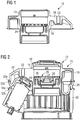
- FIG. 1 a composite component 10 according to a first embodiment is shown in longitudinal section, which is shown in FIG Fig. 2 illustrated air spring component 12 is used according to a first embodiment.
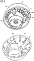
- the air spring component 12 is designed as an air spring cup 13 for an air spring of an air spring strut of a motor vehicle.
- the composite component 10 which is also referred to as a hybrid component, has a first element 14 made of a first material and a second element 16 made of a second material.
- the first element 14 is designed as a flange 18 for attachment to a motor vehicle part (not shown) and is made from a metal, in particular die-cast aluminum. Furthermore, the first element 14 has a fastening section 23 for fastening to a motor vehicle part (not shown) and a receiving section 24 for receiving an in Fig. 2 illustrated insert 26.
- the second element 18 is designed as a coating 20 which surrounds the first element 14 in areas.
- the second element 18 is made of a thermoplastic material, such as PA 66 GF 30, for example.
- the coating 20 is firmly connected to the flange 18.
- the flange 18 is inserted into an injection mold (not shown) and encapsulated with a thermoplastic material.
- the coating 20 ensures sufficient tightness of the flange 18, so that the composite component 10 is suitable for an air spring application.
- the second element 18 has a joining area 22a for connecting to a second component.
- the joining region 22a is formed during the overmolding of the first element 14 with the second element 16 and can be flat or three-dimensional.
- the illustrated air spring component 12 has the composite component 10, a middle part 28 and a lower part 30, which are connected to one another in a materially bonded manner to form the air spring cup 13.
- the middle part 28 and the lower part 30 are made of a plastic, in particular a thermoplastic plastic, such as PA 66 GF 30, for example.
- the middle part 28 has a second joining region 22b corresponding to the joining region 22a of the second element 16.
- the middle part 28 has a further joining area 32a, which is connected to a corresponding joining area 32b of the lower part 30.
- the integral connection of the parts 10, 28, 30 to the air spring component 12 takes place via the joining areas 22a, 22b, 32a, 32b.
- the parts 10, 28, 30 can be connected to one another by means of hot gas welding by the joining areas 22a, 22b, 32a, 32b are heated and / or melted or plasticized and then pressed together. After the joining areas 22a, 22b, 32a, 32b have solidified, the parts 10, 28, 30 are materially connected to one another with the formation of a weld seam (not shown). During hot gas welding, the joining areas 22a, 22b, 32a, 32b are heated and / or melted or plasticized by means of a hot gas, nitrogen being preferably used as the working gas.
- the Insert 26 is pressed into the receiving section 24.
- the receiving section 24 is provided with the coating 20.
- the Insert 26 has a guide element 34 for guiding a damper rod (not shown), a flange element 36 for pressing into the receiving section 24 and a membrane 32 connecting the guide element 34 and the flange element 36 to one another.
- a second embodiment of a first element 14 formed as a flange 18 made of a die-cast aluminum is shown, which is in the in Fig. 4 composite component 10 shown is used according to a second embodiment.
- the second embodiment of the composite component 10 differs from the first embodiment in the configuration of the second element 16.
- the second element 16 is designed as an upper part 40 for an air spring cup 13 and is connected to the flange 18 in a materially bonded manner.
- the flange 18 is inserted into an injection mold (not shown) and encapsulated with a plastic to form the upper part 40.
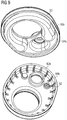
- Fig. 5 is an air spring component 12 according to a second embodiment with the in Fig. 4
- Composite component 10 shown as well as a lower part 42 are shown.
- the composite component 10 and the lower part 42 are materially connected to one another.
- the composite component 10 has a first joining area 44a and the lower part 42 has a second joining area 44b corresponding thereto.
- Both joining areas 44a, 44b are formed from an edge section 46a, 46b and a circular section 48a, 48b.
- the joining areas 44a, 44b can be materially connected to one another by means of hot gas welding.
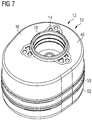
- FIG. 7 a third embodiment of an air spring component 12 designed as an air spring cup 13 is shown.
- the air spring component 12 comprises the in Fig. 4
- the composite component 10 shown has a middle part 50 and a lower part 52 which are connected to one another in a materially bonded manner.
- the composite component 10 has a joining area 54a and the central part 68 has a corresponding joining area 54b, each of which is formed from an edge section 56a, 56b, a circular section 58a, 58b and projections 60a, 60b.
- the central part 50 has a further joining region 62a and the lower part 52 has a joining region 62b corresponding thereto, which are formed from edge sections 64a, 64b.
- Fig. 10 shows an enlarged detail of a longitudinal section through a first embodiment of the joining areas 22a, 22b, 32a, 32b, 44a, 44b, 54a, 54b, 62a, 62b in the area of the edge sections 46a, 46b, 56a, 56b.
- the joining areas 22a, 22b, 32a, 32b, 44a, 44b, 54a, 54b, 62a, 62b each have a fusible projection 66 (left illustration in FIG Fig. 10 ).
- a weld seam cover 68 protrudes from one of the joining areas 22a, 22b, 32a, 32b, 44a, 44b, 54a, 54b, 62a, 62b.
- the meltable projections 66 are heated and / or melted or plasticized and pressed together by hot gas, infrared, mirror heating and / or induction, in order to produce a weld seam 70 (right illustration in FIG Fig. 10 ).
- the weld seam cover 68 makes contact with the other part and thereby covers a joint gap 72. As a result, no melt can escape, so that a clean outer surface is created.
- Fig. 11 an enlarged detail of a longitudinal section according to a second embodiment of the joining areas 22a, 22b, 32a, 32b, 44a, 44b, 54a, 54b, 62a, 62b is shown, which differs from the first embodiment in that the weld seam cover 68 is a tapering top lip 74 is formed (left representation of the Fig. 11 ), which, after being compressed, engages in a bevel 76 of the second part in order to cover the joint gap 72. This creates a smooth surface on the outside.
- the composite component 10 is distinguished by its combination of a flange 18 made of die-cast aluminum and a second element 16 made of a thermoplastic material which surrounds the flange 18 at least in some areas.
- the flange 18 is used to connect and transmit power to a motor vehicle part, and the second element 18 ensures sufficient tightness of the flange 18 made of die-cast aluminum.
- This allows the composite component 10 to be used in an air spring component, such as in an air spring cup 13 of an air spring strut.
- the second element 18 has joining geometries for the material connection of the composite component 10 with further components 28, 30, 42, 50, 52 to form an air spring cup 13.
Landscapes
- Engineering & Computer Science (AREA)
- Mechanical Engineering (AREA)
- General Engineering & Computer Science (AREA)
- Vehicle Body Suspensions (AREA)
- Lining Or Joining Of Plastics Or The Like (AREA)
- Fluid-Damping Devices (AREA)
Claims (13)
- Composant composite (10) pour un composant de ressort pneumatique (12) d'un véhicule automobile sous la forme d'un pot de ressort pneumatique, avec un premier élément (14) en un premier matériau en aluminium coulé sous pression et un deuxième élément (16) en un deuxième matériau en matière thermoplastique renforcée par de la fibre de verre, le premier élément (14) étant réalisé sous la forme d'une bride (18) pour la fixation à une pièce du véhicule automobile et le deuxième élément (16) entourant au moins par zones le premier élément (14).
- Composant composite selon la revendication 1, caractérisé en ce le deuxième élément (16) est relié matériellement et/ou positivement au premier élément (14).
- Composant composite selon la revendication 1 ou 2, caractérisé en ce que le deuxième élément (16) est conçu comme un élément de revêtement (20) et/ou de fermeture (40).
- Composant composite selon l'une quelconque des revendications précédentes, caractérisé en ce que le deuxième élément (16) comprend au moins une zone de jonction (22a, 44a, 54a) pour la jonction avec un deuxième composant (28, 42, 50).
- Composant composite selon la revendication 4, caractérisé en ce que la zone de jonction (22a, 44a, 54a) présente au moins une saillie fusible (66).
- Composant composite selon la revendication 4 ou 5, caractérisé en ce que la zone de jonction (22a, 44a, 54a) est formée d'au moins une section de bord (46a, 56a), une saillie (60a), une nervure et/ou une bande.
- Composant composite selon l'une des revendications précédentes, caractérisé en ce que le premier élément (14) comprend une portion de réception (24) pour recevoir un insert (26) pour guider une tige d'amortisseur d'un amortisseur de vibrations.
- Composant composite selon l'une quelconque des revendications précédentes, caractérisé en ce que le second matériau est un matériau thermoplastique injectable.
- Composant de ressort pneumatique (12) comprenant un composant composite (10) selon l'une quelconque des revendications 1 à 8 et au moins un deuxième composant (28, 42, 50), qui sont reliés entre eux par liaison de matière.
- Composant de ressort pneumatique selon la revendication 9, caractérisé en ce que la liaison des matériaux est effectuée par chauffage et/ou fusion et pressage ultérieur des zones de jonction (22a, 22b, 44a, 44b, 54a, 54b) des composants (10, 28, 42, 50) sous une atmosphère inerte.
- Composant de ressort pneumatique selon l'une des revendications 9 ou 10, caractérisé en ce qu'au moins l'un des composants (10, 28, 42, 50) comprend un recouvrement de cordon de soudure (68) couvrant un espace de jonction (72).
- Composant de ressort pneumatique selon l'une quelconque des revendications 9 à 11, caractérisé en ce que le composant composite (10) est réalisé sous la forme d'une partie supérieure (10, 40) et est relié à une partie inférieure (30, 42, 52) par liaison de matière pour former un pot de ressort pneumatique (13).
- Composant de ressort pneumatique selon la revendication 12, caractérisé en ce qu'une partie centrale (28, 50) est disposée entre la partie supérieure (10, 40) et la partie inférieure (30, 52), laquelle partie centrale (28, 50) est reliée matériellement à la partie supérieure (10, 40) et à la partie inférieure (30, 52) pour former un pot de ressort pneumatique (13).
Applications Claiming Priority (2)
| Application Number | Priority Date | Filing Date | Title |
|---|---|---|---|
| DE102015100281.7A DE102015100281A1 (de) | 2015-01-09 | 2015-01-09 | Verbundbauteil sowie Luftfederkomponente mit einem derartigen Verbundbauteil |
| PCT/EP2015/076984 WO2016110357A1 (fr) | 2015-01-09 | 2015-11-18 | Pièce composite et élément ressort pneumatique comprenant une telle pièce composite |
Publications (2)
| Publication Number | Publication Date |
|---|---|
| EP3242806A1 EP3242806A1 (fr) | 2017-11-15 |
| EP3242806B1 true EP3242806B1 (fr) | 2021-07-21 |
Family
ID=54548201
Family Applications (1)
| Application Number | Title | Priority Date | Filing Date |
|---|---|---|---|
| EP15795205.2A Active EP3242806B1 (fr) | 2015-01-09 | 2015-11-18 | Pièce composite et élément ressort pneumatique comprenant une telle pièce composite |
Country Status (7)
| Country | Link |
|---|---|
| US (1) | US10525782B2 (fr) |
| EP (1) | EP3242806B1 (fr) |
| JP (1) | JP6483840B2 (fr) |
| KR (1) | KR102068690B1 (fr) |
| CN (1) | CN107107697B (fr) |
| DE (1) | DE102015100281A1 (fr) |
| WO (1) | WO2016110357A1 (fr) |
Families Citing this family (9)
| Publication number | Priority date | Publication date | Assignee | Title |
|---|---|---|---|---|
| DE102014212788A1 (de) * | 2014-07-02 | 2016-01-07 | Bayerische Motoren Werke Aktiengesellschaft | Luftausgleichsbehälter |
| US10752070B2 (en) * | 2015-07-01 | 2020-08-25 | Firestone Industrial Products Company, Llc | Clamping plates and gas spring assemblies as well as suspension systems and methods including same |
| DE102017216052A1 (de) | 2016-11-24 | 2018-05-24 | Continental Teves Ag & Co. Ohg | Luftfederbein mit einem Luftfederdeckel mit Bajonettverschluss |
| DE102018216989A1 (de) | 2017-10-04 | 2019-04-04 | Continental Teves Ag & Co. Ohg | Druckkörper für ein Druckluftsystem |
| WO2019068790A1 (fr) | 2017-10-04 | 2019-04-11 | Continental Teves Ag & Co. Ohg | Jambe de suspension pneumatique avec un couvercle de suspension pneumatique en matière plastique |
| CN111433486B (zh) * | 2017-12-01 | 2022-05-10 | 大陆-特韦斯贸易合伙股份公司及两合公司 | 盖中具有加强芯的空气弹簧滑柱组件 |
| DE102018216717A1 (de) | 2018-09-28 | 2020-04-02 | Continental Teves Ag & Co. Ohg | Luftfederbein mit einem Kunststoff-Luftfederdeckel aus Thermoplast |
| CN111795098B (zh) * | 2020-05-25 | 2021-11-02 | 中国第一汽车股份有限公司 | 一种空气弹簧总成 |
| DE102020134375A1 (de) * | 2020-12-21 | 2022-06-23 | Vibracoustic Se | Bauteil insbesondere für eine Luftfeder, ein Luftfederbein, einen Luftfederdämpfer oder ein Topmountgehäuse und Verfahren zum Herstellen des Bauteils |
Citations (22)
| Publication number | Priority date | Publication date | Assignee | Title |
|---|---|---|---|---|
| JP3169153B2 (ja) | 1993-12-28 | 2001-05-21 | トヨタ自動車株式会社 | プラスチック部材の接合方法 |
| DE20210955U1 (de) * | 2002-07-19 | 2002-09-19 | Gomma C F Spa | Oberes Verbindungselement für eine Luftfeder eines Kraftfahrzeugs |
| DE10216175C1 (de) | 2002-04-12 | 2003-07-24 | Stiebel Eltron Gmbh & Co Kg | Bauteil, insbesondere Behälter oder Rohr, und Verfahren zur Herstellung eines Behälters |
| EP1426648A1 (fr) | 2002-12-06 | 2004-06-09 | Continental Aktiengesellschaft | Couvercle de ressort à air comprenant un volume d'air supplémentaire et procédé de fabrication de celui-ci |
| DE10347934A1 (de) * | 2002-11-29 | 2004-06-09 | Phoenix Ag | Luftfederanordnung |
| DE102004015881A1 (de) | 2003-04-09 | 2004-12-23 | Aisan Kogyo K.K., Obu | Einlassverteiler aus Harz |
| EP1602468A2 (fr) | 2004-05-26 | 2005-12-07 | Toyota Boshoku Kabushiki Kaisya | Structure de liaison pour chambre d'égalisation de pression,chambre d'égalisation de pression et collecteur d'admission |
| DE102004061989A1 (de) | 2004-12-23 | 2006-07-06 | Continental Aktiengesellschaft | Luftfeder eines Kraftfahrzeugs |
| US20070096374A1 (en) * | 2004-06-23 | 2007-05-03 | Karsten Scholz | Air spring having a roll-off piston and a rolling-lobe flexible member having at least one attachment part vulcanized thereon |
| DE102006010815A1 (de) | 2006-03-07 | 2007-09-13 | Geiger Technik Gesellschaft mit beschränkter Haftung | Gehäuse aus thermoplastischem Kunststoff und Verfahren zu seiner Herstellung |
| DE102007026826A1 (de) | 2007-06-06 | 2008-12-11 | Mann + Hummel Gmbh | Ansaugsystem |
| DE102007035640A1 (de) | 2007-07-27 | 2009-01-29 | Lkh-Kunststoffwerk Gmbh & Co. Kg | Tauchkolben |
| JP2009127682A (ja) | 2007-11-21 | 2009-06-11 | Fukoku Co Ltd | 空気ばね |
| EP2153977A2 (fr) | 2008-08-11 | 2010-02-17 | ElringKlinger AG | Bloc doté d'éléments en matière plastique soudés ensemble et son procédé de fabrication |
| DE102008048793A1 (de) | 2008-09-24 | 2010-03-25 | Mann + Hummel Gmbh | Verfahren zur Herstellung einer Kunststoffölwanne mittels Heißgasschweißen |
| DE102009049047A1 (de) | 2008-11-13 | 2010-06-10 | MANDO CORPORATION, Pyeongtaek | Halterung zur Befestigung eines Schwingungsdämpfers |
| DE102010004204A1 (de) | 2010-01-08 | 2011-08-25 | Trelleborg Automotive Germany GmbH, 56203 | Verfahren zur Herstellung einer Nut an einem Lagergehäuse sowie gemäß dem Verfahren hergestelltes Lagergehäuse und Federbeinstützlger mit dem erfindungsgemäßen Lagergehäuse |
| JP4948004B2 (ja) | 2006-03-16 | 2012-06-06 | 東京濾器株式会社 | 樹脂製ケースと樹脂製カバーとの振動溶着構造 |
| DE102013219912A1 (de) | 2012-10-01 | 2014-04-03 | Firestone Industrial Products Company LLC | Endelement und Gasfederanordnung, welche dasselbe aufweist |
| DE102012110112A1 (de) | 2012-10-23 | 2014-04-24 | a.i.m. GmbH Werkzeugbau - Stanz + Fügetechnik | Gasfedertopf für eine Gasfeder-Stoßdämpfereinrichtung |
| DE102013212982A1 (de) * | 2012-11-22 | 2014-06-05 | Continental Teves Ag & Co. Ohg | Luftfedereinheit |
| EP2775162A2 (fr) | 2013-03-08 | 2014-09-10 | Veyance Technologies, Inc. | Plaque de talon composite et suspension pneumatique l'utilisant |
Family Cites Families (33)
| Publication number | Priority date | Publication date | Assignee | Title |
|---|---|---|---|---|
| US4104089A (en) * | 1976-07-08 | 1978-08-01 | Nippon Light Metal Company Limited | Die-cast aluminum alloy products |
| US4796870A (en) * | 1987-05-18 | 1989-01-10 | The Firestone Tire & Rubber Company | Suspension system for vehicles containing combination isolator mount and air spring closure |
| US5005808A (en) | 1987-12-01 | 1991-04-09 | The Goodyear Tire & Rubber Company | Airspring end member and airspring assembly |
| US4988082A (en) * | 1989-07-18 | 1991-01-29 | General Motors Corporation | Spliced air sleeve assembly for air spring damper |
| US5752692A (en) | 1997-01-06 | 1998-05-19 | The Gates Corporation | Side load compensating airspring strut |
| US6199837B1 (en) * | 1998-05-01 | 2001-03-13 | Bridgestone/Firestone, Inc. | Thermoplastic elastomer air spring |
| US6386524B1 (en) * | 2000-02-15 | 2002-05-14 | Bfs Diversified Products, Llc | Pedestal mounted full reservoir air spring piston |
| JP2002364469A (ja) * | 2001-06-04 | 2002-12-18 | Keihin Corp | 車両用吸気マニホールドの製造方法 |
| US6843472B2 (en) * | 2003-01-21 | 2005-01-18 | The Pullman Company | Upper shock mount isolator with integral air spring housing pivot bearing |
| DE10315679A1 (de) * | 2003-04-07 | 2004-10-21 | Bayerische Motoren Werke Ag | Luftfederbein für ein Kraftfahrzeug |
| JP2004316468A (ja) * | 2003-04-11 | 2004-11-11 | Aisan Ind Co Ltd | 樹脂製インテークマニホールド |
| DE102004060727A1 (de) | 2004-12-17 | 2006-07-06 | Vibracoustic Gmbh & Co. Kg | Luftfeder und Verfahren zur Abdichtung einer Luftfeder |
| ITMI20050211A1 (it) | 2005-02-14 | 2006-08-15 | Stuani S P A | Pistone perfezionato per molle ad aria applicabile a sospensioni di autoveicoli rimorchi semirimorchi |
| US7773172B2 (en) * | 2005-03-01 | 2010-08-10 | Northrop Grumman Corporation | Line attenuation tunable optical filter |
| JP2007111926A (ja) | 2005-10-19 | 2007-05-10 | Toyota Motor Corp | 熱可塑性樹脂部材のレーザ溶着方法およびレーザ溶着装置 |
| DE102006009301A1 (de) * | 2006-03-01 | 2007-09-06 | Daimlerchrysler Ag | Einzelradaufhängung mit fahrwerksversteifenden Gas- oder Hydraulikfederungsteilen |
| ITTO20060083U1 (it) | 2006-05-31 | 2007-12-01 | Gomma C F Spa | Pistone di una molla ad aria per un autoveicolo di tipo assemblato |
| JP2007321936A (ja) * | 2006-06-05 | 2007-12-13 | Fukoku Co Ltd | 空気ばね |
| DE102006036248A1 (de) * | 2006-08-03 | 2008-02-07 | Continental Aktiengesellschaft | Luftfeder für Fahrzeuge |
| DE102006043471A1 (de) * | 2006-09-15 | 2008-03-27 | Continental Aktiengesellschaft | Luftfederbein |
| CA2730255A1 (fr) | 2008-07-09 | 2010-01-14 | Firestone Industrial Products Company, Llc | Ressort a gaz, ensemble amortisseur a gaz et procede associe |
| KR100917557B1 (ko) * | 2008-08-19 | 2009-09-16 | 현대모비스 주식회사 | 에어 현가 장치의 에어 스프링 장치 |
| JP2010090989A (ja) | 2008-10-08 | 2010-04-22 | Bridgestone Corp | 空気ばね |
| JP5277080B2 (ja) | 2009-06-08 | 2013-08-28 | 東洋ゴム工業株式会社 | 空気ばね |
| EP2467272A1 (fr) * | 2009-08-19 | 2012-06-27 | Aktas Hava Süspansiyon Sistemleri Sanay Ve Ticaret Anonim Sirketi | Amortisseur pour suspension pneumatique |
| DE102011050103A1 (de) | 2011-05-04 | 2012-11-08 | Contitech Luftfedersysteme Gmbh | Abrollkolben für einen Luftfederrollbalg |
| BR112013029622B1 (pt) * | 2011-05-17 | 2021-08-17 | Hendrickson Usa, L.L.C | Pistão para uma suspensão pneumática de um veículo pesado |
| WO2013007527A1 (fr) * | 2011-07-11 | 2013-01-17 | Continental Teves Ag & Co. Ohg | Module de ressort pneumatique |
| DE102012015032B4 (de) | 2012-07-31 | 2022-09-29 | Man Truck & Bus Se | Abrollkolben für ein Gasfedersystem von Fahrzeugen |
| US9140327B2 (en) * | 2012-08-31 | 2015-09-22 | Firestone Industrial Products Company, Llc | End member assemblies and gas spring assemblies including same |
| DE102013106290B3 (de) * | 2013-06-17 | 2014-10-16 | Vibracoustic Cv Air Springs Gmbh | Luftfederbefestigungssystem |
| DE102013113737A1 (de) | 2013-12-10 | 2015-06-11 | Trelleborgvibracoustic Gmbh | Luftfederkomponente |
| JP5766836B1 (ja) * | 2014-03-12 | 2015-08-19 | 住友理工株式会社 | 車両用ダストカバー組付体およびその製造方法 |
-
2015
- 2015-01-09 DE DE102015100281.7A patent/DE102015100281A1/de active Pending
- 2015-11-18 US US15/541,717 patent/US10525782B2/en active Active
- 2015-11-18 EP EP15795205.2A patent/EP3242806B1/fr active Active
- 2015-11-18 JP JP2017536326A patent/JP6483840B2/ja active Active
- 2015-11-18 KR KR1020177018918A patent/KR102068690B1/ko active IP Right Grant
- 2015-11-18 CN CN201580072371.3A patent/CN107107697B/zh active Active
- 2015-11-18 WO PCT/EP2015/076984 patent/WO2016110357A1/fr active Application Filing
Patent Citations (22)
| Publication number | Priority date | Publication date | Assignee | Title |
|---|---|---|---|---|
| JP3169153B2 (ja) | 1993-12-28 | 2001-05-21 | トヨタ自動車株式会社 | プラスチック部材の接合方法 |
| DE10216175C1 (de) | 2002-04-12 | 2003-07-24 | Stiebel Eltron Gmbh & Co Kg | Bauteil, insbesondere Behälter oder Rohr, und Verfahren zur Herstellung eines Behälters |
| DE20210955U1 (de) * | 2002-07-19 | 2002-09-19 | Gomma C F Spa | Oberes Verbindungselement für eine Luftfeder eines Kraftfahrzeugs |
| DE10347934A1 (de) * | 2002-11-29 | 2004-06-09 | Phoenix Ag | Luftfederanordnung |
| EP1426648A1 (fr) | 2002-12-06 | 2004-06-09 | Continental Aktiengesellschaft | Couvercle de ressort à air comprenant un volume d'air supplémentaire et procédé de fabrication de celui-ci |
| DE102004015881A1 (de) | 2003-04-09 | 2004-12-23 | Aisan Kogyo K.K., Obu | Einlassverteiler aus Harz |
| EP1602468A2 (fr) | 2004-05-26 | 2005-12-07 | Toyota Boshoku Kabushiki Kaisya | Structure de liaison pour chambre d'égalisation de pression,chambre d'égalisation de pression et collecteur d'admission |
| US20070096374A1 (en) * | 2004-06-23 | 2007-05-03 | Karsten Scholz | Air spring having a roll-off piston and a rolling-lobe flexible member having at least one attachment part vulcanized thereon |
| DE102004061989A1 (de) | 2004-12-23 | 2006-07-06 | Continental Aktiengesellschaft | Luftfeder eines Kraftfahrzeugs |
| DE102006010815A1 (de) | 2006-03-07 | 2007-09-13 | Geiger Technik Gesellschaft mit beschränkter Haftung | Gehäuse aus thermoplastischem Kunststoff und Verfahren zu seiner Herstellung |
| JP4948004B2 (ja) | 2006-03-16 | 2012-06-06 | 東京濾器株式会社 | 樹脂製ケースと樹脂製カバーとの振動溶着構造 |
| DE102007026826A1 (de) | 2007-06-06 | 2008-12-11 | Mann + Hummel Gmbh | Ansaugsystem |
| DE102007035640A1 (de) | 2007-07-27 | 2009-01-29 | Lkh-Kunststoffwerk Gmbh & Co. Kg | Tauchkolben |
| JP2009127682A (ja) | 2007-11-21 | 2009-06-11 | Fukoku Co Ltd | 空気ばね |
| EP2153977A2 (fr) | 2008-08-11 | 2010-02-17 | ElringKlinger AG | Bloc doté d'éléments en matière plastique soudés ensemble et son procédé de fabrication |
| DE102008048793A1 (de) | 2008-09-24 | 2010-03-25 | Mann + Hummel Gmbh | Verfahren zur Herstellung einer Kunststoffölwanne mittels Heißgasschweißen |
| DE102009049047A1 (de) | 2008-11-13 | 2010-06-10 | MANDO CORPORATION, Pyeongtaek | Halterung zur Befestigung eines Schwingungsdämpfers |
| DE102010004204A1 (de) | 2010-01-08 | 2011-08-25 | Trelleborg Automotive Germany GmbH, 56203 | Verfahren zur Herstellung einer Nut an einem Lagergehäuse sowie gemäß dem Verfahren hergestelltes Lagergehäuse und Federbeinstützlger mit dem erfindungsgemäßen Lagergehäuse |
| DE102013219912A1 (de) | 2012-10-01 | 2014-04-03 | Firestone Industrial Products Company LLC | Endelement und Gasfederanordnung, welche dasselbe aufweist |
| DE102012110112A1 (de) | 2012-10-23 | 2014-04-24 | a.i.m. GmbH Werkzeugbau - Stanz + Fügetechnik | Gasfedertopf für eine Gasfeder-Stoßdämpfereinrichtung |
| DE102013212982A1 (de) * | 2012-11-22 | 2014-06-05 | Continental Teves Ag & Co. Ohg | Luftfedereinheit |
| EP2775162A2 (fr) | 2013-03-08 | 2014-09-10 | Veyance Technologies, Inc. | Plaque de talon composite et suspension pneumatique l'utilisant |
Non-Patent Citations (6)
Also Published As
| Publication number | Publication date |
|---|---|
| EP3242806A1 (fr) | 2017-11-15 |
| DE102015100281A1 (de) | 2016-07-14 |
| KR20170103807A (ko) | 2017-09-13 |
| CN107107697A (zh) | 2017-08-29 |
| JP2018504562A (ja) | 2018-02-15 |
| US10525782B2 (en) | 2020-01-07 |
| KR102068690B1 (ko) | 2020-01-21 |
| JP6483840B2 (ja) | 2019-03-13 |
| US20180015800A1 (en) | 2018-01-18 |
| WO2016110357A1 (fr) | 2016-07-14 |
| CN107107697B (zh) | 2021-03-09 |
Similar Documents
| Publication | Publication Date | Title |
|---|---|---|
| EP3242806B1 (fr) | Pièce composite et élément ressort pneumatique comprenant une telle pièce composite | |
| EP3080477B1 (fr) | Élément ressort pneumatique | |
| EP0712741B1 (fr) | Bras pour la liaison en rotation d'éléments de la suspension de véhicules à moteur | |
| DE102007014116A1 (de) | Säule als Teil einer Karosseriestruktur eines Kraftwagens | |
| DE102011080493B3 (de) | Schaltvorrichtung eines Kraftfahrzeuggetriebes | |
| EP1036680A2 (fr) | Essieu à traverse déformable en torsion pour un véhicule automobile | |
| DE102013105091A1 (de) | Kugelgelenk und Kraftfahrzeug-Lenker | |
| DE102019102493A1 (de) | Kraftfahrzeuglenker | |
| WO2019068790A1 (fr) | Jambe de suspension pneumatique avec un couvercle de suspension pneumatique en matière plastique | |
| DE4445251A1 (de) | Befestigungsanordnung zwischen einem Innenteil und einem Außenteil | |
| EP3350472B1 (fr) | Palier amortisseur muni d'un boîtier et d'un couvercle | |
| DE112015000720T5 (de) | Gasbetriebener Druckantrieb und abgedichtete Kolbenstange dafür | |
| DE102015100261B4 (de) | Träger für ein Kraftfahrzeug und Herstellungsverfahren für einen Träger für ein Kraftfahrzeug | |
| DE10335956A1 (de) | Federkonstruktion | |
| DE102012009458B4 (de) | Lager zum elastischen Koppeln zweier Bauteile | |
| EP3030804A1 (fr) | Système d'amortisseur de vibrations pour véhicule automobile | |
| DE102011000934B4 (de) | Kugelgelenk, insbesondere für ein Fahrwerk eines Kraftfahrzeuges | |
| DE102005013262A1 (de) | Verfahren zum Anbringen eines Schusskanals an eine Airbagabdeckung mit integrierter Sollbruchlinie und eine verfahrensgemäß hergestellte Baugruppe | |
| WO2019106058A1 (fr) | Jambe de ressort pneumatique comportant un noyau de renforcement dans la coupelle | |
| EP2340376B1 (fr) | Transmission a billes et son procede de fabrication | |
| DE102007018458A1 (de) | Karosseriebauteil für einen Kraftwagen und Verfahren zu dessen Herstellung | |
| WO2017129545A1 (fr) | Amortisseur de vibrations | |
| EP3822100B1 (fr) | Composant formant ressort pneumatique | |
| DE19838943C2 (de) | Befestigung eines Anlenkteils auf einem Kolben-Zylinderaggregat | |
| DE102017127788A1 (de) | Kraftfahrzeuglenker und Verfahren zur Herstellung eines Kraftfahrzeuglenkers |
Legal Events
| Date | Code | Title | Description |
|---|---|---|---|
| STAA | Information on the status of an ep patent application or granted ep patent |
Free format text: STATUS: THE INTERNATIONAL PUBLICATION HAS BEEN MADE |
|
| PUAI | Public reference made under article 153(3) epc to a published international application that has entered the european phase |
Free format text: ORIGINAL CODE: 0009012 |
|
| STAA | Information on the status of an ep patent application or granted ep patent |
Free format text: STATUS: REQUEST FOR EXAMINATION WAS MADE |
|
| 17P | Request for examination filed |
Effective date: 20170606 |
|
| AK | Designated contracting states |
Kind code of ref document: A1 Designated state(s): AL AT BE BG CH CY CZ DE DK EE ES FI FR GB GR HR HU IE IS IT LI LT LU LV MC MK MT NL NO PL PT RO RS SE SI SK SM TR |
|
| AX | Request for extension of the european patent |
Extension state: BA ME |
|
| DAV | Request for validation of the european patent (deleted) | ||
| DAX | Request for extension of the european patent (deleted) | ||
| RIC1 | Information provided on ipc code assigned before grant |
Ipc: B60G 15/12 20060101AFI20200330BHEP Ipc: B60G 11/28 20060101ALI20200330BHEP Ipc: F16F 9/54 20060101ALI20200330BHEP Ipc: F16F 9/05 20060101ALI20200330BHEP |
|
| STAA | Information on the status of an ep patent application or granted ep patent |
Free format text: STATUS: EXAMINATION IS IN PROGRESS |
|
| 17Q | First examination report despatched |
Effective date: 20200722 |
|
| STAA | Information on the status of an ep patent application or granted ep patent |
Free format text: STATUS: EXAMINATION IS IN PROGRESS |
|
| GRAP | Despatch of communication of intention to grant a patent |
Free format text: ORIGINAL CODE: EPIDOSNIGR1 |
|
| STAA | Information on the status of an ep patent application or granted ep patent |
Free format text: STATUS: GRANT OF PATENT IS INTENDED |
|
| INTG | Intention to grant announced |
Effective date: 20210408 |
|
| GRAS | Grant fee paid |
Free format text: ORIGINAL CODE: EPIDOSNIGR3 |
|
| GRAA | (expected) grant |
Free format text: ORIGINAL CODE: 0009210 |
|
| STAA | Information on the status of an ep patent application or granted ep patent |
Free format text: STATUS: THE PATENT HAS BEEN GRANTED |
|
| RAP3 | Party data changed (applicant data changed or rights of an application transferred) |
Owner name: VIBRACOUSTIC SE |
|
| AK | Designated contracting states |
Kind code of ref document: B1 Designated state(s): AL AT BE BG CH CY CZ DE DK EE ES FI FR GB GR HR HU IE IS IT LI LT LU LV MC MK MT NL NO PL PT RO RS SE SI SK SM TR |
|
| REG | Reference to a national code |
Ref country code: GB Ref legal event code: FG4D Free format text: NOT ENGLISH |
|
| REG | Reference to a national code |
Ref country code: CH Ref legal event code: EP |
|
| REG | Reference to a national code |
Ref country code: DE Ref legal event code: R096 Ref document number: 502015014969 Country of ref document: DE |
|
| REG | Reference to a national code |
Ref country code: AT Ref legal event code: REF Ref document number: 1412271 Country of ref document: AT Kind code of ref document: T Effective date: 20210815 |
|
| REG | Reference to a national code |
Ref country code: IE Ref legal event code: FG4D Free format text: LANGUAGE OF EP DOCUMENT: GERMAN |
|
| REG | Reference to a national code |
Ref country code: LT Ref legal event code: MG9D |
|
| REG | Reference to a national code |
Ref country code: NL Ref legal event code: MP Effective date: 20210721 |
|
| PG25 | Lapsed in a contracting state [announced via postgrant information from national office to epo] |
Ref country code: LT Free format text: LAPSE BECAUSE OF FAILURE TO SUBMIT A TRANSLATION OF THE DESCRIPTION OR TO PAY THE FEE WITHIN THE PRESCRIBED TIME-LIMIT Effective date: 20210721 Ref country code: BG Free format text: LAPSE BECAUSE OF FAILURE TO SUBMIT A TRANSLATION OF THE DESCRIPTION OR TO PAY THE FEE WITHIN THE PRESCRIBED TIME-LIMIT Effective date: 20211021 Ref country code: PT Free format text: LAPSE BECAUSE OF FAILURE TO SUBMIT A TRANSLATION OF THE DESCRIPTION OR TO PAY THE FEE WITHIN THE PRESCRIBED TIME-LIMIT Effective date: 20211122 Ref country code: NO Free format text: LAPSE BECAUSE OF FAILURE TO SUBMIT A TRANSLATION OF THE DESCRIPTION OR TO PAY THE FEE WITHIN THE PRESCRIBED TIME-LIMIT Effective date: 20211021 Ref country code: NL Free format text: LAPSE BECAUSE OF FAILURE TO SUBMIT A TRANSLATION OF THE DESCRIPTION OR TO PAY THE FEE WITHIN THE PRESCRIBED TIME-LIMIT Effective date: 20210721 Ref country code: ES Free format text: LAPSE BECAUSE OF FAILURE TO SUBMIT A TRANSLATION OF THE DESCRIPTION OR TO PAY THE FEE WITHIN THE PRESCRIBED TIME-LIMIT Effective date: 20210721 Ref country code: FI Free format text: LAPSE BECAUSE OF FAILURE TO SUBMIT A TRANSLATION OF THE DESCRIPTION OR TO PAY THE FEE WITHIN THE PRESCRIBED TIME-LIMIT Effective date: 20210721 Ref country code: SE Free format text: LAPSE BECAUSE OF FAILURE TO SUBMIT A TRANSLATION OF THE DESCRIPTION OR TO PAY THE FEE WITHIN THE PRESCRIBED TIME-LIMIT Effective date: 20210721 Ref country code: RS Free format text: LAPSE BECAUSE OF FAILURE TO SUBMIT A TRANSLATION OF THE DESCRIPTION OR TO PAY THE FEE WITHIN THE PRESCRIBED TIME-LIMIT Effective date: 20210721 Ref country code: HR Free format text: LAPSE BECAUSE OF FAILURE TO SUBMIT A TRANSLATION OF THE DESCRIPTION OR TO PAY THE FEE WITHIN THE PRESCRIBED TIME-LIMIT Effective date: 20210721 |
|
| PG25 | Lapsed in a contracting state [announced via postgrant information from national office to epo] |
Ref country code: PL Free format text: LAPSE BECAUSE OF FAILURE TO SUBMIT A TRANSLATION OF THE DESCRIPTION OR TO PAY THE FEE WITHIN THE PRESCRIBED TIME-LIMIT Effective date: 20210721 Ref country code: LV Free format text: LAPSE BECAUSE OF FAILURE TO SUBMIT A TRANSLATION OF THE DESCRIPTION OR TO PAY THE FEE WITHIN THE PRESCRIBED TIME-LIMIT Effective date: 20210721 Ref country code: GR Free format text: LAPSE BECAUSE OF FAILURE TO SUBMIT A TRANSLATION OF THE DESCRIPTION OR TO PAY THE FEE WITHIN THE PRESCRIBED TIME-LIMIT Effective date: 20211022 |
|
| REG | Reference to a national code |
Ref country code: DE Ref legal event code: R026 Ref document number: 502015014969 Country of ref document: DE |
|
| PLBI | Opposition filed |
Free format text: ORIGINAL CODE: 0009260 |
|
| PG25 | Lapsed in a contracting state [announced via postgrant information from national office to epo] |
Ref country code: DK Free format text: LAPSE BECAUSE OF FAILURE TO SUBMIT A TRANSLATION OF THE DESCRIPTION OR TO PAY THE FEE WITHIN THE PRESCRIBED TIME-LIMIT Effective date: 20210721 |
|
| PLAX | Notice of opposition and request to file observation + time limit sent |
Free format text: ORIGINAL CODE: EPIDOSNOBS2 |
|
| 26 | Opposition filed |
Opponent name: CONTINENTAL TEVES AG & CO. OHG Effective date: 20220414 |
|
| PG25 | Lapsed in a contracting state [announced via postgrant information from national office to epo] |
Ref country code: SM Free format text: LAPSE BECAUSE OF FAILURE TO SUBMIT A TRANSLATION OF THE DESCRIPTION OR TO PAY THE FEE WITHIN THE PRESCRIBED TIME-LIMIT Effective date: 20210721 Ref country code: SK Free format text: LAPSE BECAUSE OF FAILURE TO SUBMIT A TRANSLATION OF THE DESCRIPTION OR TO PAY THE FEE WITHIN THE PRESCRIBED TIME-LIMIT Effective date: 20210721 Ref country code: RO Free format text: LAPSE BECAUSE OF FAILURE TO SUBMIT A TRANSLATION OF THE DESCRIPTION OR TO PAY THE FEE WITHIN THE PRESCRIBED TIME-LIMIT Effective date: 20210721 Ref country code: EE Free format text: LAPSE BECAUSE OF FAILURE TO SUBMIT A TRANSLATION OF THE DESCRIPTION OR TO PAY THE FEE WITHIN THE PRESCRIBED TIME-LIMIT Effective date: 20210721 Ref country code: CZ Free format text: LAPSE BECAUSE OF FAILURE TO SUBMIT A TRANSLATION OF THE DESCRIPTION OR TO PAY THE FEE WITHIN THE PRESCRIBED TIME-LIMIT Effective date: 20210721 Ref country code: AL Free format text: LAPSE BECAUSE OF FAILURE TO SUBMIT A TRANSLATION OF THE DESCRIPTION OR TO PAY THE FEE WITHIN THE PRESCRIBED TIME-LIMIT Effective date: 20210721 |
|
| PG25 | Lapsed in a contracting state [announced via postgrant information from national office to epo] |
Ref country code: MC Free format text: LAPSE BECAUSE OF FAILURE TO SUBMIT A TRANSLATION OF THE DESCRIPTION OR TO PAY THE FEE WITHIN THE PRESCRIBED TIME-LIMIT Effective date: 20210721 |
|
| REG | Reference to a national code |
Ref country code: CH Ref legal event code: PL |
|
| PG25 | Lapsed in a contracting state [announced via postgrant information from national office to epo] |
Ref country code: LU Free format text: LAPSE BECAUSE OF NON-PAYMENT OF DUE FEES Effective date: 20211118 Ref country code: IT Free format text: LAPSE BECAUSE OF FAILURE TO SUBMIT A TRANSLATION OF THE DESCRIPTION OR TO PAY THE FEE WITHIN THE PRESCRIBED TIME-LIMIT Effective date: 20210721 Ref country code: BE Free format text: LAPSE BECAUSE OF NON-PAYMENT OF DUE FEES Effective date: 20211130 |
|
| REG | Reference to a national code |
Ref country code: BE Ref legal event code: MM Effective date: 20211130 |
|
| PLAB | Opposition data, opponent's data or that of the opponent's representative modified |
Free format text: ORIGINAL CODE: 0009299OPPO |
|
| PLBB | Reply of patent proprietor to notice(s) of opposition received |
Free format text: ORIGINAL CODE: EPIDOSNOBS3 |
|
| R26 | Opposition filed (corrected) |
Opponent name: CONTINENTAL AUTOMOTIVE TECHNOLOGIES GMBH Effective date: 20220414 |
|
| PG25 | Lapsed in a contracting state [announced via postgrant information from national office to epo] |
Ref country code: IE Free format text: LAPSE BECAUSE OF NON-PAYMENT OF DUE FEES Effective date: 20211118 |
|
| REG | Reference to a national code |
Ref country code: AT Ref legal event code: MM01 Ref document number: 1412271 Country of ref document: AT Kind code of ref document: T Effective date: 20211118 |
|
| PG25 | Lapsed in a contracting state [announced via postgrant information from national office to epo] |
Ref country code: AT Free format text: LAPSE BECAUSE OF NON-PAYMENT OF DUE FEES Effective date: 20211118 |
|
| PG25 | Lapsed in a contracting state [announced via postgrant information from national office to epo] |
Ref country code: HU Free format text: LAPSE BECAUSE OF FAILURE TO SUBMIT A TRANSLATION OF THE DESCRIPTION OR TO PAY THE FEE WITHIN THE PRESCRIBED TIME-LIMIT; INVALID AB INITIO Effective date: 20151118 |
|
| PG25 | Lapsed in a contracting state [announced via postgrant information from national office to epo] |
Ref country code: CY Free format text: LAPSE BECAUSE OF FAILURE TO SUBMIT A TRANSLATION OF THE DESCRIPTION OR TO PAY THE FEE WITHIN THE PRESCRIBED TIME-LIMIT Effective date: 20210721 |
|
| PG25 | Lapsed in a contracting state [announced via postgrant information from national office to epo] |
Ref country code: LI Free format text: LAPSE BECAUSE OF NON-PAYMENT OF DUE FEES Effective date: 20220630 Ref country code: CH Free format text: LAPSE BECAUSE OF NON-PAYMENT OF DUE FEES Effective date: 20220630 |
|
| P01 | Opt-out of the competence of the unified patent court (upc) registered |
Effective date: 20230627 |
|
| PGFP | Annual fee paid to national office [announced via postgrant information from national office to epo] |
Ref country code: GB Payment date: 20231130 Year of fee payment: 9 |
|
| PGFP | Annual fee paid to national office [announced via postgrant information from national office to epo] |
Ref country code: FR Payment date: 20231127 Year of fee payment: 9 Ref country code: DE Payment date: 20231130 Year of fee payment: 9 |
|
| PG25 | Lapsed in a contracting state [announced via postgrant information from national office to epo] |
Ref country code: MK Free format text: LAPSE BECAUSE OF FAILURE TO SUBMIT A TRANSLATION OF THE DESCRIPTION OR TO PAY THE FEE WITHIN THE PRESCRIBED TIME-LIMIT Effective date: 20210721 |