EP3242806B1 - Verbundbauteil sowie luftfederkomponente mit einem derartigen verbundbauteil - Google Patents
Verbundbauteil sowie luftfederkomponente mit einem derartigen verbundbauteil Download PDFInfo
- Publication number
- EP3242806B1 EP3242806B1 EP15795205.2A EP15795205A EP3242806B1 EP 3242806 B1 EP3242806 B1 EP 3242806B1 EP 15795205 A EP15795205 A EP 15795205A EP 3242806 B1 EP3242806 B1 EP 3242806B1
- Authority
- EP
- European Patent Office
- Prior art keywords
- air spring
- composite component
- component according
- component
- joining
- Prior art date
- Legal status (The legal status is an assumption and is not a legal conclusion. Google has not performed a legal analysis and makes no representation as to the accuracy of the status listed.)
- Active
Links
Images


Classifications
-
- B—PERFORMING OPERATIONS; TRANSPORTING
- B60—VEHICLES IN GENERAL
- B60G—VEHICLE SUSPENSION ARRANGEMENTS
- B60G11/00—Resilient suspensions characterised by arrangement, location or kind of springs
- B60G11/26—Resilient suspensions characterised by arrangement, location or kind of springs having fluid springs only, e.g. hydropneumatic springs
- B60G11/28—Resilient suspensions characterised by arrangement, location or kind of springs having fluid springs only, e.g. hydropneumatic springs characterised by means specially adapted for attaching the spring to axle or sprung part of the vehicle
-
- B—PERFORMING OPERATIONS; TRANSPORTING
- B60—VEHICLES IN GENERAL
- B60G—VEHICLE SUSPENSION ARRANGEMENTS
- B60G15/00—Resilient suspensions characterised by arrangement, location or type of combined spring and vibration damper, e.g. telescopic type
- B60G15/08—Resilient suspensions characterised by arrangement, location or type of combined spring and vibration damper, e.g. telescopic type having fluid spring
- B60G15/12—Resilient suspensions characterised by arrangement, location or type of combined spring and vibration damper, e.g. telescopic type having fluid spring and fluid damper
-
- F—MECHANICAL ENGINEERING; LIGHTING; HEATING; WEAPONS; BLASTING
- F16—ENGINEERING ELEMENTS AND UNITS; GENERAL MEASURES FOR PRODUCING AND MAINTAINING EFFECTIVE FUNCTIONING OF MACHINES OR INSTALLATIONS; THERMAL INSULATION IN GENERAL
- F16F—SPRINGS; SHOCK-ABSORBERS; MEANS FOR DAMPING VIBRATION
- F16F9/00—Springs, vibration-dampers, shock-absorbers, or similarly-constructed movement-dampers using a fluid or the equivalent as damping medium
- F16F9/02—Springs, vibration-dampers, shock-absorbers, or similarly-constructed movement-dampers using a fluid or the equivalent as damping medium using gas only or vacuum
- F16F9/04—Springs, vibration-dampers, shock-absorbers, or similarly-constructed movement-dampers using a fluid or the equivalent as damping medium using gas only or vacuum in a chamber with a flexible wall
- F16F9/05—Springs, vibration-dampers, shock-absorbers, or similarly-constructed movement-dampers using a fluid or the equivalent as damping medium using gas only or vacuum in a chamber with a flexible wall the flexible wall being of the rolling diaphragm type
- F16F9/057—Springs, vibration-dampers, shock-absorbers, or similarly-constructed movement-dampers using a fluid or the equivalent as damping medium using gas only or vacuum in a chamber with a flexible wall the flexible wall being of the rolling diaphragm type characterised by the piston
-
- F—MECHANICAL ENGINEERING; LIGHTING; HEATING; WEAPONS; BLASTING
- F16—ENGINEERING ELEMENTS AND UNITS; GENERAL MEASURES FOR PRODUCING AND MAINTAINING EFFECTIVE FUNCTIONING OF MACHINES OR INSTALLATIONS; THERMAL INSULATION IN GENERAL
- F16F—SPRINGS; SHOCK-ABSORBERS; MEANS FOR DAMPING VIBRATION
- F16F9/00—Springs, vibration-dampers, shock-absorbers, or similarly-constructed movement-dampers using a fluid or the equivalent as damping medium
- F16F9/32—Details
- F16F9/54—Arrangements for attachment
-
- B—PERFORMING OPERATIONS; TRANSPORTING
- B60—VEHICLES IN GENERAL
- B60G—VEHICLE SUSPENSION ARRANGEMENTS
- B60G2204/00—Indexing codes related to suspensions per se or to auxiliary parts
- B60G2204/10—Mounting of suspension elements
- B60G2204/12—Mounting of springs or dampers
- B60G2204/126—Mounting of pneumatic springs
-
- B—PERFORMING OPERATIONS; TRANSPORTING
- B60—VEHICLES IN GENERAL
- B60G—VEHICLE SUSPENSION ARRANGEMENTS
- B60G2206/00—Indexing codes related to the manufacturing of suspensions: constructional features, the materials used, procedures or tools
- B60G2206/01—Constructional features of suspension elements, e.g. arms, dampers, springs
- B60G2206/40—Constructional features of dampers and/or springs
- B60G2206/42—Springs
- B60G2206/424—Plunger or top retainer construction for bellows or rolling lobe type air springs
-
- B—PERFORMING OPERATIONS; TRANSPORTING
- B60—VEHICLES IN GENERAL
- B60G—VEHICLE SUSPENSION ARRANGEMENTS
- B60G2206/00—Indexing codes related to the manufacturing of suspensions: constructional features, the materials used, procedures or tools
- B60G2206/01—Constructional features of suspension elements, e.g. arms, dampers, springs
- B60G2206/70—Materials used in suspensions
- B60G2206/71—Light weight materials
- B60G2206/7102—Aluminium alloys
-
- B—PERFORMING OPERATIONS; TRANSPORTING
- B60—VEHICLES IN GENERAL
- B60G—VEHICLE SUSPENSION ARRANGEMENTS
- B60G2206/00—Indexing codes related to the manufacturing of suspensions: constructional features, the materials used, procedures or tools
- B60G2206/01—Constructional features of suspension elements, e.g. arms, dampers, springs
- B60G2206/70—Materials used in suspensions
- B60G2206/71—Light weight materials
- B60G2206/7104—Thermoplastics
-
- B—PERFORMING OPERATIONS; TRANSPORTING
- B60—VEHICLES IN GENERAL
- B60G—VEHICLE SUSPENSION ARRANGEMENTS
- B60G2206/00—Indexing codes related to the manufacturing of suspensions: constructional features, the materials used, procedures or tools
- B60G2206/01—Constructional features of suspension elements, e.g. arms, dampers, springs
- B60G2206/80—Manufacturing procedures
- B60G2206/81—Shaping
- B60G2206/8101—Shaping by casting
- B60G2206/81012—Shaping by casting by injection moulding
Definitions
- the present invention relates to a composite component for an air spring component of a motor vehicle, in particular for an air spring cup of an air spring strut of a motor vehicle.
- the invention also relates to an air spring component with such a composite component.
- Air springs are used to cushion two mutually movable vehicle parts, but also to change the level bearings of a vehicle.
- Air springs have an air-filled air spring bellows made of rubber, which is hermetically sealed by an upper closing element and a rolling piston.
- the closing element and the rolling piston are also referred to as air spring components.
- the air spring is connected to a motor vehicle part, such as the vehicle body and / or the chassis, via the air spring components.
- the air spring component can be formed from several parts that are connected to one another.
- Air springs are also used in combination with a vibration damper in air suspension struts.
- the air spring takes over the suspension function and the vibration damper takes over the damping function.
- Telescopic dampers are mostly used as vibration dampers, which have a cylinder filled with oil, with a piston rod moving into the cylinder and being dampened by the oil.
- the air spring is arranged at the end of the vibration damper and connected to the piston rod.
- the upper end element of the air spring is included designed as an air spring cup, which has a connection device for connecting a compressor. The connection to a vehicle part takes place via the air suspension cup.
- Air spring components and their constituent parts must therefore have sufficient strength for power transmission and at the same time sufficient tightness.
- WO 01/61207 A1 shows an air spring with a rolling piston which has a hollow receiving opening on an underside into which a bolt or a screw can be received or screwed
- DE 10 2007 035 640 A1 discloses a rolling piston with a lower part, on the bottom of which a fastening receptacle is formed centrally, it being possible for a nut to be inserted into the fastening receptacle.
- US 2012/0291626 A1 discloses a rolling piston with a central opening in FIG which a fastening element is integrally introduced to the rolling piston to be attached to the motor vehicle part.
- the air spring includes an upper connector.
- the connecting element has a flat metal disc.
- the connecting element comprises a plate made of plastic, for example made of glass fiber reinforced nylon, which surrounds the disk.
- DE 10 2013 212982 A1 relates to an air spring cover that is designed as a composite component. It comprises an upper part fastened to the vehicle body and at least one lower part to which an air spring bellows is fastened in an airtight manner.
- the upper part can be an aluminum casting and the lower part is formed from steel.
- the invention is based on the object of creating a composite component for an air spring component and an air spring component which have both improved strength for the transmission of force and, at the same time, improved tightness.
- the composite component for an air spring component of a motor vehicle designed as an air spring cup, in particular for an air spring cup of an air spring strut of a motor vehicle, has a first element made of a first material made of die-cast aluminum and a second element made of a second material made of glass fiber reinforced thermoplastic, the first element being a flange is designed for attachment to a motor vehicle part, and wherein the second element at least partially surrounds the first element.
- the first element made of a first material has sufficient strength and thus serves to connect and transmit power to a vehicle part, such as the vehicle body or the chassis.
- the second element made of a second material and at least partially surrounding the first element ensures sufficient tightness, in particular gas tightness, of the composite component, so that the composite component is suitable for air spring applications.
- the force is transmitted to a motor vehicle part via the flange.
- the composite component can also be referred to as a hybrid component.
- the composite component can preferably be connected to further components to form an air spring component, in particular an air spring cup.
- the first element can be formed in one piece or in several pieces.
- the first material is die-cast aluminum.
- a flange formed from die-cast aluminum has sufficient strength for power transmission.
- the first element can be a deep-drawn part or a turned part.
- the second material is also a thermoplastic, glass fiber-reinforced plastic, in particular an injectable thermoplastic.
- the thermoplastic plastic ensures that a first element made of metal, in particular die-cast aluminum, is adequately sealed.
- the preferred thermoplastic material is PA 66 GF 30.
- the second element is cohesively and / or positively connected to the first element.
- the second element is preferably connected to the first element by partially and / or completely encapsulating the first element with the second element.
- the first element can be inserted into an injection mold and the second element can be overmolded in areas and / or completely, so that the second element is firmly connected to the first element.
- the second element can be produced as a separate component and connected to the first element by a force fit, form fit and / or material fit. The second element can thus be pressed onto the first element and / or welded to the first element.
- the second element is also advantageously designed as a coating and / or closure element.
- a second element designed as a coating is mostly applied to the first element or connected to it by means of injection molding.
- a second element designed as a coating can also be applied to the first element as a paint.
- a second element designed as a closure element is preferably manufactured using the injection molding process by placing the first element in an injection mold and overmolding it with the second element, the second element forming the closure element. The second element takes on the function of a cover element to close off an air spring cup.
- the second element can have at least one joining area for connecting to a second component.
- a second component such as a lower part, a central part and / or intermediate part for forming an air spring component, in particular an air spring cup, is connected to the composite component via the joining area.
- the composite component is advantageously cohesively connected to the second component.
- the composite component is also advantageously welded to the second component. The welding is advantageously carried out under an inert atmosphere. For this purpose, the joining areas of the composite component and the second component are first heated in an inert atmosphere and then pressed.
- the joining area has at least one meltable projection.
- the joining areas can be produced directly during the overmolding of the first element with the second element. Furthermore, the joining areas can be flat, but also have a three-dimensional configuration.
- the fusible projections can either be heated and / or plasticized or melted by hot gas, infrared, mirror heating and / or induction, which then form a weld seam by pressing and solidifying with a further heated and / or plasticized joint area.
- the joining area is advantageously formed from at least one edge section, projection, rib and / or web of the second element and / or first element.
- the joining area is preferably formed from several edge sections, projections, ribs and / or webs.
- the ribs and / or webs ensure sufficient stability and rigidity of the composite component.
- the ribs and / or webs also advantageously protrude radially inwards and / or outwards from a housing wall. This means that the component can be designed in such a way that the joining area or the connection point is arranged both on the outer circumference and on the inner circumference of the component.
- the webs and / or ribs can have an approximately T-shaped basic shape. This allows the surface of the joining areas to be enlarged.
- the first element also advantageously has a receiving section for receiving an insert for guiding a damper rod of a vibration damper.
- the insert advantageously comprises a flange which can be pressed into the receiving section, a guide element for guiding the damper rod and a membrane connecting the flange and the guide section to one another.
- the second element for sealing is advantageously arranged in the region of the receiving section.
- the second element is also advantageously arranged between the first element and the insert pressed into the receiving section.
- the invention also relates to an air spring component with such a composite component and at least one second component, which are connected to one another in a materially bonded manner.
- an air spring component in particular an air spring cup for an air spring of an air spring strut of a motor vehicle, is created which has sufficient tightness and at the same time sufficient strength for power transmission to a vehicle part.
- An air spring strut preferably has an air spring and a vibration damper. The air spring takes over the suspension function and the vibration damper takes over the damping function.
- Telescopic dampers are mostly used as vibration dampers, which have a cylinder filled with oil, with a piston rod moving into the cylinder and being dampened by the oil.
- the air spring is arranged at the end of the vibration damper and connected to the piston rod. The connection to a vehicle part takes place via the air spring, in particular the air spring cup.
- the material bond takes place by heating and / or melting and subsequent pressing of joining areas of the components under an inert atmosphere.
- the cohesive connection of the two components under an inert atmosphere makes it possible to produce a pressure-bearing air spring component consisting of several components, which has sufficient tightness, strength and temperature and aging resistance in the area of the connection points or joining areas. Furthermore, the cohesive connection under an inert atmosphere ensures great design freedom of the joining areas or the connection points. Furthermore, the cohesive connection under an inert atmosphere ensures great design freedom of the joining areas or the connection points.
- the joining areas can be arranged both on the outer circumference, in particular on the edge sections of the component, and in the interior of the component.
- the joining areas can be flat, but can also have a three-dimensional configuration.
- the inert atmosphere protects against contamination of the Joining areas, since oxidation and / or reaction of the areas to be joined is prevented. As a result, the weld seam has a high level of strength and tightness.
- the heating takes place by means of hot gas, infrared, mirror heating and / or induction.
- the heating is advantageously carried out either under vacuum or using an inert working gas, in particular nitrogen, in a suitable housing.
- At least one of the components has a weld seam cover that covers a joint gap.
- the weld seam cover also advantageously protrudes from the composite component and / or the second component and is located in a corresponding recess in the composite component and / or the second component.
- the weld seam cover is advantageously designed as a circumferential folding top lip.
- the top lip protrudes from one of the components, preferably from its housing wall. When the two components are pressed together, the top lip makes contact with the other component or its housing wall, thereby covering a joint gap. The top lip thus prevents the plasticized or melted joint areas from escaping during the pressing process. As a result, it is no longer necessary to rework the weld seam in a costly manner, since a clean outer surface of the air spring component is created.
- the weld seam cover is also advantageously designed as a tapering top lip which engages in a corresponding bevel on the opposite component during the pressing process. This advantageously creates a largely smooth outer surface.
- the composite component is designed as an upper part and is materially connected to a lower part to form an air spring cup. Furthermore, a middle part is advantageously arranged between the upper part and the lower part, which is materially connected to the upper part and the lower part to form an air spring cup. This enables a switchable air spring to be implemented.
- the lower part and / or the central part are advantageously made from metal or from thermoplastic material, in particular from glass fiber-reinforced thermoplastic material.
- the preferred thermoplastic material is PA66GF30.
- the components made of plastic help to reduce weight and thus save fuel.
- Aluminum which is also comparatively light in weight, is advantageously used as the metal.
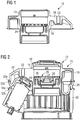
- FIG. 1 a composite component 10 according to a first embodiment is shown in longitudinal section, which is shown in FIG Fig. 2 illustrated air spring component 12 is used according to a first embodiment.
- the air spring component 12 is designed as an air spring cup 13 for an air spring of an air spring strut of a motor vehicle.
- the composite component 10 which is also referred to as a hybrid component, has a first element 14 made of a first material and a second element 16 made of a second material.
- the first element 14 is designed as a flange 18 for attachment to a motor vehicle part (not shown) and is made from a metal, in particular die-cast aluminum. Furthermore, the first element 14 has a fastening section 23 for fastening to a motor vehicle part (not shown) and a receiving section 24 for receiving an in Fig. 2 illustrated insert 26.
- the second element 18 is designed as a coating 20 which surrounds the first element 14 in areas.
- the second element 18 is made of a thermoplastic material, such as PA 66 GF 30, for example.
- the coating 20 is firmly connected to the flange 18.
- the flange 18 is inserted into an injection mold (not shown) and encapsulated with a thermoplastic material.
- the coating 20 ensures sufficient tightness of the flange 18, so that the composite component 10 is suitable for an air spring application.
- the second element 18 has a joining area 22a for connecting to a second component.
- the joining region 22a is formed during the overmolding of the first element 14 with the second element 16 and can be flat or three-dimensional.
- the illustrated air spring component 12 has the composite component 10, a middle part 28 and a lower part 30, which are connected to one another in a materially bonded manner to form the air spring cup 13.
- the middle part 28 and the lower part 30 are made of a plastic, in particular a thermoplastic plastic, such as PA 66 GF 30, for example.
- the middle part 28 has a second joining region 22b corresponding to the joining region 22a of the second element 16.
- the middle part 28 has a further joining area 32a, which is connected to a corresponding joining area 32b of the lower part 30.
- the integral connection of the parts 10, 28, 30 to the air spring component 12 takes place via the joining areas 22a, 22b, 32a, 32b.
- the parts 10, 28, 30 can be connected to one another by means of hot gas welding by the joining areas 22a, 22b, 32a, 32b are heated and / or melted or plasticized and then pressed together. After the joining areas 22a, 22b, 32a, 32b have solidified, the parts 10, 28, 30 are materially connected to one another with the formation of a weld seam (not shown). During hot gas welding, the joining areas 22a, 22b, 32a, 32b are heated and / or melted or plasticized by means of a hot gas, nitrogen being preferably used as the working gas.
- the Insert 26 is pressed into the receiving section 24.
- the receiving section 24 is provided with the coating 20.
- the Insert 26 has a guide element 34 for guiding a damper rod (not shown), a flange element 36 for pressing into the receiving section 24 and a membrane 32 connecting the guide element 34 and the flange element 36 to one another.
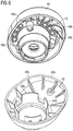
- a second embodiment of a first element 14 formed as a flange 18 made of a die-cast aluminum is shown, which is in the in Fig. 4 composite component 10 shown is used according to a second embodiment.
- the second embodiment of the composite component 10 differs from the first embodiment in the configuration of the second element 16.
- the second element 16 is designed as an upper part 40 for an air spring cup 13 and is connected to the flange 18 in a materially bonded manner.
- the flange 18 is inserted into an injection mold (not shown) and encapsulated with a plastic to form the upper part 40.
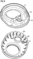
- Fig. 5 is an air spring component 12 according to a second embodiment with the in Fig. 4
- Composite component 10 shown as well as a lower part 42 are shown.
- the composite component 10 and the lower part 42 are materially connected to one another.
- the composite component 10 has a first joining area 44a and the lower part 42 has a second joining area 44b corresponding thereto.
- Both joining areas 44a, 44b are formed from an edge section 46a, 46b and a circular section 48a, 48b.
- the joining areas 44a, 44b can be materially connected to one another by means of hot gas welding.
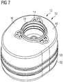
- FIG. 7 a third embodiment of an air spring component 12 designed as an air spring cup 13 is shown.
- the air spring component 12 comprises the in Fig. 4
- the composite component 10 shown has a middle part 50 and a lower part 52 which are connected to one another in a materially bonded manner.
- the composite component 10 has a joining area 54a and the central part 68 has a corresponding joining area 54b, each of which is formed from an edge section 56a, 56b, a circular section 58a, 58b and projections 60a, 60b.
- the central part 50 has a further joining region 62a and the lower part 52 has a joining region 62b corresponding thereto, which are formed from edge sections 64a, 64b.
- Fig. 10 shows an enlarged detail of a longitudinal section through a first embodiment of the joining areas 22a, 22b, 32a, 32b, 44a, 44b, 54a, 54b, 62a, 62b in the area of the edge sections 46a, 46b, 56a, 56b.
- the joining areas 22a, 22b, 32a, 32b, 44a, 44b, 54a, 54b, 62a, 62b each have a fusible projection 66 (left illustration in FIG Fig. 10 ).
- a weld seam cover 68 protrudes from one of the joining areas 22a, 22b, 32a, 32b, 44a, 44b, 54a, 54b, 62a, 62b.
- the meltable projections 66 are heated and / or melted or plasticized and pressed together by hot gas, infrared, mirror heating and / or induction, in order to produce a weld seam 70 (right illustration in FIG Fig. 10 ).
- the weld seam cover 68 makes contact with the other part and thereby covers a joint gap 72. As a result, no melt can escape, so that a clean outer surface is created.
- Fig. 11 an enlarged detail of a longitudinal section according to a second embodiment of the joining areas 22a, 22b, 32a, 32b, 44a, 44b, 54a, 54b, 62a, 62b is shown, which differs from the first embodiment in that the weld seam cover 68 is a tapering top lip 74 is formed (left representation of the Fig. 11 ), which, after being compressed, engages in a bevel 76 of the second part in order to cover the joint gap 72. This creates a smooth surface on the outside.
- the composite component 10 is distinguished by its combination of a flange 18 made of die-cast aluminum and a second element 16 made of a thermoplastic material which surrounds the flange 18 at least in some areas.
- the flange 18 is used to connect and transmit power to a motor vehicle part, and the second element 18 ensures sufficient tightness of the flange 18 made of die-cast aluminum.
- This allows the composite component 10 to be used in an air spring component, such as in an air spring cup 13 of an air spring strut.
- the second element 18 has joining geometries for the material connection of the composite component 10 with further components 28, 30, 42, 50, 52 to form an air spring cup 13.
Landscapes
- Engineering & Computer Science (AREA)
- Mechanical Engineering (AREA)
- General Engineering & Computer Science (AREA)
- Vehicle Body Suspensions (AREA)
- Lining Or Joining Of Plastics Or The Like (AREA)
- Fluid-Damping Devices (AREA)
Description
- Die vorliegende Erfindung betrifft ein Verbundbauteil für eine Luftfederkomponente eines Kraftfahrzeugs, insbesondere für einen Luftfedertopf eines Luftfederbeins eines Kraftfahrzeuges. Ferner betrifft die Erfindung eine Luftfederkomponente mit einem derartigen Verbundbauteil.
- Luftfedern dienen zur Abfederung zweier zueinander beweglicher Fahrzeugteile, aber auch zur Veränderung der Niveaulager eines Fahrzeugs. Luftfedern weisen einen mit Luft gefüllten Luftfederbalg aus Gummi auf, der luftdicht durch ein oberes Abschlusselement und einen Abrollkolben abgeschlossen ist. Das Abschlusselement und der Abrollkolben werden auch als Luftfederkomponenten bezeichnet. Über die Luftfederkomponenten erfolgt die Anbindung der Luftfeder an einem Kraftfahrzeugteil, wie beispielsweise der Fahrzeugkarosserie und/oder dem Fahrwerk. Die Luftfederkomponente kann dabei aus mehreren Teilen gebildet sein, die miteinander verbunden sind.
- Daneben finden Luftfedern in Kombination mit einem Schwingungsdämpfer in Luftfederbeinen Anwendung. Dabei übernimmt die Luftfeder die Federungsfunktion und der Schwingungsdämpfer die Dämpfungsfunktion. Zumeist werden als Schwingungsdämpfer Teleskopdämpfer verwendet, die einen mit Öl gefüllten Zylinder aufweisen, wobei eine Kolbenstange in den Zylinder einfährt und durch das Öl gedämpft wird. Die Luftfeder ist endseitig an dem Schwingungsdämpfer angeordnet und mit der Kolbenstange verbunden. Das obere Abschlusselement der Luftfeder ist dabei als Luftfedertopf ausgebildet, der über eine Anschlusseinrichtung zum Anschließen eines Kompressors verfügt. Über den Luftfedertopf erfolgt die Anbindung an einem Fahrzeugteil.
- Somit müssen Luftfederkomponenten und ihre Bestandteile eine ausreichende Festigkeit für die Kraftübertragung und zugleich eine ausreichende Dichtheit aufweisen.
- Aus
WO 01/61207 A1 - Ferner geht aus
DE 102011 050 103 A1 ein zweiteiliger Abrollkolben hervor, der ein Verbindungselement aufweist, das als in das Kunststoffmaterial des Kolbens eingespritzter metallischer Gewindebolzen ausgebildet ist. -
DE 10 2007 035 640 A1 offenbart einen Abrollkolben mit einem Unterteil, an dessen Boden eine Befestigungsaufnahme zentrisch angeformt ist, wobei in die Befestigungsaufnahme eine Mutter eingelegt werden kann. - Darüber hinaus geht aus
EP 2 031 268 A1 ein Abrollkolben hervor, der einen Befestigungsabschnitt aufweist, in den eine Gewindebuchse aus Metall eingeschraubt ist. -
US 2012/0291626 A1 offenbart einen Abrollkolben mit einer zentralen Öffnung, in
die ein Befestigungselement stoffschlüssig eingebracht ist, um den Abrollkolben
an dem Kraftfahrzeugteil zu befestigen. -
DE 202 10 955 U1 beschreibt eine gattungsgemäße Luftfeder eines Kraftfahrzeugs. Die Luftfeder umfasst ein oberes Verbindungselement. Das Verbindungselement weist eine ebene Scheibe aus Metall auf. Zudem umfasst das Verbindungselement einen Teller aus Kunststoff, zum Beispiel aus glasfaserverstärktem Nylon, der die Scheibe umgibt. -
DE 10 2013 212982 A1 betrifft einen Luftfederdeckel, der als Verbundbauteil ausgeführt ist. Er umfasst einen oberen, an der Fahrzeugkarosserie befestigten Teil und wenigstens einen unteren Teil, an welchem ein Luftfederbalg luftdicht befestigt ist. Der obere Teil kann ein Aluminiumgussteil sein und der untere Teil ist aus Stahl ausgebildet. - Der Erfindung liegt die Aufgabe zugrunde, ein Verbundbauteil für eine Luftfederkomponente sowie eine Luftfederkomponente zu schaffen, die sowohl eine verbesserte Festigkeit für die Kraftübertragung und gleichzeitig eine verbesserte Dichtheit aufweisen.
- Zur Lösung der Aufgabe werden ein Verbundbauteil sowie eine Luftfederkomponente mit den Merkmalen der unabhängigen Ansprüche vorgeschlagen.
- Vorteilhafte Ausgestaltungen des Verbundbauteils und der Luftfederkomponente sind Gegenstand der jeweiligen abhängigen Ansprüche.
- Das Verbundbauteil für eine als Luftfedertopf ausgebildete Luftfederkomponente eines Kraftfahrzeugs, insbesondere für einen Luftfedertopf eines Luftfederbeins eines Kraftfahrzeuges, weist ein erstes Element aus einem ersten Werkstoff aus Aluminiumdruckguss und ein zweites Element aus einem zweiten Werkstoff aus glasfaserverstärktem thermoplastischem Kunststoff auf, wobei das erste Element als Flansch zur Befestigung an einem Kraftfahrzeugteil ausgebildet ist, und wobei das zweite Element das erste Element zumindest bereichsweise umgibt. Das aus einem ersten Werkstoff gefertigte erste Element weist eine ausreichende Festigkeit auf und dient somit zur Anbindung und Kraftübertragung an einem Fahrzeugteil, wie beispielsweise der Fahrzeugkarosserie oder dem Fahrwerk. Das aus einem zweiten Werkstoff gefertigte und das erste Element zumindest bereichsweise umgebende zweite Element sorgt für eine ausreichende Dichtheit, insbesondere Gasdichtheit, des Verbundbauteils, so dass das Verbundbauteil für Luftfederanwendungen geeignet ist. Über den Flansch erfolgt die Kraftübertragung auf ein Kraftfahrzeugteil. Das Verbundbauteil kann auch als Hybridbauteil bezeichnet werden. Bevorzugt ist das Verbundbauteil mit weiteren Bauteilen zur Bildung einer Luftfederkomponente, insbesondere eines Luftfedertopfes, verbindbar. Das erste Element kann einteilig oder mehrteilig ausgebildet sein.
- Erfindungsgemäß ist der erste Werkstoff Aluminiumdruckguss. Ein aus Aluminiumdruckguss gebildeter Flansch weist eine ausreichende Festigkeit zur Kraftübertragung auf. Das erste Element kann ein Tiefziehteil oder ein Drehteil sein.
- Erfindungsgemäß ist zudem der zweite Werkstoff ein thermoplastischer glasfaserverstärkter Kunststoff, insbesondere ein spritzfähiger thermoplastischer Kunststoff. Der thermoplastische Kunststoff sorgt für die Sicherstellung einer ausreichenden Dichtheit eines aus Metall, insbesondere Aluminiumdruckguss, hergestellten ersten Elementes. Als thermoplastischer Kunststoff wird bevorzugt PA 66 GF 30 verwendet.
- In einer vorteilhaften Ausgestaltung ist das zweite Element stoffschlüssig und/oder formschlüssig mit dem ersten Element verbunden. Bevorzugt ist das zweite Element durch bereichsweises und/oder vollständiges Umspritzen des ersten Elements mit dem zweiten Element mit dem ersten Element verbunden. Hierzu kann das erste Element in eine Spritzgussform eingelegt werden und mit dem zweiten Element bereichsweise und/oder vollständig umspritzt werden, so dass das zweite Element stoffschlüssig mit dem ersten Element verbunden ist. Ferner kann das zweite Element als separates Bauteil hergestellt sein und mit dem ersten Element durch Kraftschluss, Formschluss und/oder Stoffschluss verbunden sein. So kann das zweite Element auf das erste Element aufgepresst und/oder mit dem ersten Element verschweißt sein.
- Weiterhin vorteilhaft ist das zweite Element als Beschichtung und/oder Verschlusselement ausgebildet. Ein als Beschichtung ausgebildetes zweites Element wird zumeist mittels Spritzgießen auf das erste Element aufgetragen beziehungsweise mit diesem verbunden. Ferner kann ein als Beschichtung ausgebildetes zweites Element auch als Anstrich auf das erste Element aufgebracht werden. Ein als Verschlusselement ausgebildetes zweites Element wird bevorzugt im Spritzgussverfahren hergestellt, indem das erste Element in eine Spritzgussform eingelegt und mit dem zweiten Element umspritzt wird, wobei das zweite Element das Verschlusselement ausbildet. Dabei übernimmt das zweite Element die Funktion eines Deckelelementes, um einen Luftfedertopf abzuschließen.
- Das zweite Element kann wenigstens einen Fügebereich zum Verbinden mit einem zweiten Bauteil aufweisen. Über den Fügebereich wird ein zweites Bauteil, wie beispielsweise ein Unterteil, ein Mittelteil und/oder Zwischenteil zur Bildung einer Luftfederkomponente, insbesondere eines Luftfedertopfes, mit dem Verbundbauteil verbunden. Vorteilhaft ist das Verbundbauteil stoffschlüssig mit dem zweiten Bauteil verbunden. Weiterhin vorteilhaft ist das Verbundbauteil mit dem zweiten Bauteil verschweißt. Vorteilhaft erfolgt das Verschweißen unter inerter Atmosphäre. Hierzu werden die Fügebereiche des Verbundbauteils und des zweiten Bauteils unter inerter Atmosphäre zunächst erwärmt und anschließend verpresst.
- In einer vorteilhaften Ausgestaltung weist der Fügebereich wenigstens einen aufschmelzbaren Vorsprung auf. Die Fügebereiche können direkt während des Umspritzens des ersten Elementes mit dem zweiten Element hergestellt sein. Ferner können die Fügebereiche eben sein, aber auch eine dreidimensionale Ausgestaltung aufweisen. Die aufschmelzbaren Vorsprünge können entweder durch Heißgas, Infrarot, Spiegelaufheizung und/oder Induktion erwärmt und/oder plastifiziert beziehungsweise aufgeschmolzen werden, die dann durch Verpressen und Erstarren mit einem weiteren erwärmten und/oder plastifizierten Fügebereich eine Schweißnaht ausbilden.
- Der Fügebereich ist vorteilhaft aus wenigstens einem Randabschnitt, Vorsprung, Rippe und/oder Steg des zweiten Elementes und/oder ersten Elementes gebildet. Bevorzugt ist der Fügebereich aus mehreren Randabschnitten, Vorsprüngen, Rippen und/oder Stege gebildet. Die Rippen und/oder Stege sorgen für eine ausreichende Stabilität und Steifigkeit des Verbundbauteils. Weiterhin vorteilhaft ragen die Rippen und/oder Stege von einer Gehäusewand radial nach innen und/oder außen ab. Dadurch kann das Bauteil so gestaltet werden, dass der Fügebereich bzw. die Verbindungsstelle sowohl am äußeren Umfang als auch am inneren Umfang des Bauteils angeordnet ist. Die Stege und/oder Rippen können eine näherungsweise T-förmige Grundform aufweisen. Dadurch kann die Oberfläche der Fügebereiche vergrößert werden.
- Weiterhin vorteilhaft weist das erste Element einen Aufnahmeabschnitt zur Aufnahme eines Einsatzes zur Führung einer Dämpferstange eines Schwingungsdämpfers auf. Vorteilhaft umfasst der Einsatz einen Flansch, der in dem Aufnahmeabschnitt einpressbar ist, ein Führungselement zum Führen der Dämpferstange und eine den Flansch und den Führungsabschnitt miteinander verbindende Membran. Vorteilhaft ist das zweite Element zur Abdichtung im Bereich des Aufnahmeabschnitts angeordnet. Weiterhin vorteilhaft ist das zweite Element zwischen dem ersten Element und dem in den Aufnahmeabschnitt eingepressten Einsatz angeordnet.
- Ferner betrifft die Erfindung eine Luftfederkomponente mit einem derartigen Verbundbauteil und wenigstens einem zweiten Bauteil, die stoffschlüssig miteinander verbunden sind. Dadurch wird eine Luftfederkomponente, insbesondere ein Luftfedertopf für eine Luftfeder eines Luftfederbeins eines Kraftfahrzeuges, geschaffen, die eine ausreichende Dichtheit und gleichzeitig eine ausreichende Festigkeit zur Kraftübertragung auf ein Fahrzeugteil aufweist. Ein Luftfederbein weist bevorzugt eine Luftfeder und einen Schwingungsdämpfer auf. Dabei übernimmt die Luftfeder die Federungsfunktion und der Schwingungsdämpfer die Dämpfungsfunktion. Zumeist werden als Schwingungsdämpfer Teleskopdämpfer verwendet, die einen mit Öl gefüllten Zylinder aufweisen, wobei eine Kolbenstange in den Zylinder einfährt und durch das Öl gedämpft wird. Die Luftfeder ist endseitig an dem Schwingungsdämpfer angeordnet und mit der Kolbenstange verbunden. Über die Luftfeder, insbesondere dem Luftfedertopf, erfolgt die Anbindung an einem Fahrzeugteil.
- In einer vorteilhaften Ausgestaltung erfolgt der Stoffschluss durch Erwärmen und/oder Aufschmelzen und anschließendem Verpressen von Fügebereichen der Bauteile unter inerter Atmosphäre. Die stoffschlüssige Verbindung der beiden Bauteile unter inerter Atmosphäre ermöglicht, eine aus mehreren Bauteilen bestehende druckführende Luftfederkomponente zu erzeugen, die im Bereich der Verbindungsstellen beziehungsweise Fügebereiche eine ausreichende Dichtheit, Festigkeit sowie Temperatur- und Alterungsbeständigkeit aufweist. Ferner gewährleistet die stoffschlüssige Verbindung unter inerter Atmosphäre eine große gestalterische Freiheit der Fügebereiche beziehungsweise der Verbindungsstellen. Ferner gewährleistet die stoffschlüssige Verbindung unter inerter Atmosphäre eine große gestalterische Freiheit der Fügebereiche beziehungsweise der Verbindungsstellen. Die Fügebereiche können sowohl am äußeren Umfang, insbesondere an den Randabschnitten des Bauteils als auch im Inneren des Bauteils angeordnet sein. Ferner können die Fügebereiche eben ausgebildet sein, aber auch eine dreidimensionale Ausgestaltung aufweisen. Zudem ist vorteilhaft keine Nachbearbeitung der Fügebereiche vor dem Fügen erforderlich. Des Weiteren schützt die inerte Atmosphäre vor einer Verunreinigung der Fügebereiche, da eine Oxidation und/oder Reaktion der zu fügenden Bereiche verhindert wird. Dadurch weist die Schweißnaht eine hohe Festigkeit und Dichtheit auf.
- In einer vorteilhaften Ausgestaltung erfolgt das Erwärmen mittels Heißgas, Infrarot, Spiegelaufheizung und/oder Induktion. Vorteilhaft erfolgt die Erwärmung entweder unter Vakuum oder unter Einsatz eines inerten Arbeitsgases, insbesondere Stickstoff, in einer entsprechenden Umhausung.
- In einer vorteilhaften Ausgestaltung weißt wenigstens eines der Bauteile eine Schweißnahtabdeckung auf, die einen Fügespalt abdeckt. Weiterhin vorteilhaft ragt die Schweißnahtabdeckung von dem Verbundbauteil und/oder dem zweiten Bauteil ab und liegt in einer korrespondierenden Aussparung des Verbundbauteils und/oder des zweiten Bauteils ein.
- Vorteilhaft ist die Schweißnahtabdeckung als eine umlaufende Verdecklippe ausgebildet. Die Verdecklippe ragt dabei von einem der Bauteile, vorzugsweise von dessen Gehäusewand ab. Beim Verpressen der beiden Bauteile kontaktiert die Verdecklippe das andere Bauteil bzw. dessen Gehäusewand und verdeckt dadurch einen Fügespalt. Somit verhindert die Verdecklippe einen Austritt der plastifizierten bzw. aufgeschmolzenen Fügebereiche während des Verpressens. Dadurch ist es nicht mehr erforderlich, die Schweißnaht aufwendig nachzubearbeiten, da eine saubere Außenfläche der Luftfederkomponente geschaffen wird. Weiterhin vorteilhaft ist die Schweißnahtabdeckung als spitz zulaufende Verdecklippe ausgebildet, die in eine korrespondierende Schräge am gegenüberliegenden Bauteil während des Verpressens eingreift. Vorteilhaft wird hierdurch eine weitestgehende glatte Außenfläche geschaffen.
- In einer vorteilhaften Ausgestaltung ist das Verbundbauteil als Oberteil ausgebildet und mit einem Unterteil stoffschlüssig zu einem Luftfedertopf verbunden. Weiterhin vorteilhaft ist zwischen dem Oberteil und dem Unterteil ein Mittelteil angeordnet, das stoffschlüssig mit dem Oberteil und dem Unterteil zu einem Luftfedertopf verbunden ist. Dadurch kann eine schaltbare Luftfeder realisiert werden. Vorteilhaft sind das Unterteil und/oder das Mittelteil aus Metall oder aus thermoplastischen Kunststoff, insbesondere aus glasfaserverstärktem thermoplastischem Kunststoff, hergestellt. Als thermoplastischer Kunststoff wird bevorzugt PA66GF30 verwendet. Die aus Kunststoff gefertigten Bauteile tragen zu einer Gewichtsreduzierung und damit einhergehend zu einer Kraftstoffeinsparung bei. Als Metall wird vorteilhaft Aluminium verwendet, das ebenfalls ein vergleichsweise geringes Gewicht aufweist.
- Nachfolgend werden das Verbundbauteil und die Luftfederkomponente anhand der beigefügten schematischen Zeichnungen näher erläutert. Hierbei zeigen:
- Fig. 1
- einen Längsschnitt durch ein Verbundbauteil gemäß einer ersten Ausführungsform für eine als Luftfedertopf ausgebildete Luftfederkomponente;
- Fig. 2
- einen Längsschnitt durch eine als Luftfedertopf ausgebildete Luftfederkomponente gemäß einer ersten Ausführunsgsform mit dem in
Fig. 1 gezeigten Verbundbauteil; - Fig. 3
- eine perspektivische Darstellung eines ersten Elements für ein Verbundbauteil;
- Fig. 4
- eine perspektivische Darstellung eines Verbundbauteils gemäß einer zweiten Ausführungsform mit dem in
Fig. 3 gezeigten ersten Element; - Fig. 5
- eine perspektivische Darstellung der einzelnen Bauteile einer als Luftfedertopf ausgebildeten Luftfederkomponente gemäß einer zweiten Ausführungsform mit dem in
Fig. 4 gezeigten Verbundbauteil; - Fig. 6
- eine perspektivische Darstellung der in
Fig. 5 gezeigten Bauteile der Luftfederkomponente mit ihren Fügebereichen; - Fig. 7
- eine perspektivische Darstellung der einzelnen Bauteile einer als Luftfedertopf ausgebildeten Luftfederkomponente gemäß einer dritten Ausführungsform mit den in
Fig. 4 gezeigten Verbundbauteil; - Fig. 8
- eine perspektivische Darstellung des in
Fig. 5 gezeigten Verbundbauteils und Mittelteils mit ihren Fügebereichen; - Fig. 9
- eine perspektivische Darstellung des in
Fig. 5 gezeigten Mittelteils und Unterteils mit ihren Fügebereichen; - Fig. 10
- einen vergrößerten Ausschnitt eines Längsschnitts durch einen Fügebereich gemäß einer ersten Ausführungsform; und
- Fig. 11
- einen vergrößerten Ausschnitt eines Längsschnitts durch einen Fügebereicht gemäß einer zweiten Ausführungsform.
- In
Fig. 1 ist ein Verbundbauteil 10 gemäß einer ersten Ausführungsform im Längsschnitt dargestellt, das bei einer inFig. 2 dargestellten Luftfederkomponente 12 gemäß einer ersten Ausführungsform eingesetzt wird. Die Luftfederkomponente 12 ist als Luftfedertopf 13 für eine Luftfeder eines Luftfederbeins eines Kraftfahrzeuges ausgebildet. - Das Verbundbauteil 10, das auch als Hybridbauteil bezeichnet wird, weist ein erstes Element 14 aus einem ersten Werkstoff und ein zweites Element 16 aus einem zweiten Werkstoff auf.
- Das erste Element 14 ist als Flansch 18 zur Befestigung an einem nicht dargestellten Kraftfahrzeugteil ausgebildet und ist aus einem Metall, insbesondere Aluminiumdruckguss, hergestellt. Ferner weist das erste Element 14 einen Befestigungsabschnitt 23 zum Befestigen an einem nicht dargestellten Kraftfahrzeugteil und einen Aufnahmeabschnitt 24 zur Aufnahme eines in
Fig. 2 dargestellten Einsatzes 26 auf. - Das zweite Element 18 ist als Beschichtung 20 ausgebildet, die das erste Element 14 bereichsweise umgibt. Das zweite Element 18 ist aus einem thermoplastischen Kunststoff, wie beispielsweise PA 66 GF 30. Die Beschichtung 20 ist stoffschlüssig mit dem Flansch 18 verbunden. Hierzu wird der Flansch 18 in eine nicht dargestellte Spritzgussform eingelegt und mit einem thermoplastischen Kunststoff umspritzt. Die Beschichtung 20 sorgt dabei für eine ausreichende Dichtheit des Flansches 18, so dass das Verbundbauteil 10 für eine Luftfederanwendung geeignet ist. Ferner weist das zweite Element 18 einen Fügebereich 22a zum Verbinden mit einem zweiten Bauteil auf. Der Fügebereich 22a wird während des Umspritzens des ersten Elementes 14 mit dem zweiten Element 16 ausgebildet und kann eben oder dreidimensional sein.
- Die in
Fig. 2 dargestellte Luftfederkomponente 12 weist das Verbundbauteil 10, ein Mittelteil 28 und ein Unterteil 30 auf, die stoffschlüssig zu dem Luftfedertopf 13 miteinander verbunden sind. Das Mittelteil 28 und das Unterteil 30 sind aus einem Kunststoff, insbesondere einem thermoplastischen Kunststoff, wie beispielsweise PA 66 GF 30, hergestellt. Das Mittelteil 28 weist einen zu dem Fügebereich 22a des zweiten Elements 16 korrespondierenden zweiten Fügebereich 22b auf. Ferner weist das Mittelteil 28 einen weiteren Fügebereich 32a auf, der mit einem korrespondierende Fügebereich 32b des Unterteils 30 verbunden ist. Über die Fügebereiche 22a, 22b, 32a, 32b erfolgt die stoffschlüssige Verbindung der Teile 10, 28, 30 zu der Luftfederkomponente 12. So können die Teile 10, 28, 30 mittels Heißgasschweißen miteinander verbunden werden, indem die Fügebereiche 22a, 22b, 32a, 32b erwärmt und/oder aufgeschmolzen bzw. plastifiziert und anschließend zusammengedrückt werden. Nach dem Erstarren der Fügebereiche 22a, 22b, 32a, 32b sind unter Ausbildung einer nicht dargestellten Schweißnaht die Teile 10, 28, 30 stoffschlüssig miteinander verbunden. Beim Heißgasschweißen werden die Fügebereiche 22a, 22b, 32a, 32b mittels eines Heißgases erwärmt und/oder aufgeschmolzen beziehungsweise plastifiziert, wobei bevorzugt Stickstoff als Arbeitsgas verwendet wird. - Ferner wird in den Aufnahmeabschnitt 24 der Einsatz 26 eingepresst. Zur Sicherstellung einer ausreichenden Dichtheit ist der Aufnahmeabschnitt 24 mit der Beschichtung 20 versehen. Der Einsatz 26 weist ein Führungselement 34 zur Führung einer nicht dargestellten Dämpferstange, ein Flanschelement 36 zum Einpressen in den Aufnahmeabschnitt 24 und eine das Führungselement 34 und das Flanschelement 36 miteinander verbindende Membran 32 auf.
- In
Fig. 3 ist eine zweite Ausführungsform eines als Flansch 18 ausgebildeten ersten Elementes 14 aus einem Aluminiumdruckguss dargestellt, der in dem inFig. 4 gezeigten Verbundbauteil 10 gemäß einer zweiten Ausführungsform verwendet wird. Die zweite Ausführungsform des Verbundbauteils 10 unterscheidet sich von der ersten Ausführungsform in der Ausgestaltung des zweiten Elements 16. Das zweite Element 16 ist als Oberteil 40 für einen Luftfedertopf 13 ausgebildet und ist stoffschlüssig mit dem Flansch 18 verbunden. Hierzu wird der Flansch 18 in eine nicht dargestellte Spritzgussform eingelegt und mit einem Kunststoff zur Ausbildung des Oberteils 40 umspritzt. - In
Fig. 5 ist eine Luftfederkomponente 12 gemäß einer zweiten Ausführungsform mit dem inFig. 4 gezeigten Verbundbauteil 10 sowie einem Unterteil 42 gezeigt. Das Verbundbauteil 10 und das Unterteil 42 sind stoffschlüssig miteinander verbunden. Wie inFig. 6 dargestellt ist, weist das Verbundbauteil 10 einen ersten Fügebereich 44a und das Unterteil 42 einen dazu korrespondierenden zweiten Fügebereich 44b auf. Beide Fügebereiche 44a, 44b sind aus einem Randabschnitt 46a, 46b und einem Kreisabschnitt 48a, 48b gebildet. Die Fügebereiche 44a, 44b können mittels Heißgasschweißen stoffschlüssig miteinander verbunden. - In
Fig. 7 ist eine dritte Ausführungsform einer als Luftfedertopf 13 ausgebildeten Luftfederkomponente 12 dargestellt. Die Luftfederkomponente 12 umfasst das inFig. 4 gezeigte Verbundbauteil 10 ein Mittelteil 50 und ein Unterteil 52, die stoffschlüssig miteinander verbunden sind. Wie inFig. 8 gezeigt ist, weist das Verbundbauteil 10 einen Fügebereich 54a und das Mittelteil 68 einen dazu korrespondierenden Fügebereich 54b auf, die jeweils aus einem Randabschnitt 56a, 56b einen Kreisabschnitt 58a, 58b und Vorsprüngen 60a, 60b gebildet sind. Ferner weist, wie inFig. 9 dargestellt ist, das Mitteilteil 50 einen weiteren Fügebereich 62a und das Unterteil 52 einen dazu korrespondierenden Fügebereich 62b auf, die aus Randabschnitten 64a, 64b gebildet sind. - In
Fig. 10 ist ein vergrößerter Ausschnitt eines Längsschnitts durch eine erste Ausführungsform der Fügebereiche 22a, 22b, 32a, 32b, 44a, 44b, 54a, 54b, 62a, 62b im Bereich der Randabschnitte 46a, 46b, 56a, 56b dargestellt. Die Fügebereiche 22a, 22b, 32a, 32b, 44a, 44b, 54a, 54b, 62a, 62b weisen jeweils einen aufschmelzbaren Vorsprung 66 auf (linke Darstellung derFig. 10 ). Ferner ragt von einem der Fügebereiche 22a, 22b, 32a, 32b, 44a, 44b, 54a, 54b, 62a, 62b eine Schweißnahtabdeckung 68 ab. Die aufschmelzbaren Vorsprünge 66 werden durch Heißgas, Infrarot, Spiegelaufheizung und/oder Induktion erwärmt und/oder aufgeschmolzen bzw. plastifiziert und zusammengedrückt, um so eine Schweißnaht 70 zu erzeugen (rechte Darstellung derFig. 10 ). Beim Zusammendrücken kontaktiert die Schweißnahtabdeckung 68 das andere Teil und verdeckt dabei einen Fügespalt 72. Dadurch kann keine Schmelze austreten, so dass eine saubere Außenfläche geschaffen wird. - In
Fig. 11 ist vergrößerter Ausschnitt eines Längsschnittes gemäß einer zweiten Ausführungsform der Fügebereiche 22a, 22b, 32a, 32b, 44a, 44b, 54a, 54b, 62a, 62b dargestellt, die sich von der ersten Ausführungsform dadurch unterscheidet, dass die Schweißnahtabdeckung 68 als spitz zulaufende Verdecklippe 74 ausgebildet ist (linke Darstellung derFig. 11 ), die nach dem Zusammendrücken in eine Schräge 76 des zweiten Teils eingreift, um so den Fügespalt 72 zu verdecken. Dadurch wird nach außen hin eine glatte Fläche geschaffen. - Das Verbundbauteil 10 zeichnet sich durch seine Kombination aus einem Flansch 18 aus Aluminiumdruckguss und einem den Flansch 18 zumindest bereichsweise umgebenden zweiten Element 16 aus einem thermoplastischen Kunststoff aus. Über den Flansch 18 erfolgt die Anbindung und Kraftübertragung an einem Kraftfahrzeugteil und das zweite Element 18 gewährleistet eine ausreichende Dichtheit des aus Aluminiumdruckguss hergestellten Flansches 18. Dadurch kann das Verbundbauteil 10 in einer Luftfederkomponente, wie beispielsweise in einem Luftfedertopf 13 eines Luftfederbeins, eingesetzt werden. Ferner weist das zweite Element 18 Fügegeometrien zum stoffschlüssigen Verbinden des Verbundbauteils 10 mit weiteren Bauteilen 28, 30, 42, 50, 52 zu einem Luftfedertopf 13 auf.
-
- 10
- Verbundbauteil
- 12
- Luftfederkomponente
- 13
- Luftfedertopf
- 14
- erste Element
- 16
- zweite Element
- 18
- Flansch
- 20
- Beschichtung
- 22a
- Fügebereich
- 22b
- Fügebereich
- 23
- Befestigungsabschnitt
- 24
- Aufnahmeabschnitt
- 26
- Einsatz
- 28
- Mittelteil
- 30
- Unterteil
- 32a
- Fügebereich
- 32b
- Fügebereich
- 34
- Führungselement
- 36
- Flanschelement
- 38
- Membran
- 40
- Oberteil
- 42
- Unterteil
- 44a
- Fügebereich
- 44b
- Fügebereich
- 46a
- Randabschnitt
- 46b
- Randabschnitt
- 48a
- Kreisabschnitt
- 48b
- Kreisabschnitt
- 50
- Mittelteil
- 52
- Unterteil
- 54a
- Fügebereich
- 54b
- Fügebereich
- 56a
- Randabschnitt
- 56b
- Randabschnitt
- 58a
- Kreisabschnitt
- 58b
- Kreisabschnitt
- 60a
- Vorsprung
- 60b
- Vorsprung
- 62a
- Fügebereich
- 62b
- Fügebereich
- 64a
- Randabschnitt
- 64b
- Randabschnitt
- 66
- Vorsprung
- 68
- Schweißnahtabdeckung
- 70
- Schweißnaht
- 72
- Fügespalt
- 74
- Verdecklippe
- 76
- Schräge
Claims (13)
- Verbundbauteil (10) für eine als Luftfedertopf ausgebildete Luftfederkomponente (12) eines Kraftfahrzeuges mit einem ersten Element (14) aus einem ersten Werkstoff aus Aluminiumdruckguss und einem zweiten Element (16) aus einem zweiten Werkstoff aus glasfaserverstärktem thermoplastischem Kunststoff, wobei das erste Element (14) als Flansch (18) zur Befestigung an einem Kraftfahrzeugteil ausgebildet ist, und wobei das zweite Element (16) das erste Element (14) zumindest bereichsweise umgibt.
- Verbundbauteil nach Anspruch 1, dadurch gekennzeichnet, dass das zweite Element (16) stoffschlüssig und/oder formschlüssig mit dem ersten Element (14) verbunden ist.
- Verbundbauteil nach Anspruch 1 oder 2, dadurch gekennzeichnet, dass das zweite Element (16) als Beschichtung (20) und/oder Verschlusselement (40) ausgebildet ist.
- Verbundbauteil nach einem der vorhergehenden Ansprüche, dadurch gekennzeichnet, dass das zweite Element (16) wenigstens einen Fügebereich (22a, 44a, 54a) zum Verbinden mit einem zweiten Bauteil (28, 42, 50) aufweist.
- Verbundbauteil nach Anspruch 4, dadurch gekennzeichnet, dass der Fügebereich (22a, 44a, 54a) wenigstens einen aufschmelzbaren Vorsprung (66) aufweist.
- Verbundbauteil nach Anspruch 4 oder 5, dadurch gekennzeichnet, dass der Fügebereich (22a, 44a, 54a) aus wenigstens einem Randabschnitt (46a, 56a), Vorsprung (60a), Rippe und/oder Steg gebildet ist.
- Verbundbauteil nach einem der vorhergehenden Ansprüche, dadurch gekennzeichnet, dass das erste Element (14) einen Aufnahmeabschnitt (24) zur Aufnahme eines Einsatzes (26) zur Führung einer Dämpferstange eines Schwingungsdämpfers aufweist.
- Verbundbauteil nach einem der vorhergehenden Ansprüche, dadurch gekennzeichnet, dass der zweite Werkstoff ein spritzfähiger thermoplastischer Kunststoff ist.
- Luftfederkomponente (12) mit einem Verbundbauteil (10) nach einem der Ansprüche 1 bis 8 und wenigstens einem zweiten Bauteil (28, 42, 50), die stoffschlüssig miteinander verbunden sind.
- Luftfederkomponente nach Anspruch 9, dadurch gekennzeichnet, dass der Stoffschluss durch Erwärmen und/oder Aufschmelzen und anschließendem Verpressen von Fügebereichen (22a, 22b, 44a, 44b, 54a, 54b) der Bauteile (10, 28, 42, 50) unter inerter Atmosphäre erfolgt.
- Luftfederkomponente nach einem der Ansprüche 9 oder 10, dadurch gekennzeichnet, dass wenigstens eines der Bauteile (10, 28, 42, 50) eine Schweißnahtabdeckung (68) aufweist, die einen Fügespalt (72) abdeckt.
- Luftfederkomponente nach einem der Ansprüche 9 bis 11, dadurch gekennzeichnet, dass das Verbundbauteil (10) als Oberteil (10, 40) ausgebildet ist und mit einem Unterteil (30, 42, 52) stoffschlüssig zu einem Luftfedertopf (13) verbunden ist.
- Luftfederkomponente nach Anspruch 12, dadurch gekennzeichnet, dass zwischen dem Oberteil (10, 40) und dem Unterteil (30, 52) ein Mittelteil (28, 50) angeordnet ist, das stoffschlüssig mit dem Oberteil (10, 40) und dem Unterteil (30, 52) zu einem Luftfedertopf (13) verbunden ist.
Applications Claiming Priority (2)
| Application Number | Priority Date | Filing Date | Title |
|---|---|---|---|
| DE102015100281.7A DE102015100281A1 (de) | 2015-01-09 | 2015-01-09 | Verbundbauteil sowie Luftfederkomponente mit einem derartigen Verbundbauteil |
| PCT/EP2015/076984 WO2016110357A1 (de) | 2015-01-09 | 2015-11-18 | Verbundbauteil sowie luftfederkomponente mit einem derartigen verbundbauteil |
Publications (3)
| Publication Number | Publication Date |
|---|---|
| EP3242806A1 EP3242806A1 (de) | 2017-11-15 |
| EP3242806B1 true EP3242806B1 (de) | 2021-07-21 |
| EP3242806B2 EP3242806B2 (de) | 2025-07-16 |
Family
ID=54548201
Family Applications (1)
| Application Number | Title | Priority Date | Filing Date |
|---|---|---|---|
| EP15795205.2A Active EP3242806B2 (de) | 2015-01-09 | 2015-11-18 | Verbundbauteil sowie luftfederkomponente mit einem derartigen verbundbauteil |
Country Status (7)
| Country | Link |
|---|---|
| US (1) | US10525782B2 (de) |
| EP (1) | EP3242806B2 (de) |
| JP (1) | JP6483840B2 (de) |
| KR (1) | KR102068690B1 (de) |
| CN (1) | CN107107697B (de) |
| DE (1) | DE102015100281A1 (de) |
| WO (1) | WO2016110357A1 (de) |
Families Citing this family (13)
| Publication number | Priority date | Publication date | Assignee | Title |
|---|---|---|---|---|
| DE102014212788A1 (de) * | 2014-07-02 | 2016-01-07 | Bayerische Motoren Werke Aktiengesellschaft | Luftausgleichsbehälter |
| EP3317557B1 (de) * | 2015-07-01 | 2020-01-01 | Firestone Industrial Products Company, LLC | Klemmplatte, luftfedervorrichtungen und diese betreffende verfahren |
| DE102016122155A1 (de) * | 2016-11-17 | 2018-05-17 | Vibracoustic Gmbh | Dämpferlager und Verfahren zum Herstellen eines Dämpferlagers |
| DE102017216052A1 (de) | 2016-11-24 | 2018-05-24 | Continental Teves Ag & Co. Ohg | Luftfederbein mit einem Luftfederdeckel mit Bajonettverschluss |
| DE102018216992B4 (de) | 2017-10-04 | 2021-11-04 | Continental Teves Ag & Co. Ohg | Luftfederbein mit Verstärkungseinsatz im Deckel |
| DE102018216993A1 (de) | 2017-10-04 | 2019-04-04 | Continental Teves Ag & Co. Ohg | Luftfeder mit Anschlussteil aus Duroplast |
| CN111433486B (zh) * | 2017-12-01 | 2022-05-10 | 大陆-特韦斯贸易合伙股份公司及两合公司 | 盖中具有加强芯的空气弹簧滑柱组件 |
| DE102018216717B4 (de) * | 2018-09-28 | 2025-03-27 | Continental Automotive Technologies GmbH | Luftfederbein mit einem Kunststoff-Luftfederdeckel aus Thermoplast |
| CN111795098B (zh) * | 2020-05-25 | 2021-11-02 | 中国第一汽车股份有限公司 | 一种空气弹簧总成 |
| DE102020134375A1 (de) * | 2020-12-21 | 2022-06-23 | Vibracoustic Se | Bauteil insbesondere für eine Luftfeder, ein Luftfederbein, einen Luftfederdämpfer oder ein Topmountgehäuse und Verfahren zum Herstellen des Bauteils |
| CN113757301A (zh) * | 2021-09-27 | 2021-12-07 | 上海保隆汽车科技(安徽)有限公司 | 一种空气弹簧的上气室结构 |
| EP4474179B1 (de) * | 2023-06-07 | 2025-08-20 | Hyundai Mobis Co., Ltd. | Obere anschlussvorrichtung für eine luftfederung |
| CN119022016A (zh) * | 2024-10-29 | 2024-11-26 | 宁波永金汽车部件有限公司 | 一种气室端盖组件、生产方法及其空气弹簧 |
Citations (22)
| Publication number | Priority date | Publication date | Assignee | Title |
|---|---|---|---|---|
| JP3169153B2 (ja) | 1993-12-28 | 2001-05-21 | トヨタ自動車株式会社 | プラスチック部材の接合方法 |
| DE20210955U1 (de) * | 2002-07-19 | 2002-09-19 | C.F. Gomma S.p.A., Passirano, Brescia | Oberes Verbindungselement für eine Luftfeder eines Kraftfahrzeugs |
| DE10216175C1 (de) | 2002-04-12 | 2003-07-24 | Stiebel Eltron Gmbh & Co Kg | Bauteil, insbesondere Behälter oder Rohr, und Verfahren zur Herstellung eines Behälters |
| EP1426648A1 (de) | 2002-12-06 | 2004-06-09 | Continental Aktiengesellschaft | Mit Extravolumen versehener Luftfederdeckel und Verfahren zu seiner Herstellung |
| DE10347934A1 (de) * | 2002-11-29 | 2004-06-09 | Phoenix Ag | Luftfederanordnung |
| DE102004015881A1 (de) | 2003-04-09 | 2004-12-23 | Aisan Kogyo K.K., Obu | Einlassverteiler aus Harz |
| EP1602468A2 (de) | 2004-05-26 | 2005-12-07 | Toyota Boshoku Kabushiki Kaisya | Verbindungsstruktur für Druckausgleichgefäss , Druckausgleichgefäss und Einlasskammer |
| DE102004061989A1 (de) | 2004-12-23 | 2006-07-06 | Continental Aktiengesellschaft | Luftfeder eines Kraftfahrzeugs |
| US20070096374A1 (en) * | 2004-06-23 | 2007-05-03 | Karsten Scholz | Air spring having a roll-off piston and a rolling-lobe flexible member having at least one attachment part vulcanized thereon |
| DE102006010815A1 (de) | 2006-03-07 | 2007-09-13 | Geiger Technik Gesellschaft mit beschränkter Haftung | Gehäuse aus thermoplastischem Kunststoff und Verfahren zu seiner Herstellung |
| DE102007026826A1 (de) | 2007-06-06 | 2008-12-11 | Mann + Hummel Gmbh | Ansaugsystem |
| DE102007035640A1 (de) | 2007-07-27 | 2009-01-29 | Lkh-Kunststoffwerk Gmbh & Co. Kg | Tauchkolben |
| JP2009127682A (ja) | 2007-11-21 | 2009-06-11 | Fukoku Co Ltd | 空気ばね |
| EP2153977A2 (de) | 2008-08-11 | 2010-02-17 | ElringKlinger AG | Baugruppe mit miteinander verschweissten Kunststoffteilen sowie Verfahren zu ihrer Herstellung |
| DE102008048793A1 (de) | 2008-09-24 | 2010-03-25 | Mann + Hummel Gmbh | Verfahren zur Herstellung einer Kunststoffölwanne mittels Heißgasschweißen |
| DE102009049047A1 (de) | 2008-11-13 | 2010-06-10 | MANDO CORPORATION, Pyeongtaek | Halterung zur Befestigung eines Schwingungsdämpfers |
| DE102010004204A1 (de) | 2010-01-08 | 2011-08-25 | Trelleborg Automotive Germany GmbH, 56203 | Verfahren zur Herstellung einer Nut an einem Lagergehäuse sowie gemäß dem Verfahren hergestelltes Lagergehäuse und Federbeinstützlger mit dem erfindungsgemäßen Lagergehäuse |
| JP4948004B2 (ja) | 2006-03-16 | 2012-06-06 | 東京濾器株式会社 | 樹脂製ケースと樹脂製カバーとの振動溶着構造 |
| DE102013219912A1 (de) | 2012-10-01 | 2014-04-03 | Firestone Industrial Products Company LLC | Endelement und Gasfederanordnung, welche dasselbe aufweist |
| DE102012110112A1 (de) | 2012-10-23 | 2014-04-24 | a.i.m. GmbH Werkzeugbau - Stanz + Fügetechnik | Gasfedertopf für eine Gasfeder-Stoßdämpfereinrichtung |
| DE102013212982A1 (de) * | 2012-11-22 | 2014-06-05 | Continental Teves Ag & Co. Ohg | Luftfedereinheit |
| EP2775162A2 (de) | 2013-03-08 | 2014-09-10 | Veyance Technologies, Inc. | Verbundstoffwulstplatte und Luftfeder damit |
Family Cites Families (33)
| Publication number | Priority date | Publication date | Assignee | Title |
|---|---|---|---|---|
| US4104089A (en) * | 1976-07-08 | 1978-08-01 | Nippon Light Metal Company Limited | Die-cast aluminum alloy products |
| US4796870A (en) * | 1987-05-18 | 1989-01-10 | The Firestone Tire & Rubber Company | Suspension system for vehicles containing combination isolator mount and air spring closure |
| US5005808A (en) * | 1987-12-01 | 1991-04-09 | The Goodyear Tire & Rubber Company | Airspring end member and airspring assembly |
| US4988082A (en) * | 1989-07-18 | 1991-01-29 | General Motors Corporation | Spliced air sleeve assembly for air spring damper |
| US5752692A (en) | 1997-01-06 | 1998-05-19 | The Gates Corporation | Side load compensating airspring strut |
| US6199837B1 (en) * | 1998-05-01 | 2001-03-13 | Bridgestone/Firestone, Inc. | Thermoplastic elastomer air spring |
| US6386524B1 (en) * | 2000-02-15 | 2002-05-14 | Bfs Diversified Products, Llc | Pedestal mounted full reservoir air spring piston |
| JP2002364469A (ja) * | 2001-06-04 | 2002-12-18 | Keihin Corp | 車両用吸気マニホールドの製造方法 |
| US6843472B2 (en) * | 2003-01-21 | 2005-01-18 | The Pullman Company | Upper shock mount isolator with integral air spring housing pivot bearing |
| DE10315679A1 (de) * | 2003-04-07 | 2004-10-21 | Bayerische Motoren Werke Ag | Luftfederbein für ein Kraftfahrzeug |
| JP2004316468A (ja) * | 2003-04-11 | 2004-11-11 | Aisan Ind Co Ltd | 樹脂製インテークマニホールド |
| DE102004060727A1 (de) | 2004-12-17 | 2006-07-06 | Vibracoustic Gmbh & Co. Kg | Luftfeder und Verfahren zur Abdichtung einer Luftfeder |
| ITMI20050211A1 (it) | 2005-02-14 | 2006-08-15 | Stuani S P A | Pistone perfezionato per molle ad aria applicabile a sospensioni di autoveicoli rimorchi semirimorchi |
| US7773172B2 (en) * | 2005-03-01 | 2010-08-10 | Northrop Grumman Corporation | Line attenuation tunable optical filter |
| JP2007111926A (ja) * | 2005-10-19 | 2007-05-10 | Toyota Motor Corp | 熱可塑性樹脂部材のレーザ溶着方法およびレーザ溶着装置 |
| DE102006009301A1 (de) * | 2006-03-01 | 2007-09-06 | Daimlerchrysler Ag | Einzelradaufhängung mit fahrwerksversteifenden Gas- oder Hydraulikfederungsteilen |
| ITTO20060083U1 (it) | 2006-05-31 | 2007-12-01 | Gomma C F Spa | Pistone di una molla ad aria per un autoveicolo di tipo assemblato |
| JP2007321936A (ja) | 2006-06-05 | 2007-12-13 | Fukoku Co Ltd | 空気ばね |
| DE102006036248A1 (de) * | 2006-08-03 | 2008-02-07 | Continental Aktiengesellschaft | Luftfeder für Fahrzeuge |
| DE102006043471A1 (de) * | 2006-09-15 | 2008-03-27 | Continental Aktiengesellschaft | Luftfederbein |
| AU2009268495B2 (en) | 2008-07-09 | 2014-04-17 | Firestone Industrial Products Company, Llc | Gas spring and gas damper assembly and method |
| KR100917557B1 (ko) * | 2008-08-19 | 2009-09-16 | 현대모비스 주식회사 | 에어 현가 장치의 에어 스프링 장치 |
| JP2010090989A (ja) * | 2008-10-08 | 2010-04-22 | Bridgestone Corp | 空気ばね |
| JP5277080B2 (ja) * | 2009-06-08 | 2013-08-28 | 東洋ゴム工業株式会社 | 空気ばね |
| EP2467272A1 (de) * | 2009-08-19 | 2012-06-27 | Aktas Hava Süspansiyon Sistemleri Sanay Ve Ticaret Anonim Sirketi | Dämpfer für luftfeder |
| DE102011050103A1 (de) | 2011-05-04 | 2012-11-08 | Contitech Luftfedersysteme Gmbh | Abrollkolben für einen Luftfederrollbalg |
| WO2012158793A1 (en) | 2011-05-17 | 2012-11-22 | Hendrickson Usa, L.L.C. | Piston for an air spring of a heavy-duty vehicle |
| DE102012012902A1 (de) * | 2011-07-11 | 2013-01-17 | Contitech Vibration Control Gmbh | Luftfedermodul |
| DE102012015032B4 (de) | 2012-07-31 | 2022-09-29 | Man Truck & Bus Se | Abrollkolben für ein Gasfedersystem von Fahrzeugen |
| US9140327B2 (en) * | 2012-08-31 | 2015-09-22 | Firestone Industrial Products Company, Llc | End member assemblies and gas spring assemblies including same |
| DE102013106290B3 (de) * | 2013-06-17 | 2014-10-16 | Vibracoustic Cv Air Springs Gmbh | Luftfederbefestigungssystem |
| DE102013113737A1 (de) | 2013-12-10 | 2015-06-11 | Trelleborgvibracoustic Gmbh | Luftfederkomponente |
| JP5766836B1 (ja) * | 2014-03-12 | 2015-08-19 | 住友理工株式会社 | 車両用ダストカバー組付体およびその製造方法 |
-
2015
- 2015-01-09 DE DE102015100281.7A patent/DE102015100281A1/de active Pending
- 2015-11-18 CN CN201580072371.3A patent/CN107107697B/zh active Active
- 2015-11-18 KR KR1020177018918A patent/KR102068690B1/ko not_active Expired - Fee Related
- 2015-11-18 JP JP2017536326A patent/JP6483840B2/ja not_active Expired - Fee Related
- 2015-11-18 US US15/541,717 patent/US10525782B2/en active Active
- 2015-11-18 EP EP15795205.2A patent/EP3242806B2/de active Active
- 2015-11-18 WO PCT/EP2015/076984 patent/WO2016110357A1/de not_active Ceased
Patent Citations (22)
| Publication number | Priority date | Publication date | Assignee | Title |
|---|---|---|---|---|
| JP3169153B2 (ja) | 1993-12-28 | 2001-05-21 | トヨタ自動車株式会社 | プラスチック部材の接合方法 |
| DE10216175C1 (de) | 2002-04-12 | 2003-07-24 | Stiebel Eltron Gmbh & Co Kg | Bauteil, insbesondere Behälter oder Rohr, und Verfahren zur Herstellung eines Behälters |
| DE20210955U1 (de) * | 2002-07-19 | 2002-09-19 | C.F. Gomma S.p.A., Passirano, Brescia | Oberes Verbindungselement für eine Luftfeder eines Kraftfahrzeugs |
| DE10347934A1 (de) * | 2002-11-29 | 2004-06-09 | Phoenix Ag | Luftfederanordnung |
| EP1426648A1 (de) | 2002-12-06 | 2004-06-09 | Continental Aktiengesellschaft | Mit Extravolumen versehener Luftfederdeckel und Verfahren zu seiner Herstellung |
| DE102004015881A1 (de) | 2003-04-09 | 2004-12-23 | Aisan Kogyo K.K., Obu | Einlassverteiler aus Harz |
| EP1602468A2 (de) | 2004-05-26 | 2005-12-07 | Toyota Boshoku Kabushiki Kaisya | Verbindungsstruktur für Druckausgleichgefäss , Druckausgleichgefäss und Einlasskammer |
| US20070096374A1 (en) * | 2004-06-23 | 2007-05-03 | Karsten Scholz | Air spring having a roll-off piston and a rolling-lobe flexible member having at least one attachment part vulcanized thereon |
| DE102004061989A1 (de) | 2004-12-23 | 2006-07-06 | Continental Aktiengesellschaft | Luftfeder eines Kraftfahrzeugs |
| DE102006010815A1 (de) | 2006-03-07 | 2007-09-13 | Geiger Technik Gesellschaft mit beschränkter Haftung | Gehäuse aus thermoplastischem Kunststoff und Verfahren zu seiner Herstellung |
| JP4948004B2 (ja) | 2006-03-16 | 2012-06-06 | 東京濾器株式会社 | 樹脂製ケースと樹脂製カバーとの振動溶着構造 |
| DE102007026826A1 (de) | 2007-06-06 | 2008-12-11 | Mann + Hummel Gmbh | Ansaugsystem |
| DE102007035640A1 (de) | 2007-07-27 | 2009-01-29 | Lkh-Kunststoffwerk Gmbh & Co. Kg | Tauchkolben |
| JP2009127682A (ja) | 2007-11-21 | 2009-06-11 | Fukoku Co Ltd | 空気ばね |
| EP2153977A2 (de) | 2008-08-11 | 2010-02-17 | ElringKlinger AG | Baugruppe mit miteinander verschweissten Kunststoffteilen sowie Verfahren zu ihrer Herstellung |
| DE102008048793A1 (de) | 2008-09-24 | 2010-03-25 | Mann + Hummel Gmbh | Verfahren zur Herstellung einer Kunststoffölwanne mittels Heißgasschweißen |
| DE102009049047A1 (de) | 2008-11-13 | 2010-06-10 | MANDO CORPORATION, Pyeongtaek | Halterung zur Befestigung eines Schwingungsdämpfers |
| DE102010004204A1 (de) | 2010-01-08 | 2011-08-25 | Trelleborg Automotive Germany GmbH, 56203 | Verfahren zur Herstellung einer Nut an einem Lagergehäuse sowie gemäß dem Verfahren hergestelltes Lagergehäuse und Federbeinstützlger mit dem erfindungsgemäßen Lagergehäuse |
| DE102013219912A1 (de) | 2012-10-01 | 2014-04-03 | Firestone Industrial Products Company LLC | Endelement und Gasfederanordnung, welche dasselbe aufweist |
| DE102012110112A1 (de) | 2012-10-23 | 2014-04-24 | a.i.m. GmbH Werkzeugbau - Stanz + Fügetechnik | Gasfedertopf für eine Gasfeder-Stoßdämpfereinrichtung |
| DE102013212982A1 (de) * | 2012-11-22 | 2014-06-05 | Continental Teves Ag & Co. Ohg | Luftfedereinheit |
| EP2775162A2 (de) | 2013-03-08 | 2014-09-10 | Veyance Technologies, Inc. | Verbundstoffwulstplatte und Luftfeder damit |
Non-Patent Citations (6)
Also Published As
| Publication number | Publication date |
|---|---|
| KR102068690B1 (ko) | 2020-01-21 |
| EP3242806A1 (de) | 2017-11-15 |
| KR20170103807A (ko) | 2017-09-13 |
| WO2016110357A1 (de) | 2016-07-14 |
| CN107107697B (zh) | 2021-03-09 |
| JP6483840B2 (ja) | 2019-03-13 |
| US20180015800A1 (en) | 2018-01-18 |
| DE102015100281A1 (de) | 2016-07-14 |
| CN107107697A (zh) | 2017-08-29 |
| EP3242806B2 (de) | 2025-07-16 |
| US10525782B2 (en) | 2020-01-07 |
| JP2018504562A (ja) | 2018-02-15 |
Similar Documents
| Publication | Publication Date | Title |
|---|---|---|
| EP3242806B1 (de) | Verbundbauteil sowie luftfederkomponente mit einem derartigen verbundbauteil | |
| EP3080477B1 (de) | Luftfederkomponente | |
| EP0712741B1 (de) | Pendelstütze oder dergleichen für die gelenkige Verbindung von Fahrwerksteilen in Kraftfahrzeugen | |
| DE102007014116A1 (de) | Säule als Teil einer Karosseriestruktur eines Kraftwagens | |
| DE202011111057U1 (de) | Schweißniet zur Herstellung einer Schweißnietverbindung | |
| DE102011080493B3 (de) | Schaltvorrichtung eines Kraftfahrzeuggetriebes | |
| DE102019102493A1 (de) | Kraftfahrzeuglenker | |
| EP3350472B1 (de) | Dämpferlager mit gehäuse und deckel | |
| EP2803512A1 (de) | Kugelgelenk und Kraftfahrzeug-Lenker | |
| WO2019068790A1 (de) | Luftfederbein mit einem kunststoff-luftfederdeckel | |
| EP1329343B1 (de) | Konstruktionselement, insbesondere für die Lenkgeometrie von Strassenfahrzeugen | |
| DE112015000720T5 (de) | Gasbetriebener Druckantrieb und abgedichtete Kolbenstange dafür | |
| DE4445251A1 (de) | Befestigungsanordnung zwischen einem Innenteil und einem Außenteil | |
| DE102015100261B4 (de) | Träger für ein Kraftfahrzeug und Herstellungsverfahren für einen Träger für ein Kraftfahrzeug | |
| WO2019106058A1 (de) | Luftfederbein mit verstärkungskern im deckel | |
| DE102012009458B4 (de) | Lager zum elastischen Koppeln zweier Bauteile | |
| EP3030804B1 (de) | Anordnung für einen schwingungsdämpfer eines fahrzeugs | |
| DE102011000934B4 (de) | Kugelgelenk, insbesondere für ein Fahrwerk eines Kraftfahrzeuges | |
| EP2340376B1 (de) | Kugelgelenk und verfahren zu seiner herstellung | |
| EP3541643A1 (de) | Dämpferlager und verfahren zum herstellen eines dämpferlagers | |
| WO2022179737A1 (de) | Lasteinleitungselement für ein fahrwerkbauteil, verfahren zum herstellen eines lasteinleitungselementes sowie fahrwerkbauteil | |
| DE19838943C2 (de) | Befestigung eines Anlenkteils auf einem Kolben-Zylinderaggregat | |
| DE102019130989B4 (de) | 1Luftfederkomponente | |
| DE102013209328B3 (de) | Kolben-Zylinder-Aggregat | |
| EP2853427B1 (de) | Verdeckanordnung |
Legal Events
| Date | Code | Title | Description |
|---|---|---|---|
| STAA | Information on the status of an ep patent application or granted ep patent |
Free format text: STATUS: THE INTERNATIONAL PUBLICATION HAS BEEN MADE |
|
| PUAI | Public reference made under article 153(3) epc to a published international application that has entered the european phase |
Free format text: ORIGINAL CODE: 0009012 |
|
| STAA | Information on the status of an ep patent application or granted ep patent |
Free format text: STATUS: REQUEST FOR EXAMINATION WAS MADE |
|
| 17P | Request for examination filed |
Effective date: 20170606 |
|
| AK | Designated contracting states |
Kind code of ref document: A1 Designated state(s): AL AT BE BG CH CY CZ DE DK EE ES FI FR GB GR HR HU IE IS IT LI LT LU LV MC MK MT NL NO PL PT RO RS SE SI SK SM TR |
|
| AX | Request for extension of the european patent |
Extension state: BA ME |
|
| DAV | Request for validation of the european patent (deleted) | ||
| DAX | Request for extension of the european patent (deleted) | ||
| RIC1 | Information provided on ipc code assigned before grant |
Ipc: B60G 15/12 20060101AFI20200330BHEP Ipc: B60G 11/28 20060101ALI20200330BHEP Ipc: F16F 9/54 20060101ALI20200330BHEP Ipc: F16F 9/05 20060101ALI20200330BHEP |
|
| STAA | Information on the status of an ep patent application or granted ep patent |
Free format text: STATUS: EXAMINATION IS IN PROGRESS |
|
| 17Q | First examination report despatched |
Effective date: 20200722 |
|
| GRAP | Despatch of communication of intention to grant a patent |
Free format text: ORIGINAL CODE: EPIDOSNIGR1 |
|
| STAA | Information on the status of an ep patent application or granted ep patent |
Free format text: STATUS: GRANT OF PATENT IS INTENDED |
|
| INTG | Intention to grant announced |
Effective date: 20210408 |
|
| GRAS | Grant fee paid |
Free format text: ORIGINAL CODE: EPIDOSNIGR3 |
|
| GRAA | (expected) grant |
Free format text: ORIGINAL CODE: 0009210 |
|
| STAA | Information on the status of an ep patent application or granted ep patent |
Free format text: STATUS: THE PATENT HAS BEEN GRANTED |
|
| RAP3 | Party data changed (applicant data changed or rights of an application transferred) |
Owner name: VIBRACOUSTIC SE |
|
| AK | Designated contracting states |
Kind code of ref document: B1 Designated state(s): AL AT BE BG CH CY CZ DE DK EE ES FI FR GB GR HR HU IE IS IT LI LT LU LV MC MK MT NL NO PL PT RO RS SE SI SK SM TR |
|
| REG | Reference to a national code |
Ref country code: GB Ref legal event code: FG4D Free format text: NOT ENGLISH |
|
| REG | Reference to a national code |
Ref country code: CH Ref legal event code: EP |
|
| REG | Reference to a national code |
Ref country code: DE Ref legal event code: R096 Ref document number: 502015014969 Country of ref document: DE |
|
| REG | Reference to a national code |
Ref country code: AT Ref legal event code: REF Ref document number: 1412271 Country of ref document: AT Kind code of ref document: T Effective date: 20210815 |
|
| REG | Reference to a national code |
Ref country code: IE Ref legal event code: FG4D Free format text: LANGUAGE OF EP DOCUMENT: GERMAN |
|
| REG | Reference to a national code |
Ref country code: LT Ref legal event code: MG9D |
|
| REG | Reference to a national code |
Ref country code: NL Ref legal event code: MP Effective date: 20210721 |
|
| PG25 | Lapsed in a contracting state [announced via postgrant information from national office to epo] |
Ref country code: LT Free format text: LAPSE BECAUSE OF FAILURE TO SUBMIT A TRANSLATION OF THE DESCRIPTION OR TO PAY THE FEE WITHIN THE PRESCRIBED TIME-LIMIT Effective date: 20210721 Ref country code: BG Free format text: LAPSE BECAUSE OF FAILURE TO SUBMIT A TRANSLATION OF THE DESCRIPTION OR TO PAY THE FEE WITHIN THE PRESCRIBED TIME-LIMIT Effective date: 20211021 Ref country code: PT Free format text: LAPSE BECAUSE OF FAILURE TO SUBMIT A TRANSLATION OF THE DESCRIPTION OR TO PAY THE FEE WITHIN THE PRESCRIBED TIME-LIMIT Effective date: 20211122 Ref country code: NO Free format text: LAPSE BECAUSE OF FAILURE TO SUBMIT A TRANSLATION OF THE DESCRIPTION OR TO PAY THE FEE WITHIN THE PRESCRIBED TIME-LIMIT Effective date: 20211021 Ref country code: NL Free format text: LAPSE BECAUSE OF FAILURE TO SUBMIT A TRANSLATION OF THE DESCRIPTION OR TO PAY THE FEE WITHIN THE PRESCRIBED TIME-LIMIT Effective date: 20210721 Ref country code: ES Free format text: LAPSE BECAUSE OF FAILURE TO SUBMIT A TRANSLATION OF THE DESCRIPTION OR TO PAY THE FEE WITHIN THE PRESCRIBED TIME-LIMIT Effective date: 20210721 Ref country code: FI Free format text: LAPSE BECAUSE OF FAILURE TO SUBMIT A TRANSLATION OF THE DESCRIPTION OR TO PAY THE FEE WITHIN THE PRESCRIBED TIME-LIMIT Effective date: 20210721 Ref country code: SE Free format text: LAPSE BECAUSE OF FAILURE TO SUBMIT A TRANSLATION OF THE DESCRIPTION OR TO PAY THE FEE WITHIN THE PRESCRIBED TIME-LIMIT Effective date: 20210721 Ref country code: RS Free format text: LAPSE BECAUSE OF FAILURE TO SUBMIT A TRANSLATION OF THE DESCRIPTION OR TO PAY THE FEE WITHIN THE PRESCRIBED TIME-LIMIT Effective date: 20210721 Ref country code: HR Free format text: LAPSE BECAUSE OF FAILURE TO SUBMIT A TRANSLATION OF THE DESCRIPTION OR TO PAY THE FEE WITHIN THE PRESCRIBED TIME-LIMIT Effective date: 20210721 |
|
| PG25 | Lapsed in a contracting state [announced via postgrant information from national office to epo] |
Ref country code: PL Free format text: LAPSE BECAUSE OF FAILURE TO SUBMIT A TRANSLATION OF THE DESCRIPTION OR TO PAY THE FEE WITHIN THE PRESCRIBED TIME-LIMIT Effective date: 20210721 Ref country code: LV Free format text: LAPSE BECAUSE OF FAILURE TO SUBMIT A TRANSLATION OF THE DESCRIPTION OR TO PAY THE FEE WITHIN THE PRESCRIBED TIME-LIMIT Effective date: 20210721 Ref country code: GR Free format text: LAPSE BECAUSE OF FAILURE TO SUBMIT A TRANSLATION OF THE DESCRIPTION OR TO PAY THE FEE WITHIN THE PRESCRIBED TIME-LIMIT Effective date: 20211022 |
|
| REG | Reference to a national code |
Ref country code: DE Ref legal event code: R026 Ref document number: 502015014969 Country of ref document: DE |
|
| PLBI | Opposition filed |
Free format text: ORIGINAL CODE: 0009260 |
|
| PG25 | Lapsed in a contracting state [announced via postgrant information from national office to epo] |
Ref country code: DK Free format text: LAPSE BECAUSE OF FAILURE TO SUBMIT A TRANSLATION OF THE DESCRIPTION OR TO PAY THE FEE WITHIN THE PRESCRIBED TIME-LIMIT Effective date: 20210721 |
|
| PLAX | Notice of opposition and request to file observation + time limit sent |
Free format text: ORIGINAL CODE: EPIDOSNOBS2 |
|
| 26 | Opposition filed |
Opponent name: CONTINENTAL TEVES AG & CO. OHG Effective date: 20220414 |
|
| PG25 | Lapsed in a contracting state [announced via postgrant information from national office to epo] |
Ref country code: SM Free format text: LAPSE BECAUSE OF FAILURE TO SUBMIT A TRANSLATION OF THE DESCRIPTION OR TO PAY THE FEE WITHIN THE PRESCRIBED TIME-LIMIT Effective date: 20210721 Ref country code: SK Free format text: LAPSE BECAUSE OF FAILURE TO SUBMIT A TRANSLATION OF THE DESCRIPTION OR TO PAY THE FEE WITHIN THE PRESCRIBED TIME-LIMIT Effective date: 20210721 Ref country code: RO Free format text: LAPSE BECAUSE OF FAILURE TO SUBMIT A TRANSLATION OF THE DESCRIPTION OR TO PAY THE FEE WITHIN THE PRESCRIBED TIME-LIMIT Effective date: 20210721 Ref country code: EE Free format text: LAPSE BECAUSE OF FAILURE TO SUBMIT A TRANSLATION OF THE DESCRIPTION OR TO PAY THE FEE WITHIN THE PRESCRIBED TIME-LIMIT Effective date: 20210721 Ref country code: CZ Free format text: LAPSE BECAUSE OF FAILURE TO SUBMIT A TRANSLATION OF THE DESCRIPTION OR TO PAY THE FEE WITHIN THE PRESCRIBED TIME-LIMIT Effective date: 20210721 Ref country code: AL Free format text: LAPSE BECAUSE OF FAILURE TO SUBMIT A TRANSLATION OF THE DESCRIPTION OR TO PAY THE FEE WITHIN THE PRESCRIBED TIME-LIMIT Effective date: 20210721 |
|
| PG25 | Lapsed in a contracting state [announced via postgrant information from national office to epo] |
Ref country code: MC Free format text: LAPSE BECAUSE OF FAILURE TO SUBMIT A TRANSLATION OF THE DESCRIPTION OR TO PAY THE FEE WITHIN THE PRESCRIBED TIME-LIMIT Effective date: 20210721 |
|
| REG | Reference to a national code |
Ref country code: CH Ref legal event code: PL |
|
| PG25 | Lapsed in a contracting state [announced via postgrant information from national office to epo] |
Ref country code: LU Free format text: LAPSE BECAUSE OF NON-PAYMENT OF DUE FEES Effective date: 20211118 Ref country code: IT Free format text: LAPSE BECAUSE OF FAILURE TO SUBMIT A TRANSLATION OF THE DESCRIPTION OR TO PAY THE FEE WITHIN THE PRESCRIBED TIME-LIMIT Effective date: 20210721 Ref country code: BE Free format text: LAPSE BECAUSE OF NON-PAYMENT OF DUE FEES Effective date: 20211130 |
|
| REG | Reference to a national code |
Ref country code: BE Ref legal event code: MM Effective date: 20211130 |
|
| PLAB | Opposition data, opponent's data or that of the opponent's representative modified |
Free format text: ORIGINAL CODE: 0009299OPPO |
|
| PLBB | Reply of patent proprietor to notice(s) of opposition received |
Free format text: ORIGINAL CODE: EPIDOSNOBS3 |
|
| R26 | Opposition filed (corrected) |
Opponent name: CONTINENTAL AUTOMOTIVE TECHNOLOGIES GMBH Effective date: 20220414 |
|
| PG25 | Lapsed in a contracting state [announced via postgrant information from national office to epo] |
Ref country code: IE Free format text: LAPSE BECAUSE OF NON-PAYMENT OF DUE FEES Effective date: 20211118 |
|
| REG | Reference to a national code |
Ref country code: AT Ref legal event code: MM01 Ref document number: 1412271 Country of ref document: AT Kind code of ref document: T Effective date: 20211118 |
|
| PG25 | Lapsed in a contracting state [announced via postgrant information from national office to epo] |
Ref country code: AT Free format text: LAPSE BECAUSE OF NON-PAYMENT OF DUE FEES Effective date: 20211118 |
|
| PG25 | Lapsed in a contracting state [announced via postgrant information from national office to epo] |
Ref country code: HU Free format text: LAPSE BECAUSE OF FAILURE TO SUBMIT A TRANSLATION OF THE DESCRIPTION OR TO PAY THE FEE WITHIN THE PRESCRIBED TIME-LIMIT; INVALID AB INITIO Effective date: 20151118 |
|
| PG25 | Lapsed in a contracting state [announced via postgrant information from national office to epo] |
Ref country code: CY Free format text: LAPSE BECAUSE OF FAILURE TO SUBMIT A TRANSLATION OF THE DESCRIPTION OR TO PAY THE FEE WITHIN THE PRESCRIBED TIME-LIMIT Effective date: 20210721 |
|
| PG25 | Lapsed in a contracting state [announced via postgrant information from national office to epo] |
Ref country code: LI Free format text: LAPSE BECAUSE OF NON-PAYMENT OF DUE FEES Effective date: 20220630 Ref country code: CH Free format text: LAPSE BECAUSE OF NON-PAYMENT OF DUE FEES Effective date: 20220630 |
|
| P01 | Opt-out of the competence of the unified patent court (upc) registered |
Effective date: 20230627 |
|
| PG25 | Lapsed in a contracting state [announced via postgrant information from national office to epo] |
Ref country code: MK Free format text: LAPSE BECAUSE OF FAILURE TO SUBMIT A TRANSLATION OF THE DESCRIPTION OR TO PAY THE FEE WITHIN THE PRESCRIBED TIME-LIMIT Effective date: 20210721 |
|
| PG25 | Lapsed in a contracting state [announced via postgrant information from national office to epo] |
Ref country code: TR Free format text: LAPSE BECAUSE OF FAILURE TO SUBMIT A TRANSLATION OF THE DESCRIPTION OR TO PAY THE FEE WITHIN THE PRESCRIBED TIME-LIMIT Effective date: 20210721 |
|
| PG25 | Lapsed in a contracting state [announced via postgrant information from national office to epo] |
Ref country code: MT Free format text: LAPSE BECAUSE OF FAILURE TO SUBMIT A TRANSLATION OF THE DESCRIPTION OR TO PAY THE FEE WITHIN THE PRESCRIBED TIME-LIMIT Effective date: 20210721 |
|
| APAH | Appeal reference modified |
Free format text: ORIGINAL CODE: EPIDOSCREFNO |
|
| APAW | Appeal reference deleted |
Free format text: ORIGINAL CODE: EPIDOSDREFNO |
|
| APBP | Date of receipt of notice of appeal recorded |
Free format text: ORIGINAL CODE: EPIDOSNNOA2O |
|
| APBU | Appeal procedure closed |
Free format text: ORIGINAL CODE: EPIDOSNNOA9O |
|
| PUAH | Patent maintained in amended form |
Free format text: ORIGINAL CODE: 0009272 |
|
| STAA | Information on the status of an ep patent application or granted ep patent |
Free format text: STATUS: PATENT MAINTAINED AS AMENDED |
|
| 27A | Patent maintained in amended form |
Effective date: 20250716 |
|
| AK | Designated contracting states |
Kind code of ref document: B2 Designated state(s): AL AT BE BG CH CY CZ DE DK EE ES FI FR GB GR HR HU IE IS IT LI LT LU LV MC MK MT NL NO PL PT RO RS SE SI SK SM TR |
|
| REG | Reference to a national code |
Ref country code: DE Ref legal event code: R102 Ref document number: 502015014969 Country of ref document: DE |
|
| PGFP | Annual fee paid to national office [announced via postgrant information from national office to epo] |
Ref country code: DE Payment date: 20251130 Year of fee payment: 11 |
|
| PGFP | Annual fee paid to national office [announced via postgrant information from national office to epo] |
Ref country code: GB Payment date: 20251121 Year of fee payment: 11 |
|
| PGFP | Annual fee paid to national office [announced via postgrant information from national office to epo] |
Ref country code: FR Payment date: 20251126 Year of fee payment: 11 |