EP3242802B1 - Mobiles medizinisches gerät mit mindestens einem motorisch angetriebenen rad - Google Patents
Mobiles medizinisches gerät mit mindestens einem motorisch angetriebenen rad Download PDFInfo
- Publication number
- EP3242802B1 EP3242802B1 EP16714334.6A EP16714334A EP3242802B1 EP 3242802 B1 EP3242802 B1 EP 3242802B1 EP 16714334 A EP16714334 A EP 16714334A EP 3242802 B1 EP3242802 B1 EP 3242802B1
- Authority
- EP
- European Patent Office
- Prior art keywords
- motor
- driven wheel
- medical device
- hub
- mobile medical
- Prior art date
- Legal status (The legal status is an assumption and is not a legal conclusion. Google has not performed a legal analysis and makes no representation as to the accuracy of the status listed.)
- Active
Links
Images


Classifications
-
- B—PERFORMING OPERATIONS; TRANSPORTING
- B60—VEHICLES IN GENERAL
- B60B—VEHICLE WHEELS; CASTORS; AXLES FOR WHEELS OR CASTORS; INCREASING WHEEL ADHESION
- B60B3/00—Disc wheels, i.e. wheels with load-supporting disc body
- B60B3/14—Attaching disc body to hub ; Wheel adapters
-
- A—HUMAN NECESSITIES
- A61—MEDICAL OR VETERINARY SCIENCE; HYGIENE
- A61G—TRANSPORT, PERSONAL CONVEYANCES, OR ACCOMMODATION SPECIALLY ADAPTED FOR PATIENTS OR DISABLED PERSONS; OPERATING TABLES OR CHAIRS; CHAIRS FOR DENTISTRY; FUNERAL DEVICES
- A61G13/00—Operating tables; Auxiliary appliances therefor
- A61G13/10—Parts, details or accessories
- A61G13/104—Adaptations for table mobility, e.g. arrangement of wheels
-
- B—PERFORMING OPERATIONS; TRANSPORTING
- B60—VEHICLES IN GENERAL
- B60B—VEHICLE WHEELS; CASTORS; AXLES FOR WHEELS OR CASTORS; INCREASING WHEEL ADHESION
- B60B19/00—Wheels not otherwise provided for or having characteristics specified in one of the subgroups of this group
- B60B19/003—Multidirectional wheels
-
- B—PERFORMING OPERATIONS; TRANSPORTING
- B60—VEHICLES IN GENERAL
- B60B—VEHICLE WHEELS; CASTORS; AXLES FOR WHEELS OR CASTORS; INCREASING WHEEL ADHESION
- B60B3/00—Disc wheels, i.e. wheels with load-supporting disc body
- B60B3/14—Attaching disc body to hub ; Wheel adapters
- B60B3/147—Attaching disc body to hub ; Wheel adapters using wheel adapters
-
- B—PERFORMING OPERATIONS; TRANSPORTING
- B60—VEHICLES IN GENERAL
- B60B—VEHICLE WHEELS; CASTORS; AXLES FOR WHEELS OR CASTORS; INCREASING WHEEL ADHESION
- B60B3/00—Disc wheels, i.e. wheels with load-supporting disc body
- B60B3/14—Attaching disc body to hub ; Wheel adapters
- B60B3/16—Attaching disc body to hub ; Wheel adapters by bolts or the like
- B60B3/165—Attaching disc body to hub ; Wheel adapters by bolts or the like with locking devices for the fixing means, e.g. screw or nut covers
-
- B—PERFORMING OPERATIONS; TRANSPORTING
- B60—VEHICLES IN GENERAL
- B60K—ARRANGEMENT OR MOUNTING OF PROPULSION UNITS OR OF TRANSMISSIONS IN VEHICLES; ARRANGEMENT OR MOUNTING OF PLURAL DIVERSE PRIME-MOVERS IN VEHICLES; AUXILIARY DRIVES FOR VEHICLES; INSTRUMENTATION OR DASHBOARDS FOR VEHICLES; ARRANGEMENTS IN CONNECTION WITH COOLING, AIR INTAKE, GAS EXHAUST OR FUEL SUPPLY OF PROPULSION UNITS IN VEHICLES
- B60K7/00—Disposition of motor in, or adjacent to, traction wheel
- B60K7/0007—Disposition of motor in, or adjacent to, traction wheel the motor being electric
-
- A—HUMAN NECESSITIES
- A61—MEDICAL OR VETERINARY SCIENCE; HYGIENE
- A61B—DIAGNOSIS; SURGERY; IDENTIFICATION
- A61B6/00—Apparatus or devices for radiation diagnosis; Apparatus or devices for radiation diagnosis combined with radiation therapy equipment
- A61B6/44—Constructional features of apparatus for radiation diagnosis
- A61B6/4405—Constructional features of apparatus for radiation diagnosis the apparatus being movable or portable, e.g. handheld or mounted on a trolley
-
- A—HUMAN NECESSITIES
- A61—MEDICAL OR VETERINARY SCIENCE; HYGIENE
- A61B—DIAGNOSIS; SURGERY; IDENTIFICATION
- A61B6/00—Apparatus or devices for radiation diagnosis; Apparatus or devices for radiation diagnosis combined with radiation therapy equipment
- A61B6/44—Constructional features of apparatus for radiation diagnosis
- A61B6/4429—Constructional features of apparatus for radiation diagnosis related to the mounting of source units and detector units
- A61B6/4435—Constructional features of apparatus for radiation diagnosis related to the mounting of source units and detector units the source unit and the detector unit being coupled by a rigid structure
- A61B6/4441—Constructional features of apparatus for radiation diagnosis related to the mounting of source units and detector units the source unit and the detector unit being coupled by a rigid structure the rigid structure being a C-arm or U-arm
-
- A—HUMAN NECESSITIES
- A61—MEDICAL OR VETERINARY SCIENCE; HYGIENE
- A61G—TRANSPORT, PERSONAL CONVEYANCES, OR ACCOMMODATION SPECIALLY ADAPTED FOR PATIENTS OR DISABLED PERSONS; OPERATING TABLES OR CHAIRS; CHAIRS FOR DENTISTRY; FUNERAL DEVICES
- A61G7/00—Beds specially adapted for nursing; Devices for lifting patients or disabled persons
- A61G7/002—Beds specially adapted for nursing; Devices for lifting patients or disabled persons having adjustable mattress frame
- A61G7/018—Control or drive mechanisms
-
- A—HUMAN NECESSITIES
- A61—MEDICAL OR VETERINARY SCIENCE; HYGIENE
- A61G—TRANSPORT, PERSONAL CONVEYANCES, OR ACCOMMODATION SPECIALLY ADAPTED FOR PATIENTS OR DISABLED PERSONS; OPERATING TABLES OR CHAIRS; CHAIRS FOR DENTISTRY; FUNERAL DEVICES
- A61G7/00—Beds specially adapted for nursing; Devices for lifting patients or disabled persons
- A61G7/05—Parts, details or accessories of beds
-
- A—HUMAN NECESSITIES
- A61—MEDICAL OR VETERINARY SCIENCE; HYGIENE
- A61G—TRANSPORT, PERSONAL CONVEYANCES, OR ACCOMMODATION SPECIALLY ADAPTED FOR PATIENTS OR DISABLED PERSONS; OPERATING TABLES OR CHAIRS; CHAIRS FOR DENTISTRY; FUNERAL DEVICES
- A61G7/00—Beds specially adapted for nursing; Devices for lifting patients or disabled persons
- A61G7/08—Apparatus for transporting beds
-
- B—PERFORMING OPERATIONS; TRANSPORTING
- B60—VEHICLES IN GENERAL
- B60B—VEHICLE WHEELS; CASTORS; AXLES FOR WHEELS OR CASTORS; INCREASING WHEEL ADHESION
- B60B2200/00—Type of product being used or applied
- B60B2200/20—Furniture or medical appliances
- B60B2200/26—Medical appliances
-
- B—PERFORMING OPERATIONS; TRANSPORTING
- B60—VEHICLES IN GENERAL
- B60B—VEHICLE WHEELS; CASTORS; AXLES FOR WHEELS OR CASTORS; INCREASING WHEEL ADHESION
- B60B2900/00—Purpose of invention
- B60B2900/20—Avoidance of
- B60B2900/211—Soiling
-
- B—PERFORMING OPERATIONS; TRANSPORTING
- B60—VEHICLES IN GENERAL
- B60B—VEHICLE WHEELS; CASTORS; AXLES FOR WHEELS OR CASTORS; INCREASING WHEEL ADHESION
- B60B2900/00—Purpose of invention
- B60B2900/50—Improvement of
- B60B2900/541—Servicing
-
- B—PERFORMING OPERATIONS; TRANSPORTING
- B60—VEHICLES IN GENERAL
- B60B—VEHICLE WHEELS; CASTORS; AXLES FOR WHEELS OR CASTORS; INCREASING WHEEL ADHESION
- B60B3/00—Disc wheels, i.e. wheels with load-supporting disc body
- B60B3/14—Attaching disc body to hub ; Wheel adapters
- B60B3/18—Attaching disc body to hub ; Wheel adapters by circlips or the like
-
- B—PERFORMING OPERATIONS; TRANSPORTING
- B60—VEHICLES IN GENERAL
- B60B—VEHICLE WHEELS; CASTORS; AXLES FOR WHEELS OR CASTORS; INCREASING WHEEL ADHESION
- B60B37/00—Wheel-axle combinations, e.g. wheel sets
- B60B37/10—Wheel-axle combinations, e.g. wheel sets the wheels being individually rotatable around the axles
-
- B—PERFORMING OPERATIONS; TRANSPORTING
- B60—VEHICLES IN GENERAL
- B60B—VEHICLE WHEELS; CASTORS; AXLES FOR WHEELS OR CASTORS; INCREASING WHEEL ADHESION
- B60B7/00—Wheel cover discs, rings, or the like, for ornamenting, protecting, venting, or obscuring, wholly or in part, the wheel body, rim, hub, or tyre sidewall, e.g. wheel cover discs, wheel cover discs with cooling fins
-
- B—PERFORMING OPERATIONS; TRANSPORTING
- B60—VEHICLES IN GENERAL
- B60K—ARRANGEMENT OR MOUNTING OF PROPULSION UNITS OR OF TRANSMISSIONS IN VEHICLES; ARRANGEMENT OR MOUNTING OF PLURAL DIVERSE PRIME-MOVERS IN VEHICLES; AUXILIARY DRIVES FOR VEHICLES; INSTRUMENTATION OR DASHBOARDS FOR VEHICLES; ARRANGEMENTS IN CONNECTION WITH COOLING, AIR INTAKE, GAS EXHAUST OR FUEL SUPPLY OF PROPULSION UNITS IN VEHICLES
- B60K7/00—Disposition of motor in, or adjacent to, traction wheel
- B60K2007/0038—Disposition of motor in, or adjacent to, traction wheel the motor moving together with the wheel axle
-
- B—PERFORMING OPERATIONS; TRANSPORTING
- B60—VEHICLES IN GENERAL
- B60K—ARRANGEMENT OR MOUNTING OF PROPULSION UNITS OR OF TRANSMISSIONS IN VEHICLES; ARRANGEMENT OR MOUNTING OF PLURAL DIVERSE PRIME-MOVERS IN VEHICLES; AUXILIARY DRIVES FOR VEHICLES; INSTRUMENTATION OR DASHBOARDS FOR VEHICLES; ARRANGEMENTS IN CONNECTION WITH COOLING, AIR INTAKE, GAS EXHAUST OR FUEL SUPPLY OF PROPULSION UNITS IN VEHICLES
- B60K7/00—Disposition of motor in, or adjacent to, traction wheel
- B60K2007/0092—Disposition of motor in, or adjacent to, traction wheel the motor axle being coaxial to the wheel axle
Definitions
- Mobile medical device with at least one motor-driven wheel
- the invention relates to a mobile medical device which can be moved on a floor surface with the aid of motor-driven wheels.
- the medical device is, for example, a patient couch or a C-arm X-ray device.
- Mobile medical devices usually have a chassis with manually or motor-driven wheels and are used in medical areas, especially in operating theaters.
- the floor surface can be contaminated, for example, by body fluids, rinsing fluids or consumables.
- the Mecanum wheel is a wheel that allows a vehicle equipped with it to perform omnidirectional driving maneuvers without having to be equipped with mechanical steering.
- Several rotatably mounted barrel-shaped rollers are attached to the circumference of the wheel, usually at an angle of 45 degrees to the axis of the entire wheel. Only these roles make contact with the ground surface.
- the rollers do not have their own direct drive and can rotate freely around their inclined bearing axis.
- the entire Mecanum wheel is driven by a drive motor with changeable direction of rotation and variable Speed driven. In order to implement the omnidirectional driving maneuver, the speed and the direction of rotation of each wheel are controlled individually.
- Motor-driven wheels and omnidirectional wheels such as the Mecanum wheels, are difficult to clean because of their structure or their mounting. It is common practice to wipe the floor and the equipment in an operating theater and subject them to particularly thorough cleaning and disinfection at specific intervals. A thorough cleaning of the wheels is difficult.
- a quick release hub and wheel assembly is disclosed.
- the assembly includes inner and outer sleeves arranged around a rotatable locking ring.
- the locking ring can be preloaded into a locked position and temporarily brought into an unlocked position.
- US 8 549 705 B1 describes a ring gear set which comprises a hollow rotary wheel, a gear wheel, a limiting sleeve and a limiting and fastening ring.
- the wheel mount has a mounting arm on which a wheel fork is provided. The hollow rotary wheel is pulled onto the wheel fork.
- a drive wheel comprising a wheel hub can be attached to a mobile medical device in the form of a wheelchair, in particular to its wheelchair frame, via a quick release axle.
- a mechanism comprising locking balls is provided which can be actuated via an actuating element in the form of a manually moved bracket and adjusted between a locking position and a release position. In the locked position of the bracket, there is a secure connection between the drive wheel and the vehicle frame. A drive of the drive wheel by means of an electric motor is prevented if the connection is not secure.
- the object of the invention is to provide a mobile medical device with motor-driven wheels that can be used in a contaminated environment.
- the set object is achieved with the mobile medical device with at least one motor-driven wheel of the independent claim.
- the motor-driven wheel is designed so that it can be removed from a rotatable hub of the mobile medical device and re-attached with bare hands, that is, by hand and without aids such as tools.
- the invention claims a mobile medical device with at least one motor-driven wheel with which the mobile medical device can be moved.
- the motor-driven wheel is arranged on a hub belonging to the motor-driven wheel and can be reversibly removed from the hub by hand and without tools and can be reversibly attached to the hub.
- This also includes motor driven wheel a locking device with which the motor-driven wheel can be releasably fixedly connected to the hub and released from the hub.
- the locking device has a handle element which can be folded out and which is arranged on the end face of the motor-driven wheel facing away from the medical device.
- the invention offers the advantage that, in order to clean the motor-driven wheel, it can be very easily removed from the medical device and cleaned, for example, in a suitable washing and disinfection device.
- the motor-driven wheel is designed as an omnidirectional wheel.
- the hub is rotatably mounted on an axis of the mobile medical device.
- grooves can be arranged on the circumference of the hub and corresponding guide elements of the locking device can engage in these grooves, the locking device being designed to be rotatable.
- the rotatable locking device has grooves and corresponding guide elements engaging in the grooves are arranged on the circumference of the hub.
- the locking device and the hub can be designed in such a way that the grip element can only be folded in in a locked position of the motor-driven wheel.
- the medical device has a protective plate-like cover element that can be folded over the motor-driven wheel.
- the cover element is can only be folded in a locked position of the motor-driven wheel.
- the mobile medical device has a lifting device which can lift the motor-driven wheel from a floor surface.
- an electric motor is arranged in the axle, which drives the motor-driven wheel.
- the mobile medical device can also have at least one non-motor-driven further wheel with which the mobile medical device can be moved when the motor-driven wheel is raised.
- the mobile medical device has at least four omnidirectional wheels, these being designed as mecanum wheels.
- the hub is frustoconical and the motor-driven wheel has a corresponding frustoconical recess.
- At least one anti-rotation element is arranged on the circumference of the hub, which element holds the motor-driven wheel on the hub so that it cannot rotate.
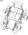
- Fig. 1 shows a mobile medical device 1 with at least one motor-driven wheel 2.
- the mobile medical device 1 has four wheels 2, each of which is motor-driven by its own electric motor 3.
- a protective plate-like, foldable cover element 4 is arranged over the motor-driven wheel 2, which can be seen in the open position. In the closed position, that is to say in the folded-down position, the cover element 4 can act to repel dirt and additionally act as a cable deflector.
- Fig. 1 also shows the mobile medical device 1 with a lifting device 13 of the motor-driven wheels 2 and with four further wheels 12 that are not motor-driven.
- each motor-driven wheel 2 has a lifting device 13. This means that each motor-driven wheel 2 can be lifted individually from a floor surface. When a wheel is changed, the mobile medical device 1 is supported on the remaining motor-driven wheels 2 that are not raised on the ground. In this embodiment, not shown, no additional wheels 12 or, for example, supports are required.
- all motor-driven wheels 2 can be lifted from the ground surface by the lifting devices 13 at the same time.
- the mobile medical device 1 has a further, second set of wheels consisting of at least two non-motor-driven wheels 12 or supports on which the mobile medical device 1 can be supported on the floor surface.
- the raised motor-driven wheels 2 are consequently free and can be removed.
- the lifting device 13 it is designed such that the motor-driven wheels 2 to be replaced remain at an unchanged height relative to a chassis of the mobile medical device 1.
- a chassis to mean the entirety of all parts of a mobile device which are used to connect the structure of the mobile device to the roadway via the wheels 2, which in this case are motor-driven. The entire chassis can then be lifted from the ground surface with the aid of additional wheels 12 or supports.
- the mobile medical device 1 preferably has a second set of wheels, i.e. at least three further, non-motor-driven wheels 12, since these can ensure that the mobile medical device 1 is nonetheless in the event of a failure of the motor drive by the electric motors 3 of the motor-driven wheels 2 can be moved and these are therefore safety-relevant.
- the mobile medical device 1 has four motor-driven wheels 2 in the form of omnidirectional wheels 15, for example Mecanum wheels.
- omnidirectional wheels for example Mecanum wheels.
- Mecanum wheels the direction of rotation and the speed of each individual wheel are controlled separately. This offers the advantage of optimal maneuverability, especially in tight spaces, as is often the case in operating theaters.
- Fig. 2 shows the motor-driven wheel 2, the hub 9, the axle 14 and the electric motor 3 in an axial section.
- the electric motor 3 is located in the axle 14, which is therefore designed as a hollow axle or as a tube.
- the motor-driven wheel 2 is seated on a hub 9 associated with this motor-driven wheel 2, which hub is rotatably mounted on the axle 14. This can be done by wheel bearings, for example in the form of ball bearings.
- the electric motor 3 thus drives the hub 3, which transmits the torque to the motor-driven wheel 2, via a transmission and one or more drivers, for example by means of driver pins or other known means for implementing a driver.
- Fig. 3 shows a motor-driven wheel 2 in an external view.
- the motor-driven wheel 2 has a locking device 5 integrated concentrically in the motor-driven wheel 2, the locking device 5 having a handle element 5 that can be folded out on the front side.
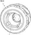
- Fig. 4 shows a motor-driven wheel 2, which is designed as an omnidirectional wheel 15, in an interior view or from its rear side, the rear side being the end face of the motor-driven wheel 2 facing the mobile medical device 1.
- the omnidirectional wheel 15 is designed as a mecanum wheel.
- a frusto-conical recess 8 is formed in the interior of the motor-driven wheel, i.e. the omnidirectional wheel 15, or in its inner circumference, this frustoconical recess 8 being designed to correspond and precisely fit the frustoconical design of the hub 9, as in Fig. 5 can be seen and is explained in more detail below.
- the locking device 5 can be seen, which has guide elements 6.
- the guide elements 6 can, for example, as in FIG Fig. 4 shown, be designed as pins.
- Fig. 5 shows a hub 9 belonging to the motor-driven wheel 2, which carries the motor-driven wheel 2 on its outer surface and is designed in the shape of a truncated cone in the present exemplary embodiment.
- Grooves 10 and anti-rotation elements 11 are formed on the circumference of the hub, which ensure that the motor-driven wheel 2 cannot rotate relative to the hub 9, either during operation or when locking.
- the motor-driven wheel 2 can be inserted and cleaned, for example, in a dishwashing or cleaning machine commonly used in clinical settings.
- the motor-driven wheel 2 can also be replaced immediately by a motor-driven wheel 2 that has already been cleaned.
- the locking device 5 is used to securely remove and fasten the motor-driven wheel 2, for example in the context of cleaning the motor-driven wheel 2.
- this is designed to be rotatable.
- helix-shaped grooves 10 are attached and at the same time attached to the corresponding counterpart, i.e. either on the rotatable locking device 5 or on the circumference of the hub 9, guide elements 7.
- the guide elements 7 cause When the locking device 5 is rotated, an axial displacement of the motor-driven wheel 2.
- the locking device 5 pushes and fixes the motor-driven wheel 2 on the hub 9 when it is rotated or detaches it from the hub 9 when it is rotated in the opposite direction.
- the locking and unlocking is implemented by locking elements, such as, for example, balls, which are pressed into the grooves 10 which are arranged on the circumference of the hub 9.
- the guide elements 7 are fixed in a detent position by an axially displaceable or rotatable sleeve on the motor-driven wheel 2 or in the hub 9.
- a centrally arranged foldable hook which pulls the motor-driven wheel 2 onto a sleeve described in the above paragraph and fixes it there, is locked.
- the centrally arranged foldable hook can be designed in such a way that it unlocks the motor-driven wheel 2 by actuation in the opposite direction and thus pushes it down from the hub 9.
- the grip element 6 can, for example, be designed as a handle and at the same time be designed to carry the wheel. This results in the advantage that the grip element 6 is sufficient on its own for releasing and carrying.
- the hub 5 can on its circumference with the at least one anti-rotation element 11, as in Fig. 5 can be seen to be equipped.
- An embodiment of the anti-rotation element 11 can be provided by an element protruding on the circumference of the hub 9, for example milled or screwed on, which can for example be octagonal formed.
- grooves are provided in the inner circumference of the motor-driven wheel 2, in which the anti-rotation elements 11 act. If an anti-rotation element 11 and grooves 10 are formed on the circumference of the hub 9 at the same time, these can each be attached to the different ends of the hub 9. For example, there are then on the outer, smaller - if the hub 9 is frustoconical, circumference of the hub 9, that is, the side facing away from the mobile medical device 1, the grooves 10 and on the opposite side, that is, on the outer, larger circumference - if the The hub 9 is frustoconical, that is to say the anti-rotation elements 11 on the side facing away from the mobile medical device 1.
- the fold-out handle element 6 of the locking device 5 is used to actuate the locking device 5.
- the fold-out handle element 6 can be designed as a fold-out handle so that the unlocked and removed motor-driven wheel 2 can be carried directly on this handle element 6 without the hassle of reaching around. This results in a significant advantage, since the motor-driven wheel 2 can be removed with bare hands and entirely without additional aids, such as tools.
- the fold-out handle element 6 can be designed in such a way that it can only be folded into its starting position when the motor-driven wheel 2 is attached, when the locking device 5 is in its locked end position, i.e. with the motor-driven wheel 2 firmly mounted Cams on the locking device 5 and corresponding depressions on the hub 9 can be achieved in the locking position. This also has a safety-relevant effect itself, since an inadvertently incomplete locking of the motor-driven wheel 2 is immediately visible.
- the cover element 4 of the motor-driven wheel 2 can, for example, when changing a wheel, folded over, i.e. be opened. In one embodiment, however, the cover element 4 can only be folded back into the starting position, i.e. closed position, if the motor-driven wheel 2 has been pushed completely to the correct axial position of the hub 9 and the grip element 7 of the locking device 5 has been folded in.
Landscapes
- Engineering & Computer Science (AREA)
- Mechanical Engineering (AREA)
- Health & Medical Sciences (AREA)
- Life Sciences & Earth Sciences (AREA)
- Veterinary Medicine (AREA)
- Animal Behavior & Ethology (AREA)
- Public Health (AREA)
- General Health & Medical Sciences (AREA)
- Nursing (AREA)
- Transportation (AREA)
- Combustion & Propulsion (AREA)
- Chemical & Material Sciences (AREA)
- Biomedical Technology (AREA)
- Medical Informatics (AREA)
- Apparatus For Radiation Diagnosis (AREA)
- Accommodation For Nursing Or Treatment Tables (AREA)
- Nuclear Medicine, Radiotherapy & Molecular Imaging (AREA)
- Radiology & Medical Imaging (AREA)
- Pathology (AREA)
- Optics & Photonics (AREA)
- Molecular Biology (AREA)
- High Energy & Nuclear Physics (AREA)
- Biophysics (AREA)
- Physics & Mathematics (AREA)
- Heart & Thoracic Surgery (AREA)
- Surgery (AREA)
- Arrangement Or Mounting Of Propulsion Units For Vehicles (AREA)
- Invalid Beds And Related Equipment (AREA)
- Dental Tools And Instruments Or Auxiliary Dental Instruments (AREA)
Applications Claiming Priority (2)
| Application Number | Priority Date | Filing Date | Title |
|---|---|---|---|
| DE102015206909.5A DE102015206909A1 (de) | 2015-04-16 | 2015-04-16 | Mobiles medizinisches Gerät mit mindestens einem motorisch angetriebenen Rad |
| PCT/EP2016/056515 WO2016165925A1 (de) | 2015-04-16 | 2016-03-24 | Mobiles medizinisches gerät mit mindestens einem motorisch angetriebenen rad |
Publications (2)
| Publication Number | Publication Date |
|---|---|
| EP3242802A1 EP3242802A1 (de) | 2017-11-15 |
| EP3242802B1 true EP3242802B1 (de) | 2020-08-19 |
Family
ID=55661388
Family Applications (1)
| Application Number | Title | Priority Date | Filing Date |
|---|---|---|---|
| EP16714334.6A Active EP3242802B1 (de) | 2015-04-16 | 2016-03-24 | Mobiles medizinisches gerät mit mindestens einem motorisch angetriebenen rad |
Country Status (6)
| Country | Link |
|---|---|
| US (1) | US11001098B2 (enExample) |
| EP (1) | EP3242802B1 (enExample) |
| JP (1) | JP6761812B2 (enExample) |
| CN (1) | CN107567317A (enExample) |
| DE (1) | DE102015206909A1 (enExample) |
| WO (1) | WO2016165925A1 (enExample) |
Families Citing this family (9)
| Publication number | Priority date | Publication date | Assignee | Title |
|---|---|---|---|---|
| US11058378B2 (en) * | 2016-02-03 | 2021-07-13 | Globus Medical, Inc. | Portable medical imaging system |
| JP2018131068A (ja) * | 2017-02-15 | 2018-08-23 | ナブテスコ株式会社 | 運搬台車用の駆動装置 |
| US11039964B2 (en) * | 2017-03-06 | 2021-06-22 | Stryker Corporation | Systems and methods for facilitating movement of a patient transport apparatus |
| CN206623628U (zh) * | 2017-04-07 | 2017-11-10 | 深圳市大疆创新科技有限公司 | 轮组装置及移动装置 |
| GB2566017B (en) * | 2017-08-29 | 2020-06-17 | Q Bot Ltd | Robotic vehicle |
| DE102018211669B4 (de) * | 2018-07-12 | 2020-01-23 | Siemens Healthcare Gmbh | Omnidirektionales Fahrwerk für eine Gantry eines Computertomographiegeräts |
| US11690582B2 (en) | 2020-05-06 | 2023-07-04 | GE Precision Healthcare LLC | Systems and methods for a mobile medical device drive platform |
| WO2022048611A1 (en) * | 2020-09-02 | 2022-03-10 | Shanghai United Imaging Healthcare Co., Ltd. | Mobile medical device |
| US12285970B2 (en) * | 2021-10-27 | 2025-04-29 | IW Technologies, LLC | Universal spinner wheel |
Citations (1)
| Publication number | Priority date | Publication date | Assignee | Title |
|---|---|---|---|---|
| DE19949408C1 (de) * | 1999-10-13 | 2000-10-12 | Alber Ulrich Gmbh & Co Kg | Fahrzeug, insbesondere Rollstuhl |
Family Cites Families (29)
| Publication number | Priority date | Publication date | Assignee | Title |
|---|---|---|---|---|
| US2026586A (en) * | 1934-03-31 | 1936-01-07 | Thomas C Mcveagh | Securing device |
| JPS4426357Y1 (enExample) * | 1965-10-22 | 1969-11-05 | ||
| JPS4612813Y1 (enExample) * | 1967-03-30 | 1971-05-07 | ||
| US3944285A (en) * | 1973-05-23 | 1976-03-16 | Gerald Vincent | Wheel safety lock |
| US4347907A (en) * | 1978-09-11 | 1982-09-07 | Downing Jr James H | All-electric A.C. tractor |
| GB2169055B (en) * | 1984-12-22 | 1988-08-17 | Unisys Corp | Improved hub assembly |
| JP3009470U (ja) * | 1994-09-26 | 1995-04-04 | 株式会社澤村製作所 | 2部材の連結構造 |
| KR20010052261A (ko) * | 1998-04-17 | 2001-06-25 | 트랙트-에이-필라 트랙터 컴패니 인코포레이티드 | 육상용 차량 |
| US6173481B1 (en) * | 1998-06-23 | 2001-01-16 | Michael B. Parent | Wheel removal and reassembly apparatus for brake access on heavy vehicles |
| JP2002046670A (ja) * | 2000-08-02 | 2002-02-12 | Yanmar Agricult Equip Co Ltd | 六輪作業車 |
| US6813939B1 (en) * | 2002-06-24 | 2004-11-09 | Laray A. Wilcoxon | Vehicle repair ramps with integral rolling system |
| US6802570B2 (en) * | 2002-09-27 | 2004-10-12 | Load Rite Trailers, Inc. | Oriented roller bushing for boat trailer |
| JP2004176874A (ja) * | 2002-11-29 | 2004-06-24 | Yamada Kogyo Kk | 連結装置 |
| GB2400084A (en) * | 2003-03-31 | 2004-10-06 | Karbon Kinetics Ltd | Bicycle hub assembly |
| JP3820239B2 (ja) * | 2003-08-22 | 2006-09-13 | 英希 根本 | 全方向移動用車輪およびこれに使用されるフレキシブルタイヤ |
| WO2006037935A1 (en) * | 2004-10-07 | 2006-04-13 | Ferno Uk Limited | Stretchers |
| US20080169140A1 (en) * | 2007-01-16 | 2008-07-17 | Charles Hampton Perry | Machine for augmentation, storage, and conservation of vehicle motive energy |
| CN201287583Y (zh) * | 2008-10-23 | 2009-08-12 | 东北大学 | 轮式机器人新型驱动轮 |
| CN201494299U (zh) * | 2009-09-07 | 2010-06-02 | 东南大学 | 电机减速器一体化麦克纳姆轮 |
| US8840304B2 (en) * | 2010-06-14 | 2014-09-23 | General Electric Company | Positioner for ultra-portable imaging system |
| US8549705B1 (en) * | 2012-07-12 | 2013-10-08 | Chen-Chuan Wu | Hollow wheel set |
| US9320962B2 (en) * | 2012-08-21 | 2016-04-26 | Brian J. Krell | Apparatus and methods for quickly releasing a hub-and-wheel assembly |
| KR20150000171A (ko) | 2013-06-24 | 2015-01-02 | 삼성전자주식회사 | 이동 가능한 의료 장비 및 의료 장비의 이동 제어 방법 |
| CN203226834U (zh) | 2013-07-16 | 2013-10-09 | 王兴松 | 一种可全方位移动的c臂x光机 |
| CN203698407U (zh) * | 2013-11-12 | 2014-07-09 | 刘新广 | 万向电动车 |
| US20150223890A1 (en) * | 2014-02-07 | 2015-08-13 | Enovate Medical,Llc | Medical Cart Application Distribution |
| US20150223891A1 (en) * | 2014-02-07 | 2015-08-13 | Enovate Medical Llc | Medical cart access control |
| CN204172612U (zh) * | 2014-08-21 | 2015-02-25 | 黄利明 | 婴儿车车轮 |
| GB2539627A (en) * | 2015-04-22 | 2016-12-28 | I-Glider Ltd | A reconfigurable wheeled personal mobility device |
-
2015
- 2015-04-16 DE DE102015206909.5A patent/DE102015206909A1/de not_active Ceased
-
2016
- 2016-03-24 WO PCT/EP2016/056515 patent/WO2016165925A1/de not_active Ceased
- 2016-03-24 US US15/566,477 patent/US11001098B2/en not_active Expired - Fee Related
- 2016-03-24 CN CN201680022264.4A patent/CN107567317A/zh active Pending
- 2016-03-24 JP JP2017554044A patent/JP6761812B2/ja not_active Expired - Fee Related
- 2016-03-24 EP EP16714334.6A patent/EP3242802B1/de active Active
Patent Citations (1)
| Publication number | Priority date | Publication date | Assignee | Title |
|---|---|---|---|---|
| DE19949408C1 (de) * | 1999-10-13 | 2000-10-12 | Alber Ulrich Gmbh & Co Kg | Fahrzeug, insbesondere Rollstuhl |
Also Published As
| Publication number | Publication date |
|---|---|
| CN107567317A (zh) | 2018-01-09 |
| JP2018516796A (ja) | 2018-06-28 |
| EP3242802A1 (de) | 2017-11-15 |
| DE102015206909A1 (de) | 2016-10-20 |
| JP6761812B2 (ja) | 2020-09-30 |
| US11001098B2 (en) | 2021-05-11 |
| US20180297396A1 (en) | 2018-10-18 |
| WO2016165925A1 (de) | 2016-10-20 |
Similar Documents
| Publication | Publication Date | Title |
|---|---|---|
| EP3242802B1 (de) | Mobiles medizinisches gerät mit mindestens einem motorisch angetriebenen rad | |
| DE60309224T2 (de) | Reifenabdrückvorrichtung und Reifendemontiereinheit für eine Reifenwechselmaschine | |
| DE102016225297A1 (de) | Lenkrad für eine Kraftfahrzeuglenkung und Lenksäule für ein Kraftfahrzeug | |
| DE102016115466A1 (de) | Steuerhorn für die Lenkung eines Kraftfahrzeugs | |
| DE102021203496A1 (de) | Klappbare lenkradanordnung und lenkvorrichtung, die diese umfasst | |
| DE102016118032A1 (de) | Antriebseinheit und Rollstuhl mit Antriebseinheit | |
| WO2015169556A1 (de) | Lenkwelle für eine kraftfahrzeuglenkung | |
| WO2018036703A1 (de) | Lenkrad zum betätigen einer lenkbewegung eines fahrzeuges | |
| DE102015221720A1 (de) | Verfahren und Vorrichtung zum Betreiben eines Kraftfahrzeugs, Kraftfahrzeug | |
| EP3072778B1 (de) | Lenkradbetätigungsvorrichtung | |
| DE202014007664U1 (de) | Umkonfigurierbares Lenkrad | |
| DE602005000235T2 (de) | Vorrichtung zum Montieren und Demontieren von Rädern | |
| EP3170722B1 (de) | Verfahren und vorrichtung zur montage eines fahrzeugs, insbesondere eines nutzfahrzeugs | |
| EP3350017B1 (de) | Kopfstütze für einen fahrzeugsitz und system zur bildung einer in eine kopfstütze integrierbaren ausrichtungsvorrichtung | |
| DE102013210537A1 (de) | Mobile Patientenliege | |
| DE102021213561B4 (de) | Transformationsrad und Robotersystem | |
| EP1092407B1 (de) | Fahrzeug, insbesondere Rollstuhl | |
| DE102015004817A1 (de) | Lenkvorrichtung für ein Fahrzeug | |
| EP3684316B1 (de) | Antriebsvorrichtung für einen rollstuhl | |
| DE3505325A1 (de) | Einrichtung zum reibungsfreien kuppeln, welche ein wahlweises abkuppeln einer abtriebswelle von einer antriebswelle erlaubt und gleichzeitig wenigstens eine bremsung der abgekuppelten abtriebswelle bewirkt, mit derartigen einrichtungen versehene motor-achsanordnung und mit einer derartigen achsanordnung versehenes einachsiges motorfahrzeug | |
| DE102009019602B3 (de) | Bewegungseinrichtung für ein Karosserieteil | |
| DE102015117681A1 (de) | Bremse mit einer Notlüfteinrichtung | |
| WO2014127967A1 (de) | Haltevorrichtung für ein chirurgisches instrument und eine schleuse mit notlösefunktion | |
| DE102015113156B4 (de) | Aktiver Radträger für ein Fahrzeug und Fahrwerk für ein Kraftfahrzeug sowie Fahrzeug | |
| DE102006032842B4 (de) | Zusatzantreibsvorrichtung für manuelle Rollstühle |
Legal Events
| Date | Code | Title | Description |
|---|---|---|---|
| STAA | Information on the status of an ep patent application or granted ep patent |
Free format text: STATUS: THE INTERNATIONAL PUBLICATION HAS BEEN MADE |
|
| PUAI | Public reference made under article 153(3) epc to a published international application that has entered the european phase |
Free format text: ORIGINAL CODE: 0009012 |
|
| STAA | Information on the status of an ep patent application or granted ep patent |
Free format text: STATUS: REQUEST FOR EXAMINATION WAS MADE |
|
| 17P | Request for examination filed |
Effective date: 20170810 |
|
| AK | Designated contracting states |
Kind code of ref document: A1 Designated state(s): AL AT BE BG CH CY CZ DE DK EE ES FI FR GB GR HR HU IE IS IT LI LT LU LV MC MK MT NL NO PL PT RO RS SE SI SK SM TR |
|
| AX | Request for extension of the european patent |
Extension state: BA ME |
|
| DAV | Request for validation of the european patent (deleted) | ||
| DAX | Request for extension of the european patent (deleted) | ||
| STAA | Information on the status of an ep patent application or granted ep patent |
Free format text: STATUS: EXAMINATION IS IN PROGRESS |
|
| 17Q | First examination report despatched |
Effective date: 20190322 |
|
| GRAP | Despatch of communication of intention to grant a patent |
Free format text: ORIGINAL CODE: EPIDOSNIGR1 |
|
| STAA | Information on the status of an ep patent application or granted ep patent |
Free format text: STATUS: GRANT OF PATENT IS INTENDED |
|
| GRAJ | Information related to disapproval of communication of intention to grant by the applicant or resumption of examination proceedings by the epo deleted |
Free format text: ORIGINAL CODE: EPIDOSDIGR1 |
|
| STAA | Information on the status of an ep patent application or granted ep patent |
Free format text: STATUS: EXAMINATION IS IN PROGRESS |
|
| INTG | Intention to grant announced |
Effective date: 20200127 |
|
| INTC | Intention to grant announced (deleted) | ||
| GRAP | Despatch of communication of intention to grant a patent |
Free format text: ORIGINAL CODE: EPIDOSNIGR1 |
|
| STAA | Information on the status of an ep patent application or granted ep patent |
Free format text: STATUS: GRANT OF PATENT IS INTENDED |
|
| INTG | Intention to grant announced |
Effective date: 20200409 |
|
| GRAS | Grant fee paid |
Free format text: ORIGINAL CODE: EPIDOSNIGR3 |
|
| GRAA | (expected) grant |
Free format text: ORIGINAL CODE: 0009210 |
|
| STAA | Information on the status of an ep patent application or granted ep patent |
Free format text: STATUS: THE PATENT HAS BEEN GRANTED |
|
| AK | Designated contracting states |
Kind code of ref document: B1 Designated state(s): AL AT BE BG CH CY CZ DE DK EE ES FI FR GB GR HR HU IE IS IT LI LT LU LV MC MK MT NL NO PL PT RO RS SE SI SK SM TR |
|
| REG | Reference to a national code |
Ref country code: CH Ref legal event code: EP |
|
| REG | Reference to a national code |
Ref country code: DE Ref legal event code: R096 Ref document number: 502016010893 Country of ref document: DE |
|
| REG | Reference to a national code |
Ref country code: AT Ref legal event code: REF Ref document number: 1303527 Country of ref document: AT Kind code of ref document: T Effective date: 20200915 |
|
| REG | Reference to a national code |
Ref country code: IE Ref legal event code: FG4D Free format text: LANGUAGE OF EP DOCUMENT: GERMAN |
|
| REG | Reference to a national code |
Ref country code: LT Ref legal event code: MG4D |
|
| REG | Reference to a national code |
Ref country code: NL Ref legal event code: MP Effective date: 20200819 |
|
| PG25 | Lapsed in a contracting state [announced via postgrant information from national office to epo] |
Ref country code: PT Free format text: LAPSE BECAUSE OF FAILURE TO SUBMIT A TRANSLATION OF THE DESCRIPTION OR TO PAY THE FEE WITHIN THE PRESCRIBED TIME-LIMIT Effective date: 20201221 Ref country code: FI Free format text: LAPSE BECAUSE OF FAILURE TO SUBMIT A TRANSLATION OF THE DESCRIPTION OR TO PAY THE FEE WITHIN THE PRESCRIBED TIME-LIMIT Effective date: 20200819 Ref country code: BG Free format text: LAPSE BECAUSE OF FAILURE TO SUBMIT A TRANSLATION OF THE DESCRIPTION OR TO PAY THE FEE WITHIN THE PRESCRIBED TIME-LIMIT Effective date: 20201119 Ref country code: NO Free format text: LAPSE BECAUSE OF FAILURE TO SUBMIT A TRANSLATION OF THE DESCRIPTION OR TO PAY THE FEE WITHIN THE PRESCRIBED TIME-LIMIT Effective date: 20201119 Ref country code: SE Free format text: LAPSE BECAUSE OF FAILURE TO SUBMIT A TRANSLATION OF THE DESCRIPTION OR TO PAY THE FEE WITHIN THE PRESCRIBED TIME-LIMIT Effective date: 20200819 Ref country code: HR Free format text: LAPSE BECAUSE OF FAILURE TO SUBMIT A TRANSLATION OF THE DESCRIPTION OR TO PAY THE FEE WITHIN THE PRESCRIBED TIME-LIMIT Effective date: 20200819 Ref country code: LT Free format text: LAPSE BECAUSE OF FAILURE TO SUBMIT A TRANSLATION OF THE DESCRIPTION OR TO PAY THE FEE WITHIN THE PRESCRIBED TIME-LIMIT Effective date: 20200819 Ref country code: GR Free format text: LAPSE BECAUSE OF FAILURE TO SUBMIT A TRANSLATION OF THE DESCRIPTION OR TO PAY THE FEE WITHIN THE PRESCRIBED TIME-LIMIT Effective date: 20201120 |
|
| PG25 | Lapsed in a contracting state [announced via postgrant information from national office to epo] |
Ref country code: PL Free format text: LAPSE BECAUSE OF FAILURE TO SUBMIT A TRANSLATION OF THE DESCRIPTION OR TO PAY THE FEE WITHIN THE PRESCRIBED TIME-LIMIT Effective date: 20200819 Ref country code: NL Free format text: LAPSE BECAUSE OF FAILURE TO SUBMIT A TRANSLATION OF THE DESCRIPTION OR TO PAY THE FEE WITHIN THE PRESCRIBED TIME-LIMIT Effective date: 20200819 Ref country code: LV Free format text: LAPSE BECAUSE OF FAILURE TO SUBMIT A TRANSLATION OF THE DESCRIPTION OR TO PAY THE FEE WITHIN THE PRESCRIBED TIME-LIMIT Effective date: 20200819 Ref country code: RS Free format text: LAPSE BECAUSE OF FAILURE TO SUBMIT A TRANSLATION OF THE DESCRIPTION OR TO PAY THE FEE WITHIN THE PRESCRIBED TIME-LIMIT Effective date: 20200819 Ref country code: IS Free format text: LAPSE BECAUSE OF FAILURE TO SUBMIT A TRANSLATION OF THE DESCRIPTION OR TO PAY THE FEE WITHIN THE PRESCRIBED TIME-LIMIT Effective date: 20201219 |
|
| PG25 | Lapsed in a contracting state [announced via postgrant information from national office to epo] |
Ref country code: EE Free format text: LAPSE BECAUSE OF FAILURE TO SUBMIT A TRANSLATION OF THE DESCRIPTION OR TO PAY THE FEE WITHIN THE PRESCRIBED TIME-LIMIT Effective date: 20200819 Ref country code: RO Free format text: LAPSE BECAUSE OF FAILURE TO SUBMIT A TRANSLATION OF THE DESCRIPTION OR TO PAY THE FEE WITHIN THE PRESCRIBED TIME-LIMIT Effective date: 20200819 Ref country code: SM Free format text: LAPSE BECAUSE OF FAILURE TO SUBMIT A TRANSLATION OF THE DESCRIPTION OR TO PAY THE FEE WITHIN THE PRESCRIBED TIME-LIMIT Effective date: 20200819 Ref country code: CZ Free format text: LAPSE BECAUSE OF FAILURE TO SUBMIT A TRANSLATION OF THE DESCRIPTION OR TO PAY THE FEE WITHIN THE PRESCRIBED TIME-LIMIT Effective date: 20200819 Ref country code: DK Free format text: LAPSE BECAUSE OF FAILURE TO SUBMIT A TRANSLATION OF THE DESCRIPTION OR TO PAY THE FEE WITHIN THE PRESCRIBED TIME-LIMIT Effective date: 20200819 |
|
| REG | Reference to a national code |
Ref country code: DE Ref legal event code: R097 Ref document number: 502016010893 Country of ref document: DE |
|
| PG25 | Lapsed in a contracting state [announced via postgrant information from national office to epo] |
Ref country code: AL Free format text: LAPSE BECAUSE OF FAILURE TO SUBMIT A TRANSLATION OF THE DESCRIPTION OR TO PAY THE FEE WITHIN THE PRESCRIBED TIME-LIMIT Effective date: 20200819 Ref country code: ES Free format text: LAPSE BECAUSE OF FAILURE TO SUBMIT A TRANSLATION OF THE DESCRIPTION OR TO PAY THE FEE WITHIN THE PRESCRIBED TIME-LIMIT Effective date: 20200819 |
|
| PLBE | No opposition filed within time limit |
Free format text: ORIGINAL CODE: 0009261 |
|
| STAA | Information on the status of an ep patent application or granted ep patent |
Free format text: STATUS: NO OPPOSITION FILED WITHIN TIME LIMIT |
|
| PG25 | Lapsed in a contracting state [announced via postgrant information from national office to epo] |
Ref country code: SK Free format text: LAPSE BECAUSE OF FAILURE TO SUBMIT A TRANSLATION OF THE DESCRIPTION OR TO PAY THE FEE WITHIN THE PRESCRIBED TIME-LIMIT Effective date: 20200819 |
|
| 26N | No opposition filed |
Effective date: 20210520 |
|
| PG25 | Lapsed in a contracting state [announced via postgrant information from national office to epo] |
Ref country code: IT Free format text: LAPSE BECAUSE OF FAILURE TO SUBMIT A TRANSLATION OF THE DESCRIPTION OR TO PAY THE FEE WITHIN THE PRESCRIBED TIME-LIMIT Effective date: 20200819 |
|
| PG25 | Lapsed in a contracting state [announced via postgrant information from national office to epo] |
Ref country code: SI Free format text: LAPSE BECAUSE OF FAILURE TO SUBMIT A TRANSLATION OF THE DESCRIPTION OR TO PAY THE FEE WITHIN THE PRESCRIBED TIME-LIMIT Effective date: 20200819 |
|
| PG25 | Lapsed in a contracting state [announced via postgrant information from national office to epo] |
Ref country code: MC Free format text: LAPSE BECAUSE OF FAILURE TO SUBMIT A TRANSLATION OF THE DESCRIPTION OR TO PAY THE FEE WITHIN THE PRESCRIBED TIME-LIMIT Effective date: 20200819 |
|
| REG | Reference to a national code |
Ref country code: CH Ref legal event code: PL |
|
| REG | Reference to a national code |
Ref country code: BE Ref legal event code: MM Effective date: 20210331 |
|
| PG25 | Lapsed in a contracting state [announced via postgrant information from national office to epo] |
Ref country code: IE Free format text: LAPSE BECAUSE OF NON-PAYMENT OF DUE FEES Effective date: 20210324 Ref country code: LI Free format text: LAPSE BECAUSE OF NON-PAYMENT OF DUE FEES Effective date: 20210331 Ref country code: LU Free format text: LAPSE BECAUSE OF NON-PAYMENT OF DUE FEES Effective date: 20210324 Ref country code: CH Free format text: LAPSE BECAUSE OF NON-PAYMENT OF DUE FEES Effective date: 20210331 |
|
| REG | Reference to a national code |
Ref country code: AT Ref legal event code: MM01 Ref document number: 1303527 Country of ref document: AT Kind code of ref document: T Effective date: 20210324 |
|
| PG25 | Lapsed in a contracting state [announced via postgrant information from national office to epo] |
Ref country code: BE Free format text: LAPSE BECAUSE OF NON-PAYMENT OF DUE FEES Effective date: 20210331 |
|
| PG25 | Lapsed in a contracting state [announced via postgrant information from national office to epo] |
Ref country code: AT Free format text: LAPSE BECAUSE OF NON-PAYMENT OF DUE FEES Effective date: 20210324 |
|
| PG25 | Lapsed in a contracting state [announced via postgrant information from national office to epo] |
Ref country code: HU Free format text: LAPSE BECAUSE OF FAILURE TO SUBMIT A TRANSLATION OF THE DESCRIPTION OR TO PAY THE FEE WITHIN THE PRESCRIBED TIME-LIMIT; INVALID AB INITIO Effective date: 20160324 |
|
| PG25 | Lapsed in a contracting state [announced via postgrant information from national office to epo] |
Ref country code: CY Free format text: LAPSE BECAUSE OF FAILURE TO SUBMIT A TRANSLATION OF THE DESCRIPTION OR TO PAY THE FEE WITHIN THE PRESCRIBED TIME-LIMIT Effective date: 20200819 |
|
| REG | Reference to a national code |
Ref country code: DE Ref legal event code: R081 Ref document number: 502016010893 Country of ref document: DE Owner name: SIEMENS HEALTHINEERS AG, DE Free format text: FORMER OWNER: SIEMENS HEALTHCARE GMBH, MUENCHEN, DE |
|
| PG25 | Lapsed in a contracting state [announced via postgrant information from national office to epo] |
Ref country code: MK Free format text: LAPSE BECAUSE OF FAILURE TO SUBMIT A TRANSLATION OF THE DESCRIPTION OR TO PAY THE FEE WITHIN THE PRESCRIBED TIME-LIMIT Effective date: 20200819 |
|
| PGFP | Annual fee paid to national office [announced via postgrant information from national office to epo] |
Ref country code: FR Payment date: 20240319 Year of fee payment: 9 |
|
| PG25 | Lapsed in a contracting state [announced via postgrant information from national office to epo] |
Ref country code: TR Free format text: LAPSE BECAUSE OF FAILURE TO SUBMIT A TRANSLATION OF THE DESCRIPTION OR TO PAY THE FEE WITHIN THE PRESCRIBED TIME-LIMIT Effective date: 20200819 |
|
| PGFP | Annual fee paid to national office [announced via postgrant information from national office to epo] |
Ref country code: GB Payment date: 20240409 Year of fee payment: 9 |
|
| PGFP | Annual fee paid to national office [announced via postgrant information from national office to epo] |
Ref country code: DE Payment date: 20240517 Year of fee payment: 9 |
|
| PG25 | Lapsed in a contracting state [announced via postgrant information from national office to epo] |
Ref country code: MT Free format text: LAPSE BECAUSE OF FAILURE TO SUBMIT A TRANSLATION OF THE DESCRIPTION OR TO PAY THE FEE WITHIN THE PRESCRIBED TIME-LIMIT Effective date: 20200819 |
|
| REG | Reference to a national code |
Ref country code: DE Ref legal event code: R119 Ref document number: 502016010893 Country of ref document: DE |
|
| GBPC | Gb: european patent ceased through non-payment of renewal fee |
Effective date: 20250324 |