EP3241773A1 - Metal bottle can - Google Patents
Metal bottle can Download PDFInfo
- Publication number
- EP3241773A1 EP3241773A1 EP17175294.2A EP17175294A EP3241773A1 EP 3241773 A1 EP3241773 A1 EP 3241773A1 EP 17175294 A EP17175294 A EP 17175294A EP 3241773 A1 EP3241773 A1 EP 3241773A1
- Authority
- EP
- European Patent Office
- Prior art keywords
- metal bottle
- wall thickness
- mouth
- neck
- barrel
- Prior art date
- Legal status (The legal status is an assumption and is not a legal conclusion. Google has not performed a legal analysis and makes no representation as to the accuracy of the status listed.)
- Withdrawn
Links
Images


Classifications
-
- B—PERFORMING OPERATIONS; TRANSPORTING
- B65—CONVEYING; PACKING; STORING; HANDLING THIN OR FILAMENTARY MATERIAL
- B65D—CONTAINERS FOR STORAGE OR TRANSPORT OF ARTICLES OR MATERIALS, e.g. BAGS, BARRELS, BOTTLES, BOXES, CANS, CARTONS, CRATES, DRUMS, JARS, TANKS, HOPPERS, FORWARDING CONTAINERS; ACCESSORIES, CLOSURES, OR FITTINGS THEREFOR; PACKAGING ELEMENTS; PACKAGES
- B65D1/00—Rigid or semi-rigid containers having bodies formed in one piece, e.g. by casting metallic material, by moulding plastics, by blowing vitreous material, by throwing ceramic material, by moulding pulped fibrous material or by deep-drawing operations performed on sheet material
- B65D1/02—Bottles or similar containers with necks or like restricted apertures, designed for pouring contents
- B65D1/0207—Bottles or similar containers with necks or like restricted apertures, designed for pouring contents characterised by material, e.g. composition, physical features
-
- B—PERFORMING OPERATIONS; TRANSPORTING
- B65—CONVEYING; PACKING; STORING; HANDLING THIN OR FILAMENTARY MATERIAL
- B65D—CONTAINERS FOR STORAGE OR TRANSPORT OF ARTICLES OR MATERIALS, e.g. BAGS, BARRELS, BOTTLES, BOXES, CANS, CARTONS, CRATES, DRUMS, JARS, TANKS, HOPPERS, FORWARDING CONTAINERS; ACCESSORIES, CLOSURES, OR FITTINGS THEREFOR; PACKAGING ELEMENTS; PACKAGES
- B65D1/00—Rigid or semi-rigid containers having bodies formed in one piece, e.g. by casting metallic material, by moulding plastics, by blowing vitreous material, by throwing ceramic material, by moulding pulped fibrous material or by deep-drawing operations performed on sheet material
- B65D1/02—Bottles or similar containers with necks or like restricted apertures, designed for pouring contents
- B65D1/0223—Bottles or similar containers with necks or like restricted apertures, designed for pouring contents characterised by shape
- B65D1/023—Neck construction
- B65D1/0246—Closure retaining means, e.g. beads, screw-threads
Definitions
- This invention relates to a metal bottle can in which an easily openable cap is wound and fastened to a mouth part, or a cap is screwed to a male screw portion of the mouth part.
- a metal bottle can for easy holding, in which the balance of thinning and weight reduction are attained while maintaining the necessary strength.
- various metal bottle cans in which beer, refreshing liquid etc. is filled are produced and sold in the market, and are used by general consumers.
- a plate member of aluminum alloy for example, a primitive plate of the thickness 0.5 mm or more of plate material 3104-H19 etc. is used.
- the mouth part, shoulder part, barrel part, and bottom part are integrally formed by drawing processing, necking processing.
- An easily openable cap opened by pulling a pull tab is wound and fastened to the mouth part of the metal bottle can, or a screw cap which is capable of resealing the mouth part after taking off the seal, is screwed to the mouth part of the meal bottle can for protecting contents.
- Conventional metal bottle cans have inadequacy of generating buckling in the neck part, the shoulder part or the barrel part, caused by a downward load applied along the can axis, and generating deformation in the mouth part caused by a load applied in the direction of crushing a curl portion.
- the loads are applied when forming the curl portion in the mouth part of the metal bottle can, when winding and fastening an easily openable cap, or when capping a screw cap.
- conventional metal bottle cans having the mouth part, shoulder part, or barrel part of which the wall thickness is thick wholly have been manufactured using a thick primitive plate material. In case when the thin primitive plate material is used from the very beginning, the strength of the mouth part, shoulder part, or barrel part will be inadequate.
- Patent Document 1 is known.
- Patent Document 1 Published Japanese Patent Application No. S56-183155 .
- a metal bottle can in which the thickness is thinned has been proactively investigated.
- the thinning of each part of a metal bottle can in a single uniform way for the purpose of cost down may causes the lowering of the strength of the metal bottle can, and may leads the fault forming of curl of the mouth part and the male screw portion. It is apparent that unconsidered thinning will cause the deterioration of quality of the metal bottle cans.
- metal bottle cans attaining cost down are demanded in which the necessary portions have strength with a proper wall thickness, and in which the unnecessary portion is thinned, presuming reasonable metal bottle cans.
- the present invention is devised focusing attention on such problems, and is directed to provide a thinned reasonable metal bottle can having a sufficient strength to withstand a load applied when forming a curl portion, a load applied when winding and fastening an easily openable cap, or a load applied when capping a screw cap. More specifically, the present invention is to provide a metal bottle cap in which the mouth part, the neck part, or the barrel part maintains a sufficient strength not to generate deformation, buckling in the manufacturing process or in the filling process of contents, and to provide a metal bottle can being not deformed, being not depressed in each stage of transportation, sale, or consumption as a product, and being easy to hold and easy to handle, while attaining the balance of thinning and weight reduction.
- the present invention of claim 1 is a metal bottle can which comprises a mouth part having a curl portion at an end, a neck part having a straight portion in parallel to a can axis, a shoulder part having a tapered shape, a barrel part, and a bottom part.
- the diameter A of the barrel part is 40 mm to 70 mm
- a diameter B of the neck part is 20 mm to 35 mm
- a length S of the straight portion of the neck part is 10 mm to 40 mm
- an angle ⁇ of the shoulder part is 40 degree to 70 degree
- a wall thickness X of the mouth part is 0.46 mm to 0.33mm
- a wall thickness Y of the straight portion of the neck part is 0.43mm to 0.30mm.
- the metal bottle can is integrally formed by drawing a primitive plate of thickness (wall thickness T) of 0.48 mm to 0.30 mm.
- the claim 2 of the present invention is a metal bottle can, in which a wall thickness Z of the shoulder part is 0.22 mm to 0.12 mm and a wall thickness W of the barrel part is 0.22 mm to 0.12 mm.
- the claim 3 of the present invention is a metal bottle can, in which the wall thickness X' of the curl portion is 0.48 mm to 0.35 mm, the angle ⁇ between the straight line portion of the curl portion and a horizontal line is 0 ⁇ 25 degrees, the radius of a curvature R of the lower portion of the curl portion is 0.5 mm ⁇ R ⁇ 1.0 mm, or in which the wall thickness X' of the curl portion is 0.48 mm to 0.35 mm, the angle ⁇ ' between the straight line portion of the curl portion and the horizontal line is 0 ⁇ ⁇ ' ⁇ 25 degrees, the radius of the curvature R' of the lower portion of the curl portion is 0.5 ⁇ R ⁇ 1.0 mm.
- the claim 4 of the present invention is a metal bottle can, in which an easily openable cap is wound and fastened to the curl portion.
- the claim 5 of the present invention is a metal bottle can, in which the outer diameter C of a annular recessed portion of the mouth part is smaller than a diameter B of the straight portion of the neck part, so that a tongue piece which connects a top surface wall of an easily openable cap and a pull tab is placed along a wall surface of the annular recessed portion of the mouth portion of the metal bottle can.
- the claim 6 of the present invention is a metal bottle can, in which the diameter of the straight portion of the neck part is lengthened to the lower portion of the curl portion.
- the claim 7 of the present invention is a metal bottle can which comprises a mouth part having a curl portion at an end and a male screw portion formed at a periphery, a neck part having a straight portion in parallel to a can axis, a shoulder part having a tapered shape, a barrel part, and a bottom part.
- the diameter A of the barrel part is 40 mm to 70 mm
- an angle ⁇ of the shoulder part is 40 degree to 70 degree
- a wall thickness E of the mouth part is 0.45 mm to 0.32mm
- a wall thickness F of the straight portion of the neck part is 0.40mm to 0.30mm.
- the metal bottle can is integrally formed by drawing a primitive plate of thickness (wall thickness T) of 0.48 mm to 0.30 mm.
- the claim 8 of the present invention is a metal bottle can, in which the metal bottle can has a neck part which does not have a straight portion in parallel to the can axis.
- the claim 9 of the present invention is a metal bottle can, in which the wall thickness G of the shoulder part having the tapered shape is 0.33mm to 0.20mm, and the wall thickness H of the barrel part is 0.22mm to 0.12mm.
- the claim 10 of the present invention is a metal bottle can which comprises a mouth part having a curl portion at the end, a neck part having a tapered shape, a shoulder part having a tapered shape, a barrel part, and a bottom part.
- the diameter A of the barrel part is 40 mm to 70 mm
- an angle ⁇ of the shoulder part is 50 degree to 89 degree
- a wall thickness O of the mouth part is 0.46 mm to 0.33mm
- a wall thickness Y of the neck part having tapered shape is 0.43mm to 0.30mm.
- the metal bottle can is integrally formed by drawing a primitive plate of thickness (wall thickness T) of 0.48 mm to 0.30 mm.
- the claim 11 of the present invention is a metal bottle can in which the wall thickness Q of the shoulder part having tapered shape is 0.33mm to 0.20mm, and the wall thickness U of the barrel part is 0.22mm to 0.12mm.
- the metal bottle can of the present invention has an effect to have a sufficient strength to withstand a load applied when forming the curl portion, a load applied when winding and fastening the easily openable cap, or a load applied when capping the screw cap. And, it has an effect to be capable of providing a reasonable metal bottle can at a cheap cost, in which the balance of thinning and weight reduction is attained, while maintaining the strength. Further, it has an effect that it will not deform, or it will not depress in each stage of transportation, sale, or consumption as a product. Further, the metal bottle can of the present invention is easy to hold and easy to handle.
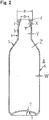
- a metal bottle can 8 of Figure 1 comprises a cylindrical barrel part 6, a bottom part 7 closing the lower end thereof, a taper-shaped shoulder part 5 formed in the upper end of the barrel part, a cylindrical neck part 4 formed in the upper end of the shoulder part, and a mouth part 1 formed in the upper end of the neck part through a taper portion 4a.
- a curl portion 2 is formed in the upper end of the mouth part.
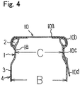
- the curl portion 2 is roughly circular in the shape thereof as shown in Figure 5 , 6 .
- the curled portion 2 has a diameter-contracted portion 2b where the diameter is contracted from the upper end of the mouth part, a standing-up portion 2c extending upward from the upper end of the diameter-contracted portion, an upper flexion portion 2d of the upper end of the standing-up portion, an outward protruded bend portion 2e expanding outward and extending downward smoothly from the upper flexion portion, a lower flexion portion 2f of the lower end of the bend portion, and a straight-line portion 2a extending straightly to the diameter- contracted portion from the lower flexion portion.
- the height L of the upper end (lower end of the shoulder part) of the barrel part from the upper end of the mouth part is 40 mm to 100 mm, preferably 50 mm to 86 mm ( Figure 1 ).
- the wall thickness T of the bottom part is 0.48 mm to 0.30 mm, preferably 0.44 mm to 0.35 mm ( Figure 2 ).
- the diameter A of the barrel part is 40 mm to 70 mm, preferably 45 mm to 66 mm ( Figure 1 ).
- the wall thickness W of the barrel part is 0.22 mm to 0.12 mm, preferably 0.19 mm to 0.12 mm ( Figure 2 ).
- the angle ⁇ of the shoulder part is 40 degrees to 70 degrees, preferably 55 degrees to 62 degrees ( Figure 1 ).
- the wall thickness Z of the shoulder part is 0.33 mm to 0.20 mm, preferably 0.30 mm to 0.20 mm ( Figure 2 ).
- the diameter B of the neck part is 10 mm to 40 mm, preferably 22 mm to 29 mm ( Figure 1 ).
- the wall thickness Y of the neck part is 0.43 mm to 0.30 mm, preferably 0.41 mm to 0.32 mm ( Figure 2 ).
- the height S of the neck part is 10 mm to 37 mm ( Figure 1 ).
- the diameter C of the mouth part is 17 mm to 24 mm, preferably 22 mm to 24 mm ( Figure 1 ).
- the wall thickness X of the mouth part is 0.46 mm to 0.33 mm, preferably 0.44 mm to 0.35 mm ( Figure 2 ).
- the wall thickness X' of the curl portion is 0.48 mm to 0.35 mm, preferably 0.47 mm to 0.37 mm ( Figure 5 ).
- the inner diameter D of the curl portion is 22 mm to 17 mm, preferably 20.5 mm to 18.5 mm ( Figure 2 ).
- the outer diameter E of the curl portion is 28 mm to 26 mm, preferably 26.4 mm to 26.2 mm ( Figure 2 ).
- the height I of the curl portion is 6.0 mm to 3.0mm, preferably 4.0 mm to 3.5 mm ( Figure 5 ).
- the width J of the curl portion is 5.0 mm to 2.0 mm, preferably 4.0 mm to 2.8 mm ( Figure 5 ).
- the diameter C of the mouth part/the diameter B of the neck part ⁇ 100 is 65 % to 100 %, preferably 80 % to 100 %.
- the angle ⁇ of the diameter-contracted portion is 25 degrees to 65 degrees, preferably 35 degrees to 50 degrees ( Figure 5 ).
- the curvature radius R1 of the upper flexion portion is 0.5 mm to 1.0 mm, preferably 0.6 mm to 0.9 mm ( Figure 5 ).
- the curvature radius R2 of the bend portion is 2.0 mm to 3.0 mm ( Figure 5 ).
- the curvature radius R3 of the lower flexion portion is 0.5 mm to 1.0 mm ( Figure 5 ).
- the angle ⁇ of the straight-line portion against a horizontal line is 0 degree to 25 degrees, preferably 0 degree to 5 degrees, the angle ⁇ ' is 0 degree to minus 25 degrees, preferably 0 degree to minus 5 degrees ( Figure 5 ).
- a metal bottle can 18 of Figure 7 comprises a cylindrical barrel part 16, a bottom part 17 closing the lower end thereof, a taper-shaped shoulder part 15 formed in the upper end of the barrel part, a cylindrical neck part 14 formed in the upper end of the shoulder part, and a mouth part 11 formed in the upper end of the neck part through a taper portion 14a.
- a curl portion 12 is formed in the upper end of the mouth part.
- a straight portion 13, a screw portion 11a, and an annular recessed portion 14c are formed in the neck part 14. This is that in which a screwing processing is applied to the neck part of the metal bottle can 1 of Figure 1 .
- the wall thickness of the screw portion of the metal bottle can 18 is 0.42 mm to 0.32 mm, preferably 0.38 mm to 0.33 mm. Moreover, the wall thickness of the mouth part 11 is 0.45 mm to 0.35 mm, preferably 0.43 mm to 0.37 mm ( Figure 7 ). The other configuration is substantially same as that of the metal bottle can 1 of Figure 1 .
- a curl portion 12a is roughly semilunar.
- the curl portion is equipped with a semicircle portion 12c protruding intward from the upper flexion portion, and a planar portion 12b extending from the end portion straightly above and below from the end of the semicircle portion 12c, in place of the bend portion 2e of the curl portion.
- a protruded portion 12d is formed in the intersecting point of the semicircle portion 12c and the planar portion 12b.
- the mouth part 11 is also taper-shaped.
- the metal bottle can of Figure 9 is that in which the straight portion 18 is omitted from the metal bottle can of Figure 7 , and is equipped with a semilunar curl portion 12a of Figure 8 .
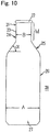
- the metal bottle can of Figure 10 is that in which the neck part and the mouth part are unified, and is that in which the taper portion 4a of Figure 1 is not equipped.
- the height M of the neck part is 20 mm to 50 mm, preferably 20 mm to 45 mm.
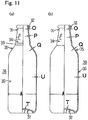
- the metal bottle can of Figure 11 comprises a cylindrical barrel part 36, a bottom part 37 closing the lower end thereof, a taper-shaped shoulder part 35 formed in the upper end of the barrel part, a cylindrical straight portion 39 formed in the upper end of the shoulder part, a taper-shaped neck part 34 formed in the upper end of the straight portion, and a mouth part 31 formed in the upper end of the neck part.
- a curl portion 32 is formed in the upper end of the mouth part.
- Figure 1 is a drawing showing the embodiment 1 of the present invention.
- a curl portion 2 is formed in the end of the mouth part, and a straight portion 3 in parallel to the can axis is formed down below the mouth part 1 in the neck part.
- the metal bottle can 8 has a long neck part 4.
- the straight portion 3 By the formation of the straight portion 3, the metal bottle 8 becomes easy to hold and easy to handle.
- the mouth part 1, neck part 4, shoulder part 5, barrel part 6, and bottom part 7 are integrally formed.
- the embodiment 1 is formed by drawing a primitive plate (wall thickness T) having thickness of 0.44mm.
- the embodiment 1 is formed to have the barrel part with diameter A of 60 mm, the neck part with diameter B of 27 mm and length S of 25 mm, and the shoulder part with the angle ⁇ of 54.5 degrees. Further, the embodiment is formed to have the mouth part with the wall thickness X of 0.43mm, and the straight portion of the neck part with the wall thickness Y of 0.40. The embodiment is formed to have the tapered-shaped shoulder part with a wall thickness Z of 0.29 mm, and the barrel part with the wall thickness W of 0.18 mm. The inventors etc. have found that even if the wall thickness of the barrel part 6 is thinner than that of the curl portion 2 and the neck part 4, the metal bottle can will have sufficient strength to withstand the load, and that the cost will be reduced by thinning.
- the primitive plate of the wall thickness of 0.40 mm, 0.38 mm, 0.36 mm etc. may be drawing processed. In this case, it goes without saying that the weight reduction and cost reduction are further attained by the using thinner primitive plate and maintains the strength.
- other than 3104-H19, 3004, 3204 etc. may be used as the plate material of aluminum alloy for the present invention.
- an easily openable cap 10 called maxi cap, rip cap etc. in popular name is wound and fastened to the curl portion 2. If the withstanding strength of the curl portion is insufficient, the curl portion 2 will deforms as shown by the dashed line, because of a pressing force applied to the curl portion 2 when the easily openable cap 10 is wounded and fastened. In such a case, there is a problem that the content leaks from the gap between the curl portion 2 and the easily openable cap 10.
- the curl portion 2 of the end of the mouth part 1 is formed to be thick with the wall thickness X' of 0.46 mm. The inventors etc.
- the inventors etc. have specified the range of the wall thickness where it is possible to attain the balance of thinning and weight reduction, while maintaining the strength of the curl portion 2.
- the specified range of the metal bottle can is that the size B of the neck part 4 is 20 mm to 35 mm, the outer diameter A of the barrel part 6 is 40 mm to 70 mm, the angle ⁇ of the shoulder part is 40 degrees to 70 degrees.
- the inventors etc. also have focused on the shape of the curl portion 2 itself as much as the wall thickness X' of the curl portion 2 having strength which withstand the loads.
- Figure 6 shows the other example of the curl portion 2 which does not deform.
- a pressure at which the content leaks from the easily openable cap 10 which is wound and fastened to the mouth part 1 of the metal bottle can of the embodiment 1 is 1.2 MPa or more.
- This configuration makes it possible to prevent a pull tab 10d of the easily openable cap 10 from protruding in a large way from the periphery of the size B of the neck part 4.
- the tongue piece connecting a skirt portion 10b extending downward from the top face wall 10a of the easily openable cap and a pull tab 10d is closely attached to the annular recessed portion 1a of the mouth part 2 of which the diameter is contracted.
- a plate material of aluminum alloy for example, the plate material of 3104-H19 is drawing processed first to form a bottomed cylindrical body having a barrel part. After that, necking processing is applied to the opening of the bottomed cylindrical body to form the planned forming portion of a mouth part and neck part having a straight portion. Then, a mouth part is formed by contracting the diameter of the upper portion of the planned forming portion. Next, a curl portion is formed in the end of the mouth part to complete. After a content is filled in the metal bottle can, an easily openable cap is wound and fastened to the curl portion.
- a metal bottle can having a screw formed in the lower portion of the mouth part of the embodiment 2.
- the planned forming portion having the mouth part and the neck part having a straight portion is formed.
- a male screw processing is applied to the planned forming portion beneath the mouth part
- a curl processing is applied to the end of the mouth part to complete.
- a cap cylinder body of cylindrical shape is covered on the mouth part, and a male screw is formed in the side face of the cap cylinder body by a screw forming machine.
- the top face of the planned cap cylinder body is pressed downward in the can axis direction using a pressure block, and a thread cutting roller is pressed around the can along the male screw of the mouth part of the metal bottle can to form a screw cap.
- Figure 7 is a drawing showing the embodiment 2 of the present invention.
- a curl portion 12 is formed in the end of a mouth part 11 and a male screw portion 11a is formed beneath the curl portion 12. Moreover, in the lower portion thereof, it has a straight portion 13 in parallel to the can axis. It is characterized in that a neck part 14 is formed long. Forming of the straight portion 13 allows easy holding and easy handling of the metal bottle can 18.
- a mouth part 11, neck part 14 having the straight portion 13, a taper-shaped shoulder part 15, a barrel part 16, and a bottom part 17 are formed by integral molding is same as the embodiment 1.
- the embodiment 2 is formed by drawing a primitive plate (wall thickness T) having thickness of 0.44mm similar to the embodiment 1.
- the embodiment 2 is formed to have the barrel part with diameter A of 60 mm, the neck part with diameter B of 27 mm and length L of 20 mm, and the shoulder part with the angle ⁇ of 54.5 degrees. Further, the embodiment 2 is formed to have the mouth part with the wall thickness E of 0.41mm, the screw portion with the wall thickness E' of 0.38 mm, and the straight portion 13 of the neck part 14 with the wall thickness F of 0.37.
- a semilunar curl portion 12a of which the cross section of the curl portion is not circular as shown in Figure 7 , may be formed.
- a planar portion 12b is formed in outside periphery thereof, and a semicircular portion 12c is formed from the top of the planar portion 12b to the top face including the inner perimeter of the top face.
- a protruded portion 12d is formed at the intersecting point of the planar portion 12b and the semicircular portion 12c.
- this semilunar curl portion 12a exists in the point that, when the mouth part 11 of the metal bottle can 18 is sealed by a screw cap, the protruded portion 12d bites into the packing of the cap, and the surface of the planar portion 12b strongly presses the packing making a firm sealing between the mouth part 11 and the cap. Accordingly, the quality of the content can be held even when a content having inner pressure is filled in.
- the depression of the screw portion 11a and the shoulder part 15, and the buckling etc. of the barrel part 16 can be prevented by forming the wall thickness G of the taper-shaped shoulder part 15 into 0.28 mm, and the wall thickness H of the barrel part into 0.18 mm, during the thread cutting process of the screw portion 11a of the capping processing where the metal bottle can receives the downward pressure in the can axis of the pressure block of about 1050 N.
- the balance of thinning and weight reduction can be attained, while maintaining the strength of the mouth part 11 and the screw portion 11a.
- the inventor has specified the wall thickness of the mouth part 11 and the screw portion 11a of the metal bottle can 18 of this embodiment 2.
- the metal bottle can 18 of the embodiment 2 is formed to have the tapered-shaped shoulder part with the wall thickness G of 0.33 mm-0.20 mm, and the barrel part with the wall thickness H of 0.22 mm-0.12 mm.
- the embodiment of Figure 9 is characterized in that the neck part 14 does not have a straight portion in parallel to the can axis. Even when the straight portion does not have the straight portion, each size of the mouth part 11, the male screw portion 11a, the neck part 14, and the shoulder part 15, the angle ⁇ , as well as the outer diameter of the mouth part 11 and the neck part 14 with regard to the barrel part 16 are specified so that the metal bottle can 18 is still easy to hold and easy to handle.
- the metal bottle can 18 of this embodiment having the mouth part 11, the neck part 14, the taper-shaped shoulder part 15, the barrel part 16, and the bottom part 17 is integrally formed by drawing processing the similar primitive plate (wall thickness T) of the thickness 0.44 mm.
- the diameter A of the barrel part is 60 mm
- the outer diameter of the mouth part is 28 mm ( Figure a) or 38 mm ( Figure b)
- the angle ⁇ of the shoulder part is 54.5 degrees.
- the wall thickness E of the mouth part is 0.41 mm
- the wall thickness E' of the screw portion is 0.38 mm.
- the semilunar curl portion 12a is formed similarly in the end of the mouth part 11 of the metal bottle can 18, and , the male screw portion 11a is formed beneath the curl potion 12a.
- a planar portion 12b is formed in outside periphery
- a semicircular portion 12c is formed from the top of the planar portion 12b to the top face including the inner perimeter of the top face.
- a protruded portion 12d is formed at the intersecting point of the planar portion 12b and the semicircular portion 12c.
- the wall thickness G of the shoulder part 15 and the wall thickness H of the barrel part are sufficient to withstand the pressure block pressure when in the processing and the buckling when in the thread cutting.
- Figure 10 is a drawing showing the embodiment 3 of the present invention.
- the metal bottle can 28 is characterized in that, a curl portion 22 is formed in the end of a mouth part 21, and a neck part 24 having a straight portion 23 in parallel to the can axis is formed to be long.
- the metal bottle can having the mouth part 21, the neck part 24, a shoulder part 25, a barrel part 26, and a bottom part 27 are integrally formed.
- the wall thickness of the primitive plate which will be drawing processed, the diameter A of the barrel part 26, the diameter B of the neck part 24, the angle ⁇ of the shoulder part 25, the wall thickness of the mouth part 21, the wall thickness of the neck part 24 are same as those of the embodiment 1.
- the wall thickness of the taper-shaped shoulder part 25 and the wall thickness of the barrel part 26 are also formed to be same as the embodiment 1.
- the point different from the embodiment 1 is that the length M of the straight portion of the neck part is 35 mm, and that the diameter of the upper portion of the neck part 24 is not contracted.
- Figure 11 is a drawing showing the embodiment 4 of the present invention.
- This metal bottle can 38 is characterized in that, while a curl portion 32 is formed in the end of the mouth part 31, the neck part 34 has a taper shape of angle ⁇ from beneath a mouth part 31 to a shoulder part 35a.
- the mouth part 31, the neck part 34, a shoulder part 35, a barrel part 36, and a bottom part 37 are integrally formed similarly by drawing processing the primitive plate (wall thickness T) of the thickness 0.44 mm.
- the diameter A of a barrel part 36 is 60 mm
- the angle ⁇ of the neck part 34 is 50 degrees to 89 degrees.
- the wall thickness O of the mouth part is 0.43 mm
- the wall thickness P of the taper-shaped neck part 34 is 0.40 mm
- the wall thickness Q of the shoulder part 35 is 0.29 mm
- the wall thickness U of the barrel part 36 is 0.18 mm.
- the easily openable cap is wound and fastened to the curl portion 32 to close the mouth part 31.
- the difference of the embodiment between the Figure (a) and Figure (b) of Figure 11 is that the embodiment of Figure (a) of Figure 11 somewhat has the straight portion 39 in parallel to the can axis between the neck part 34 and the shoulder part 35, but the embodiment of Figure (b) of Figure 11 do not have the straight portion in parallel to the can axis.
- the embodiment 2, the embodiment 3, and the embodiment 4 is a thinned metal bottle can 18, 28, 38, which has sufficient strength to withstand against a load applied when in forming the curl portion, a load applied when in capping the screw cap, or a load applied when in winding and fastening the easily openable cap.
- these are reasonable metal bottle cans 18, 28, 38 which have sufficient strength not to generate deformation, buckling of the mouth part, the neck part or the barrel part in the manufacturing, filling process, while the balance of thinning and weight reduction being attained.
- the metal bottle can of the present invention is a low cost metal bottle can in which the balance of thinning and weight reduction is attained while maintaining the strength. It can be widely used as a container for filling carbonated beverages such as beer, cola etc., refreshing liquids such as juice, tea etc., foods, health drinks, and medicals.
Landscapes
- Engineering & Computer Science (AREA)
- Ceramic Engineering (AREA)
- Mechanical Engineering (AREA)
- Containers Having Bodies Formed In One Piece (AREA)
- Closures For Containers (AREA)
Applications Claiming Priority (4)
| Application Number | Priority Date | Filing Date | Title |
|---|---|---|---|
| JP2009091910 | 2009-04-06 | ||
| JP2009167686 | 2009-07-16 | ||
| JP2009253801 | 2009-11-05 | ||
| EP10761708.6A EP2418155B1 (en) | 2009-04-06 | 2010-04-06 | Metal bottle can |
Related Parent Applications (2)
| Application Number | Title | Priority Date | Filing Date |
|---|---|---|---|
| EP10761708.6A Division EP2418155B1 (en) | 2009-04-06 | 2010-04-06 | Metal bottle can |
| EP10761708.6A Division-Into EP2418155B1 (en) | 2009-04-06 | 2010-04-06 | Metal bottle can |
Publications (1)
| Publication Number | Publication Date |
|---|---|
| EP3241773A1 true EP3241773A1 (en) | 2017-11-08 |
Family
ID=42936290
Family Applications (2)
| Application Number | Title | Priority Date | Filing Date |
|---|---|---|---|
| EP17175294.2A Withdrawn EP3241773A1 (en) | 2009-04-06 | 2010-04-06 | Metal bottle can |
| EP10761708.6A Not-in-force EP2418155B1 (en) | 2009-04-06 | 2010-04-06 | Metal bottle can |
Family Applications After (1)
| Application Number | Title | Priority Date | Filing Date |
|---|---|---|---|
| EP10761708.6A Not-in-force EP2418155B1 (en) | 2009-04-06 | 2010-04-06 | Metal bottle can |
Country Status (6)
| Country | Link |
|---|---|
| US (1) | US9227748B2 (enExample) |
| EP (2) | EP3241773A1 (enExample) |
| JP (3) | JP5323757B2 (enExample) |
| KR (1) | KR101746195B1 (enExample) |
| CN (2) | CN102378722B (enExample) |
| WO (1) | WO2010117009A1 (enExample) |
Families Citing this family (59)
| Publication number | Priority date | Publication date | Assignee | Title |
|---|---|---|---|---|
| US8668100B2 (en) * | 2010-06-30 | 2014-03-11 | S.C. Johnson & Son, Inc. | Bottles with top loading resistance |
| US8550272B2 (en) * | 2010-07-14 | 2013-10-08 | Graham Packaging Company, Lp | Extrusion blow molded pet container having superior column strength |
| WO2012133391A1 (ja) * | 2011-03-28 | 2012-10-04 | ユニバーサル製缶株式会社 | ねじ付きボトル缶の製造方法及びねじ付きボトル缶 |
| EP4484595A3 (en) | 2011-09-16 | 2025-07-23 | Ball Corporation | Method of manufacturing impact extruded containers from recycled aluminum scrap |
| USD1033215S1 (en) | 2012-08-10 | 2024-07-02 | Daniel A. Zabaleta | Container lid comprising frustum shaped sidewall and seaming chuck receiving radius |
| US12365511B1 (en) | 2012-08-10 | 2025-07-22 | Daniel A Zabaleta | Sealing cap having tamper evidence ring for sealing resealable container and method of use |
| US10968010B1 (en) | 2012-08-10 | 2021-04-06 | Daniel A Zabaleta | Resealable container lid and accessories including methods of manufacture and use |
| USD1033216S1 (en) | 2012-08-10 | 2024-07-02 | Daniel A. Zabaleta | Container cap having frustum shaped sidewall segment enabling nesting |
| US9139324B1 (en) | 2012-10-01 | 2015-09-22 | Aleco Container, LLC | Metal bottle type container with insert/outsert and related methodology |
| DE102012224253A1 (de) * | 2012-12-21 | 2014-06-26 | Hirschvogel Umformtechnik Gmbh | Einstückiges Werkstück mit einem Kanal sowie Herstellungsverfahren hierzu |
| PL2969784T3 (pl) | 2013-03-15 | 2024-11-04 | Ball Corporation | Sposób formowania gwintowanej szyjki na butelce metalowej i taka butelka |
| CN105324316B (zh) | 2013-04-09 | 2018-01-12 | 鲍尔公司 | 由再循环的铝和增强的合金制造的具有带螺纹的颈部的冲挤的铝瓶 |
| US10040593B2 (en) | 2014-02-07 | 2018-08-07 | Ball Corporation | Metallic container with a threaded closure |
| CN103786943A (zh) * | 2014-03-04 | 2014-05-14 | 广东欧亚包装有限公司 | 一种铝制包装瓶及其制造方法 |
| US20160122068A1 (en) | 2014-10-12 | 2016-05-05 | Michael Butter | Beverage container |
| CN104826958B (zh) * | 2015-03-13 | 2017-02-22 | 滁州嘉美印铁制罐有限公司 | 一种金属瓶制造工艺和金属瓶 |
| JP6182234B2 (ja) | 2015-04-06 | 2017-08-16 | 武内プレス工業株式会社 | ネジ付き金属容器 |
| KR101699708B1 (ko) | 2015-05-08 | 2017-01-25 | 대우조선해양 주식회사 | 응축수의 폐열을 이용한 선박 또는 해양 구조물용 온음용수 공급 장치 및 온음용수 공급 방법 |
| JP2018520008A (ja) * | 2015-07-06 | 2018-07-26 | ノベリス・インコーポレイテッドNovelis Inc. | 大型アルミニウムボトルを製造するプロセス及びそれよって製造されるアルミニウムボトル |
| MX2018012350A (es) * | 2016-04-08 | 2019-07-08 | Exal Corp | Metodo y aparato para producir un rebordeado enrollado en un extremo abierto de recipiente metalico. |
| JP6946620B2 (ja) * | 2016-04-27 | 2021-10-06 | 東洋製罐株式会社 | 缶体及び缶体口部のカール部形成方法 |
| US20180044155A1 (en) | 2016-08-12 | 2018-02-15 | Ball Corporation | Apparatus and Methods of Capping Metallic Bottles |
| JP2018039571A (ja) * | 2016-08-31 | 2018-03-15 | ユニバーサル製缶株式会社 | ボトル缶体、キャップ付きボトル缶体、ボトル缶体のキャッピング方法 |
| JP2019206343A (ja) * | 2016-10-03 | 2019-12-05 | Tmc Japan株式会社 | 金属容器および蓋体付金属容器 |
| JP2019206344A (ja) * | 2016-10-03 | 2019-12-05 | Tmc Japan株式会社 | 金属容器および蓋体付金属容器 |
| JP6877943B2 (ja) * | 2016-10-11 | 2021-05-26 | ユニバーサル製缶株式会社 | ボトル缶の製造方法 |
| JP6820728B2 (ja) * | 2016-11-29 | 2021-01-27 | ユニバーサル製缶株式会社 | ボトル缶およびその製造方法 |
| JP2018100121A (ja) * | 2016-12-21 | 2018-06-28 | ユニバーサル製缶株式会社 | キャップ本体、キャップ付きボトル缶体 |
| JP2018103254A (ja) * | 2016-12-28 | 2018-07-05 | ユニバーサル製缶株式会社 | ボトル缶、キャップ付きボトル缶およびその製造方法 |
| CA3177802A1 (en) | 2016-12-30 | 2018-07-05 | Ball Corporation | Aluminum alloy for impact extruded containers and method of making the same |
| JP6476219B2 (ja) * | 2017-02-10 | 2019-02-27 | ユニバーサル製缶株式会社 | ボトル缶の製造方法 |
| JP2018131261A (ja) * | 2017-02-16 | 2018-08-23 | ユニバーサル製缶株式会社 | ボトル缶の製造方法 |
| US10875684B2 (en) | 2017-02-16 | 2020-12-29 | Ball Corporation | Apparatus and methods of forming and applying roll-on pilfer proof closures on the threaded neck of metal containers |
| WO2018170249A1 (en) * | 2017-03-15 | 2018-09-20 | Berry Global, Inc. | Container having varying wall thickness |
| EP3604157A4 (en) * | 2017-03-22 | 2020-07-15 | Toyo Seikan Co., Ltd. | METAL CAN AND MANUFACTURING METHOD THEREOF |
| JP6515952B2 (ja) * | 2017-05-19 | 2019-05-22 | 東洋製罐株式会社 | ボトル缶、キャップ付きボトル缶、及びボトル缶の製造方法 |
| JP6754340B2 (ja) * | 2017-08-25 | 2020-09-09 | 東洋製罐株式会社 | ボトル缶及びキャップ付きボトル缶 |
| AU2018334223B2 (en) | 2017-09-15 | 2021-11-11 | Ball Corporation | System and method of forming a metallic closure for a threaded container |
| JP6965076B2 (ja) * | 2017-09-25 | 2021-11-10 | ユニバーサル製缶株式会社 | ボトル缶の製造方法 |
| JP7060349B2 (ja) * | 2017-09-25 | 2022-04-26 | ユニバーサル製缶株式会社 | ボトル缶の製造方法 |
| JP7206046B2 (ja) * | 2018-02-14 | 2023-01-17 | アルテミラ製缶株式会社 | ボトル缶およびボトル缶の製造方法 |
| JP7112697B2 (ja) * | 2018-03-27 | 2022-08-04 | アルテミラ製缶株式会社 | 缶体及びカール部構造 |
| JP7207873B2 (ja) * | 2018-06-25 | 2023-01-18 | アルテミラ製缶株式会社 | ボトル缶の製造方法 |
| JP7419746B2 (ja) * | 2018-10-22 | 2024-01-23 | アルテミラ製缶株式会社 | ボトル缶 |
| MX2021005230A (es) | 2018-11-05 | 2021-06-18 | Ball Corp | Recipiente metalico con una tapa roscada. |
| JP7447443B2 (ja) * | 2018-12-04 | 2024-03-12 | アルテミラ製缶株式会社 | 缶体 |
| EP3919202A4 (en) * | 2019-01-28 | 2022-10-26 | Universal Can Corporation | CAN BODY AND PROCESS FOR MANUFACTURE THEREOF |
| BR112021026071A2 (pt) | 2019-06-26 | 2022-02-08 | Ball Corp | Método e aparelho para selar um recipiente metálico com um fechamento de extremidade metálica |
| JP7133586B2 (ja) * | 2020-05-25 | 2022-09-08 | キリンホールディングス株式会社 | 缶体 |
| CN116648412A (zh) * | 2020-09-16 | 2023-08-25 | 东洋制罐株式会社 | 杯子及其制造方法 |
| FR3116811B1 (fr) * | 2020-11-30 | 2025-10-10 | Trivium Packaging Group Netherlands B V | Procédé pour la fabrication d’un emballage métallique en forme de bouteille |
| WO2022212206A1 (en) * | 2021-03-29 | 2022-10-06 | Belvac Production Machinery, Inc. | Method for forming a metal container with a carrier ring and resulting container |
| US12384594B2 (en) | 2021-04-05 | 2025-08-12 | Daniel A. Zabaleta | Threaded container components having frustum shaped surfaces enabling nesting |
| US20230038281A1 (en) * | 2021-08-06 | 2023-02-09 | Vita-Mix Management Corporation | Container for immersion blender |
| JP2023060971A (ja) * | 2021-10-19 | 2023-05-01 | 東洋製罐株式会社 | 缶体 |
| JP2023102644A (ja) * | 2022-01-12 | 2023-07-25 | 大和製罐株式会社 | ボトル型缶およびボトル型缶用粗形材 |
| JP2023102643A (ja) * | 2022-01-12 | 2023-07-25 | 大和製罐株式会社 | 広口ボトル型缶 |
| WO2023150699A1 (en) | 2022-02-04 | 2023-08-10 | Ball Corporation | Method for forming a curl and a threaded metallic container including the same |
| WO2024196895A1 (en) | 2023-03-17 | 2024-09-26 | Belvac Production Machinery, Inc. | Metal container with a carrier ring and methods of making the same |
Citations (1)
| Publication number | Priority date | Publication date | Assignee | Title |
|---|---|---|---|---|
| US6959830B1 (en) * | 1999-11-26 | 2005-11-01 | Takeuchi Press Industries Co., Ltd. | Metal container with thread |
Family Cites Families (26)
| Publication number | Priority date | Publication date | Assignee | Title |
|---|---|---|---|---|
| JPS4818547U (enExample) * | 1972-04-05 | 1973-03-02 | ||
| IT1193561B (it) * | 1980-11-28 | 1988-07-08 | Ligure Tubettificio | Processo per la fabbricazione di corpi metallici cavi monoblocco a pareti sottili,per contenitori a pressione |
| JPS59181041U (ja) * | 1983-05-18 | 1984-12-03 | 株式会社日本アルミ | 薄板金属製容器の口金 |
| DE9200027U1 (de) * | 1992-01-03 | 1993-06-17 | Bürkle, Felix, 72414 Rangendingen | Aluminiumflasche |
| US5718352A (en) * | 1994-11-22 | 1998-02-17 | Aluminum Company Of America | Threaded aluminum cans and methods of manufacture |
| US5755354A (en) * | 1994-10-07 | 1998-05-26 | Engelbrauerei Schwaebisch Gmuend, Luise Lang Gmbh & Co. Kg | Beverage can |
| US6010028A (en) * | 1994-11-22 | 2000-01-04 | Aluminum Company Of America | Lightweight reclosable can with attached threaded pour spout and methods of manufacture |
| FR2775206B1 (fr) * | 1998-02-26 | 2000-04-21 | Cebal | Procede pour realiser un boitier aerosol a col filete |
| US6264050B1 (en) * | 1998-10-06 | 2001-07-24 | Plastipak Packaging, Inc. | Container with improved neck portion and method for making the same |
| JP4284786B2 (ja) * | 1999-10-22 | 2009-06-24 | 東洋製罐株式会社 | 薄肉ボトルの製造方法 |
| JP4301534B2 (ja) * | 1999-11-11 | 2009-07-22 | 大和製罐株式会社 | ネジ付き缶用キャップの密封ライナー構造 |
| US20030102278A1 (en) * | 2001-12-04 | 2003-06-05 | Thomas Chupak | Aluminum receptacle with threaded outsert |
| JP2004083128A (ja) * | 2001-12-28 | 2004-03-18 | Mitsubishi Materials Corp | ボトル缶体およびボトル |
| JP4115133B2 (ja) * | 2002-01-17 | 2008-07-09 | 大和製罐株式会社 | ボトル型缶およびその製造方法 |
| US20040035871A1 (en) * | 2002-08-20 | 2004-02-26 | Thomas Chupak | Aluminum aerosol can and aluminum bottle and method of manufacture |
| JP4159956B2 (ja) * | 2003-09-26 | 2008-10-01 | ユニバーサル製缶株式会社 | ボトル缶およびキャップ付ボトル缶 |
| JP2005271973A (ja) * | 2004-03-25 | 2005-10-06 | Mitsubishi Materials Corp | ボトル缶およびキャップ付ボトル缶 |
| JP4788234B2 (ja) * | 2005-08-12 | 2011-10-05 | Jfeスチール株式会社 | 2ピース缶用ラミネート鋼板及び2ピースラミネート缶 |
| US20070051687A1 (en) * | 2005-09-07 | 2007-03-08 | Omnitech International, Inc | Reclosable metal bottle |
| JP4762674B2 (ja) * | 2005-10-28 | 2011-08-31 | 株式会社吉野工業所 | 合成樹脂製ボトル型容器 |
| JP4800023B2 (ja) * | 2005-12-02 | 2011-10-26 | 大和製罐株式会社 | アルミニウム合金製小容量ネジ付き缶 |
| US8016148B2 (en) * | 2006-07-12 | 2011-09-13 | Rexam Beverage Can Company | Necked-in can body and method for making same |
| US20080047922A1 (en) * | 2006-08-22 | 2008-02-28 | Olson Christopher J | Metal bottle seal |
| JP2008057019A (ja) * | 2006-09-01 | 2008-03-13 | Universal Seikan Kk | 飲料缶用アルミニウム合金板およびそれを用いた容器 |
| JP4880518B2 (ja) * | 2007-05-10 | 2012-02-22 | 日本クラウンコルク株式会社 | 簡易開栓キャップ |
| US8024788B2 (en) * | 2007-05-31 | 2011-09-20 | The Boeing Company | Method and apparatus for reliable, high speed data transfers in a high assurance multiple level secure environment |
-
2010
- 2010-04-06 JP JP2010088194A patent/JP5323757B2/ja active Active
- 2010-04-06 EP EP17175294.2A patent/EP3241773A1/en not_active Withdrawn
- 2010-04-06 EP EP10761708.6A patent/EP2418155B1/en not_active Not-in-force
- 2010-04-06 CN CN201080015158.6A patent/CN102378722B/zh not_active Expired - Fee Related
- 2010-04-06 WO PCT/JP2010/056267 patent/WO2010117009A1/ja not_active Ceased
- 2010-04-06 CN CN201410265547.4A patent/CN104029881B/zh not_active Expired - Fee Related
- 2010-04-06 KR KR1020117026240A patent/KR101746195B1/ko not_active Expired - Fee Related
- 2010-04-06 US US13/259,247 patent/US9227748B2/en not_active Expired - Fee Related
-
2012
- 2012-07-17 JP JP2012159102A patent/JP5597333B2/ja active Active
-
2013
- 2013-06-24 JP JP2013131623A patent/JP5631449B2/ja active Active
Patent Citations (1)
| Publication number | Priority date | Publication date | Assignee | Title |
|---|---|---|---|---|
| US6959830B1 (en) * | 1999-11-26 | 2005-11-01 | Takeuchi Press Industries Co., Ltd. | Metal container with thread |
Also Published As
| Publication number | Publication date |
|---|---|
| JP2011116456A (ja) | 2011-06-16 |
| JP2013227083A (ja) | 2013-11-07 |
| EP2418155B1 (en) | 2017-07-26 |
| CN104029881B (zh) | 2017-05-03 |
| CN102378722B (zh) | 2014-07-16 |
| US20120024813A1 (en) | 2012-02-02 |
| WO2010117009A1 (ja) | 2010-10-14 |
| JP5323757B2 (ja) | 2013-10-23 |
| CN104029881A (zh) | 2014-09-10 |
| JP2012192984A (ja) | 2012-10-11 |
| KR101746195B1 (ko) | 2017-06-12 |
| EP2418155A4 (en) | 2012-08-22 |
| KR20120006037A (ko) | 2012-01-17 |
| JP5631449B2 (ja) | 2014-11-26 |
| CN102378722A (zh) | 2012-03-14 |
| US9227748B2 (en) | 2016-01-05 |
| EP2418155A1 (en) | 2012-02-15 |
| JP5597333B2 (ja) | 2014-10-01 |
Similar Documents
| Publication | Publication Date | Title |
|---|---|---|
| EP2418155B1 (en) | Metal bottle can | |
| JP2012192984A5 (enExample) | ||
| US11130607B2 (en) | Bottle can, bottle can with cap, and method for manufacturing bottle can | |
| US20040045967A1 (en) | Reclosable metal beverage can | |
| CA2735911C (en) | Can end | |
| JPH11139438A (ja) | 開封後の再閉鎖が可能で飲み易い飲料用金属容器およびその製造方法 | |
| US20070102434A1 (en) | Reclosable metal container | |
| CN2913201Y (zh) | 可重新封闭的容器 | |
| JP2007509006A (ja) | 再閉塞可能な飲料用缶(缶、缶及びカップ) | |
| JP2011051595A (ja) | 容器のキャッピング方法および容器詰め飲料 | |
| EP3674225A1 (en) | Bottle-shaped can and capped bottle-shaped can | |
| JP2022177092A (ja) | ボトル缶体、キャップ付きボトル缶体、ボトル缶体のキャッピング方法 | |
| JP2013091076A (ja) | リシール缶、リシール缶の缶本体及びリシール缶への内容物の充填方法 | |
| US20250229962A1 (en) | Container and metallic closure with a floating liner | |
| NL2000169C2 (nl) | Levensmiddelenhouder, in het bijzonder een drankblikje, en werkwijze voor het vervaardigen van een dergelijke levensmiddelenhouder. | |
| JP2019156428A (ja) | 缶体 | |
| JP2003011968A (ja) | ボトル型缶 |
Legal Events
| Date | Code | Title | Description |
|---|---|---|---|
| PUAI | Public reference made under article 153(3) epc to a published international application that has entered the european phase |
Free format text: ORIGINAL CODE: 0009012 |
|
| STAA | Information on the status of an ep patent application or granted ep patent |
Free format text: STATUS: REQUEST FOR EXAMINATION WAS MADE |
|
| 17P | Request for examination filed |
Effective date: 20170609 |
|
| AC | Divisional application: reference to earlier application |
Ref document number: 2418155 Country of ref document: EP Kind code of ref document: P |
|
| AK | Designated contracting states |
Kind code of ref document: A1 Designated state(s): AT BE BG CH CY CZ DE DK EE ES FI FR GB GR HR HU IE IS IT LI LT LU LV MC MK MT NL NO PL PT RO SE SI SK SM TR |
|
| R17P | Request for examination filed (corrected) |
Effective date: 20170609 |
|
| STAA | Information on the status of an ep patent application or granted ep patent |
Free format text: STATUS: EXAMINATION IS IN PROGRESS |
|
| 17Q | First examination report despatched |
Effective date: 20201021 |
|
| STAA | Information on the status of an ep patent application or granted ep patent |
Free format text: STATUS: THE APPLICATION IS DEEMED TO BE WITHDRAWN |
|
| 18D | Application deemed to be withdrawn |
Effective date: 20210302 |