EP3229870B1 - Vielseitige spritzenplattform - Google Patents
Vielseitige spritzenplattform Download PDFInfo
- Publication number
- EP3229870B1 EP3229870B1 EP15841009.2A EP15841009A EP3229870B1 EP 3229870 B1 EP3229870 B1 EP 3229870B1 EP 15841009 A EP15841009 A EP 15841009A EP 3229870 B1 EP3229870 B1 EP 3229870B1
- Authority
- EP
- European Patent Office
- Prior art keywords
- knob
- plunger
- medicament
- rod
- rotation
- Prior art date
- Legal status (The legal status is an assumption and is not a legal conclusion. Google has not performed a legal analysis and makes no representation as to the accuracy of the status listed.)
- Active
Links
Images


Classifications
-
- A—HUMAN NECESSITIES
- A61—MEDICAL OR VETERINARY SCIENCE; HYGIENE
- A61F—FILTERS IMPLANTABLE INTO BLOOD VESSELS; PROSTHESES; DEVICES PROVIDING PATENCY TO, OR PREVENTING COLLAPSING OF, TUBULAR STRUCTURES OF THE BODY, e.g. STENTS; ORTHOPAEDIC, NURSING OR CONTRACEPTIVE DEVICES; FOMENTATION; TREATMENT OR PROTECTION OF EYES OR EARS; BANDAGES, DRESSINGS OR ABSORBENT PADS; FIRST-AID KITS
- A61F9/00—Methods or devices for treatment of the eyes; Devices for putting in contact-lenses; Devices to correct squinting; Apparatus to guide the blind; Protective devices for the eyes, carried on the body or in the hand
- A61F9/0008—Introducing ophthalmic products into the ocular cavity or retaining products therein
- A61F9/0017—Introducing ophthalmic products into the ocular cavity or retaining products therein implantable in, or in contact with, the eye, e.g. ocular inserts
-
- A—HUMAN NECESSITIES
- A61—MEDICAL OR VETERINARY SCIENCE; HYGIENE
- A61M—DEVICES FOR INTRODUCING MEDIA INTO, OR ONTO, THE BODY; DEVICES FOR TRANSDUCING BODY MEDIA OR FOR TAKING MEDIA FROM THE BODY; DEVICES FOR PRODUCING OR ENDING SLEEP OR STUPOR
- A61M5/00—Devices for bringing media into the body in a subcutaneous, intra-vascular or intramuscular way; Accessories therefor, e.g. filling or cleaning devices, arm-rests
- A61M5/178—Syringes
- A61M5/24—Ampoule syringes, i.e. syringes with needle for use in combination with replaceable ampoules or carpules, e.g. automatic
- A61M5/2448—Ampoule syringes, i.e. syringes with needle for use in combination with replaceable ampoules or carpules, e.g. automatic comprising means for injection of two or more media, e.g. by mixing
-
- A—HUMAN NECESSITIES
- A61—MEDICAL OR VETERINARY SCIENCE; HYGIENE
- A61M—DEVICES FOR INTRODUCING MEDIA INTO, OR ONTO, THE BODY; DEVICES FOR TRANSDUCING BODY MEDIA OR FOR TAKING MEDIA FROM THE BODY; DEVICES FOR PRODUCING OR ENDING SLEEP OR STUPOR
- A61M5/00—Devices for bringing media into the body in a subcutaneous, intra-vascular or intramuscular way; Accessories therefor, e.g. filling or cleaning devices, arm-rests
- A61M5/178—Syringes
- A61M5/24—Ampoule syringes, i.e. syringes with needle for use in combination with replaceable ampoules or carpules, e.g. automatic
- A61M5/2455—Ampoule syringes, i.e. syringes with needle for use in combination with replaceable ampoules or carpules, e.g. automatic with sealing means to be broken or opened
- A61M5/2459—Ampoule syringes, i.e. syringes with needle for use in combination with replaceable ampoules or carpules, e.g. automatic with sealing means to be broken or opened upon internal pressure increase, e.g. pierced or burst
-
- A—HUMAN NECESSITIES
- A61—MEDICAL OR VETERINARY SCIENCE; HYGIENE
- A61M—DEVICES FOR INTRODUCING MEDIA INTO, OR ONTO, THE BODY; DEVICES FOR TRANSDUCING BODY MEDIA OR FOR TAKING MEDIA FROM THE BODY; DEVICES FOR PRODUCING OR ENDING SLEEP OR STUPOR
- A61M5/00—Devices for bringing media into the body in a subcutaneous, intra-vascular or intramuscular way; Accessories therefor, e.g. filling or cleaning devices, arm-rests
- A61M5/178—Syringes
- A61M5/31—Details
- A61M5/3129—Syringe barrels
- A61M5/3137—Specially designed finger grip means, e.g. for easy manipulation of the syringe rod
-
- A—HUMAN NECESSITIES
- A61—MEDICAL OR VETERINARY SCIENCE; HYGIENE
- A61M—DEVICES FOR INTRODUCING MEDIA INTO, OR ONTO, THE BODY; DEVICES FOR TRANSDUCING BODY MEDIA OR FOR TAKING MEDIA FROM THE BODY; DEVICES FOR PRODUCING OR ENDING SLEEP OR STUPOR
- A61M5/00—Devices for bringing media into the body in a subcutaneous, intra-vascular or intramuscular way; Accessories therefor, e.g. filling or cleaning devices, arm-rests
- A61M5/178—Syringes
- A61M5/31—Details
- A61M5/3145—Filters incorporated in syringes
-
- A—HUMAN NECESSITIES
- A61—MEDICAL OR VETERINARY SCIENCE; HYGIENE
- A61M—DEVICES FOR INTRODUCING MEDIA INTO, OR ONTO, THE BODY; DEVICES FOR TRANSDUCING BODY MEDIA OR FOR TAKING MEDIA FROM THE BODY; DEVICES FOR PRODUCING OR ENDING SLEEP OR STUPOR
- A61M5/00—Devices for bringing media into the body in a subcutaneous, intra-vascular or intramuscular way; Accessories therefor, e.g. filling or cleaning devices, arm-rests
- A61M5/178—Syringes
- A61M5/31—Details
- A61M5/3146—Priming, e.g. purging, reducing backlash or clearance
-
- A—HUMAN NECESSITIES
- A61—MEDICAL OR VETERINARY SCIENCE; HYGIENE
- A61M—DEVICES FOR INTRODUCING MEDIA INTO, OR ONTO, THE BODY; DEVICES FOR TRANSDUCING BODY MEDIA OR FOR TAKING MEDIA FROM THE BODY; DEVICES FOR PRODUCING OR ENDING SLEEP OR STUPOR
- A61M5/00—Devices for bringing media into the body in a subcutaneous, intra-vascular or intramuscular way; Accessories therefor, e.g. filling or cleaning devices, arm-rests
- A61M5/178—Syringes
- A61M5/31—Details
- A61M5/315—Pistons; Piston-rods; Guiding, blocking or restricting the movement of the rod or piston; Appliances on the rod for facilitating dosing ; Dosing mechanisms
- A61M5/31501—Means for blocking or restricting the movement of the rod or piston
- A61M5/31505—Integral with the syringe barrel, i.e. connected to the barrel so as to make up a single complete piece or unit
-
- A—HUMAN NECESSITIES
- A61—MEDICAL OR VETERINARY SCIENCE; HYGIENE
- A61M—DEVICES FOR INTRODUCING MEDIA INTO, OR ONTO, THE BODY; DEVICES FOR TRANSDUCING BODY MEDIA OR FOR TAKING MEDIA FROM THE BODY; DEVICES FOR PRODUCING OR ENDING SLEEP OR STUPOR
- A61M5/00—Devices for bringing media into the body in a subcutaneous, intra-vascular or intramuscular way; Accessories therefor, e.g. filling or cleaning devices, arm-rests
- A61M5/178—Syringes
- A61M5/31—Details
- A61M5/315—Pistons; Piston-rods; Guiding, blocking or restricting the movement of the rod or piston; Appliances on the rod for facilitating dosing ; Dosing mechanisms
- A61M5/31511—Piston or piston-rod constructions, e.g. connection of piston with piston-rod
- A61M5/31513—Piston constructions to improve sealing or sliding
-
- A—HUMAN NECESSITIES
- A61—MEDICAL OR VETERINARY SCIENCE; HYGIENE
- A61M—DEVICES FOR INTRODUCING MEDIA INTO, OR ONTO, THE BODY; DEVICES FOR TRANSDUCING BODY MEDIA OR FOR TAKING MEDIA FROM THE BODY; DEVICES FOR PRODUCING OR ENDING SLEEP OR STUPOR
- A61M5/00—Devices for bringing media into the body in a subcutaneous, intra-vascular or intramuscular way; Accessories therefor, e.g. filling or cleaning devices, arm-rests
- A61M5/178—Syringes
- A61M5/31—Details
- A61M5/315—Pistons; Piston-rods; Guiding, blocking or restricting the movement of the rod or piston; Appliances on the rod for facilitating dosing ; Dosing mechanisms
- A61M5/31525—Dosing
- A61M5/31528—Dosing by means of rotational movements, e.g. screw-thread mechanisms
-
- A—HUMAN NECESSITIES
- A61—MEDICAL OR VETERINARY SCIENCE; HYGIENE
- A61M—DEVICES FOR INTRODUCING MEDIA INTO, OR ONTO, THE BODY; DEVICES FOR TRANSDUCING BODY MEDIA OR FOR TAKING MEDIA FROM THE BODY; DEVICES FOR PRODUCING OR ENDING SLEEP OR STUPOR
- A61M5/00—Devices for bringing media into the body in a subcutaneous, intra-vascular or intramuscular way; Accessories therefor, e.g. filling or cleaning devices, arm-rests
- A61M5/178—Syringes
- A61M5/31—Details
- A61M5/315—Pistons; Piston-rods; Guiding, blocking or restricting the movement of the rod or piston; Appliances on the rod for facilitating dosing ; Dosing mechanisms
- A61M5/31565—Administration mechanisms, i.e. constructional features, modes of administering a dose
- A61M5/31566—Means improving security or handling thereof
- A61M5/3157—Means providing feedback signals when administration is completed
-
- A—HUMAN NECESSITIES
- A61—MEDICAL OR VETERINARY SCIENCE; HYGIENE
- A61M—DEVICES FOR INTRODUCING MEDIA INTO, OR ONTO, THE BODY; DEVICES FOR TRANSDUCING BODY MEDIA OR FOR TAKING MEDIA FROM THE BODY; DEVICES FOR PRODUCING OR ENDING SLEEP OR STUPOR
- A61M5/00—Devices for bringing media into the body in a subcutaneous, intra-vascular or intramuscular way; Accessories therefor, e.g. filling or cleaning devices, arm-rests
- A61M5/178—Syringes
- A61M5/31—Details
- A61M5/315—Pistons; Piston-rods; Guiding, blocking or restricting the movement of the rod or piston; Appliances on the rod for facilitating dosing ; Dosing mechanisms
- A61M5/31565—Administration mechanisms, i.e. constructional features, modes of administering a dose
- A61M5/31566—Means improving security or handling thereof
- A61M5/31573—Accuracy improving means
-
- A—HUMAN NECESSITIES
- A61—MEDICAL OR VETERINARY SCIENCE; HYGIENE
- A61M—DEVICES FOR INTRODUCING MEDIA INTO, OR ONTO, THE BODY; DEVICES FOR TRANSDUCING BODY MEDIA OR FOR TAKING MEDIA FROM THE BODY; DEVICES FOR PRODUCING OR ENDING SLEEP OR STUPOR
- A61M5/00—Devices for bringing media into the body in a subcutaneous, intra-vascular or intramuscular way; Accessories therefor, e.g. filling or cleaning devices, arm-rests
- A61M5/178—Syringes
- A61M5/31—Details
- A61M5/315—Pistons; Piston-rods; Guiding, blocking or restricting the movement of the rod or piston; Appliances on the rod for facilitating dosing ; Dosing mechanisms
- A61M5/31565—Administration mechanisms, i.e. constructional features, modes of administering a dose
- A61M5/31576—Constructional features or modes of drive mechanisms for piston rods
- A61M5/31578—Constructional features or modes of drive mechanisms for piston rods based on axial translation, i.e. components directly operatively associated and axially moved with plunger rod
- A61M5/31581—Constructional features or modes of drive mechanisms for piston rods based on axial translation, i.e. components directly operatively associated and axially moved with plunger rod performed by rotationally moving or pivoting actuator operated by user, e.g. an injection lever or handle
-
- A—HUMAN NECESSITIES
- A61—MEDICAL OR VETERINARY SCIENCE; HYGIENE
- A61M—DEVICES FOR INTRODUCING MEDIA INTO, OR ONTO, THE BODY; DEVICES FOR TRANSDUCING BODY MEDIA OR FOR TAKING MEDIA FROM THE BODY; DEVICES FOR PRODUCING OR ENDING SLEEP OR STUPOR
- A61M5/00—Devices for bringing media into the body in a subcutaneous, intra-vascular or intramuscular way; Accessories therefor, e.g. filling or cleaning devices, arm-rests
- A61M5/178—Syringes
- A61M5/31—Details
- A61M5/315—Pistons; Piston-rods; Guiding, blocking or restricting the movement of the rod or piston; Appliances on the rod for facilitating dosing ; Dosing mechanisms
- A61M5/31565—Administration mechanisms, i.e. constructional features, modes of administering a dose
- A61M5/31576—Constructional features or modes of drive mechanisms for piston rods
- A61M5/31583—Constructional features or modes of drive mechanisms for piston rods based on rotational translation, i.e. movement of piston rod is caused by relative rotation between the user activated actuator and the piston rod
- A61M5/31586—Constructional features or modes of drive mechanisms for piston rods based on rotational translation, i.e. movement of piston rod is caused by relative rotation between the user activated actuator and the piston rod performed by rotationally moving or pivoted actuator, e.g. an injection lever or handle
-
- A—HUMAN NECESSITIES
- A61—MEDICAL OR VETERINARY SCIENCE; HYGIENE
- A61M—DEVICES FOR INTRODUCING MEDIA INTO, OR ONTO, THE BODY; DEVICES FOR TRANSDUCING BODY MEDIA OR FOR TAKING MEDIA FROM THE BODY; DEVICES FOR PRODUCING OR ENDING SLEEP OR STUPOR
- A61M5/00—Devices for bringing media into the body in a subcutaneous, intra-vascular or intramuscular way; Accessories therefor, e.g. filling or cleaning devices, arm-rests
- A61M5/178—Syringes
- A61M5/31—Details
- A61M5/315—Pistons; Piston-rods; Guiding, blocking or restricting the movement of the rod or piston; Appliances on the rod for facilitating dosing ; Dosing mechanisms
- A61M5/31596—Pistons; Piston-rods; Guiding, blocking or restricting the movement of the rod or piston; Appliances on the rod for facilitating dosing ; Dosing mechanisms comprising means for injection of two or more media, e.g. by mixing
-
- A—HUMAN NECESSITIES
- A61—MEDICAL OR VETERINARY SCIENCE; HYGIENE
- A61M—DEVICES FOR INTRODUCING MEDIA INTO, OR ONTO, THE BODY; DEVICES FOR TRANSDUCING BODY MEDIA OR FOR TAKING MEDIA FROM THE BODY; DEVICES FOR PRODUCING OR ENDING SLEEP OR STUPOR
- A61M5/00—Devices for bringing media into the body in a subcutaneous, intra-vascular or intramuscular way; Accessories therefor, e.g. filling or cleaning devices, arm-rests
- A61M5/178—Syringes
- A61M5/31—Details
- A61M5/32—Needles; Details of needles pertaining to their connection with syringe or hub; Accessories for bringing the needle into, or holding the needle on, the body; Devices for protection of needles
- A61M5/3202—Devices for protection of the needle before use, e.g. caps
-
- A—HUMAN NECESSITIES
- A61—MEDICAL OR VETERINARY SCIENCE; HYGIENE
- A61M—DEVICES FOR INTRODUCING MEDIA INTO, OR ONTO, THE BODY; DEVICES FOR TRANSDUCING BODY MEDIA OR FOR TAKING MEDIA FROM THE BODY; DEVICES FOR PRODUCING OR ENDING SLEEP OR STUPOR
- A61M5/00—Devices for bringing media into the body in a subcutaneous, intra-vascular or intramuscular way; Accessories therefor, e.g. filling or cleaning devices, arm-rests
- A61M5/178—Syringes
- A61M5/31—Details
- A61M5/32—Needles; Details of needles pertaining to their connection with syringe or hub; Accessories for bringing the needle into, or holding the needle on, the body; Devices for protection of needles
- A61M5/3295—Multiple needle devices, e.g. a plurality of needles arranged coaxially or in parallel
- A61M5/3298—Needles arranged in parallel
-
- A—HUMAN NECESSITIES
- A61—MEDICAL OR VETERINARY SCIENCE; HYGIENE
- A61M—DEVICES FOR INTRODUCING MEDIA INTO, OR ONTO, THE BODY; DEVICES FOR TRANSDUCING BODY MEDIA OR FOR TAKING MEDIA FROM THE BODY; DEVICES FOR PRODUCING OR ENDING SLEEP OR STUPOR
- A61M5/00—Devices for bringing media into the body in a subcutaneous, intra-vascular or intramuscular way; Accessories therefor, e.g. filling or cleaning devices, arm-rests
- A61M5/36—Devices for bringing media into the body in a subcutaneous, intra-vascular or intramuscular way; Accessories therefor, e.g. filling or cleaning devices, arm-rests with means for eliminating or preventing injection or infusion of air into body
-
- A—HUMAN NECESSITIES
- A61—MEDICAL OR VETERINARY SCIENCE; HYGIENE
- A61M—DEVICES FOR INTRODUCING MEDIA INTO, OR ONTO, THE BODY; DEVICES FOR TRANSDUCING BODY MEDIA OR FOR TAKING MEDIA FROM THE BODY; DEVICES FOR PRODUCING OR ENDING SLEEP OR STUPOR
- A61M5/00—Devices for bringing media into the body in a subcutaneous, intra-vascular or intramuscular way; Accessories therefor, e.g. filling or cleaning devices, arm-rests
- A61M5/178—Syringes
- A61M5/24—Ampoule syringes, i.e. syringes with needle for use in combination with replaceable ampoules or carpules, e.g. automatic
- A61M5/2448—Ampoule syringes, i.e. syringes with needle for use in combination with replaceable ampoules or carpules, e.g. automatic comprising means for injection of two or more media, e.g. by mixing
- A61M2005/2451—Ampoule syringes, i.e. syringes with needle for use in combination with replaceable ampoules or carpules, e.g. automatic comprising means for injection of two or more media, e.g. by mixing preventing delivery before mixing is completed, e.g. by locking mechanisms
-
- A—HUMAN NECESSITIES
- A61—MEDICAL OR VETERINARY SCIENCE; HYGIENE
- A61M—DEVICES FOR INTRODUCING MEDIA INTO, OR ONTO, THE BODY; DEVICES FOR TRANSDUCING BODY MEDIA OR FOR TAKING MEDIA FROM THE BODY; DEVICES FOR PRODUCING OR ENDING SLEEP OR STUPOR
- A61M5/00—Devices for bringing media into the body in a subcutaneous, intra-vascular or intramuscular way; Accessories therefor, e.g. filling or cleaning devices, arm-rests
- A61M5/178—Syringes
- A61M5/31—Details
- A61M5/315—Pistons; Piston-rods; Guiding, blocking or restricting the movement of the rod or piston; Appliances on the rod for facilitating dosing ; Dosing mechanisms
- A61M5/31501—Means for blocking or restricting the movement of the rod or piston
- A61M2005/31508—Means for blocking or restricting the movement of the rod or piston provided on the piston-rod
-
- A—HUMAN NECESSITIES
- A61—MEDICAL OR VETERINARY SCIENCE; HYGIENE
- A61M—DEVICES FOR INTRODUCING MEDIA INTO, OR ONTO, THE BODY; DEVICES FOR TRANSDUCING BODY MEDIA OR FOR TAKING MEDIA FROM THE BODY; DEVICES FOR PRODUCING OR ENDING SLEEP OR STUPOR
- A61M2205/00—General characteristics of the apparatus
- A61M2205/58—Means for facilitating use, e.g. by people with impaired vision
- A61M2205/581—Means for facilitating use, e.g. by people with impaired vision by audible feedback
-
- A—HUMAN NECESSITIES
- A61—MEDICAL OR VETERINARY SCIENCE; HYGIENE
- A61M—DEVICES FOR INTRODUCING MEDIA INTO, OR ONTO, THE BODY; DEVICES FOR TRANSDUCING BODY MEDIA OR FOR TAKING MEDIA FROM THE BODY; DEVICES FOR PRODUCING OR ENDING SLEEP OR STUPOR
- A61M2205/00—General characteristics of the apparatus
- A61M2205/58—Means for facilitating use, e.g. by people with impaired vision
- A61M2205/582—Means for facilitating use, e.g. by people with impaired vision by tactile feedback
-
- A—HUMAN NECESSITIES
- A61—MEDICAL OR VETERINARY SCIENCE; HYGIENE
- A61M—DEVICES FOR INTRODUCING MEDIA INTO, OR ONTO, THE BODY; DEVICES FOR TRANSDUCING BODY MEDIA OR FOR TAKING MEDIA FROM THE BODY; DEVICES FOR PRODUCING OR ENDING SLEEP OR STUPOR
- A61M2205/00—General characteristics of the apparatus
- A61M2205/58—Means for facilitating use, e.g. by people with impaired vision
- A61M2205/583—Means for facilitating use, e.g. by people with impaired vision by visual feedback
-
- A—HUMAN NECESSITIES
- A61—MEDICAL OR VETERINARY SCIENCE; HYGIENE
- A61M—DEVICES FOR INTRODUCING MEDIA INTO, OR ONTO, THE BODY; DEVICES FOR TRANSDUCING BODY MEDIA OR FOR TAKING MEDIA FROM THE BODY; DEVICES FOR PRODUCING OR ENDING SLEEP OR STUPOR
- A61M2207/00—Methods of manufacture, assembly or production
-
- A—HUMAN NECESSITIES
- A61—MEDICAL OR VETERINARY SCIENCE; HYGIENE
- A61M—DEVICES FOR INTRODUCING MEDIA INTO, OR ONTO, THE BODY; DEVICES FOR TRANSDUCING BODY MEDIA OR FOR TAKING MEDIA FROM THE BODY; DEVICES FOR PRODUCING OR ENDING SLEEP OR STUPOR
- A61M5/00—Devices for bringing media into the body in a subcutaneous, intra-vascular or intramuscular way; Accessories therefor, e.g. filling or cleaning devices, arm-rests
- A61M5/178—Syringes
- A61M5/20—Automatic syringes, e.g. with automatically actuated piston rod, with automatic needle injection, filling automatically
- A61M5/2033—Spring-loaded one-shot injectors with or without automatic needle insertion
-
- A—HUMAN NECESSITIES
- A61—MEDICAL OR VETERINARY SCIENCE; HYGIENE
- A61M—DEVICES FOR INTRODUCING MEDIA INTO, OR ONTO, THE BODY; DEVICES FOR TRANSDUCING BODY MEDIA OR FOR TAKING MEDIA FROM THE BODY; DEVICES FOR PRODUCING OR ENDING SLEEP OR STUPOR
- A61M5/00—Devices for bringing media into the body in a subcutaneous, intra-vascular or intramuscular way; Accessories therefor, e.g. filling or cleaning devices, arm-rests
- A61M5/178—Syringes
- A61M5/28—Syringe ampoules or carpules, i.e. ampoules or carpules provided with a needle
- A61M5/284—Syringe ampoules or carpules, i.e. ampoules or carpules provided with a needle comprising means for injection of two or more media, e.g. by mixing
-
- B—PERFORMING OPERATIONS; TRANSPORTING
- B29—WORKING OF PLASTICS; WORKING OF SUBSTANCES IN A PLASTIC STATE IN GENERAL
- B29C—SHAPING OR JOINING OF PLASTICS; SHAPING OF MATERIAL IN A PLASTIC STATE, NOT OTHERWISE PROVIDED FOR; AFTER-TREATMENT OF THE SHAPED PRODUCTS, e.g. REPAIRING
- B29C45/00—Injection moulding, i.e. forcing the required volume of moulding material through a nozzle into a closed mould; Apparatus therefor
- B29C45/16—Making multilayered or multicoloured articles
-
- B—PERFORMING OPERATIONS; TRANSPORTING
- B29—WORKING OF PLASTICS; WORKING OF SUBSTANCES IN A PLASTIC STATE IN GENERAL
- B29L—INDEXING SCHEME ASSOCIATED WITH SUBCLASS B29C, RELATING TO PARTICULAR ARTICLES
- B29L2031/00—Other particular articles
- B29L2031/753—Medical equipment; Accessories therefor
- B29L2031/7544—Injection needles, syringes
Definitions
- a pre-filled syringe is often used to deliver medicament into a patient by discharge of the medicament from the syringe.
- the pre-filled syringe Prior to discharge, the pre-filled syringe often contains the medicament in a dischargeable form or, alternatively, in a form requiring conversion to the dischargeable form.
- the conversion often involves mixing together medicament components initially maintained apart within the syringe.
- the dischargeable form of the medicament Prior to discharge, the dischargeable form of the medicament is often contained within the syringe between a slideable syringe plunger and a distal inner end of the syringe defining a discharge orifice, the plunger sealing circumferentially against an interior wall of the syringe.
- a seal may require force to be dislodged from the interior wall if static friction is substantial. If the force is applied by a longitudinal impulse, such as a push by an operator's thumb, the impulse may provide enough energy to dislodge the seal, but may also compromise the operator's control over the displacement of the plunger once the seal is dislodged.
- a longitudinal impulse such as a push by an operator's thumb
- discharge of air from the syringe may be effected by displacement of the plunger toward the distal inner end. Priming drives the air out through the discharge orifice and a distally attached delivery needle, thus filling the needle with the medicament.
- the needle After priming, before initiation of delivery of the medicament, the needle is inserted into the patient. Delivery of the medicament is effected by further displacement of the plunger toward the distal inner end. An extent of displacement of the plunger toward the distal inner end determines a volume of medicament delivered to the patient.
- the extent of the plunger displacement delivering the medicament (“delivery stroke") is limited by the plunger “bottoming out” against the distal inner end. Bottoming out typically involves deformation of a pliant material of the plunger, often against the distal inner end, which may include a pliant material of a needle-penetrated distal stopper.
- the extent of the delivery stroke and, thereby, the volume of medicament delivered are often sensitive to deformation of the plunger and/or the stopper. Extent of such deformation is often not reliably repeatable. Bottoming out may not provide a reliable delivery mechanism for low volume of the medicament.
- WO 2013/058698 A1 discloses a medicament delivery device including a body having a proximal end and a distal end. At the distal end, the device comprises a distal housing part for receiving a medicament container. The device further comprises a dose setting drum for setting a dose when being rotated in a first direction, and for delivering a dose when being rotated in a second direction.
- EP 2 468 335 A1 discloses an auto-injector for delivering a medicament.
- the auto-injector comprises an elongate housing for containing a syringe having an injection needle and a stopper.
- the syringe is slidably arranged with respect to the housing.
- the auto-injector further comprises a compression spring for pushing the injection needle from a covered position inside the housing into an advanced position for insertion into the injection site.
- a trigger button of the auto-injector axially moves a thrust collar to compress the drive spring to apply load from the drive spring to the syringe and/or the stopper for needle insertion and injection.
- WO 2014/111371 discloses a medicament delivery device for delivering metered doses of a medicament in accordance with the preamble of independent claim 1.
- the present invention is directed to a medicament delivery device, the device being specified by the features of independent claim 1.
- Optional additional features of the device according to the invention are specified in the dependent claims directed to the device.
- the present invention is directed to a method of manufacturing a medicament delivery device, the method being specified by the features of independent claim 13.
- Optional additional features of the method according to the invention are specified in the dependent claims directed to the method.
- the device is suitable for the delivery of a predetermined low volume of medicament.
- the predetermined low volume of medicament may include a predetermined amount of the medicament.
- the predetermined low volume of medicament may include a target amount of the medicament.
- the delivery involves a syringe delivery stroke.
- the delivery stroke involves distal displacement of the medicament by a plunger rod.
- the operator may distally displace the rod through a plunger rod guide.
- the guide may include a boss.
- Hardness of materials of the rod and of the guide over materials of the plunger may facilitate reliable setting of the delivery stroke and, thus, of the volume of delivered medicament, without volume uncertainties that may be associated with bottoming out of the plunger.
- the device may provide the operator indication of progress of stages of syringe operation, such as initiation and/or completion of stages of rod displacement, including the delivery stroke and pre-delivery stages such as priming.
- the device defines a longitudinal axis.
- the longitudinal axis defines a proximal direction and a distal direction.
- the longitudinal axis defines a radial direction normal to the longitudinal axis.
- the longitudinal axis defines a circumferential direction about the longitudinal axis.
- the device has a distal end.
- the device includes the plunger rod.
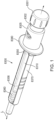
- the device includes a knob.
- the knob may include any suitable material, including that referred to above in connection with the rod.
- the knob is disposed at a proximal end of the device.
- the knob is attached to the rod.
- the knob is rotatable about the axis.
- the knob may have a cross-section transverse to the axis.
- the cross-section may be circular.
- the cross-section may be elliptical.
- the cross-section may be of any suitable shape. Any suitable shape may include a polygonal shape.
- the cross-section may be bordered by a perimeter.
- the knob may include turn ridges along the perimeter.
- the turn ridges may facilitate traction on the knob.
- the turn ridges may facilitate gripping the knob.
- the turn ridges may facilitate turning the knob.
- the knob may include a proximal end of the knob.
- the proximal end may include push features.
- the push features may facilitate pushing the rod.
- the push features may facilitate traction on the knob.
- the push features may include a push pad.
- the push pad may be smoothly contoured.
- the push features may include push ridges.
- the push ridges may be concentric about the axis.
- the guide may support the boss.
- the boss may be of a shape that is, at least in part, cylindrical, cubic, pyramidal, tetrahedral, ellipsoidal, hemispherical or any other suitable shape. Any other suitable shape may include prismatic. Any other suitable shape may include an irregular form of any of the listed shapes. Any other suitable shape may include a truncated form of any of the listed shapes. Any other suitable shape may include a combination of two or more of any of the listed shapes. The combination may include dome-capped cylindrical. The combination may include rounded-apex stepped tetrahedral.
- the device may include a housing.
- the housing may be disposed coaxial with the longitudinal axis.
- the housing may be disposed, relative to the longitudinal axis, distal-to-proximal parallel to the device.
- the housing may define an opening.
- the opening may be disposed proximally on the housing.
- the opening may be a proximal housing opening.
- the guide may be disposed in the proximal housing opening.
- the guide may be part of the housing.
- the guide may be manufactured as part of the housing.
- Manufacture of the guide as part of the housing may be accomplished through a molding process.
- Manufacture of the guide as part of the housing may be accomplished through an injection molding process.
- Manufacture of the guide as part of the housing may be accomplished through an overmolding process.
- the manufacture of the guide as part of the housing may be accomplished through a coinjection process.
- the guide may be separate from the housing.
- the guide may be manufactured separately from the housing.
- the guide may be molded separately from the housing.
- the guide may be affixed to the housing.
- the guide may include guide-anchoring elements.
- the housing may include guide-anchor-accepting elements structurally complementary to the guide-anchoring elements.
- the guide may be affixed to the housing by mating the guide-anchoring elements with the guide-anchoring-accepting elements.
- the device may include a medicament container.
- the container may be disposed in the housing.
- the container may be disposed distal the guide.
- the container may define a bore.
- the bore may be bound by an interior wall.
- the interior wall may define a substantially uniform diameter along a segment of the interior wall.
- the rod may be configured to be displaced distally, relative to the housing, within the bore to discharge medicament from the container.
- the rod may be displaced distally until the boss abuts the terminal surface of the track.
- the track may include the terminal surface.
- the track may support the terminal surface.
- the track may support the terminal surface proximally to the trigger.
- the terminal surface may be a distal surface of a proximal end-wall of the track.
- the end-wall may be a sidewall of the track.
- the end-wall may be orthogonal to the side of the track.
- the end-wall may be orthogonal to the running surface of the track.
- the end-wall may block relative proximal movement, beyond the distal surface of the end-wall, of the boss along the track.
- Abutment of the boss against the terminal surface may substantially limit motion of the rod in a distal direction.
- the track may include sidewalls. The sidewalls adjacent the terminal surface may substantially limit motion of the rod in a distal direction when the boss abuts the terminal surface. Track sidewalls adjacent to the terminal surface may substantially limit motion of the rod in a circumferential direction when the boss abuts the terminal surface. Track sidewalls distal to the terminal surface may substantially limit motion of the rod in a distal direction when the boss abuts the terminal surface. Track sidewalls distal to the terminal surface may substantially limit motion of the rod in a circumferential direction when the boss abuts the terminal surface.
- Abutment of the boss against the terminal surface may substantially limit motion of the rod, subsequent to the abutting, to movement in a proximal direction away from the boss.
- the boss abutting the terminal surface may limit motion of the boss, relative to the rod, to movement substantially axially away from the terminal surface.
- the segment of the interior wall may include a distal portion.
- the distal portion may, in operation of the device, contact a bulk liquid residuum of the medicament after the boss abuts the terminal surface.
- the distal portion may be wetted by the bulk liquid residuum even after the boss abuts the terminal surface.
- the distal portion may directly contact the residuum.
- the distal portion may directly contact the residuum even after the boss abuts the terminal surface.
- the device may include the plunger.
- the plunger may be at least one plunger slideably sealing against the interior wall.
- the plunger may be disposed within the container.
- the plunger may be disposed distal the rod.
- the plunger may be configured to slide distally responsive to distal displacement of the rod.
- the device may include the stopper.
- the stopper may seal a distal end of the container.
- the distal end of the container may define a distal container opening.
- a proximal body-section of the distal stopper may be disposed within the distal container opening.
- the proximal body section of the distal stopper may seal against the interior wall of the container proximal to the distal container opening.
- the stopper may include a distal surface.
- the distal surface may be disposed transverse to the axis.
- a distal body-section of the stopper proximal to the distal surface of the stopper may have an outer diameter greater than an outer diameter of the distal end of the container.
- a proximal rim of the distal body-section of the stopper may seal against an end-wall of the container surrounding the distal container opening.
- the housing may include a distal retaining ridge.
- the distal retaining ridge may be disposed transverse to the axis.
- the distal retaining ridge may be part of an interior of a wall of the housing.
- the distal retaining ridge may be proximal to a distal end-wall of the housing surrounding a distal opening of the housing.
- the distal opening of the housing may be a distal housing opening.
- the distal housing opening may have an inner diameter.
- the inner diameter of the distal housing opening may be smaller than an outer diameter of the distal body-section of the distal stopper.
- the outer diameter of the distal body-section of the distal stopper may be substantially the same as an outer diameter of the container.
- the outer diameter of the container may be smaller than an inner diameter of the housing proximal to the distal retaining ridge.
- the container, with the distal end of the container sealed by the distal stopper, may be disposed within the housing between a distal aspect of the guide and the distal retaining ridge.
- the medicament Prior to discharge of the medicament, the medicament may be sealed within the container between the stopper and the at least one plunger.
- the stopper may be configured to be penetrated by a needle.
- the needle may have a cannula.
- the cannula may be configured to distally transfer medicament discharged from the container.
- the cannula may be configured to transfer medicament directly through the needle to the patient.
- the cannula may be configured to transfer medicament indirectly through the needle to the patient.
- the needle may be a first needle.
- the device may include a second needle.
- the cannula of the first needle may be configured to transfer medicament to the second needle.
- the second needle may be configured to transfer medicament directly to the patient.
- the device may include a filter.
- the filter may be an in-line filter.
- the filter may be disposed between the first needle and the second needle.
- the filter may receive medicament discharged from the cannula of the first needle.
- the filter may filter medicament discharged from the cannula of the first needle.
- the second needle may receive medicament filtered by the filter.
- the second needle may transfer the medicament filtered by the filter to the patient.
- the medicament may include a formulation of one or more compounds.
- the compounds may include naturally occurring substances.
- the compounds may include substances derived from naturally occurring substances.
- the compounds may include synthetically produced substances.
- the compounds may include chimeric substances.
- the compounds may include engineered substances.
- the compounds may include humanized substances.
- the compounds may include substances produced by recombinant techniques.
- the compounds may include substances modified by recombinant techniques.
- the compounds may include a drug accepted for therapeutic treatment of a patient.
- the compounds may include a substance used in a therapeutic protocol.
- the compounds may include a substance used in a diagnostic protocol.
- the compounds may include a substance used in an experimental protocol.
- the compounds may include a substance compatible for use with apparatus and methods of the invention.
- the medicament may include any medical agent listed herein, either alone or in combination with one or more other listed medical agents or with one or more other, non-listed, medical agents.
- the medical agents may include anti-glaucoma medications, other ocular agents, neuroprotective agents, antimicrobial agents, anti-inflammatory agents (including steroids and non-steroidal compounds), and biological agents including hormones, enzymes or enzyme-related components, antibodies or antibody-related components, oligonucleotides (including DNA, RNA, short-interfering RNA, and other suitable oligonucleotides, such as antisense oligonucleotides), DNA/RNA vectors, viruses or viral vectors, peptides, and proteins.
- the medical agents may include anti-angiogenesis agents, including angiostatin, anecortave acetate, thrombospondin, vascular endothelial growth factor (VEGF) receptor tyrosine kinase inhibitors, and anti-VEGF drugs, such as ranibizumab (LUCENTIS°), bevacizumab (AVASTIN ® ), pegaptanib (MACUGEN ® ), sunitinib, and sorafenib, and any of a variety of known small-molecule and transcription inhibitors having an anti-angiogenesis effect; ophthalmic drugs, including glaucoma agents, such as adrenergic antagonists, including beta-blocker agents such as atenolol, propranolol, metipranolol, betaxolol, carteolol, levobetaxolol, levobunolol and timolol.
- anti-angiogenesis agents including angiostatin,
- the medical agents may include platelet-derived growth factor (PDGF) inhibitors and anti-PDGF drugs.
- the medical agents may include transformation growth factor (TGF) inhibitors and anti-TGF drugs.
- the medical agents may include anti-inflammatory agents including glucocorticoids and corticosteroids, such as betamethasone, cortisone, dexamethasone, dexamethasone 21-phosphate, methylprednisolone, prednisolone 21-phosphate, prednisolone acetate, prednisolone, loteprednol, medrysone, fluocinolone acetonide, triamcinolone acetonide, triamcinolone, beclomethasone, budesonide, flunisolide, fluorometholone, fluticasone, hydrocortisone, hydrocortisone acetate and rimexolone; and non-steroidal anti-inflammatory agents including diclofenac, flurbiprof
- the medical agents may include anti-cytokine agents; the medical agents may include anti-interleukin-6 agents such as tocilizumab (ACTEMRA ® ).
- the medical agents may include anti-complement agents, including those targeting complement factor D (such as an anti-complement factor D antibody or an antigen-binding fragment thereof) such as lampalizumab, and those targeting complement factor H (such as an anti-complement factor H antibody or an antigen-binding fragment thereof).
- the medical agents may include angiopoietin-specific agents, such as an angiopoietin-2 antibody or an antigen-binding fragment thereof.
- the medical agents may include human growth hormone.
- the medical agents may include any suitable medical agent.
- the medicament may include one or more derivatives of any of the above-mentioned medical agents.
- the medicament may include advanced forms of any of the above-mentioned medical agents.
- the medicament may include mutated forms of any of the above-mentioned medical agents.
- the medicament may include combinations of any of the above-mentioned medical agents. The combinations may be incorporated into a multi-specific molecule.
- the multi-specific molecule may exhibit properties of its constituent parts.
- the multi-specific molecule may exhibit properties different from any if its constituent parts.
- the medicament may include depots, hydrogels and pegylated forms of any of the above medical agents.
- the medicament may include any suitable form of any of the above medical agents.
- the medicament Prior to discharge of the medicament, the medicament may be stored within the container.
- the medicament may be stored in a dischargeable form of the medicament.
- the dischargeable form of the medicament may include all medical agents desired in a scenario - therapeutic, experimental or otherwise - for delivery, under desired conditions. Desired conditions may include therapeutic activity, medical agent concentration(s), viscosity, pH, ionic strength or any other suitable condition.
- the medicament may be stored in a storage form of the medicament.
- the storage form of the medicament may require preparation of the medicament for discharge.
- the preparation of the medicament for discharge may include conversion of the medicament from the storage form of the medicament to the dischargeable form of the medicament.
- the storage form of the medicament may include a first component.
- the first component may be stored in the medicament container.
- the storage form of the medicament may include a second component.
- the second component may be stored in the medicament container.
- the second component may be stored apart from the first component.
- the first component may be a formulation of any of the above-mentioned medical agents.
- the second component may be a formulation of any of the above-mentioned medical agents.
- the first component may be a formulation that, upon mixing with the second component, adjusts conditions of the second component.
- the second component may be a formulation that, upon mixing with the first component, adjusts conditions of the first component.
- Conditions may include therapeutic activity, medical agent concentration(s), viscosity, pH and ionic strength.
- the preparation of the medicament may include mixing the first component and the second component.
- a mixture of the first component and the second component may include the dischargeable form of the medicament.
- the storage form of the medicament may include a lyophilized product that, when reconstituted, includes the dischargeable form of the medicament.
- Reconstitution of the lyophilized product may involve mixing the lyophilized product with a reconstituting solution.
- the lyophilized product may be the first component.
- the reconstituting solution may be the second component.
- the second component may be in a liquid state.
- the device may include a rod-contacting face.
- the distal end of the rod may contact the rod-contacting face.
- the distal end of the rod may connect with the rod-contacting face.
- the distal end of the rod may couple with the rod-contacting face.
- the rod-contacting face may be distally displaced within the container in response to distal displacement of the rod within the container.
- the at least one plunger may include a proximal plunger.
- the rod-contacting face may be associated with a proximal face of the proximal plunger.
- the proximal face of the proximal plunger may include the rod-contacting face.
- the proximal plunger may be distally displaced within the container in response to distal displacement of the rod-contacting face within the container.
- the proximal plunger may be distally displaced within the container in response to distal displacement of the rod within the container.
- the at least one plunger may include a discharge plunger.
- the discharge plunger may be disposed within the container distal to the proximal plunger. There may be no other plunger within the container between the discharge plunger and the stopper.
- the first component and the second component Prior to the mixing of the first component and the second component, the first component and the second component may be separated by the discharge plunger.
- the first component may be sealed within the container between the stopper and the discharge plunger.
- the second component may be sealed within the container between the discharge plunger and the proximal plunger.
- the container may include a bypass feature.
- the bypass feature may be configured to facilitate fluid communication bypassing a sealing surface of the discharge plunger.
- the bypass feature may include one or more grooves, at least partly longitudinal with respect to the axis, recessed into the interior wall. Prior to mixing, the sealing surface of the discharge plunger may be disposed proximal to a proximal-most aspect of the bypass feature, sealing against the interior wall and maintaining the second component apart from the first component.
- the mixing may involve orienting the device with its distal end up and penetrating the stopper to dispose the cannula through the stopper.
- the mixing may involve distal displacement of the rod-connecting face via distal displacement of the rod. Distal displacement of the rod-connecting face may distally displace the proximal plunger. Distal displacement of the proximal plunger may distally displace the second component. Distal displacement of the second component may distally displace the discharge plunger.
- Distal displacement of the discharge plunger may slide a proximal-most circumferential portion of the sealing surface of the discharge plunger along the interior wall to a position just distal to the proximal-most aspect of the bypass feature, facilitating distal flow along the bypass feature of the second component into the first component. Further distal displacement of the proximal plunger may not substantially displace the discharge plunger while the second component remains between the proximal plunger and the discharge plunger. While the second component remains between the proximal plunger and the discharge plunger, distal displacement of the proximal plunger may distally displace the second component along the bypass feature, facilitating mixing of the second component with the first component.
- a distal face of the proximal plunger may be complementary to a proximal face of the discharge plunger.
- substantially no second component may remain between the proximal plunger and the discharge plunger.
- the mixture may include the dischargeable form of the medicament.
- further distal displacement of the proximal plunger may further distally displace the discharge plunger.
- a distal face of the discharge plunger may, upon being distally displaced toward the stopper, distally displace the dischargeable form of the medicament.
- a scenario in which the medicament is stored during device manufacture in the storage form may be accommodated by a configuration of the device in which the at least one plunger includes the proximal plunger and the discharge plunger and in which the container includes the bypass feature.
- a configuration of the device may be termed a mixing configuration.
- the rod-contacting face may be associated with the proximal plunger.
- a scenario in which the medicament is stored during device manufacture in the dischargeable form may require, in the container, neither multiple plungers for sequestration of storage form components nor the bypass feature for mixing of components.
- the plunger may include only the discharge plunger.
- a configuration of the device in which the plunger is the discharge plunger and in which the interior wall does not include the bypass feature, may be termed a non-mixing configuration.
- the rod-connecting face may be associated with the discharge plunger.
- the rod-contacting face may be associated with a proximal face of the discharge plunger.
- the proximal face of the discharge plunger may include the rod-contacting face.
- the discharge plunger may be distally displaced by distal displacement of the plunger rod contacting the proximal face of the discharge plunger.
- the device may be manufactured as a "pre-filled" device.
- the device may be manufactured with the container configured to store the predetermined low volume of the medicament.
- the volume may be substantially determined during manufacture.
- the volume may be set with anticipation of loss of medicament that may result from manipulations of the device prior to performance of the delivery stroke. Such manipulations may include mixing and priming.
- the volume may depend on the scenario for which the device is intended.
- Illustrative ranges of value of the volume may include about 0.025 milliliter to about 0.05 milliliter, about 0.05 milliliter to about 0.1 milliliter, about 0.1 milliliter to about 0.25 milliliter, about 0.25 milliliter to about 0.5 milliliter, about 0.5 milliliter to about 1 milliliter, about 1 milliliter to about 2 milliliters, about 2 milliliters to about 3 milliliters, about 3 milliliters to about 4 milliliters, about 4 milliliters to about 5 milliliters, about 5 milliliters to about 6 milliliters, about 6 milliliters to about 7 milliliters, about 7 milliliters to about 8 milliliters, about 8 milliliters to about 9 milliliters, about 9 milliliters to about 10 milliliters, or any other suitable ranges.
- the housing may include a housing wall.
- the housing wall may be configured to deflect in response to deflection of the guide.
- the housing wall may include a section that is displaced radially relative to the longitudinal axis during the deflection of the guide.
- the section may be a first section.
- the housing wall may include a second section that is displaced radially relative to the longitudinal axis during the deflection of the guide. Radial direction of displacement of the section or sections relative to the longitudinal axis may conform to radial direction of the deflection of the guide relative to the longitudinal axis.
- the displacement of the section or sections may be radially outward.
- the displacement of the section(s) may be radially inward.
- the device may include a finger flange.
- the finger flange may be part of the housing.
- the finger flange may be manufactured as part of the housing.
- Manufacture of the finger flange as part of the housing may be accomplished through a molding process.
- Manufacture of the finger flange as part of the housing may be accomplished through an injection molding process.
- Manufacture of the finger flange as part of the housing may be accomplished through an overmolding process.
- the manufacture of the finger flange as part of the housing may be accomplished through a coinjection process.
- the finger flange may be separate from the housing.
- the finger flange may be manufactured separately from the housing.
- the finger flange may be molded separately from the housing.
- the finger flange may be affixed to the housing.
- the finger flange may have finger flange-anchoring elements.
- the housing may have finger flange-anchor-accepting elements structurally complementary to the finger flange-anchoring elements.
- the finger flange may be affixed to the housing by mating the finger flange-anchoring elements with the finger flange-anchoring-accepting elements.
- the delivery stroke may be predetermined during the manufacture of the device. Mechanical properties of the materials of, and manufactured configuration of, the container and its associated stopper and plunger(s) and of the housing, guide and rod, may determine the delivery stroke. The full extent of the delivery stroke may be predetermined in manufacturing.
- the method of manufacturing includes providing the rod.
- Providing the rod may include molding the rod.
- the rod may be configured to be displaced within the housing toward a distal end of the housing.
- the rod may support a terminal surface, such that, with the boss engaging the rod at the track and with the boss abutting the terminal surface, the boss may provide a reactive surface that limits further distal displacement of the rod.
- movement of the boss relative to the rod may be limited to substantially axial movement away from the terminal surface.
- the boss With the boss engaging a longitudinal tract of the track, the boss may provide a reactive surface that limits rotational movement of the rod about the axis.
- the boss may engage the track by extending radially into the track.
- the boss may be engaged with the longitudinal tract by extending radially into the longitudinal tract.
- the materials may be elected for their material properties.
- the material properties for which the materials may be elected may facilitate operation of the device.
- Material properties that facilitate operation of the device may include chemical inertness, resilience, transparency and other suitable properties. Other suitable properties may include hardness.
- the plunger or plungers may include a plunger material.
- the plunger material may include polymeric material.
- the plunger material may include elastomeric material.
- the plunger material may include thermoplastic elastomer (TPE).
- TPE thermoplastic elastomer
- the plunger material may include natural rubber.
- the plunger material may include a compound made from natural rubber.
- the plunger material may include synthetic rubber.
- the plunger material may include a compound made from synthetic rubber.
- the plunger material may include silicone rubber.
- the plunger material may include a compound made from silicone rubber.
- the plunger material may include butyl rubber.
- the plunger material may include a compound made from butyl rubber.
- the plunger material may include a material elected to reduce interaction of the plunger or plungers with the medicament.
- the plunger material may include a resilient material.
- the plunger material may include a material with a hardness less than about 80 Shore A durometer (ASTM D2240 type A hardness scale).
- the plunger material may facilitate movement of the plunger or plungers within the container.
- the plunger material may facilitate engagement of the plunger or plungers with the inner wall of the container.
- the plunger material may facilitate sealing of the plunger or plungers against the inner wall of the container.
- the plunger material may include a plunger lubricious coating.
- the plunger lubricious coating may coat the plunger material.
- the plunger material may bear the plunger lubricious material.
- the plunger lubricious material may include polytetrafluoroethylene (PTFE).
- the plunger lubricious material may include ethylene tetrafluoroethylene (ETFE).
- the plunger lubricious coating may include a material elected to reduce interaction of the plunger or plungers with the medicament.
- the plunger lubricious material may facilitate movement of the plunger or plungers within the container.
- the plunger lubricious material may facilitate engagement of the plunger or plungers with the inner wall of the container.
- the plunger lubricious material may facilitate sealing of the plunger or plungers against the inner wall of the container.
- the guide may include a guide material.
- the guide material may include polymeric material.
- the guide material may include thermoplastic polymer.
- the guide material may include delrin.
- the guide material may include polypropylene.
- the guide material may include nylon.
- the guide material may include teflon.
- the guide material may include acrylonitrile butadiene styrene (ABS).
- the guide material may include polycarbonate.
- the guide material may include polysulfone.
- the guide material may include acrylic polymer.
- the guide material may include polymethylmethacrylate (PMMA).
- the guide material may include a stiff material.
- the guide material may include a material with a hardness more than about 80 Shore A durometer.
- the guide material may include a material with a low coefficient of friction.
- the guide material may include a material with a coefficient of friction of about 0.01 to about 0.5.
- the rod may include a rod material.
- the rod material may include polymeric material.
- the rod material may include thermoplastic polymer.
- the rod material may include delrin.
- the rod material may include polypropylene.
- the rod material may include nylon.
- the rod material may include teflon.
- the rod material may include ABS.
- the rod material may include polycarbonate.
- the rod material may include polysulfone.
- the rod material may include acrylic polymer.
- the rod material may include PMMA.
- the rod material may include a stiff material.
- the rod material may include a material with a hardness more than about 80 Shore A durometer.
- the rod material may include a material with a low coefficient of friction.
- the rod material may include a material with a coefficient of friction of about 0.01 to about 0.5.
- the housing may include a housing material.
- the housing material may include polymeric material.
- the housing material may include thermoplastic polymer.
- the housing material may include delrin.
- the housing material may include polypropylene.
- the housing material may include nylon.
- the housing material may include teflon.
- the housing material may include ABS.
- the housing material may include polycarbonate.
- the housing material may include polysulfone.
- the housing material may include acrylic polymer.
- the housing material may include PMMA.
- the housing material may include a stiff material.
- the housing material may include a material with a hardness more than about 80 Shore A durometer.
- the housing material may include a material with a low coefficient of friction.
- the housing material may include a material with a coefficient of friction of about 0.01 to about 0.5.
- the housing material may include a material that is translucent.
- the housing material may include a material that is transparent.
- the container may include a container material.
- the container material may include polymeric material.
- the plunger material may include amorphous material.
- the container material may include thermoplastic polymer.
- the container material may include glass.
- the container material may include type 1 borosilicate glass.
- the container material may include cyclic olefin copolymer (COC).
- the container material may include polypropylene.
- the container material may include PMMA.
- the container material may include a material that is translucent.
- the container material may include a material that is transparent.
- the container material may include a container lubricious coating.
- the container lubricious coating may coat the container material.
- the container material may bear the container lubricious material.
- the container lubricious coating may include silicone oil. The container lubricious material may facilitate movement of the plunger or plungers within the container.
- some embodiments may feature an ABS plunger rod disposed in a passageway of a delrin guide affixed to a PMMA housing.
- the embodiments may feature, in a borosilicate glass container, silicone rubber plungers with PTFE coatings and a butyl rubber stopper with an ETFE coating.
- the embodiments may feature ABS trigger protrusions integral to the ABS rod, the protrusions supported by parallel helicoidal tracts of parallel helix-containing tracks of the mixing configuration.
- the embodiments may feature ABS end-walls of parallel longitudinal tracts of the helix-containing tracks, the end-walls serving as terminal surfaces of the helix-containing tracks.
- the embodiments may feature delrin bosses integral to the delrin guide, the delrin bosses of truncated pyramidal shape and oriented within the guide in conformity with a helical pitch of the helicoidal tracts of the tracks.
- Some embodiments may feature any other suitable combination of materials and/or geometries.
- the device may include determination of the extent of the delivery stroke by abutment of the rod material with the guide material, the guide material fixed in place axially and rotationally relative to the housing.
- the greater hardness of rod material, guide material and housing material compared to the plunger material and the stopper material may provide a greater reliability of low volume delivery through abutment of the boss against the terminal surface than provided by bottoming out a typical syringe plunger against a distal inner end of a typical syringe.
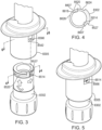
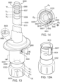
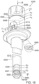
- the device includes a collar.
- the collar may include any suitable material, including that referred to above in connection with the guide.
- the collar is disposed coaxial with the longitudinal axis.
- the collar includes a projection.
- the device includes the plunger rod.
- the plunger rod is threadingly engaged, coaxially within the collar, with the proximal knob.
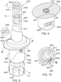
- the proximal knob includes a track.
- the track may include an annular tract.
- the track may include a longitudinal tract.
- the boss may slidingly engage the annular tract to longitudinally retain the knob during a rotation of the knob about the axis.
- the boss may slidingly engage the longitudinal tract during a longitudinal translation of the knob.
- the projection slidingly engages a longitudinally extending structure of the rod to rotationally retain the rod during the rotation. The rotation may drive the rod toward the distal end.
- the translation may be delimited by interference between the boss and a proximal terminal surface of the longitudinal tract.
- the translation may advance the target amount out of the distal end.
- the longitudinal tract may intersect the annular tract.
- the rotation may be delimited by abutment of the boss against a lateral surface of the longitudinal tract.
- the longitudinal tract may retain the knob rotationally during the translation and may corresponds, in longitudinal extent, from the location of the abutment, to the target amount.
- the interference may limit motion of the boss, relative to the knob, to motion that is directed away from the terminal surface and parallel to the axis. The interference may terminate advancement of medicament out of the distal end.
- the collar may include a bracket configured to retain, coaxially with the knob, a medicament container.
- the container may define a bore bound by an interior sidewall that defines, along a segment of the sidewall, a uniform diameter.
- a distal end of the rod may abut a plunger within the container.
- the plunger may be slidingly engaged with the sidewall.
- the plunger Before the translation, the plunger may seal a pre-delivery amount of the medicament between an inner distal end-wall of the container and the plunger. After the translation, a distal portion of the segment may contact a bulk liquid residuum contained between the inner distal end-wall and the plunger.
- the amount of the medicament in the residuum may be an amount that is no greater than the pre-delivery amount less the target amount.
- the rotation may set the pre-delivery amount.
- the rotation may prepare the medicament for delivery.
- the preparation may include mixing components of the medicament within the container.
- the plunger may be the first plunger and, distal to the first plunger, the second plunger may slidingly engage with the segment.
- a liquid component of the medicament may be sealed within the container between the first plunger and the second plunger.
- the mixing may include transfer of the liquid component, within the container, distally past the second plunger. After the mixing, the distal face of the first plunger may abut the proximal face of the second plunger.
- the preparing may include priming the container.
- the priming may include the distal discharge of air from the container.
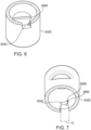
- the knob may include signage.
- the signage may provide an indication of a stage of device operation.
- the collar may define a window.
- the window may expose a portion of the signage.
- the portion may indicate, prior to the rotation, a medicament preparation stage of the device operation.
- the portion may indicate, during the rotation, continuation of the preparation stage.
- the portion may indicate, after the rotation, a medicament delivery stage of the device operation.
- the portion may indicate, after the rotation and prior to the translation, commencement of the delivery stage.
- the portion may indicate, after the translation, completion of the delivery stage.
- the abutment may provide tactile indication of completion of a medicament preparation stage of device operation.
- the abutment may provide acoustic indication of completion of a medicament preparation stage of device operation.
- the interference may provide an indication of completion of a medicament delivery stage of device operation.
- the longitudinally extending structure may extend along a length of the rod that is disposed between a proximal thread of the rod and a distal end of the rod.
- the longitudinally extending structure may support a surface feature configured to interfere with the projection to longitudinally retain the rod from proximal movement.
- the surface feature may have a proximal stop surface.
- the proximal stop surface may provide blockage against distal movement of the projection relative to the surface feature.
- Distal to the stop surface the surface feature may provide passage for proximal movement of the projection relative to the surface feature.
- the projection projects radially inward.
- the projection may have a distal stop surface.
- the distal stop surface may provide blockage against distal movement of the projection relative to the surface feature.
- Proximal to the stop surface the projection may provide passage for proximal movement of the projection relative to the surface feature.
- the longitudinally extending structure may include a slot.
- the slot may extend radially inward.
- the surface feature may extend, in a plane transverse to the axis, into the slot.
- the longitudinally extending structure may include a rail.
- the rail may extend radially outward.
- the surface feature may extend, in a plane transverse to the axis, radially outward from the rail.
- the boss may include a flexible panel.
- the flexible panel may include a free end.
- the free end may be disposed more radially inward than any other surface of the boss.
- the free end may be disposed more radially inward than any other part of the boss.
- a running surface of the track may support a trigger.
- the free end may be configured to, responsive to interaction between the free end and the trigger, deflect relative to the axis when the panel passes by the trigger.
- the trigger may have a stop surface.
- the stop surface may be disposed on a plane transverse to the axis.
- the stop surface may be configured to block passage of the free end in a direction opposite to the rotation.
- the trigger may include the protrusion.
- the interaction may involve an interference between the free end and the trigger.
- the panel may pass by the stop surface after passing by all other surfaces of the trigger.
- the trigger may include a recess.
- the interaction may include an urging of the free end against the recess.
- the panel may pass by the stop surface before passing by any other surface of the trigger.
- the interaction may occur upon initiation of the rotation.
- the boss Prior to the interaction, the boss may be disposed adjacent a portion of the annular tract that is circumferentially most distant, in the direction of the rotation, from the longitudinal tract. Prior to the interaction, the trigger may limit motion of the free end along the track.
- the interaction may occur upon completion of the rotation.
- the trigger may be disposed on the annular tract at a juncture of the annular tract and the longitudinal tract.
- the trigger following the interaction, may limit rotary motion of the knob in a direction opposite the rotation.
- the deflection may provide an indication of the interaction.
- the indication may be tactile.
- the indication may be acoustic.
- the device includes the collar.
- the collar is disposed coaxial with the axis.
- the collar supports a flexible panel and a projection.
- the device includes the plunger rod.
- the plunger rod is threadingly engaged, coaxially within the collar, with the proximal knob.
- the proximal knob includes the track that supports the trigger.
- the panel is configured to deflect, responsive to interaction with the trigger, relative to the axis.
- the panel slidingly engages the track to longitudinally retain the knob during a rotation of the knob about the axis.
- the rod includes a longitudinally extending structure.
- the projection slidingly engages the longitudinally extending structure to rotationally retain the rod during the rotation. The rotation drives the rod toward the distal end.
- the track may include the annular tract.
- the track may include the longitudinal tract.
- the annular tract may intersect the longitudinal tract.
- the panel may slidingly engage the annular tract during the rotation.
- the panel may slidingly engage the longitudinal tract during a longitudinal translation of the knob.
- the longitudinal tract may retain the knob rotationally during the translation and may correspond, in longitudinal extent, from the intersecting, to the target amount.
- the translation may be delimited by interference between the panel and the proximal terminal surface of the longitudinal tract.
- the interference may limit motion of the panel, relative to the knob, to motion that is directed away from the terminal surface and parallel to the axis.
- the interference may terminate advancement of medicament out of the distal end.
- the collar may support the bracket.
- the bracket may be configured to retain, coaxially with the knob, the medicament container.
- the container may define a bore bound by an interior sidewall that defines, along a segment of the sidewall, a uniform diameter.
- the distal end of the rod may abut the plunger within the container.
- the plunger may be slidingly engaged with the sidewall. Before the translation, the plunger may seal the pre-delivery amount of the medicament between the inner distal end-wall of the container and the plunger. After the translation, the distal portion of the segment may contact the bulk liquid residuum contained between the inner distal end-wall and the plunger.
- the amount of the medicament in the residuum may be an amount that is no greater than the pre-delivery amount less the target amount.
- the distal portion of the segment may directly contact the residuum.
- the rotation may set the pre-delivery amount.
- the rotation may prepare the medicament for delivery.
- the preparing may include priming the container.
- the priming may include distal discharge of air from the container.
- the priming may include distal discharge of an inert gas from the container.
- the knob may include the signage.
- the signage may provide the indication.
- the indication may be an indication of a stage of device operation.
- the collar may define the window.
- the window may expose the portion of the signage.
- the portion may indicate, prior to the rotation, the medicament preparation stage of the device operation.
- the portion may indicate, after the rotation, the medicament delivery stage of the device operation.
- the portion may indicate, during the rotation, continuation of the preparation stage.
- the portion may indicate, after the rotation and prior to the translation, commencement of the delivery stage.
- the portion may indicate, after the translation, completion of the delivery stage.
- the longitudinally extending structure may extend along a length that is disposed between a proximal thread of the rod and a distal end of the rod.
- the longitudinally extending structure may support the surface feature configured to interfere with the projection to longitudinally retain the rod from proximal movement.
- the surface feature may include a proximal stop surface.
- the proximal stop surface may provide blockage against distal movement of the projection relative to the surface feature.
- Distal to the stop surface the surface feature may provide passage for proximal movement of the projection relative to the surface feature.
- the projection may project radially inward.
- the projection may include the distal stop surface.
- the distal stop surface may provide blockage against distal movement of the projection relative to the surface feature.
- Proximal to the stop surface the projection may provide passage for proximal movement of the projection relative to the surface feature.
- the longitudinally extending structure may include the slot that extends radially inward.
- the surface feature may extend, in the plane transverse to the axis, into the slot.
- the longitudinally extending structure may include the rail that extends radially outward.
- the surface feature may extend, in the plane transverse to the axis, out from the rail.
- the panel may be supported by the boss that is supported by the collar.
- the boss In the rotation, the boss may be in sliding engagement with the annular tract.
- the panel In the rotation, the panel may trail all other surfaces of the boss. In the rotation, the panel may trail all other parts of the boss.
- the panel may include the free end. The free end may be disposed more radially inward than any other surface of the panel. The free end may be disposed more radially inward than any other part of the panel.
- the free end may trail all other surfaces of the panel. In the rotation, the free end may trail all other parts of the panel.
- the running surface of the track may support the trigger.
- the free end may interact with the trigger to produce the deflection when the panel passes by the trigger.
- the trigger may include the stop surface.
- the stop surface may be disposed on the plane transverse to the axis.
- the stop surface may be configured to block passage of the free end in a direction opposite to the rotation.
- the trigger may include the protrusion.
- the interaction may be an interference between the free end and the trigger.
- the panel may pass by the stop surface after passing by all other surfaces of the trigger.
- the panel may pass by the stop surface after passing by all other parts of the trigger.
- the trigger may include a recess.
- the interaction may include urging the free end against the recess.
- the panel may pass by the stop surface before passing by any other surface of the trigger.
- the panel may pass by the stop surface before passing by any other part of the trigger.
- the interaction may occur upon initiation of the rotation.
- the boss Prior to the interaction, the boss may be disposed adjacent a portion of the annular tract that is circumferentially most distant, in the direction of the rotation, from the longitudinal tract.
- the trigger Prior to the interaction, the trigger may limit motion of the free end along the track.
- the interaction may occur upon completion of the rotation.
- the trigger may be disposed on the annular tract at a juncture of the annular tract and the longitudinal tract. Following the interaction, the trigger may limit rotary motion of the knob in a direction opposite the rotation.
- the panel may be circumferentially aligned with the longitudinal tract.
- the deflection may provide the indication of the interaction.
- the indication may be tactile.
- the indication may be acoustic.
- the longitudinal tract may include a lateral surface.
- the rotation may be delimited by abutment of the boss against the lateral surface.
- the abutment may circumferentially align the boss with the longitudinal tract.
- the abutment may provide tactile indication of completion of the medicament preparation stage of device operation.
- the abutment may provide acoustic indication of completion of the medicament preparation stage of device operation.
- the interference may provide indication of completion of the medicament delivery stage of device operation.
- the method is a method of manufacturing a medicament delivery device.
- the method includes providing the knob having the annular recess that includes the surface from which extends the protrusion.
- the method includes providing the collar that supports the flexible panel that extends into an interior of the collar.
- the method includes positioning the knob coaxially within the collar so that a free end of the panel extends radially inward beyond the protrusion and is deflectable by the protrusion when the knob rotates relative to the collar.
- the method includes threadingly engaging the plunger rod with the knob.
- the method includes securing the rod against rotation relative to the knob.
- the providing a knob may include providing a knob that has a longitudinal recess.
- the longitudinal recess may intersect the annular recess.
- the longitudinal recess may support the terminal surface configured to abut the panel.
- the providing a collar may include providing a collar that includes the projection.
- the securing may include engaging the projection with the longitudinally extending structure of the rod.
- the longitudinally extending structure may include the slot.
- the engaging may include insertion of the projection into the slot.
- the longitudinally extending structure may include the rail.
- the engaging may include positioning the projection alongside the rail.
- the methods may include providing a rod that includes an end supporting a thread that is engageable with the knob.
- the device includes the collar disposed coaxial with the axis.
- the collar includes the projection and the track.
- the track may include an annular tract and a longitudinal tract.
- the device includes the plunger rod.
- the plunger rod is threadingly engaged, coaxially within the collar, with the proximal knob.
- the proximal knob may include the boss.
- the boss may slidingly engage the annular tract to longitudinally retain the knob during a rotation of the knob about the axis.
- the boss may slidingly engage the longitudinal tract during a longitudinal translation of the knob.
- the projection may slidingly engage the longitudinally extending structure of the rod to rotationally retain the rod during the rotation.
- the rotation may drive the rod toward the distal end.
- the translation may be delimited by interference between the boss and the proximal terminal surface of the longitudinal tract. The translation may advance the target amount out of the distal end.
- the longitudinal tract may intersect the annular tract.
- the rotation may be delimited by abutment of the boss against the lateral surface of the longitudinal tract.
- the abutment may circumferentially align the boss with the longitudinal tract.
- the longitudinal tract may retain the knob rotationally during the translation and corresponds in longitudinal extent, from a location of the abutment, to the target amount
- the interference may limit motion of the boss, relative to the collar, to motion that is directed away from the terminal surface and parallel to the axis.
- the interference may terminate advancement of medicament out of the distal end.
- the collar may include the bracket.
- the bracket may be configured to retain, coaxially with the knob, a medicament container.
- the container may define a bore bound by an interior sidewall that defines, along a segment of the sidewall, a uniform diameter.
- the distal end of the rod may abut a plunger within the container.
- the plunger may be slidingly engaged with the sidewall.
- the plunger Before the translation, the plunger may seal a pre-delivery amount of the medicament between the inner distal end-wall of the container and the plunger. After the translation, a distal portion of the segment may contact the bulk liquid residuum contained between the inner distal end-wall and the plunger.
- the amount of the medicament in the residuum may be an amount that is no greater than the pre-delivery amount less the target amount.
- the rotation may set the pre-delivery amount.
- the rotation may prepare the medicament for delivery.
- the preparing may include mixing components of the medicament within the container.
- the preparing may include priming the container.
- the priming may include distal discharge of air from the container.
- the priming may include distal discharge of inert gas from the container.
- the knob may include signage that provides an indication of the stage of device operation.
- the collar may define the window exposing the portion of the signage.
- the portion may indicate, prior to the rotation, a medicament preparation stage of the device.
- the portion may indicate, after the rotation, a delivery stage of the device.
- the portion may indicate, during the rotation, continuation of the medicament preparation stage.
- the portion may indicate, after the rotation and prior to the translation, commencement of the delivery stage.
- the portion may indicate, after the translation, completion of the delivery stage.
- the abutment may provide tactile indication of completion of the medicament preparation stage.
- the abutment may provide acoustic indication of completion of the medicament preparation stage.
- the interference may provide the indication of completion of the medicament delivery stage of device operation.
- the longitudinally extending structure may include the slot that extends along a length that is disposed between the proximal thread of the rod and the distal end of the rod.
- the longitudinally extending structure may include a rail that extends along a length that is disposed between the proximal thread of the rod and the distal end of the rod.
- FIG. 1 shows illustrative medicament delivery device 8300.
- Delivery device 8300 defines longitudinal axis L. Delivery device 8300 is shown in a state that is a pre-operational state. In use of delivery device 8300, the pre-operational state precedes an operational state. In the pre-operational state, delivery device 8300 is fully assembled. In the pre-operational state, delivery device 8300 may be prepared for priming. In the pre-operational state, delivery device 8300 may be prepared for preparation of medicament for discharge. In the pre-operational state, delivery device 8300 may be prepared for discharge of medicament. In the pre-operational state, discharge of medicament from delivery device 8300 has not begun.
- Delivery device 8300 includes proximal knob 8302.
- Knob 8302 is disposed coaxial with axis L.
- Grip 8301 may be provided on knob 8302.
- Delivery device 8300 includes plunger rod 8310.
- Rod 8310 may be a component of a mixing configuration (not shown).
- Knob 8302 is threadingly attached to rod 8310.
- Delivery device 8300 may include medicament container 8350.
- Container 8350 may be a component of a mixing configuration (not shown).
- Container 8350 may be disposed coaxial with axis L.
- Container 8350 may be cylindrical, partially cylindrical or have any other suitable form.
- a distal portion of rod 8310 may be disposed within container 8350.
- Container 8350 may contain medicament component 8360.
- Container 8350 may be engaged with plunger 8356.
- a distal end of rod 8310 may abut a proximal surface of plunger 8356.
- Delivery device 8300 may include device housing 8370.
- Housing 8370 may be disposed coaxial with axis L.
- Housing 8370 may be cylindrical, partially cylindrical or have any other suitable form.
- Delivery device 8300 may include finger flange 8380.
- Finger flange 8380 may be separate from housing 8370.
- Finger flange 8380 may be attached to housing 8370.
- Finger flange 8380 may be integral to housing 8370.
- Delivery device 8300 includes collar 8305.
- Collar 8305 is disposed coaxial with axis L.
- Collar 8305 may be cylindrical, partially cylindrical or have any other suitable form.
- Collar 8305 may be attached to finger flange 8380.
- Collar 8305 may be integral to finger flange 8380.
- Collar 8305 may be attached to housing 8370.
- Collar 8305 may be integral to housing 8370.
- FIG. 2 shows features of delivery device 8300.
- FIG. 2 shows knob 8302.
- Knob 8302 contains threads 8492 (shown in phantom) internal to knob 8302.
- Grip 8301 may contribute to traction on knob 8302 for effecting longitudinal translation of rod 8310. Grip 8301 may contribute to ergonomic finger contact of the operator with knob 8302 for effecting longitudinal translation of rod 8310. The finger contact with knob 8302 through grip 8301 may conduct tactile feedback to the operator of an extent of distal longitudinal translation of rod 8310 along axis L.
- Knob 8302 may include turn ridges 8406.
- Turn ridges 8406 may be utilized by the operator to effect rotation of knob 8302 about axis L.
- Turn ridges 8406 may contribute to traction on knob 8302 for effecting translation of rod 8310.
- Turn ridges 8406 may contribute to ergonomic finger contact of the operator with knob 8302 for effecting translation of rod 8310 through rotation of knob 8302.
- the finger contact with turn ridges 8406 may conduct tactile feedback to the operator of an extent of translation of rod 8310 along axis L.
- Turn ridges 8406 may be spaced circumferentially around knob 8302. Turn ridges 8406 may be spaced regularly around a circumference of grip 8301. Turn ridges 8406 being spaced regularly about the circumference of grip 8301 may provide the operator a measure of an extent of rotation performed.
- Knob 8302 may include turn direction signage 8408.
- delivery device 8300 may effect distal displacement of rod 8310 within container 8350 in response to rotation of knob 8302 about axis L in only one of two rotational directions.
- Turn direction signage 8408 may provide the operator with cues as to an effective rotational direction.
- the cues may serve as reminders before and/or during the operational state.
- the cues may be visual.
- the cues may be tactile.
- the effective rotational direction for distal displacement of rod 8310 within container 8350 in response to rotation of knob 8302 about axis L may be clockwise for delivery device 8300.
- counter-clockwise rotation may the effective rotational direction.
- turn direction signage may provide cues for counter-clockwise rotation.
- Distal rod end 8411 may define a distal end of anti-rotation slot 8461.
- Anti-rotation slot 8461 may be parallel to axis L.
- Distal rod end 8411 may include one or more additional anti-rotation slots or features (not shown) distributed about the circumference of rod 8310 in a regular or irregular manner.
- Anti-rotation slot 8461 may extend all or some of the way proximally to threads 8462. Threads 8462 extend proximally some or all of the way to proximal rod end 8468. Threads 8462 engage threads 8492 of knob 8302.
- Rod 8310 may include flat face 8464.
- Flat face 8464 may be parallel to axis L.
- Rod 8310 may include one or more additional flat faces (not shown) distributed about the circumference of rod 8310 in a regular or irregular manner.
- Flat face 8464 may extend all or some of the way from near anti-rotation slot 8461 to proximal end 8468.
- Flat face 8464 may be longitudinally coextensive with threads 8462.
- Flat face 8464 may be circumferentially displaced from slot 8461. The circumferential displacement may be 90° of arc from slot 8461.
- Container 8350 may be disposed in device 8300 distal to finger flange 8380.
- Container 8350 may be disposed in housing 8370 distal to finger flange 8380.
- Proximal rim 8453 of container 8350 surrounding a proximal opening of container 8350 may be recessed in device 8300 distal to finger flange 8380.
- Proximal rim 8453 of container 8350 may be recessed in housing 8370.
- Knob 8302 is disposed coaxially within collar 8305.
- Collar 8305 may include viewing window 8469.
- a portion of signage 8408 may be visible through window 8469.
- Rod 8310 may be contained in container 8350 with distal end 8411 abutting plunger proximal face 8451.
- Proximal rod end 8468 extends proximally into collar 8305.
- Knob 8302 extends distally into collar 8305 to threadingly engage rod 8310.
- FIG. 3 shows collar 8305.
- Collar 8305 may include boss 8542.
- Collar 8305 includes flexible panel 8566.
- Flexible panel 8566 may be included in boss 8542.
- Boss 8542 may be disposed on an interior portion of collar 8305.
- Flexible panel 8566 is disposed on an interior portion of collar 8305.
- Knob 8302 includes operational track 8520.
- Operational track 8520 may begin at lateral surface 8527. Adjacent lateral face 8527, track 8520 includes protrusion 8514.
- Boss 8542 may slidingly engage track 8520.
- Flexible panel 8566 interacts with protrusion 8514.
- FIG. 4 is a cross-sectional view taken along viewlines 4-4 (shown in FIG. 3).
- FIG. 4 shows track 8520 and lateral surface 8527 disposed on a periphery of knob 8302.
- Track 8520 may include annular tract 8607.
- Annular tract 8607 may support protrusion 8514.
- Annular tract 8607 may support protrusion 8618.
- Track 8520 may include longitudinal tract 8624.
- Track 8520 may include running surface 8628.
- FIG. 5 shows knob 8302 extending into collar 8305 such that flexible panel 8566 of collar 8305 is adjacent protrusion 8514 of knob 8302.
- FIG. 6 is a cross-sectional view taken along view lines 6-6 (shown in FIG. 3 ).
- FIG 6 shows collar 8305, boss 8542 and flexible panel 8566.
- FIG. 7 shows a view of collar 8305 that is different from the view shown in FIG. 6.
- FIG. 7 shows boss 8542 and flexible panel 8566.
- Flexible panel 8566 may include free end 8995. Opening O in collar 8305 may be adjacent to flexible panel 8566.
- FIG. 8 shows delivery device 8300 assembled in a pre-operational state.
- Knob 8302 extends into collar 8305.
- Flexible panel 8566 may be adjacent to protrusion 8514.
- X shows the distance away from interior knob surface 9009 of proximal rod end 8468.
- Proximal rod end 8468 may be at a position x 0 from interior surface 9009.
- Rod 8310 may abut plunger 8356 within container 8350.
- Distal plunger face 9057 may seal medicament 8360 within container 8350.
- Y shows the distance away from container inflection point 9093 of distal plunger face 9057.
- Distal face 9057 may be disposed at a distance y 0 from inflection point 9093 near a distal end of container 8350.
- Inflection point 9093 is at a distal termination of a constant diameter of container 8350 and illustrates an arbitrary reference point along an inner sidewall of container 8350 to show how medicament discharge is proportional to movement of other elements of the device.
- the sidewall of container 8350 may include shoulder 90100.
- FIG. 9 is a cross-sectional view taken along view lines 9-9 (shown in FIG. 8 ) and rotated about 180° from the view shown in FIG. 8.
- FIG. 9 shows signage 8408 through window 8469.
- the cross-section through finger flange 8380 shows rod 8310 and slot 8461.
- Anti-rotation projection 9191 extends into anti-rotation slot 8461.
- a corresponding anti-rotation slot and anti-rotation projection may be present on the opposite side of rod 8310. Engagement of one or more of the projections in one or more of the slots operationally prevent rotation of rod 8310.
- FIG. 10 is a cross-sectional view taken along view lines 10-10 (shown in FIG. 8).
- FIG. 10 shows rod 8310 concentric within knob 8302.
- Knob 8302 is within and concentric to collar 8305.
- Boss 8542 is shown with an inner radial surface disposed alongside annular tract 8607.
- Protrusion 8514 lies between free end 8995 of flexible panel 8566 and the rest of boss 8542.
- Arrow A indicates rotation of knob 8302 that may shift longitudinal tract 8624 alongside boss 8542.
- Angle ⁇ gives the rotational displacement between knob 8302 and collar 8305.
- ⁇ is ⁇ 0 .
- Rotation of knob 8302 in the direction of arrow A may bring free end 8995 of panel 8566 into interaction with protrusion 8514.
- the interaction causes a deflection of free end 8995.
- the interaction causes a deflection of panel 8566.
- the interaction may produce a sensible indication.
- the indication may be tactile, acoustic or both. Opening O (shown in FIG. 7 ) may contribute to sensibility of acoustic indication.
- knob 8302 With rotation of rod 8310 prevented by interaction of rod 8310 and projection 9191 (shown in FIG. 9 ) and with knob 8302 being threadingly engaged with rod 8310, rotation of knob 8302 displaces rod 8310 axially.
- protrusion 8514 interferes with free end 8995, thus preventing back-rotation of knob 8302.
- FIG. 11 shows device 8300 in a state different from that shown in FIG. 8 .
- Knob 8302 is shown rotated relative to its position vis-à-vis collar 8305 as shown in FIG. 8 .
- the rotational position of knob 8302 in FIG. 3 corresponds to the rotational position of knob 8302 in FIG. 8 .
- the rotational position of knob 8302 in FIG. 11A corresponds to the rotational position of knob 8302 in FIG. 11 .
- FIG. 11A shows knob 8302 by itself in the same orientation in which it is shown in FIG. 11.
- FIG. 11A shows annular tract 8607 and longitudinal tract 8624 of track 8520. Running surface 8628 is visible. Longitudinal tract 8624 of track 8520 is visible. Annular tract 8607 is visible.
- FIG. 11 shows free end 8995 of flexible panel 8566 alongside running surface 8628.
- the rotation of knob 8302 is illustrated to have caused a longitudinal translation of rod 8310.
- Proximal rod end 8468 has been shifted longitudinally from position x 0 (shown in FIG. 8 ) to position x 1 .
- the distal shift of rod 8310 within container 8350 has distally displaced plunger 8356 so that distal face 9057 is disposed at position y 1 , thus driving medicament 8360 out of the distal end of the device.
- the medicament may be driven out in proportion to the rotation of knob 8302 within collar 8305.
- Signage 8408 may indicate through window 8469 that the rotation has begun to occur.
- FIG. 12 is a cross-sectional view taken along view lines 12-12 (shown in FIG. 11).
- FIG. 12 shows knob 8302 rotated relative to collar 8305 to angle ⁇ 1 . Further rotation in ⁇ may bring boss 8542 into longitudinal tract 8624.
- FIG. 13 shows delivery device 8300 in a state different from that shown in FIG. 11 .
- the state shown in FIG. 13 may correspond to termination of rotation of knob 8302 within collar 8305.
- FIG. 13A shows knob 8302 by itself in the same orientation in which it is shown in FIG. 13.
- FIG. 13A shows annular tract 8607 intersecting longitudinal tact 8624.
- Projection 8618 may be contiguous or near contiguous with intersection of annular tract 8607 and longitudinal tact 8624.
- FIG. 13 shows free end 8995 of flexible panel 8566 alongside protrusion 8618.
- the rotation of knob 8302 is illustrated to have caused a longitudinal translation of rod 8310.
- Proximal rod end 8468 has been shifted longitudinally to position x 2 .
- the distal shift of rod 8310 within container 8350 has distally displaced plunger 8356 so that distal face 9057 is disposed at position y 2 relative to inflection point 9093, thus driving medicament 8360 out of the distal end of the device.
- the medicament may be driven out in proportion to the rotation of knob 8302 within collar 8305.
- Signage 8408 may indicate through window 8469 that the rotation has terminated and the device is ready for medicament delivery by longitudinal distal displacement of knob 8302 relative to collar 8305.
- FIG. 14 is a cross-sectional view taken along view lines 14-14 (shown in FIG. 13).
- FIG. 14 shows knob 8302 rotated relative to collar 8305 to angle ⁇ 2 .
- the rotation now has brought boss 8542 into longitudinal tract 8624.
- the rotation has brought free end 8995 into interaction with protrusion 8618 as panel 8566 passed over protrusion 8618.
- the interaction causes a deflection of free end 8995.
- the interaction causes a deflection of panel 8566.
- the interaction may produce a sensible indication.
- the indication may be tactile, acoustic or both.
- protrusion 8618 interferes with free end 8995, thus preventing back-rotation of knob 8302.
- Lateral surface 9697 interferes with boss 8542, thus preventing further rotation of knob 8302.
- Boss 8542 is now confined to longitudinal tract 8624 and the device is prepared for delivery of medicament as a result of distal longitudinal displacement of knob 8302 relative to collar 8305.
- FIG. 15 shows device 8300 inverted to illustrate a medicament delivery orientation.
- Longitudinal tract 8624 includes terminal surface 9712 (shown in break-away view).
- Z gives the distance of boss 8542 from terminal surface 9712. In the view shown, Z is z 0 .
- device 8300 is ready for, but has not yet begun, delivery of medicament 8360.
- knob 8302 is displaced longitudinally along direction B into collar 8305, medicament 8360 is discharged.
- FIG. 16 shows device 8300 upon completion of medicament delivery.
- Longitudinal displacement of knob 8302 relative to collar 8305 brings boss 8542 into abutment with terminal surface 9712, thus terminating longitudinal displacement of rod 8310 and plunger 8356.
- Z is now z 1 , which is about zero.
- Distal face 9057 is displaced to y 3 .
- the distance between y 2 and y 3 is proportional, through the diameter of the container, to the target amount.
- Position y 3 may be proximal to inflection point 9093.
- Position y 3 may be longitudinally even with inflection point 9093.
- a residuum of medicament 8360 may remain between distal face 9057 and the distal end of container 8350.
- a residuum of medicament 8360 may remain between distal face 9057 and shoulder 90100.
- the residuum may be a bulk liquid.
- the bulk liquid may have a volume that is greater than the volume of a film or a drop that would be expected to adhere to container 8350.
- Distal face 9057 is thus detained prior to crossing inflection point 9093. This may avoid deformation of distal face 9057 against shoulder 90100. The deformation may cause a discrepancy between the target amount and the actual amount discharged through the distal end of device 8300.
Landscapes
- Health & Medical Sciences (AREA)
- Engineering & Computer Science (AREA)
- Animal Behavior & Ethology (AREA)
- Public Health (AREA)
- Biomedical Technology (AREA)
- Heart & Thoracic Surgery (AREA)
- Veterinary Medicine (AREA)
- Life Sciences & Earth Sciences (AREA)
- Vascular Medicine (AREA)
- General Health & Medical Sciences (AREA)
- Hematology (AREA)
- Anesthesiology (AREA)
- Emergency Medicine (AREA)
- Ophthalmology & Optometry (AREA)
- Manufacturing & Machinery (AREA)
- Mechanical Engineering (AREA)
- Infusion, Injection, And Reservoir Apparatuses (AREA)
Claims (15)
- Medikamenten-Abgabegerät (8300), welches eine Längsachse definiert und ein distales Ende aufweist, das Gerät umfassend:einen proximalen Knopf (8302);eine Kolbenstange (8310) mit einer längserstreckenden Struktur (8461);ein Kragen (8305), der koaxial zu der Längsachse angeordnet ist;der Kragen umfassend:einen Anti-Rotations-Vorsprung (9191), der sich radial einwärts in das Innere des Kragens (8305) hinein erstreckt, wobei der Anti-Rotations-Vorsprung (9191) konfiguriert ist, um gleitend in die längserstreckende Struktur (8641) der Stange (8310) einzugreifen;dadurch gekennzeichnet, dass der Anti-Rotations-Vorsprung (9191) weiterhin dazu konfiguriert ist, die Stange (8310) in Bezug auf Drehung festzuhalten während einer Drehung des Knopf (8302) um die Längsachse, wodurch die Drehung die Stange (8310) auf das distale Ende zu bewegt;dass die Kolbenstange (8310), koaxial innen in dem Kragen (8305), nach Art eines Gewindes in den proximalen Knopf (8302) eingreift, wobei der proximale Knopf (8302) koaxial innen in dem Kragen (8305) angeordnet ist und eine Spur (8520) aufweist, die einen Vorsprung (8514, 8516) umfasst;und dass der Kragen (8305) ein biegsames Plättchen (8566) aufweist, das auf einem inneren Teil des Kragens (8395) angeordnet ist und sich in das Innere des Kragens (8305) hinein erstreckt;wobei:
das Plättchen (8566) konfiguriert ist um:sich in Durchbiegung relativ zu der Achse zu bewegen, in Reaktion auf ein Zusammenwirken mit dem Vorsprung (8514, 8516) ; undgleitend in die Spur (8520) einzugreifen, um den Knopf (8302) in Längsrichtung festzuhalten während einer Drehung des Knopfs (8302) um die Längsachse. - Gerät nach Anspruch 1, wobei:die Spur (8520) einen ringförmigen Trakt (8607) und einen longitudinalen Trakt (8624) aufweist, wobei der ringförmige Trakt (8607) den longitudinalen Trakt (8624) schneidet; wobei das Plättchen (8566) konfiguriert ist, gleitend einzugreifen in:den ringförmigen Trakt (8607) während der Drehung; undden longitudinalen Trakt (8624) während einer longitudinalen Verschiebung des Knopfs (8302);der longitudinale Trakt (8624) konfiguriert ist, den Knopf (8302) in Bezug auf eine Drehung festzuhalten während der Verschiebung, und in Längsrichtung vom Schnittpunkt aus einer Zielmenge von Medikament (8360) zu entsprechen;die Verschiebung begrenzt ist durch gegenseitige Behinderung zwischen dem Plättchen (8566) und einer proximalen Abschlussfläche (9712) des longitudinalen Trakts (8624); unddie gegenseitige Behinderung konfiguriert ist, um:die Bewegung des Plättchens (8566), relativ zu dem Knopf (8320) auf eine Bewegung von der Abschlussfläche (9712) weg und parallel zu der Achse zu begrenzen; undFörderung von Medikament (8360) aus dem distalen Ende heraus zu beenden.
- Gerät nach Anspruch 2, wobei:der Kragen (8305) weiterhin ein Gehäuse (8370) trägt, um einen Medikamentenbehälter (8350) koaxial zu dem Knopf (8302) zu halten;der Behälter (8350) eine Bohrung definiert, die durch eine innere Seitenwand begrenzt ist, die einen gleichmässigen Durchmesser definiert entlang eines Segments der Seitenwand;ein distales Ende (8411) der Stange (8310) angeordnet ist, um an einen Kolben (8356) in dem Behälter (8350) anzustossen, wobei der Kolben (8356) gleitend im Eingriff mit der die Seitenwand ist;die Drehung eine Vor-Verabreichungsmenge festlegt, wobei die Drehung das Medikament (8360) für die Verabreichung vorbereitet;vor der Verschiebung der Kolben angeordnet ist, die Vor-Verabreichungsmenge des Medikaments (8360) einzuschliessen zwischen einer inneren distalen Endwand (90100) des Behälters und dem Kolben (8356);nach der Verschiebung ein distaler Teil des Segments den Rest der Flüssigkeitsmenge berührt, der zwischen der inneren Endwand (90100) und dem Kolben (8356) verbleibt.
- Gerät nach Anspruch 2, wobei:der Kragen (8305) weiterhin ein Gehäuse (8370) trägt, um einen Medikamentenbehälter (8350) koaxial zu dem Knopf (8302) zu halten;der Behälter (8350) eine Bohrung definiert, die durch eine innere Seitenwand begrenzt ist, die einen gleichmässigen Durchmesser definiert entlang eines Segments der Seitenwand;ein distales Ende (8411) der Stange (8310) angeordnet ist um an einen Kolben (8356) in dem Behälter (8350) anzustossen, wobei der Kolben (8356) gleitend im Eingriff mit der die Seitenwand ist;vor der Verschiebung der Kolben angeordnet ist, eine Vor-Verabreichungsmenge des Medikaments (8360) einzuschliessen zwischen einer inneren distalen Endwand (90100) des Behälters und dem Kolben (8356);nach der Verschiebung ein distaler Teil des Segments den Rest der Flüssigkeitsmenge berührt, der zwischen der inneren Endwand (90100) und dem Kolben (8356) verbleibt,und eine Medikamentenmenge in dem Rückstand nicht grösser ist als die Vor-Verabreichungsmenge abzüglich der Zielmenge.
- Gerät nach Anspruch 2, wobei der Knopf (8302) weiterhin Markierung (8408) aufweist, die einen Hinweis auf ein Stadium des Gerätebetriebs gibt, und der Kragen (8305) ein Fenster (8469) definiert, welches einen Teil der Markierung (8408) freigibt, wobei dieser Teil anzeigt:vor der Drehung, ein Medikamenten-Vorbereitungsstadium des Gerätebetriebs; undnach der Drehung, einen Medikamenten-Abgabestadium des Gerätebetriebs.
- Gerät nach Anspruch 1, wobei die längserstreckende Struktur (8461):sich entlang einer Länge erstreckt die zwischen einem proximalen Gewinde (8462) der Stange (8310) und einem distalen Ende (8411) der Stange (8310) angeordnet ist;ein Oberflächen-Merkmal trägt, das konfiguriert ist, sich mit dem Anti-Rotationsvorsprung (9191) zu behindern, um die Stange (8310) von einer proximalen Bewegung abzuhalten.
- Gerät nach Anspruch 2, wobei:das Plättchen (8566) von einer Nabe (8542) gestützt wird, die von dem Kragen (8305) gestützt wird; undin der Drehung:die Nabe (8542) in gleitendem Eingriff mit dem ringförmigen Trakt (8607) ist; unddas Plättchen (8566) dem Rest der Nabe (8542) hinterhereilt.
- Gerät nach Anspruch 2, wobei:das Plättchen (8566) ein freies Ende (8995) aufweist, dass radial weiter einwärts angeordnet ist als jede andere Oberfläche des Plättchens (8566); undeine Lauffläche (8628) der Spur (8520) den Vorsprung (8514, 8516) unterstützt, wobei das freie Ende (8995) mit dem Vorsprung (8514, 8516) zusammenwirkt, um die Durchbiegung hervorzurufen wenn das Plättchen (8566) an dem Vorsprung (8514, 8516) vorbeiläuft.
- Gerät nach Anspruch 8, wobei:das Zusammenwirken auftritt bei Eröffnung der Drehung; undvor dem Zusammenwirken:das Plättchen (8566), in Richtung der Drehung, benachbart zu einem Teil des ringförmigen Trakts (8607) angeordnet ist, der in Umfangrichtung am weitesten entfernt ist von dem longitudinalen Trakt (8624); undder Vorsprung (8514) die Bewegung des freien Endes entlang der Spur einschränkt.
- Gerät nach Anspruch 8, wobei:das Zusammenwirken auftritt bei der Vollendung der Drehung; undder Vorsprung (8618):auf dem ringförmigen Trakt (8607) angeordnet ist an einer Verbindung des ringförmigen Trakts (8607) mit dem longitudinalen Trakt (8624); undim Anschluss an das Zusammenwirken eine Drehbewegung des Knopfs (8302) in einer Richtung entgegengesetzt zur Drehung einschränkt.
- Gerät nach Anspruch 7, wobei:die Drehung durch Anstossen der Nabe (8542) gegen eine seitliche Fläche (9697) des longitudinalen Trakts (8624) begrenzt ist; unddas Anstossen ausgebildet ist, um die Nabe (8542) in Umfangsrichtung mit dem longitudinalen Trakt (8624) auszurichten und einen taktilen oder akustischen Hinweis auf die Vollendung des Medikamenten-Vorbereitungsstadiums des Gerätebetriebs zu geben.
- Gerät nach Anspruch 2, wobei die Behinderung zwischen dem Plättchen (8566) und der proximalen Abschlussfläche (9712) des longitudinalen Trakts (8624) ausgebildet ist, um einen Hinweis auf die Vollendung des Medikamenten-Abgabestadiums des Gerätebetriebs zu geben.
- Verfahren zur Herstellung eines Medikamenten-Abgabegeräts nach Anspruch 1, das Verfahren umfassend:Bereitstellen eines Knopfs (8302), der einen ringförmige Aussparung (8607) aufweist, mit einer Oberfläche (8628), von der ein Vorsprung (8514, 8516) absteht;Bereitstellen eines Kragens (8305), der ein biegsames Plättchen (8566) trägt, das in ein Inneres des Kragens (8305) hineinragt;Positionieren des Knopfs (8302) koaxial in dem Kragen (8305) drinnen, so dass ein freies Ende (8995) des Plättchens (8566) sich radial einwärts über den Vorsprung (8514, 8516) hinaus erstreckt und von dem Vorsprung (8514, 8516) durchbiegbar ist, wenn der Knopf (8302) sich dreht relativ zu dem Kragen (8305);Eingreifen einer Kolbenstange (8310) in den Knopf (8302) nach Art eines Gewindes; undSichern der Stange (8310) gegen Drehung relativ zu dem Knopf (8302).
- Verfahren nach Anspruch 13, wobei Bereitstellen eines Knopfs (8302) beinhaltet Bereitstellen eines Knopfs (8302), der eine longitudinale Aussparung (8624) hat, die:die ringförmige Aussparung (8607) schneidet; undeine Abschlussfläche (9712) trägt, die konfiguriert ist an dem Plättchen (8566) anzustossen.
- Verfahren nach Anspruch 13, wobei:das Bereitstellen eines Kragens (8305) Bereitstellen eines Kragens (8305), der einen Vorsprung (9191) aufweist, beinhaltet; unddas Sichern Eingreifen des Vorsprungs (9191) in eine längserstreckende Struktur (8641) der Stange (8310) einschliesst.
Applications Claiming Priority (2)
| Application Number | Priority Date | Filing Date | Title |
|---|---|---|---|
| US201462088844P | 2014-12-08 | 2014-12-08 | |
| PCT/US2015/064464 WO2016094387A2 (en) | 2014-12-08 | 2015-12-08 | Versatile syringe platform |
Publications (3)
| Publication Number | Publication Date |
|---|---|
| EP3229870A2 EP3229870A2 (de) | 2017-10-18 |
| EP3229870C0 EP3229870C0 (de) | 2024-11-13 |
| EP3229870B1 true EP3229870B1 (de) | 2024-11-13 |
Family
ID=55485271
Family Applications (1)
| Application Number | Title | Priority Date | Filing Date |
|---|---|---|---|
| EP15841009.2A Active EP3229870B1 (de) | 2014-12-08 | 2015-12-08 | Vielseitige spritzenplattform |
Country Status (11)
| Country | Link |
|---|---|
| US (3) | US10765811B2 (de) |
| EP (1) | EP3229870B1 (de) |
| JP (3) | JP6820104B2 (de) |
| KR (1) | KR20170092650A (de) |
| CN (3) | CN111297550B (de) |
| AU (1) | AU2015360746B2 (de) |
| BR (1) | BR112017011464A2 (de) |
| CA (1) | CA2967454C (de) |
| IL (1) | IL252210B (de) |
| MX (1) | MX2017007045A (de) |
| WO (1) | WO2016094387A2 (de) |
Families Citing this family (58)
| Publication number | Priority date | Publication date | Assignee | Title |
|---|---|---|---|---|
| PT2251454E (pt) | 2009-05-13 | 2014-10-01 | Sio2 Medical Products Inc | Revestimento e inspeção de vaso |
| US11624115B2 (en) | 2010-05-12 | 2023-04-11 | Sio2 Medical Products, Inc. | Syringe with PECVD lubrication |
| US9878101B2 (en) | 2010-11-12 | 2018-01-30 | Sio2 Medical Products, Inc. | Cyclic olefin polymer vessels and vessel coating methods |
| CA2855353C (en) | 2011-11-11 | 2021-01-19 | Sio2 Medical Products, Inc. | Passivation, ph protective or lubricity coating for pharmaceutical package, coating process and apparatus |
| US11116695B2 (en) | 2011-11-11 | 2021-09-14 | Sio2 Medical Products, Inc. | Blood sample collection tube |
| US20150297800A1 (en) | 2012-07-03 | 2015-10-22 | Sio2 Medical Products, Inc. | SiOx BARRIER FOR PHARMACEUTICAL PACKAGE AND COATING PROCESS |
| US9764093B2 (en) | 2012-11-30 | 2017-09-19 | Sio2 Medical Products, Inc. | Controlling the uniformity of PECVD deposition |
| CN105392916B (zh) | 2013-03-11 | 2019-03-08 | Sio2医药产品公司 | 涂布包装材料 |
| US9937099B2 (en) | 2013-03-11 | 2018-04-10 | Sio2 Medical Products, Inc. | Trilayer coated pharmaceutical packaging with low oxygen transmission rate |
| USD794185S1 (en) * | 2013-06-17 | 2017-08-08 | Q-Med Ab | Syringe part |
| WO2015148471A1 (en) | 2014-03-28 | 2015-10-01 | Sio2 Medical Products, Inc. | Antistatic coatings for plastic vessels |
| EP3229870B1 (de) | 2014-12-08 | 2024-11-13 | F. Hoffmann-La Roche AG | Vielseitige spritzenplattform |
| KR102786617B1 (ko) | 2015-08-18 | 2025-03-26 | 에스아이오2 메디컬 프로덕츠, 엘엘씨 | 산소 전달률이 낮은, 의약품 및 다른 제품의 포장용기 |
| USD819203S1 (en) * | 2016-11-02 | 2018-05-29 | Becton Dickinson France | Syringe plunger |
| USD819805S1 (en) * | 2017-04-28 | 2018-06-05 | Ucb Biopharma Sprl | Injector |
| GB2563027B (en) | 2017-05-30 | 2022-04-06 | Janssen Pharmaceuticals Inc | Grip accessory for a manual injection device |
| GB2563029B (en) | 2017-05-30 | 2022-06-08 | Janssen Pharmaceuticals Inc | Grip accessory for a manual injection device |
| TWI678221B (zh) * | 2017-09-28 | 2019-12-01 | 瑞士商瑞健醫療股份有限公司 | 驅動單元 |
| FR3072297B1 (fr) * | 2017-10-17 | 2023-05-12 | Edix Sa | Dispositif d'injection manuelle |
| IL275102B2 (en) | 2017-12-13 | 2024-06-01 | Regeneron Pharma | Devices and methods for precision dose delivery |
| JP6571833B1 (ja) * | 2018-05-02 | 2019-09-04 | 日機装株式会社 | エアトラップチャンバ及び体外循環回路 |
| WO2019222680A1 (en) | 2018-05-18 | 2019-11-21 | Bard Peripheral Vascular, Inc. | Microsphere containment systems and methods |
| AU2019270183B2 (en) | 2018-05-18 | 2024-12-19 | Bard Peripheral Vascular, Inc. | Systems and methods for use of a dosimetry application software tool to customize dosimetry and sphere selection for radioembolization procedure planning |
| WO2019222678A1 (en) | 2018-05-18 | 2019-11-21 | Bard Peripheral Vascular, Inc. | Systems and methods for determining flow parameters of adminstered fluid from radioembolization delivery device |
| IL278801B2 (en) * | 2018-05-18 | 2025-01-01 | Bard Peripheral Vascular Inc | A device for providing entrainment of radioactive materials |
| IL278804B2 (en) | 2018-05-18 | 2025-01-01 | Bard Peripheral Vascular Inc | Catheter with a flared tip |
| CN112312958A (zh) | 2018-05-18 | 2021-02-02 | 巴德外周血管股份有限公司 | 连接器组件 |
| USD946750S1 (en) * | 2018-07-11 | 2022-03-22 | Janssen Pharmaceuticals, Inc. | Grip accessory for an injection device |
| CN109571966A (zh) * | 2018-12-24 | 2019-04-05 | 江天云 | 一种蝴蝶翼组装机的喷点机构 |
| WO2020176818A1 (en) | 2019-02-28 | 2020-09-03 | Tissuecor, Llc | Graft tissue injector |
| CN118718181A (zh) | 2019-06-05 | 2024-10-01 | 里珍纳龙药品有限公司 | 用于精确剂量递送的装置及方法 |
| KR102235971B1 (ko) * | 2019-06-17 | 2021-04-05 | 노욱래 | 전후 이동이 가능한 플런저 및 이를 포함하는 약물 주입 장치 |
| KR102424553B1 (ko) * | 2019-06-27 | 2022-07-25 | 주식회사 필로시스 | 니들 헤드 및 이를 포함하는 약물 주입 장치 |
| US12427264B2 (en) | 2019-06-28 | 2025-09-30 | Novo Nordisk A/S | Drug delivery device with plunger rod having nonuniform stopper interface |
| US11779705B2 (en) * | 2019-10-07 | 2023-10-10 | Dali Medical Devices Ltd. | Dual chamber syringe and methods of use thereof |
| WO2021092375A1 (en) * | 2019-11-06 | 2021-05-14 | Focalcool, Llc | Thermosensitive therapeutic material delivery apparatus and methods of use |
| AU2020395124B2 (en) * | 2019-12-03 | 2026-03-12 | Boston Scientific Scimed, Inc. | Agent delivery devices |
| JP1667316S (de) * | 2020-01-31 | 2020-08-31 | ||
| JP1667317S (de) * | 2020-01-31 | 2020-08-31 | ||
| JP2021137451A (ja) * | 2020-03-09 | 2021-09-16 | テルモ株式会社 | 2室式プレフィルドシリンジ |
| MX2022011244A (es) | 2020-03-11 | 2022-11-07 | Becton Dickinson France | Vastago de embolo y jeringa que incluye el mismo. |
| WO2021201075A1 (ja) * | 2020-03-31 | 2021-10-07 | 株式会社大協精工 | 医療用シリンジプランジャーおよび医療用フィンガーグリップ |
| KR102579563B1 (ko) * | 2021-03-24 | 2023-09-18 | 주식회사 바로메디 | 양방향 플런저가 포함된 약제 주입장치 및 이의 사용방법 |
| US12090262B2 (en) | 2021-09-01 | 2024-09-17 | Tissuecor, Llc | Device and system for injecting biological tissue |
| EP4452370A1 (de) * | 2021-12-22 | 2024-10-30 | SHL Medical AG | Visuelle kommunikation von medikamentenabgabeanweisungen |
| WO2023132483A1 (ko) * | 2022-01-04 | 2023-07-13 | 이오플로우㈜ | 약액 주입 장치 |
| KR102726943B1 (ko) * | 2022-01-04 | 2024-11-07 | 이오플로우(주) | 약액 주입 장치 |
| CN114681718B (zh) * | 2022-03-30 | 2024-03-19 | 宁波睿爱产品设计有限公司 | 一种多次定量注射器 |
| WO2023196514A1 (en) * | 2022-04-06 | 2023-10-12 | Aktivax, Inc. | User-triggered reconstitution administration device |
| CN114848970B (zh) * | 2022-04-29 | 2025-02-25 | 郑州瑞宇科技有限公司 | 手动控制的注射笔 |
| USD1120314S1 (en) | 2022-11-30 | 2026-03-24 | Regeneron Pharmaceuticals, Inc. | Dose delivery device |
| AU2023285748B1 (en) | 2023-06-20 | 2024-05-02 | Jean-Francois Roiron | Syringe with a Conformable Handle |
| WO2025051705A1 (en) * | 2023-09-06 | 2025-03-13 | Shl Medical Ag | Drive assembly for a medicament delivery device |
| USD1109322S1 (en) * | 2023-10-02 | 2026-01-13 | Regeneron Pharmaceuticals, Inc. | Drug-delivery device |
| USD1108627S1 (en) * | 2023-10-02 | 2026-01-06 | Regeneron Pharmaceuticals, Inc. | Drug-delivery device |
| US12303675B1 (en) | 2024-08-29 | 2025-05-20 | Genzyme Corporation | Medicament delivery device |
| US12329954B1 (en) * | 2024-08-29 | 2025-06-17 | Genzyme Corporation | Medicament delivery device |
| US12318582B1 (en) | 2024-08-29 | 2025-06-03 | Genzyme Corporation | Medicament delivery device |
Family Cites Families (107)
| Publication number | Priority date | Publication date | Assignee | Title |
|---|---|---|---|---|
| US1644173A (en) * | 1923-02-01 | 1927-10-04 | Bassick Mfg Co | Lubricating apparatus |
| US2457859A (en) * | 1947-07-12 | 1949-01-04 | Harold S Austin | Hypodermic syringe |
| US2660342A (en) * | 1949-04-01 | 1953-11-24 | Ruf Herman | Burette with variable capacity |
| US2745575A (en) * | 1951-10-15 | 1956-05-15 | Alvin C Spencer | Printing ink holder and dispenser, including a cylindrical container and piston |
| US2756747A (en) * | 1955-01-27 | 1956-07-31 | Allergists Supply Co Inc | Hypodermic syringe having an adjustable plunger |
| US2874877A (en) * | 1956-09-11 | 1959-02-24 | Alvin C Spencer | Dispensing device and container therefor |
| US3162217A (en) * | 1962-09-25 | 1964-12-22 | Fisher Scientific Co | Hypodermic syringe |
| US3791560A (en) | 1968-09-26 | 1974-02-12 | Precision Sampling Corp | Seals (psc-14) |
| US3915651A (en) | 1972-09-22 | 1975-10-28 | Us Government | Direct digital control pipette |
| US4269331A (en) * | 1980-02-15 | 1981-05-26 | Watson John D | Metered dispensing device |
| US4367739A (en) * | 1981-04-20 | 1983-01-11 | Leveen Harry H | Syringe |
| US4710178A (en) | 1982-11-03 | 1987-12-01 | Micro-Mega S.A. | Precision injection system and method for intraligmental anesthesia |
| CA1197702A (en) * | 1982-12-07 | 1985-12-10 | Gordon G. Bradley | Oil injector for refrigerants of air conditioners and the like |
| US4641766A (en) | 1984-11-02 | 1987-02-10 | Alcon Laboratories, Inc. | Metering dispenser for high viscosity compositions |
| WO1987002895A1 (fr) | 1985-11-08 | 1987-05-21 | Disetronic Ag | Instrument d'injection |
| US4710179A (en) * | 1986-10-27 | 1987-12-01 | Habley Medical Technology Corporation | Snap-on vernier syringe |
| DE3645245C2 (de) * | 1986-11-14 | 1994-01-27 | Haselmeier Wilhelm Fa | Injektionsgerät |
| US4810249A (en) * | 1987-03-12 | 1989-03-07 | Habley Medical Technology Corp. | Linear and Vernier-type syringe |
| EP0285679A1 (de) | 1987-04-04 | 1988-10-12 | B. Braun-SSC AG | Druckinfusionsapparat |
| US5383858B1 (en) | 1992-08-17 | 1996-10-29 | Medrad Inc | Front-loading medical injector and syringe for use therewith |
| SE9303453D0 (sv) | 1993-10-20 | 1993-10-20 | Kabi Pharmacia Ab | Injection cartridge |
| SE9303568D0 (sv) | 1993-10-29 | 1993-10-29 | Kabi Pharmacia Ab | Improvements in injection devices |
| US5472022A (en) * | 1993-11-02 | 1995-12-05 | Genentech, Inc. | Injection pen solution transfer apparatus and method |
| DE4445969C1 (de) | 1994-12-22 | 1996-03-14 | Schott Glaswerke | Spritzenzylinder für eine Zweikammer-Fertigspritze, Zweikammer-Fertigspritze und Verfahren zum Herstellen und Füllen derselben |
| US5603701A (en) | 1995-03-27 | 1997-02-18 | Ultradent Products, Inc. | Syringe apparatus with threaded plunger for delivering tooth composites and other solid yet pliable materials |
| FR2750397B1 (fr) | 1996-06-28 | 1998-08-07 | Oreal | Dispositif pour le stockage separe d'au moins deux produits, leur melange et la distribution du melange ainsi obtenu et procede de fabrication |
| KR0138353Y1 (ko) | 1996-12-13 | 1999-04-01 | 주식회사부윤테크 | 일회용 주사기 |
| US5988452A (en) | 1997-01-14 | 1999-11-23 | Mark Anderson | Dispensing mechanism and method for delivering measured doses with slotted plunger |
| JP3940455B2 (ja) | 1997-01-30 | 2007-07-04 | 武田薬品工業株式会社 | 2室式容器兼用注射器 |
| SE9700817D0 (sv) | 1997-03-07 | 1997-03-07 | Pharmacia & Upjohn Ab | Structure and method for joining parts |
| US6391414B1 (en) | 1997-03-07 | 2002-05-21 | Pharmacia Ab | Structure and method for joining parts |
| SE9703425D0 (sv) | 1997-09-23 | 1997-09-23 | Pharmacia & Upjohn Ab | Prefilled ampooules and manufacture thereof |
| US6102895A (en) | 1997-09-30 | 2000-08-15 | Cortella; Julian M. | Digital fluid delivery and aspiration apparatus with mechanical de-amplifier |
| US6263778B1 (en) * | 1997-11-04 | 2001-07-24 | 117180 Ontario Limited | Precision liquid injection system |
| US6019750A (en) | 1997-12-04 | 2000-02-01 | Baxter International Inc. | Sliding reconstitution device with seal |
| DE69900026T2 (de) | 1998-01-30 | 2001-05-10 | Novo Nordisk As | Eine injektionsspritze |
| US6290679B1 (en) | 1999-05-14 | 2001-09-18 | Disetronic Licensing Ag | Device for metered administration of an injectable product |
| US6063057A (en) | 1998-06-01 | 2000-05-16 | Medtronic Ave, Inc. | Syringe apparatus adapted for use in catheterization procedures |
| US6406455B1 (en) * | 1998-12-18 | 2002-06-18 | Biovalve Technologies, Inc. | Injection devices |
| SE9901366D0 (sv) * | 1999-04-16 | 1999-04-16 | Pharmacia & Upjohn Ab | Injector device and method for its operation |
| ES2251371T3 (es) | 1999-04-16 | 2006-05-01 | Becton Dickinson And Company | Inyector de tipo pluma con caracteristicas de combinacion de sustancias automatizada. |
| US7018365B2 (en) | 1999-05-21 | 2006-03-28 | Micro Therapeutics, Inc. | Threaded syringe with quick stop |
| US6719728B2 (en) | 1999-06-16 | 2004-04-13 | Breg, Inc. | Patient-controlled medication delivery system with overmedication prevention |
| US6491667B1 (en) | 1999-08-31 | 2002-12-10 | Becton, Dickinson And Company | Syringe tip cap |
| US6579269B1 (en) | 1999-09-21 | 2003-06-17 | Gennady I. Kleyman | Dosage device |
| FR2798649B1 (fr) | 1999-09-22 | 2001-12-07 | Oreal | Dispositif pour le conditionnement separe de deux composants , leur melange et la distribution du melange ainsi obtenu |
| JP2003510135A (ja) | 1999-09-29 | 2003-03-18 | スターリング メディヴェイションズ インコーポレイテッド | 再使用可能な医薬注入装置 |
| US6254579B1 (en) | 1999-11-08 | 2001-07-03 | Allergan Sales, Inc. | Multiple precision dose, preservative-free medication delivery system |
| GB2356144B (en) | 1999-11-10 | 2003-09-24 | Nmt Group Plc | Hypodermic syringe |
| NZ503496A (en) | 2000-03-21 | 2002-12-20 | Prima Technologies Ltd | Dispensing apparatus for dispensing fluid with helical abutment to control adjustment of stroke |
| SE0001894D0 (sv) | 2000-05-22 | 2000-05-22 | Pharmacia & Upjohn Ab | Medical device |
| US6740062B2 (en) | 2000-05-22 | 2004-05-25 | Pharmacia Ab | Medical device |
| US6689101B2 (en) | 2000-05-22 | 2004-02-10 | Pharmacia Ab | Medical arrangement |
| US6916308B2 (en) * | 2000-06-08 | 2005-07-12 | Cook Incorporated | High pressure injection syringe |
| US7556614B2 (en) | 2000-10-10 | 2009-07-07 | Meridian Medical Technologies, Inc. | Separation assembly for drug delivery device |
| US7621887B2 (en) | 2000-10-10 | 2009-11-24 | Meridian Medical Technologies, Inc. | Wet/dry automatic injector assembly |
| US6656150B2 (en) | 2000-10-10 | 2003-12-02 | Meridian Medical Technologies, Inc. | Wet/dry automatic injector assembly |
| US6562066B1 (en) | 2001-03-02 | 2003-05-13 | Eric C. Martin | Stent for arterialization of the coronary sinus and retrograde perfusion of the myocardium |
| US6609533B2 (en) | 2001-03-08 | 2003-08-26 | World Wide Oilfield Machine, Inc. | Valve actuator and method |
| DE10129583A1 (de) | 2001-06-20 | 2003-01-09 | Disetronic Licensing Ag | Vorrichtung und Verfahren zu Injektion |
| US6712794B2 (en) | 2001-08-21 | 2004-03-30 | Spinal Specialties, Inc. | Apparatus for delivering a viscous liquid to a surgical site |
| DE10142450C1 (de) | 2001-08-31 | 2003-06-18 | Aventis Behring Gmbh | Vorrichtung zum Zusammenführen von Komponenten unter sterilen Bedingungen |
| KR20050042210A (ko) | 2001-11-02 | 2005-05-06 | 메리디안 메디칼 테크놀로지즈 인코포레이티드 | 약제 콘테이너, 약물 투여용 약제 분배 키트 및 그것을패키징하는 방법 |
| DE10225707A1 (de) | 2002-06-10 | 2003-12-24 | Disetronic Licensing Ag | Vorrichtung und Verfahren zum Dosieren einer Substanz |
| US6945961B2 (en) | 2002-07-10 | 2005-09-20 | Novo Nordisk A/S | Injection device |
| US6972006B2 (en) | 2002-09-18 | 2005-12-06 | G6 Science Corp. | Syringe device with resistive ridges and methods of use |
| US7112187B2 (en) * | 2002-09-24 | 2006-09-26 | Shl Medical Ab | Injecting device |
| FR2845016B1 (fr) | 2002-09-27 | 2004-12-03 | Becton Dickinson France | Dispositif de pulverisation ou d'injection permettant de delivrer au moins deux doses determinees de produit |
| DE10254321A1 (de) | 2002-11-21 | 2004-06-17 | Arzneimittel Gmbh Apotheker Vetter & Co. Ravensburg | Vorgefüllte Spritze |
| US7392735B2 (en) * | 2003-01-30 | 2008-07-01 | Brasscorp Limited | Manual liquid metering device and cartridge |
| ES2530517T3 (es) | 2003-02-19 | 2015-03-03 | Takeda Pharmaceutical | Jeringa prellenada del tipo de cámara doble |
| KR20060130648A (ko) | 2004-01-12 | 2006-12-19 | 아이싸이언스 인터벤셔날 코포레이션 | 점성 물질용 인젝터 |
| AU2005231716B2 (en) * | 2004-03-31 | 2010-08-05 | Izi Medical Products, Llc | Apparatus for an improved high pressure medicinal dispenser |
| JP4682850B2 (ja) | 2006-01-12 | 2011-05-11 | ニプロ株式会社 | プレフィルドシリンジ |
| DE102006004562A1 (de) * | 2006-01-17 | 2007-07-19 | Tecpharma Licensing Ag | Vorschubstange mit Koppelelement |
| DE102006004563A1 (de) * | 2006-01-17 | 2007-07-19 | Tecpharma Licensing Ag | Ausfahrbarer Dosierknopf |
| US7785299B2 (en) | 2006-05-08 | 2010-08-31 | Becton, Dickinson And Company | Vascular access device time sensitive status indication |
| GB2437924B (en) | 2006-05-11 | 2010-12-22 | Owen Mumford Ltd | Injection device |
| DE602007011620D1 (de) | 2006-07-15 | 2011-02-10 | Novo Nordisk As | Medizinisches abgabesystem mit asymmetrischen kodiervorrichtungen |
| US8529521B2 (en) | 2007-04-23 | 2013-09-10 | Ultimed Inc. | Low-dosage syringe |
| EP2155303A1 (de) | 2007-06-14 | 2010-02-24 | Sanofi-Aventis Deutschland GmbH | Zweikammerkarpule |
| US8216207B2 (en) | 2007-08-01 | 2012-07-10 | Hospira, Inc. | Medicament admixing system |
| US8469923B2 (en) | 2007-09-27 | 2013-06-25 | Becton, Dickinson And Company | Cartridge for powder and liquid drug |
| US7879002B2 (en) | 2007-10-31 | 2011-02-01 | Ultradent Products, Inc. | Mixing device including a plunging mixing member for use with a syringe |
| WO2009095735A1 (en) | 2008-01-30 | 2009-08-06 | Becton Dickinson France | Dose dividing delivery device |
| EP3581224A1 (de) * | 2008-08-05 | 2019-12-18 | Antares Pharma, Inc. | Injektor mit mehrfachdosierung |
| JP5711155B2 (ja) | 2009-02-27 | 2015-04-30 | ライフスキャン・インコーポレイテッドLifescan,Inc. | 薬物送達ペンのための医療モジュール |
| US8517992B2 (en) | 2009-07-15 | 2013-08-27 | Sanofi-Aventis Deutschland Gmbh | Drive mechanism for an injection device and an injection device with such a drive mechanism |
| EP2493529B1 (de) * | 2009-10-26 | 2016-03-30 | SHL Group AB | Vorrichtung zur medikamentenverabreichung |
| WO2011073174A1 (en) * | 2009-12-15 | 2011-06-23 | Novartis Ag | Syringe |
| SE535983C2 (sv) * | 2010-04-20 | 2013-03-19 | Noviscens Ab | Spruta |
| EP2603260B1 (de) * | 2010-08-13 | 2018-03-28 | Sanofi-Aventis Deutschland GmbH | Kodiertes element mit gelenk zum einsetzen eines medikamentenreservoirs |
| EP2438942A1 (de) * | 2010-10-08 | 2012-04-11 | Sanofi-Aventis Deutschland GmbH | Automatischer Injektor |
| WO2012050511A1 (en) * | 2010-10-11 | 2012-04-19 | Shl Group Ab | Medicament delivery device |
| EP2468335A1 (de) * | 2010-12-21 | 2012-06-27 | Sanofi-Aventis Deutschland GmbH | Automatischer Injektor |
| DE102011005919A1 (de) * | 2011-03-22 | 2012-09-27 | Voco Gmbh | Drehspritze sowie Spritzenkörper und Mutterteil für eine Drehspritze |
| EP2707063B1 (de) * | 2011-05-12 | 2019-06-26 | SHL Medical AG | Medizinische abgabevorrichtung mit dosierungsneueinstellung |
| CN103702700B (zh) * | 2011-05-19 | 2016-06-01 | Shl集团有限责任公司 | 具有注射器般可用性并具有限制机构的药物输送装置 |
| US8814002B2 (en) | 2011-09-07 | 2014-08-26 | Zen Design Solutions Limited | Delivery system |
| ITFI20110194A1 (it) * | 2011-09-08 | 2013-03-09 | Menarini Int Operations Lu Sa | Dispositivo autoiniettore di dosi di farmaco |
| US8627983B2 (en) | 2011-09-21 | 2014-01-14 | Jesse Jonah White | Russian roulette beverage dispenser |
| CN106039477B (zh) * | 2011-10-17 | 2019-04-30 | Shl集团有限责任公司 | 药物输送装置 |
| EP2825229B1 (de) * | 2012-03-16 | 2020-12-30 | SHL Medical AG | Vorrichtung zur medikamentenverabreichung |
| US9358343B2 (en) * | 2012-04-17 | 2016-06-07 | Carebay Europe Ltd | Medicament delivery device |
| JP6177767B2 (ja) | 2012-04-24 | 2017-08-09 | テルモ株式会社 | シリンジおよび装着具 |
| TWI599377B (zh) * | 2013-01-15 | 2017-09-21 | 卡貝歐洲有限公司 | 藥物輸送裝置 |
| EP3229870B1 (de) * | 2014-12-08 | 2024-11-13 | F. Hoffmann-La Roche AG | Vielseitige spritzenplattform |
-
2015
- 2015-12-08 EP EP15841009.2A patent/EP3229870B1/de active Active
- 2015-12-08 CN CN202010091994.8A patent/CN111297550B/zh active Active
- 2015-12-08 MX MX2017007045A patent/MX2017007045A/es unknown
- 2015-12-08 AU AU2015360746A patent/AU2015360746B2/en not_active Ceased
- 2015-12-08 KR KR1020177018425A patent/KR20170092650A/ko not_active Ceased
- 2015-12-08 CA CA2967454A patent/CA2967454C/en active Active
- 2015-12-08 BR BR112017011464-0A patent/BR112017011464A2/pt not_active Application Discontinuation
- 2015-12-08 JP JP2017530306A patent/JP6820104B2/ja active Active
- 2015-12-08 US US14/962,554 patent/US10765811B2/en active Active
- 2015-12-08 CN CN201580075528.8A patent/CN107205843B/zh active Active
- 2015-12-08 WO PCT/US2015/064464 patent/WO2016094387A2/en not_active Ceased
- 2015-12-08 CN CN202210849825.5A patent/CN115212391A/zh active Pending
-
2017
- 2017-05-10 IL IL252210A patent/IL252210B/en unknown
-
2020
- 2020-07-17 US US16/931,602 patent/US11633545B2/en active Active
- 2020-12-29 JP JP2020219767A patent/JP2021049433A/ja active Pending
-
2022
- 2022-05-02 JP JP2022075931A patent/JP2022093643A/ja not_active Withdrawn
-
2023
- 2023-03-02 US US18/116,473 patent/US20230201468A1/en active Pending
Also Published As
| Publication number | Publication date |
|---|---|
| EP3229870C0 (de) | 2024-11-13 |
| US10765811B2 (en) | 2020-09-08 |
| CN111297550B (zh) | 2022-07-22 |
| EP3229870A2 (de) | 2017-10-18 |
| US20160325047A1 (en) | 2016-11-10 |
| US20230201468A1 (en) | 2023-06-29 |
| CN115212391A (zh) | 2022-10-21 |
| KR20170092650A (ko) | 2017-08-11 |
| CA2967454A1 (en) | 2016-06-16 |
| CA2967454C (en) | 2023-09-12 |
| AU2015360746A1 (en) | 2017-06-01 |
| HK1244419A1 (zh) | 2018-08-10 |
| JP2021049433A (ja) | 2021-04-01 |
| CN107205843A (zh) | 2017-09-26 |
| US11633545B2 (en) | 2023-04-25 |
| CN107205843B (zh) | 2020-02-28 |
| IL252210B (en) | 2021-10-31 |
| JP6820104B2 (ja) | 2021-01-27 |
| CN111297550A (zh) | 2020-06-19 |
| US20210138158A1 (en) | 2021-05-13 |
| MX2017007045A (es) | 2018-05-02 |
| JP2018501852A (ja) | 2018-01-25 |
| WO2016094387A2 (en) | 2016-06-16 |
| WO2016094387A3 (en) | 2016-08-25 |
| AU2015360746B2 (en) | 2020-10-01 |
| BR112017011464A2 (pt) | 2018-02-27 |
| IL252210A0 (en) | 2017-07-31 |
| JP2022093643A (ja) | 2022-06-23 |
Similar Documents
| Publication | Publication Date | Title |
|---|---|---|
| EP3229870B1 (de) | Vielseitige spritzenplattform | |
| JP6180406B2 (ja) | 薬剤送達デバイスおよびこのデバイスを制御する方法 | |
| US11844938B2 (en) | Apparatus and methods for low-volume medicament delivery | |
| EP3177359B1 (de) | Vorrichtung und verfahren zum versiegeln eines arzneimittels in einer medizinischen abgabevorrichtung | |
| WO2014001386A1 (en) | Medical injection device | |
| JP2014519899A (ja) | チェックバルブの配置 | |
| EP4255530B1 (de) | Verabreichungsvorrichtung fuer die intravitreale verabreichung eines fluids | |
| JP2025509874A (ja) | 精密用量送達デバイスプランジャロッド挿入ゲージおよびそのための方法 | |
| JP2024517817A (ja) | 注射デバイスのためのコーディングされたハウジング構成要素 | |
| HK1244419B (zh) | 通用的注射器平台 | |
| JP2014519935A (ja) | バルブ機構 |
Legal Events
| Date | Code | Title | Description |
|---|---|---|---|
| STAA | Information on the status of an ep patent application or granted ep patent |
Free format text: STATUS: THE INTERNATIONAL PUBLICATION HAS BEEN MADE |
|
| PUAI | Public reference made under article 153(3) epc to a published international application that has entered the european phase |
Free format text: ORIGINAL CODE: 0009012 |
|
| STAA | Information on the status of an ep patent application or granted ep patent |
Free format text: STATUS: REQUEST FOR EXAMINATION WAS MADE |
|
| 17P | Request for examination filed |
Effective date: 20170710 |
|
| AK | Designated contracting states |
Kind code of ref document: A2 Designated state(s): AL AT BE BG CH CY CZ DE DK EE ES FI FR GB GR HR HU IE IS IT LI LT LU LV MC MK MT NL NO PL PT RO RS SE SI SK SM TR |
|
| AX | Request for extension of the european patent |
Extension state: BA ME |
|
| DAV | Request for validation of the european patent (deleted) | ||
| DAX | Request for extension of the european patent (deleted) | ||
| STAA | Information on the status of an ep patent application or granted ep patent |
Free format text: STATUS: EXAMINATION IS IN PROGRESS |
|
| 17Q | First examination report despatched |
Effective date: 20190531 |
|
| GRAP | Despatch of communication of intention to grant a patent |
Free format text: ORIGINAL CODE: EPIDOSNIGR1 |
|
| STAA | Information on the status of an ep patent application or granted ep patent |
Free format text: STATUS: GRANT OF PATENT IS INTENDED |
|
| INTG | Intention to grant announced |
Effective date: 20240606 |
|
| GRAS | Grant fee paid |
Free format text: ORIGINAL CODE: EPIDOSNIGR3 |
|
| GRAA | (expected) grant |
Free format text: ORIGINAL CODE: 0009210 |
|
| STAA | Information on the status of an ep patent application or granted ep patent |
Free format text: STATUS: THE PATENT HAS BEEN GRANTED |
|
| AK | Designated contracting states |
Kind code of ref document: B1 Designated state(s): AL AT BE BG CH CY CZ DE DK EE ES FI FR GB GR HR HU IE IS IT LI LT LU LV MC MK MT NL NO PL PT RO RS SE SI SK SM TR |
|
| REG | Reference to a national code |
Ref country code: GB Ref legal event code: FG4D |
|
| REG | Reference to a national code |
Ref country code: CH Ref legal event code: EP |
|
| REG | Reference to a national code |
Ref country code: DE Ref legal event code: R096 Ref document number: 602015090409 Country of ref document: DE |
|
| REG | Reference to a national code |
Ref country code: IE Ref legal event code: FG4D |
|
| U01 | Request for unitary effect filed |
Effective date: 20241205 |
|
| U07 | Unitary effect registered |
Designated state(s): AT BE BG DE DK EE FI FR IT LT LU LV MT NL PT RO SE SI Effective date: 20241223 |
|
| U20 | Renewal fee for the european patent with unitary effect paid |
Year of fee payment: 10 Effective date: 20241230 |
|
| PG25 | Lapsed in a contracting state [announced via postgrant information from national office to epo] |
Ref country code: HR Free format text: LAPSE BECAUSE OF FAILURE TO SUBMIT A TRANSLATION OF THE DESCRIPTION OR TO PAY THE FEE WITHIN THE PRESCRIBED TIME-LIMIT Effective date: 20241113 Ref country code: IS Free format text: LAPSE BECAUSE OF FAILURE TO SUBMIT A TRANSLATION OF THE DESCRIPTION OR TO PAY THE FEE WITHIN THE PRESCRIBED TIME-LIMIT Effective date: 20250313 |
|
| PG25 | Lapsed in a contracting state [announced via postgrant information from national office to epo] |
Ref country code: ES Free format text: LAPSE BECAUSE OF FAILURE TO SUBMIT A TRANSLATION OF THE DESCRIPTION OR TO PAY THE FEE WITHIN THE PRESCRIBED TIME-LIMIT Effective date: 20241113 |
|
| PG25 | Lapsed in a contracting state [announced via postgrant information from national office to epo] |
Ref country code: NO Free format text: LAPSE BECAUSE OF FAILURE TO SUBMIT A TRANSLATION OF THE DESCRIPTION OR TO PAY THE FEE WITHIN THE PRESCRIBED TIME-LIMIT Effective date: 20250213 |
|
| PG25 | Lapsed in a contracting state [announced via postgrant information from national office to epo] |
Ref country code: GR Free format text: LAPSE BECAUSE OF FAILURE TO SUBMIT A TRANSLATION OF THE DESCRIPTION OR TO PAY THE FEE WITHIN THE PRESCRIBED TIME-LIMIT Effective date: 20250214 |
|
| PGFP | Annual fee paid to national office [announced via postgrant information from national office to epo] |
Ref country code: CH Payment date: 20250101 Year of fee payment: 10 |
|
| PG25 | Lapsed in a contracting state [announced via postgrant information from national office to epo] |
Ref country code: PL Free format text: LAPSE BECAUSE OF FAILURE TO SUBMIT A TRANSLATION OF THE DESCRIPTION OR TO PAY THE FEE WITHIN THE PRESCRIBED TIME-LIMIT Effective date: 20241113 |
|
| PG25 | Lapsed in a contracting state [announced via postgrant information from national office to epo] |
Ref country code: RS Free format text: LAPSE BECAUSE OF FAILURE TO SUBMIT A TRANSLATION OF THE DESCRIPTION OR TO PAY THE FEE WITHIN THE PRESCRIBED TIME-LIMIT Effective date: 20250213 |
|
| PG25 | Lapsed in a contracting state [announced via postgrant information from national office to epo] |
Ref country code: SM Free format text: LAPSE BECAUSE OF FAILURE TO SUBMIT A TRANSLATION OF THE DESCRIPTION OR TO PAY THE FEE WITHIN THE PRESCRIBED TIME-LIMIT Effective date: 20241113 |
|
| PG25 | Lapsed in a contracting state [announced via postgrant information from national office to epo] |
Ref country code: SK Free format text: LAPSE BECAUSE OF FAILURE TO SUBMIT A TRANSLATION OF THE DESCRIPTION OR TO PAY THE FEE WITHIN THE PRESCRIBED TIME-LIMIT Effective date: 20241113 |
|
| PG25 | Lapsed in a contracting state [announced via postgrant information from national office to epo] |
Ref country code: CZ Free format text: LAPSE BECAUSE OF FAILURE TO SUBMIT A TRANSLATION OF THE DESCRIPTION OR TO PAY THE FEE WITHIN THE PRESCRIBED TIME-LIMIT Effective date: 20241113 |
|
| PG25 | Lapsed in a contracting state [announced via postgrant information from national office to epo] |
Ref country code: MC Free format text: LAPSE BECAUSE OF FAILURE TO SUBMIT A TRANSLATION OF THE DESCRIPTION OR TO PAY THE FEE WITHIN THE PRESCRIBED TIME-LIMIT Effective date: 20241113 |
|
| PLBE | No opposition filed within time limit |
Free format text: ORIGINAL CODE: 0009261 |
|
| STAA | Information on the status of an ep patent application or granted ep patent |
Free format text: STATUS: NO OPPOSITION FILED WITHIN TIME LIMIT |
|
| 26N | No opposition filed |
Effective date: 20250814 |
|
| PG25 | Lapsed in a contracting state [announced via postgrant information from national office to epo] |
Ref country code: IE Free format text: LAPSE BECAUSE OF NON-PAYMENT OF DUE FEES Effective date: 20241208 |
|
| U20 | Renewal fee for the european patent with unitary effect paid |
Year of fee payment: 11 Effective date: 20251119 |
|
| REG | Reference to a national code |
Ref country code: CH Ref legal event code: U11 Free format text: ST27 STATUS EVENT CODE: U-0-0-U10-U11 (AS PROVIDED BY THE NATIONAL OFFICE) Effective date: 20260101 |
|
| PGFP | Annual fee paid to national office [announced via postgrant information from national office to epo] |
Ref country code: GB Payment date: 20251119 Year of fee payment: 11 |