EP3228981A1 - Finisseuse de route dotée d'un dispositif de détection de l'épaisseur de couche et procédé de détection de l'épaisseur d'une couche de matériau installée - Google Patents
Finisseuse de route dotée d'un dispositif de détection de l'épaisseur de couche et procédé de détection de l'épaisseur d'une couche de matériau installée Download PDFInfo
- Publication number
- EP3228981A1 EP3228981A1 EP17156219.2A EP17156219A EP3228981A1 EP 3228981 A1 EP3228981 A1 EP 3228981A1 EP 17156219 A EP17156219 A EP 17156219A EP 3228981 A1 EP3228981 A1 EP 3228981A1
- Authority
- EP
- European Patent Office
- Prior art keywords
- sensor
- screed
- trailing edge
- distance
- layer thickness
- Prior art date
- Legal status (The legal status is an assumption and is not a legal conclusion. Google has not performed a legal analysis and makes no representation as to the accuracy of the status listed.)
- Granted
Links
- 239000000463 material Substances 0.000 title claims abstract description 52
- 238000001514 detection method Methods 0.000 title claims abstract description 18
- 238000000034 method Methods 0.000 title claims description 30
- 238000012545 processing Methods 0.000 claims abstract description 18
- 239000000758 substrate Substances 0.000 claims abstract description 12
- 238000013459 approach Methods 0.000 description 18
- 238000009434 installation Methods 0.000 description 16
- 238000004364 calculation method Methods 0.000 description 13
- 239000010426 asphalt Substances 0.000 description 12
- 238000004422 calculation algorithm Methods 0.000 description 10
- 238000004590 computer program Methods 0.000 description 9
- 238000005259 measurement Methods 0.000 description 8
- 238000009675 coating thickness measurement Methods 0.000 description 5
- 238000009795 derivation Methods 0.000 description 3
- 239000013598 vector Substances 0.000 description 3
- 238000007596 consolidation process Methods 0.000 description 2
- 238000012937 correction Methods 0.000 description 2
- 238000013461 design Methods 0.000 description 2
- 238000005457 optimization Methods 0.000 description 2
- 238000012360 testing method Methods 0.000 description 2
- 101000874165 Homo sapiens Probable ATP-dependent RNA helicase DDX41 Proteins 0.000 description 1
- 102100035727 Probable ATP-dependent RNA helicase DDX41 Human genes 0.000 description 1
- 238000004891 communication Methods 0.000 description 1
- 238000010276 construction Methods 0.000 description 1
- 238000004090 dissolution Methods 0.000 description 1
- 238000005516 engineering process Methods 0.000 description 1
- 238000012986 modification Methods 0.000 description 1
- 230000004048 modification Effects 0.000 description 1
- 230000003287 optical effect Effects 0.000 description 1
- 230000001105 regulatory effect Effects 0.000 description 1
- 230000008439 repair process Effects 0.000 description 1
- 238000005096 rolling process Methods 0.000 description 1
Images


Classifications
-
- E—FIXED CONSTRUCTIONS
- E01—CONSTRUCTION OF ROADS, RAILWAYS, OR BRIDGES
- E01C—CONSTRUCTION OF, OR SURFACES FOR, ROADS, SPORTS GROUNDS, OR THE LIKE; MACHINES OR AUXILIARY TOOLS FOR CONSTRUCTION OR REPAIR
- E01C23/00—Auxiliary devices or arrangements for constructing, repairing, reconditioning, or taking-up road or like surfaces
- E01C23/06—Devices or arrangements for working the finished surface; Devices for repairing or reconditioning the surface of damaged paving; Recycling in place or on the road
- E01C23/07—Apparatus combining measurement of the surface configuration of paving with application of material in proportion to the measured irregularities
-
- E—FIXED CONSTRUCTIONS
- E01—CONSTRUCTION OF ROADS, RAILWAYS, OR BRIDGES
- E01C—CONSTRUCTION OF, OR SURFACES FOR, ROADS, SPORTS GROUNDS, OR THE LIKE; MACHINES OR AUXILIARY TOOLS FOR CONSTRUCTION OR REPAIR
- E01C19/00—Machines, tools or auxiliary devices for preparing or distributing paving materials, for working the placed materials, or for forming, consolidating, or finishing the paving
- E01C19/22—Machines, tools or auxiliary devices for preparing or distributing paving materials, for working the placed materials, or for forming, consolidating, or finishing the paving for consolidating or finishing laid-down unset materials
- E01C19/42—Machines for imparting a smooth finish to freshly-laid paving courses other than by rolling, tamping or vibrating
-
- E—FIXED CONSTRUCTIONS
- E01—CONSTRUCTION OF ROADS, RAILWAYS, OR BRIDGES
- E01C—CONSTRUCTION OF, OR SURFACES FOR, ROADS, SPORTS GROUNDS, OR THE LIKE; MACHINES OR AUXILIARY TOOLS FOR CONSTRUCTION OR REPAIR
- E01C19/00—Machines, tools or auxiliary devices for preparing or distributing paving materials, for working the placed materials, or for forming, consolidating, or finishing the paving
- E01C19/48—Machines, tools or auxiliary devices for preparing or distributing paving materials, for working the placed materials, or for forming, consolidating, or finishing the paving for laying-down the materials and consolidating them, or finishing the surface, e.g. slip forms therefor, forming kerbs or gutters in a continuous operation in situ
-
- E—FIXED CONSTRUCTIONS
- E01—CONSTRUCTION OF ROADS, RAILWAYS, OR BRIDGES
- E01C—CONSTRUCTION OF, OR SURFACES FOR, ROADS, SPORTS GROUNDS, OR THE LIKE; MACHINES OR AUXILIARY TOOLS FOR CONSTRUCTION OR REPAIR
- E01C21/00—Apparatus or processes for surface soil stabilisation for road building or like purposes, e.g. mixing local aggregate with binder
-
- E—FIXED CONSTRUCTIONS
- E01—CONSTRUCTION OF ROADS, RAILWAYS, OR BRIDGES
- E01C—CONSTRUCTION OF, OR SURFACES FOR, ROADS, SPORTS GROUNDS, OR THE LIKE; MACHINES OR AUXILIARY TOOLS FOR CONSTRUCTION OR REPAIR
- E01C23/00—Auxiliary devices or arrangements for constructing, repairing, reconditioning, or taking-up road or like surfaces
- E01C23/01—Devices or auxiliary means for setting-out or checking the configuration of new surfacing, e.g. templates, screed or reference line supports; Applications of apparatus for measuring, indicating, or recording the surface configuration of existing surfacing, e.g. profilographs
-
- G—PHYSICS
- G01—MEASURING; TESTING
- G01B—MEASURING LENGTH, THICKNESS OR SIMILAR LINEAR DIMENSIONS; MEASURING ANGLES; MEASURING AREAS; MEASURING IRREGULARITIES OF SURFACES OR CONTOURS
- G01B21/00—Measuring arrangements or details thereof, where the measuring technique is not covered by the other groups of this subclass, unspecified or not relevant
- G01B21/02—Measuring arrangements or details thereof, where the measuring technique is not covered by the other groups of this subclass, unspecified or not relevant for measuring length, width, or thickness
- G01B21/08—Measuring arrangements or details thereof, where the measuring technique is not covered by the other groups of this subclass, unspecified or not relevant for measuring length, width, or thickness for measuring thickness
-
- G—PHYSICS
- G01—MEASURING; TESTING
- G01B—MEASURING LENGTH, THICKNESS OR SIMILAR LINEAR DIMENSIONS; MEASURING ANGLES; MEASURING AREAS; MEASURING IRREGULARITIES OF SURFACES OR CONTOURS
- G01B5/00—Measuring arrangements characterised by the use of mechanical techniques
- G01B5/02—Measuring arrangements characterised by the use of mechanical techniques for measuring length, width or thickness
- G01B5/06—Measuring arrangements characterised by the use of mechanical techniques for measuring length, width or thickness for measuring thickness
-
- E—FIXED CONSTRUCTIONS
- E01—CONSTRUCTION OF ROADS, RAILWAYS, OR BRIDGES
- E01C—CONSTRUCTION OF, OR SURFACES FOR, ROADS, SPORTS GROUNDS, OR THE LIKE; MACHINES OR AUXILIARY TOOLS FOR CONSTRUCTION OR REPAIR
- E01C2301/00—Machine characteristics, parts or accessories not otherwise provided for
Definitions
- the present invention relates to a paver, in particular a paver with a layer thickness detecting device and a method for detecting the thickness of a built-in by such a paver on a substrate material layer.
- a paver with a tracked chassis runs on a prepared ground on which a road surface to be produced or a road surface to be produced is to be applied.
- the built-in road surface is a bituminous material, but also sandy or stony layers or concrete layers can be installed.
- a height-adjustable screed is provided at the front of a stockpile of the pavement material is accumulated, which is promoted and distributed by a conveyor, which ensures that on the front of the screed always a sufficient, but not too large amount the paving material is kept stockpiled.
- the height of the trailing edge of the screed opposite the surface of the prepared ground defines the thickness of the finished pavement prior to its subsequent further consolidation by rolling.
- the screed is held on a pulling arm, which is rotatably mounted about a arranged in the central region of the paver traction point, the altitude of the screed is set by a Hydraulikverstell Rhein.
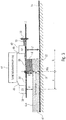
- Fig. 1 shows a well-known paver, such as in the EP 0 542 297 A1 is described.
- the paver is designated in its entirety by the reference numeral 10 and includes a tracked chassis 12 with which the paver 10 travels on the prepared ground 14.
- a height-adjustable screed 16 is arranged, which is articulated by means of a pulling arm 18 at a traction point 20 on the paver 10.
- a supply 22 of the asphalt material In front of the screed 16 there is a supply 22 of the asphalt material, this supply being constant by means of a known control of the speed of a screw-type conveying device 24 substantially over the entire width range of the screed 16 is held.
- the screed 16 floats on the asphalt of the road surface to be finished.
- the thickness of the road surface to be manufactured before its final consolidation by road rollers is adjusted by regulating the altitude of the trailing edge 26 of the screed 16. This height control is effected by changing the angle of attack of the screed 16, and is typically done by the control of actuating cylinders which engage the front ends of the tension arms 18.
- the paver comprises three ultrasonic sensors 28, 30, 32, which are fastened to a holder 34.
- the bracket 34 is attached to the pull arm 18.
- the three ultrasonic sensors 28, 30, 32 serve to scan a reference surface, which may be formed, for example, by an already manufactured or old web of the road surface.
- the layer thickness is desired, for example, to control the quality of the newly installed road surface. If the calculated layer thickness, for example a bituminous layer, is too low, then there is a risk that the road surface breaks up early, which results in costly repairs of the road surface. On the other hand, the layer thickness should be checked with regard to the amount of material used in order not to obstruct too much material, which would lead to increased costs.
- the object of the present invention is to provide an improved approach for determining the layer thickness of a built-in material by a paver material layer, which is less expensive, and which makes it possible to determine the layer thickness with increased accuracy.
- the paver according to the invention is advantageous because the layer thickness detection device is fixedly attached to the screed, so that a more accurate detection of the layer thickness is made possible, since the measuring device is mounted at the point at which the actual installation takes place.
- the origin of a coordinate system for detecting the layer thickness is just at the point where the actual installation of the material takes place.
- the approach according to the invention facilitates installation, since the layer thickness detection device only has to be fastened to the screed, in particular no attachment to another area of the paver is required, which makes the measuring system e.g. due to the movement of the paver negatively affected.
- the film thickness detection device includes a signal processing unit configured to calculate the layer thickness of the built-in material layer based on the sensor signals from the first sensor and the second sensor, the distances of the first sensor and the second sensor from the screed trailing edge, and the attachment heights of the first Sensor and the second sensor with respect to the screed trailing edge to capture.
- the inventive approach according to this embodiment is advantageous because only easily determinable variables are included in the calculation, namely the distance signals detected by the sensors and the well-defined distances of the sensors with respect to the screed trailing edge, so that in a simple manner with low signal processing effort exact determination of the layer thickness to the point where the installation of the layer takes place, namely with respect to the screed trailing edge, can be performed.
- the distances of the first sensor and the second sensor from the screed trailing edge and the attachment heights of the first sensor and the second sensor with respect to the screed trailing edge are the same, and the signal processing unit is configured to increase the layer thickness of the incorporated material layer based on the sensor signals from the screed first sensor and the second sensor, and to detect the mounting height of the first sensor and the second sensor with respect to the screed trailing edge.
- the inventive approach according to this embodiment is advantageous since, assuming the same distances of the sensors with respect to the screed trailing edge, the determination of the layer thickness can be greatly simplified, in a first, good approximation for small changes in angle only the mounting height of the sensors and the sensor signals to be included in the calculation.
- the inventive approach according to this embodiment is advantageous because it allows a simple calculation of the layer thickness, the sensors can be arranged depending on the circumstances with different distances from each other with respect to the screed trailing edge, the calculation is simplified because the sensors are installed with the same height with respect to the screed trailing edge.
- the inventive approach according to this embodiment is advantageous because a highly accurate determination of the layer thickness is made possible, wherein an optimization of the calculation algorithm is achieved in that the pivot point of the measuring device is exactly assumed at the screed trailing edge.
- the inventive approach according to this embodiment is advantageous because, due to the mounting of the sensors with a height with respect to the screed trailing edge, which is equal to the thickness of the screed, the determination of the mounting height is greatly simplified, for example, just the known thickness or height of the screed as Mounting height without further steps to determine the same would be required.
- the mounting heights of the first sensor and the second sensor with respect to the screed trailing edge are the same, and the signal processing unit is configured to perform a calibration for determining the mounting height, wherein the first sensor detects the distance to the ground during the calibration.
- the inventive approach according to this embodiment is advantageous because in a simple manner in a calibration process, the mounting heights of the first sensor and the second sensor, which are the same, can be determined by the first sensor in the calibration also the distance to the Underground recorded. According to the invention, a precise determination of the mounting height is thus made possible in a simple manner, which is also possible in the case of mounting the sensors at the level of the top of the screed, in order to determine the most accurate possible mounting height.
- the layer thickness detection device comprises at least one carrier attached to the screed, wherein the first sensor is disposed on the carrier at a first distance from the screed trailing edge, and wherein the second sensor is disposed on the carrier at a second distance from the screed trailing edge is.
- the inventive approach according to this embodiment is advantageous because using the carrier, the distance of the sensors with respect to the screed trailing edge can be adjusted easily, so that the first sensor safely scans the built-material layer and the second sensor safely scans the ground.
- the carrier comprises a measuring beam fixed to the screed, wherein the first sensor is disposed at a first end of the measuring beam at the first distance from the screed trailing edge, and wherein the second sensor is at a second end of the measuring beam at the second distance is arranged from the screed trailing edge.
- the measuring beam is rigid and immovably fixed to an upper side of the screed.
- a measuring beam according to this embodiment is advantageous, as this allows a simple attachment of the measuring arrangement to the screed, wherein in particular due to the fact that the measuring beam already comprises the respective sensors at its two ends, a simple attachment to the screed and in particular also a simple alignment of the sensors is ensured with respect to the screed.
- it may be provided to arrange a plurality of such measuring bars with corresponding sensors along the width of the screed. Due to the rigid design of the measuring beam and the movable attachment of the same at the top of the screed a simple and reliable measurement is ensured.
- the carrier comprises a first rigid support which is immovably fixed to the screed and to which the first sensor is arranged at the first distance from the screed trailing edge, and a second rigid support which is immovably fixed to the screed and to which the second Sensor is arranged at the second distance from the screed trailing edge.
- This exemplary embodiment is advantageous since, instead of a common measuring beam for fastening the two sensors, separate measuring beams or separate rigid supports can also be provided, depending on the circumstances, the first sensor and the second sensor at different positions with respect to the screed trailing edge and with respect to the screed trailing edge to arrange, for example, with different distances to the screed trailing edge and / or with different mounting heights.
- the first sensor and the second sensor include ultrasonic sensors, laser sensors, microwave sensors or a combination thereof.
- an approach which enables a continuous determination of the layer thickness on a road paver, which represents one of the most important tasks for determining quality parameters during asphalt paving.
- various measuring methods are known to determine the layer thickness in asphalt paving, but without achieving an accuracy that is within an acceptable range that can be usefully used for the application.
- an approach is taught in which the layer thickness measurement uses a measuring method which has an increased accuracy, which is achieved in particular by providing a measuring device which is permanently installed on the screed.
- Fig. 2 shows a paver according to an embodiment of the present invention.
- the in Fig. 2 shown road paver is the in Fig. 1
- the road paver shown in FIG. 1 similarly comprises the layer thickness detection device according to the invention.
- the in Fig. 2 paver shown does not include the in Fig. 1 shown ultrasonic sensors and the holder shown, instead, the layer thickness detection device according to the invention is attached to the screed 16.
- the in Fig. 1 shown sensors to control the installation of the material layer are maintained.
- the layer thickness detection device according to the invention comprises a carrier 36, which is fixed rigidly and immovably to the upper side of the screed 16, so that the carrier 36 moves with the screed 16.
- a first sensor 38 is arranged at a distance a from the screed trailing edge 26 in the direction of travel behind the screed 16.
- a second sensor 40 is arranged at a distance b from the screed trailing edge 26 in the direction of travel in front of the screed 16, also an ultrasonic sensor or a laser sensor which generates a distance signal s2.
- the first sensor 38 may be an ultrasonic sensor, a laser sensor or a microwave sensor, and generates a distance signal s1 indicative of the distance from the first sensor 38 to the surface 42a of the built-in layer 42.
- the second sensor 40 may be an ultrasonic sensor, a laser sensor or a microwave sensor, and generates a distance signal s 2, which indicates the distance from the second sensor 40 to the substrate 14.
- the layer thickness detection device further comprises a signal processing device 44, which in Fig. 2 is shown schematically, and may be part of a control of the paver 10, for example. Alternatively, the signal processing device may also be provided independently of other elements of the paver. In the embodiment shown, the signal processing device 44 may be configured as a microcontroller, which receives data from the sensors 38 and 40 via schematically illustrated connections 46, 48, which reflect the measured distance s1 or s2.
- the signal processing means determines 44, the thickness h B of the built-in layer 42.
- the signal processing means 44 may h B detect continuously or at fixed predetermined time intervals, output and / or store the layer thickness, wherein the signal processing means may comprise a memory and / or a display for this purpose, further, the in Fig. 2 are not shown in detail.
- the carrier 36 is shown schematically and is rigidly and immovably attached to a plank top edge 16b, so that the carrier 36 and thus the sensors 38 and 40 move together with the plank, so by means of the manner explained in more detail below of a calculation algorithm executed in the processing device 44, as mentioned above, the layer thickness h B of the built-in layer 42 can be determined.
- the mounting height of the sensors 38, 40 above the screed trailing edge 26 is a height equal to the thickness B and the height B of the screed 16, respectively.
- the approach according to the invention for coating thickness measurement for example when paving asphalt with the in Fig. 2 paver 10, based on the fact that the two height sensors 38, 40 are provided, which are arranged in a line along the direction of travel of the paver 10 and, according to one embodiment distance symmetrically to the screed trailing edge 26 so that the sensor 38, the distance s1 to the asphalt surface 42a the built-in asphalt layer 42 measures, and that the sensor 40 measures the distance s2 to the substrate 14.
- the two sensors 38, 40 are rigidly connected to the paver 16, by means of the carrier 36, in particular so that only slight twisting can occur.
- Fig. 3 shows a schematic representation of the screed geometry, such as in a road paver, as in Fig. 2 is shown, but can also be used in other road pavers.
- Fig. 3 shows the schematic structure for the layer thickness measurement using the distance sensors 38 and 40 and on the basis of the associated distance measured values s1 and s2.
- a symmetry point S is shown, which is located directly above the screed trailing edge 26, and that of the in Fig. 3 is traversed line L1 shown.
- the sensors 38, 40 are rigidly connected to the paver 16 via the carrier 36, in such a way that no twists are made in the direction of the imaginary line L1, in particular no twists in the vertical direction.
- the distance B which indicates the mounting height of the sensors with respect to the screed trailing edge 26, lies between the point of symmetry S and the surface 42 a of the installed asphalt layer 42.
- the distance B represents in the embodiment shown approximately a constant value, even if the screed 16 via the Switzerland Vietnamese slope is moved.
- the line L1 represents a reference line for the sensors 38 and 40, and at the same time the mounting height with respect to the point of symmetry S. In this connection, the line L1 may also be referred to as a mounting reference line.
- the distances a and b are the distances and installation distances of the sensors 38 and 40 relative to the screed trailing edge 26 and the symmetry point S.
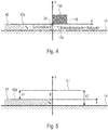
- the coordinate system for the coating thickness measurement using the sensors 38 and 40 is located directly on the screed trailing edge 26, as in Fig. 4 is clarified, which represents the position of the XY coordinate system with respect to the screed trailing edge 26. More specifically, the Y-origin of the coordinate system lies directly on the screed trailing edge 26, with the scrape edge defining the X origin.
- the coordinate system follows the movement of the screed trailing edge 26 during the paving process, where the X axis coincides negatively with the road surface 42a in its extension from zero.
- FIG Fig. 5 is an abstraction of the measured quantities for the coating thickness measurement.
- Fig. 5 is that on the basis of Fig. 4 illustrated coordinate system (XY coordinate system) shown, as well as the thickness h B of the built-in layer 42 and the distance measurements s1 and s2 of the sensors, which in Fig. 2 have been explained, the distances with respect to the asphalt surface 42a and with respect to the substrate 14, starting from the line L1, which is spaced from the zero point of the coordinate system by the installation height B of the sensors in the positive Y direction.
- the line L1 ' must again be aligned parallel to the ground 14, which is achieved by rotating the line L1' by the values ⁇ s1 and ⁇ s2 relative to the point of symmetry S, as shown by the arrows 50a and 50b in FIG Fig. 6 is shown. If one then corrects the value s2 ', which is the measured value which is detected by the sensor 40 at the changed bottom inclination, by ⁇ s2, then one obtains again the original measured value s2, ie the measured value which is for the imaginary and parallel to the background 14 (coordinate axis X) extending line L1 would result.
- the layer thickness is thus obtained according to the illustrated embodiment by adding the measured values obtained from the sensors and the subtraction of the double constant B, as stated above.
- a simple calculation rule is provided which enables a layer thickness determination with high accuracy with a simple mechanical design of the measuring device and with a simple calculation algorithm.
- the distances of the sensors 38, 40 from the screed trailing edge 26 are the same, but this is not absolutely necessary, and in particular depending on conditions that may be predetermined by the construction of the paver, also can not be possible.
- the constant B represents the mounting height of the sensors 38 and 40 with respect to the screed trailing edge 26, as described above with reference to FIGS Figures 3 and 5 has been explained, wherein in the preferred embodiments, the constant B is equal to the height of the screed.
- the attachment of the carrier may be at a distance from the top of the screed 16a, so that here the constant B indicates the thickness of the screed and the additional distance of the carrier over the screed.
- the mounting height of the sensors 38 and 40 with respect to the screed trailing edge 26 may be less than the screed thickness.
- This constant can be determined during a system calibration and remains stored as a constant parameter in the coating thickness measurement system.
- a measurement by means of the sensors 38 and 40, which now both refer to the substrate 14, since due to the missing layer 42, the layer thickness given in equation 12 to zero so that as part of the system calibration the constant B can be determined as follows: B s 2 + s 1 2
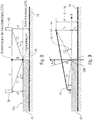
- Fig. 8 schematically shows the geometric characteristics that are used to determine the layer thickness with increased accuracy.
- Fig. 8 is the point of symmetry S, which was assumed in the simplified calculation at the top of the screed, namely, where the carrier is attached, now assumed at the screed trailing edge 26.
- the sensors 38, 40 perform a kind of pivoting movement which does not lead to a symmetrical change in position of the sensors 38, 40 with respect to the in Fig. 4 shown Bohlenkoordinatensystems leads.
- the coordinate system for calculating the layer thickness refers to the screed trailing edge and the newly laid asphalt layer 42
- the peak of the coordinate system is located at the screed trailing edge 26, and the X-axis lies in the surface 42a of the already laid asphalt layer.
- the coordinate system determined in this way is called the screed coordinate system, which is defined during installation.
- the screed 16 may change during installation even in their position in the coordinate system depending on the screed angle.
- the abovementioned embodiments of the layer thickness detection approach according to the invention are advantageous over conventional approaches, since the measurement setup according to the invention is mounted in a particularly simple manner on the screed 16 (see FIG Figures 2 and 3 ) is installed, and according to embodiments, for example, in an existing leveling system can be integrated.
- the distance of the sensors with respect to the screed trailing edge can be equal to the thickness of the screed according to a preferred embodiment, so that it requires no additional installation structures, but the measuring structure according to the invention can be easily attached to the existing screed. Equally advantageous may be to adjust a certain distance of the ultrasonic sensors from the surface to be detected in order to obtain an optimal measuring distance.
- the sensors are mounted as symmetrically as possible to the screed trailing edge, so that when using the calculation rule according to the first embodiment sufficiently accurate results, without the use of highly accurate calculation algorithm is required.
- the calculation algorithm according to the invention implements both the first algorithm and the second, more accurate algorithm, wherein, for example, depending on a detected adjustment of the screed, for example, when exceeding a critical angle, or if very accurate results are desired, the calculation of the layer thickness from the first algorithm to the second, more accurate algorithm.
- the layer thickness measuring device may be provided to use the data recorded by the layer thickness measuring device regarding the layer thickness for active control of the paver with respect to a position of the screed in order to maintain a predetermined layer thickness.
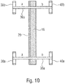
- Fig. 10 shows a schematic plan view of a possible installation of the layer thickness measuring system according to the present invention.
- the system includes two beams or measuring beams 36a, 36b secured to the screed 16, either on the screed top 16b or spaced upwardly from the screed top, with respective first sensors 38a, 38b and second sensors 40a, 40b the respective ends of the measuring beam 36a, 36b are arranged with the distances a, b to the screed trailing edge 26.
- only one measuring bar, but also more than two measuring bars with correspondingly arranged sensor systems can be provided, whereby the scanning area for the layer thickness measurement increases due to the plurality of sensors, so that a higher measured value accuracy is established.
- Fig. 11 shows an alternative embodiment of the measuring device according to the invention, in which the sensors 38 and 40 via separate, rigid support 36a, 36b are attached.
- the calculation algorithm has knowledge of the mounting heights of the sensors 38 and 40, which may also be different, as in FIG Fig. 11 Unlike in the embodiments described above, in which the sensors 38, 40 are arranged at opposite ends of a carrier or measuring beam, is in the in Fig. 11 shown embodiment, to arrange the sensor 38 higher than the sensor 40, via a rigid, attached to the plank top edge 16b support 36a, wherein the attachment 36a is such that the sensor 38 moves together with the screed 16, preferably so, that no connections occur.
- the sensor 40 is attached to the pull arm 18 that rotates the screed 16 via a second support structure 36b such that both the sensor 38 and the sensor 40 are disposed in a fixed, well-defined and non-changing relationship with the screed trailing edge 26 is, so that the above-described approaches for determining the layer thickness of the built-in layer 42 also in an embodiment according to Fig. 11 can be used, in which case then additionally the different heights of the sensors 38 and 40 must be considered.
- the above-described sensors may preferably be ultrasonic sensors, but laser scanners may also be used which then provide orthogonal vectors to the substrate or to the layer 42 for calculating the layer thickness.
- Other sensor configurations may include a combination of ultrasonic sensors and laser scanners, whereby only a simple laser distance measurement at both measuring positions is possible.
- aspects have been described in the context of a device, it will be understood that these aspects also constitute a description of the corresponding method such that a block or device of a device is also to be understood as a corresponding method step or feature of a method step is. Similarly, aspects described in connection with or as a method step also represent a description of a corresponding block or detail or feature of a corresponding device.
- embodiments of the invention may be implemented in hardware or in software.
- the implementation may be performed using a digital storage medium, such as a floppy disk, a DVD, a Blu-ray Disc, a CD, a ROM, a PROM, an EPROM, an EEPROM or FLASH memory, a hard disk, or other magnetic disk or optical memory are stored on the electronically readable control signals that can cooperate with a programmable computer system or cooperate such that the respective method is performed. Therefore, the digital storage medium can be computer readable.
- some embodiments according to the invention include a data carrier having electronically readable control signals capable of interacting with a programmable computer system such that one of the methods described herein is performed.
- embodiments of the present invention may be implemented as a computer program product having a program code, wherein the program code is operable to perform one of the methods when the computer program product runs on a computer.
- the program code can also be stored, for example, on a machine-readable carrier.
- inventions include the computer program for performing any of the methods described herein, wherein the computer program is stored on a machine-readable medium.
- an embodiment of the method according to the invention is thus a computer program which has a program code for performing one of the methods described herein when the computer program runs on a computer.
- a further embodiment of the inventive method is thus a data carrier (or a digital storage medium or a computer-readable medium) on which the computer program is recorded for carrying out one of the methods described herein.
- a further embodiment of the method according to the invention is thus a data stream or a sequence of signals, which represent the computer program for performing one of the methods described herein.
- the data stream or the sequence of signals may be configured, for example, to be transferred via a data communication connection, for example via the Internet.
- Another embodiment includes a processing device, such as a computer or a programmable logic device, that is configured or adapted to perform one of the methods described herein.
- a processing device such as a computer or a programmable logic device, that is configured or adapted to perform one of the methods described herein.
- Another embodiment includes a computer on which the computer program is installed to perform one of the methods described herein.
- a programmable logic device eg, a field programmable gate array, an FPGA
- a field programmable gate array may cooperate with a microprocessor to perform one of the methods described herein.
- the methods are performed by any hardware device. This may be a universal hardware such as a computer processor (CPU) or hardware specific to the process, such as an ASIC.
Landscapes
- Engineering & Computer Science (AREA)
- Architecture (AREA)
- Civil Engineering (AREA)
- Structural Engineering (AREA)
- Physics & Mathematics (AREA)
- General Physics & Mathematics (AREA)
- Mining & Mineral Resources (AREA)
- Road Paving Machines (AREA)
- Length Measuring Devices With Unspecified Measuring Means (AREA)
Priority Applications (3)
| Application Number | Priority Date | Filing Date | Title |
|---|---|---|---|
| EP18192758.3A EP3431925A1 (fr) | 2014-03-18 | 2014-03-18 | Finisseuse de route dotée d'un dispositif de détection de l'épaisseur de couche et procédé de détection de l'épaisseur d'une couche de matériau déposée |
| DK17156219.2T DK3228981T3 (en) | 2014-03-18 | 2014-03-18 | Road finishing machine with layer thickness sensing device and method for recording the thickness of an applied material layer |
| EP17156219.2A EP3228981B1 (fr) | 2014-03-18 | 2014-03-18 | Finisseuse de route dotée d'un dispositif de détection de l'épaisseur de couche et procédé de détection de l'épaisseur d'une couche de matériau installée |
Applications Claiming Priority (3)
| Application Number | Priority Date | Filing Date | Title |
|---|---|---|---|
| EP14160503.0A EP2921588B1 (fr) | 2014-03-18 | 2014-03-18 | Finisseuse de route dotée d'un dispositif de détection de l'épaisseur de couche et procédé de détection de l'épaisseur d'une couche de matériau déposée |
| EP17156219.2A EP3228981B1 (fr) | 2014-03-18 | 2014-03-18 | Finisseuse de route dotée d'un dispositif de détection de l'épaisseur de couche et procédé de détection de l'épaisseur d'une couche de matériau installée |
| EP15193387.6A EP3048199B2 (fr) | 2014-03-18 | 2014-03-18 | Finisseuse de route dotée d'un dispositif de détection de l'épaisseur de couche et procédé de détection de l'épaisseur d'une couche de matériau installée |
Related Parent Applications (3)
| Application Number | Title | Priority Date | Filing Date |
|---|---|---|---|
| EP14160503.0A Division EP2921588B1 (fr) | 2014-03-18 | 2014-03-18 | Finisseuse de route dotée d'un dispositif de détection de l'épaisseur de couche et procédé de détection de l'épaisseur d'une couche de matériau déposée |
| EP15193387.6A Division EP3048199B2 (fr) | 2014-03-18 | 2014-03-18 | Finisseuse de route dotée d'un dispositif de détection de l'épaisseur de couche et procédé de détection de l'épaisseur d'une couche de matériau installée |
| EP15193387.6A Division-Into EP3048199B2 (fr) | 2014-03-18 | 2014-03-18 | Finisseuse de route dotée d'un dispositif de détection de l'épaisseur de couche et procédé de détection de l'épaisseur d'une couche de matériau installée |
Related Child Applications (2)
| Application Number | Title | Priority Date | Filing Date |
|---|---|---|---|
| EP18192758.3A Division-Into EP3431925A1 (fr) | 2014-03-18 | 2014-03-18 | Finisseuse de route dotée d'un dispositif de détection de l'épaisseur de couche et procédé de détection de l'épaisseur d'une couche de matériau déposée |
| EP18192758.3A Division EP3431925A1 (fr) | 2014-03-18 | 2014-03-18 | Finisseuse de route dotée d'un dispositif de détection de l'épaisseur de couche et procédé de détection de l'épaisseur d'une couche de matériau déposée |
Publications (2)
| Publication Number | Publication Date |
|---|---|
| EP3228981A1 true EP3228981A1 (fr) | 2017-10-11 |
| EP3228981B1 EP3228981B1 (fr) | 2018-10-17 |
Family
ID=50289507
Family Applications (4)
| Application Number | Title | Priority Date | Filing Date |
|---|---|---|---|
| EP18192758.3A Withdrawn EP3431925A1 (fr) | 2014-03-18 | 2014-03-18 | Finisseuse de route dotée d'un dispositif de détection de l'épaisseur de couche et procédé de détection de l'épaisseur d'une couche de matériau déposée |
| EP17156219.2A Active EP3228981B1 (fr) | 2014-03-18 | 2014-03-18 | Finisseuse de route dotée d'un dispositif de détection de l'épaisseur de couche et procédé de détection de l'épaisseur d'une couche de matériau installée |
| EP15193387.6A Active EP3048199B2 (fr) | 2014-03-18 | 2014-03-18 | Finisseuse de route dotée d'un dispositif de détection de l'épaisseur de couche et procédé de détection de l'épaisseur d'une couche de matériau installée |
| EP14160503.0A Active EP2921588B1 (fr) | 2014-03-18 | 2014-03-18 | Finisseuse de route dotée d'un dispositif de détection de l'épaisseur de couche et procédé de détection de l'épaisseur d'une couche de matériau déposée |
Family Applications Before (1)
| Application Number | Title | Priority Date | Filing Date |
|---|---|---|---|
| EP18192758.3A Withdrawn EP3431925A1 (fr) | 2014-03-18 | 2014-03-18 | Finisseuse de route dotée d'un dispositif de détection de l'épaisseur de couche et procédé de détection de l'épaisseur d'une couche de matériau déposée |
Family Applications After (2)
| Application Number | Title | Priority Date | Filing Date |
|---|---|---|---|
| EP15193387.6A Active EP3048199B2 (fr) | 2014-03-18 | 2014-03-18 | Finisseuse de route dotée d'un dispositif de détection de l'épaisseur de couche et procédé de détection de l'épaisseur d'une couche de matériau installée |
| EP14160503.0A Active EP2921588B1 (fr) | 2014-03-18 | 2014-03-18 | Finisseuse de route dotée d'un dispositif de détection de l'épaisseur de couche et procédé de détection de l'épaisseur d'une couche de matériau déposée |
Country Status (6)
| Country | Link |
|---|---|
| US (3) | US9534349B2 (fr) |
| EP (4) | EP3431925A1 (fr) |
| JP (1) | JP6212656B2 (fr) |
| CN (1) | CN106460350B (fr) |
| DK (3) | DK2921588T5 (fr) |
| WO (1) | WO2015140166A1 (fr) |
Cited By (1)
| Publication number | Priority date | Publication date | Assignee | Title |
|---|---|---|---|---|
| EP4223932A1 (fr) | 2022-02-08 | 2023-08-09 | MOBA Mobile Automation AG | Système de mise à niveau pour machine de construction |
Families Citing this family (29)
| Publication number | Priority date | Publication date | Assignee | Title |
|---|---|---|---|---|
| EP3431925A1 (fr) * | 2014-03-18 | 2019-01-23 | MOBA Mobile Automation AG | Finisseuse de route dotée d'un dispositif de détection de l'épaisseur de couche et procédé de détection de l'épaisseur d'une couche de matériau déposée |
| EP3149245B1 (fr) * | 2014-05-28 | 2018-01-10 | Joseph Vögele AG | Ensemble poutre lisseuse avec poste de travail |
| US9618437B2 (en) * | 2015-04-29 | 2017-04-11 | Caterpillar Paving Products Inc. | System and method for monitoring wear of a screed plate |
| US9803324B2 (en) | 2016-01-26 | 2017-10-31 | Deere & Company | Ejector control for spreading material according to a profile |
| EP3208380B1 (fr) * | 2016-02-17 | 2021-08-11 | Joseph Vögele AG | Procede de commande d'une finisseuse de route sur roues et finisseuse de route sur roues |
| PL3214223T3 (pl) * | 2016-03-04 | 2019-11-29 | Voegele Ag J | Wykańczarka z boczną jednostką obsługową |
| US9932714B2 (en) | 2016-04-27 | 2018-04-03 | Caterpillar Paving Products Inc. | Systems, apparatuses and methods for material flow control for wide-width paving |
| DE102016207841B4 (de) | 2016-05-06 | 2018-01-04 | Moba Mobile Automation Aktiengesellschaft | Schichtdickenmessvorrichtung und Verfahren zur Schichtdickenmessung |
| GB2554872B (en) * | 2016-10-07 | 2019-12-04 | Kelly Anthony | A compaction compensation system |
| DE102016225502B4 (de) | 2016-12-19 | 2019-01-03 | Moba Mobile Automation Ag | Messsystem zur Schichtdickenerfassung |
| CN109667212B (zh) * | 2017-07-06 | 2021-04-16 | 河海大学 | 一种沥青路面摊铺压实厚度的测量方法 |
| CN107419643A (zh) * | 2017-08-31 | 2017-12-01 | 合肥益企学科技有限公司 | 一种沥青铺摊机的找平装置 |
| CN107858900B (zh) * | 2017-10-26 | 2019-12-24 | 雨发建设集团有限公司 | 一种沥青摊铺厚度实时检测装置及其检测方法 |
| CN111601929B (zh) * | 2018-01-03 | 2022-04-19 | 沃尔沃建筑设备公司 | 摊铺机和用于摊铺机整平板高度校准的方法 |
| EP3769038A1 (fr) | 2018-03-19 | 2021-01-27 | Ricoh Company, Ltd. | Appareil de traitement d'informations, appareil de capture d'images, système de traitement d'images et procédé de traitement d'informations |
| US10407844B1 (en) | 2018-04-23 | 2019-09-10 | Caterpillar Paving Products Inc. | Material feed system for a paving machine |
| US10407845B1 (en) * | 2018-08-22 | 2019-09-10 | Caterpillar Paving Products Inc. | Oscillation assembly for a paving machine |
| US11536827B2 (en) * | 2019-02-08 | 2022-12-27 | Geophysical Survey Systems, Inc. | Method for assessing the amount of rolling required to achieve optimal compaction of pre-rolled asphalt pavement |
| EP3739122B1 (fr) | 2019-05-14 | 2021-04-28 | Joseph Vögele AG | Finisseuse de route et procédé de détermination de l'épaisseur de couche de route |
| US10889942B2 (en) * | 2019-05-28 | 2021-01-12 | Caterpillar Paving Products Inc. | Method and system for positioning screed plates |
| US11674271B2 (en) | 2019-06-26 | 2023-06-13 | Caterpillar Paving Products Inc. | Control system for a paving machine |
| US11313086B2 (en) | 2019-12-16 | 2022-04-26 | Caterpillar Paving Products Inc. | Material density measurement for paver application |
| PL3851584T3 (pl) * | 2020-01-16 | 2023-03-20 | Joseph Vögele AG | Wykańczarka ze sterowaniem zagęszczenia |
| CN111811367B (zh) * | 2020-07-08 | 2022-01-11 | 广东筑成工程管理有限公司 | 一种监理用沥青路面厚度监测装置 |
| WO2022037764A1 (fr) | 2020-08-18 | 2022-02-24 | Moba Mobile Automation Ag | Système de mesure pour un engin de construction routière |
| EP4083322A1 (fr) | 2021-04-27 | 2022-11-02 | Leica Geosystems AG | Système et procédé de commande d'un processus de construction routière |
| CN113235548B (zh) * | 2021-05-13 | 2022-06-17 | 王运华 | 路基结构层厚度检测装置 |
| CN116145522B (zh) * | 2023-04-23 | 2023-07-18 | 中交二公局工程检测技术有限公司 | 一种沥青道路路面沥青层厚度检测装置 |
| CN117516327B (zh) * | 2024-01-08 | 2024-03-08 | 洛阳展尚建筑工程有限公司 | 一种公路铺设用厚度测量设备 |
Citations (7)
| Publication number | Priority date | Publication date | Assignee | Title |
|---|---|---|---|---|
| EP0542297A1 (fr) | 1991-11-15 | 1993-05-19 | MOBA-electronic Gesellschaft für Mobil-Automation mbH | Appareil de contrôle pour un finisseur |
| DE10025462A1 (de) * | 2000-05-23 | 2001-12-06 | Moba Mobile Automation Gmbh | Schichtdickenbestimmung unter Verwendung eines Neigungssensors |
| JP2002339314A (ja) * | 2001-05-14 | 2002-11-27 | Topcon Corp | アスファルトフィニッシャの舗装厚制御装置及びアスファルトフィニッシャ及び舗装施工システム |
| US7172363B2 (en) * | 2004-08-31 | 2007-02-06 | Caterpillar Paving Products Inc | Paving machine output monitoring system |
| EP2535456A1 (fr) | 2011-06-15 | 2012-12-19 | Joseph Vögele AG | Finisseuse de route dotée d'un dispositif de mesure de l'épaisseur de couche |
| EP2535457A1 (fr) | 2011-06-15 | 2012-12-19 | Joseph Vögele AG | Finisseuse de route dotée d'un dispositif de mesure de l'épaisseur de couche |
| EP2535458A1 (fr) | 2011-06-15 | 2012-12-19 | Joseph Vögele AG | Finisseuse de route dotée d'un dispositif de mesure de l'épaisseur de couche |
Family Cites Families (37)
| Publication number | Priority date | Publication date | Assignee | Title |
|---|---|---|---|---|
| DE2838123A1 (de) | 1978-09-01 | 1980-03-13 | Willi J Grimm | Vorrichtung zum einstellen und messen der einbaudicke und des einbauvolumens von strassenbelaegen |
| JP2584823B2 (ja) | 1988-04-22 | 1997-02-26 | 株式会社トキメック | 舗装厚測定装置 |
| JPH01278603A (ja) | 1988-04-27 | 1989-11-09 | Sumitomo Heavy Ind Ltd | 舗装厚検出装置 |
| JPH02136405A (ja) | 1988-11-15 | 1990-05-25 | Sumitomo Heavy Ind Ltd | 舗装厚検出装置 |
| JPH03225213A (ja) * | 1990-01-31 | 1991-10-04 | Sumitomo Constr Mach Co Ltd | 舗装厚検出装置 |
| JPH0749642B2 (ja) * | 1990-11-14 | 1995-05-31 | 株式会社新潟鐵工所 | 敷均し機械における舗装厚制御方法 |
| EP0510215B1 (fr) | 1990-11-14 | 1997-05-07 | Niigata Engineering Co., Ltd. | Dispositif pour régler l'épaisseur d'un revêtement de chaussée |
| JPH0743130Y2 (ja) * | 1990-11-19 | 1995-10-04 | 株式会社新潟鐵工所 | 敷きならし機械 |
| DE4040027A1 (de) | 1990-12-14 | 1992-06-17 | Voegele Ag J | Verfahren zum einstellen der staerke einer einbauschicht mit einem strassenfertiger |
| JPH0672406B2 (ja) * | 1991-04-19 | 1994-09-14 | 株式会社新潟鉄工所 | 舗装機械における合材の送出し量制御方法 |
| DE9114281U1 (fr) * | 1991-11-15 | 1992-01-09 | Moba-Electronic Gesellschaft Fuer Mobil-Automation Mbh, 6254 Elz, De | |
| US5356238A (en) * | 1993-03-10 | 1994-10-18 | Cedarapids, Inc. | Paver with material supply and mat grade and slope quality control apparatus and method |
| JP2612666B2 (ja) * | 1993-05-14 | 1997-05-21 | 日本無線株式会社 | アスファルトフィニッシャ |
| US5549412A (en) * | 1995-05-24 | 1996-08-27 | Blaw-Knox Construction Equipment Corporation | Position referencing, measuring and paving method and apparatus for a profiler and paver |
| US5752783A (en) | 1996-02-20 | 1998-05-19 | Blaw-Knox Construction Equipment Corporation | Paver with radar screed control |
| DE29619831U1 (de) | 1996-11-14 | 1997-01-09 | Moba Electronic Mobil Automat | Vorrichtung zum Steuern der Einbauhöhe eines Straßenfertigers |
| DE19647150C2 (de) * | 1996-11-14 | 2001-02-01 | Moba Mobile Automation Gmbh | Vorrichtung und Verfahren zum Steuern der Einbauhöhe eines Straßenfertigers |
| DE19709131C2 (de) | 1997-03-06 | 2003-02-20 | Abg Allg Baumaschinen Gmbh | Deckenfertiger |
| DE29721457U1 (de) | 1997-12-04 | 1998-01-29 | Voegele Ag J | Nivelliervorrichtung einer Einbaubohle eines Straßenfertigers |
| US5975473A (en) | 1998-03-12 | 1999-11-02 | Topcon Laser Systems, Inc. | Mounting device for non-contacting sensors |
| DE19836269C1 (de) | 1998-08-11 | 1999-08-26 | Abg Allg Baumaschinen Gmbh | Straßenfertiger |
| JP2000144626A (ja) * | 1998-11-12 | 2000-05-26 | Tokimec Inc | 舗装厚さ制御装置 |
| DE10025474B4 (de) | 2000-05-23 | 2011-03-10 | Moba - Mobile Automation Gmbh | Schichtdickenbestimmung durch relative Lageerfassung zwischen Traktor und Zugarm eines Straßenfertigers |
| US6406970B1 (en) | 2001-08-31 | 2002-06-18 | Infineon Technologies North America Corp. | Buried strap formation without TTO deposition |
| DE10234217B4 (de) | 2002-07-27 | 2009-02-05 | Hermann Kirchner Gmbh & Co Kg | Verfahren und Vorrichtung zur Ermittlung der Dicke einer Asphaltschicht |
| DE102005022266A1 (de) | 2005-05-10 | 2006-11-16 | Abg Allgemeine Baumaschinen-Gesellschaft Mbh | Fertiger zum bodenseitigen Einbau von Schichten für Straßen oder dgl. |
| EP2025811B1 (fr) | 2007-08-16 | 2019-04-24 | Joseph Vögele AG | Procédé pour l'application d'une couche de revêtement et finisseuse pour exécuter ce procédé |
| US8070385B2 (en) * | 2008-07-21 | 2011-12-06 | Caterpillar Trimble Control Technologies, Llc | Paving machine control and method |
| US20100129152A1 (en) * | 2008-11-25 | 2010-05-27 | Trimble Navigation Limited | Method of covering an area with a layer of compressible material |
| US8371769B2 (en) * | 2010-04-14 | 2013-02-12 | Caterpillar Trimble Control Technologies Llc | Paving machine control and method |
| EP2514871B1 (fr) * | 2011-04-18 | 2016-05-11 | Joseph Vögele AG | Procédé pour la pose et le compactage d'une couche d'asphalte |
| US9004811B2 (en) * | 2012-02-24 | 2015-04-14 | Caterpillar Paving Products Inc. | Systems and methods for aiming asphalt material feed sensors |
| US8979423B2 (en) * | 2012-10-10 | 2015-03-17 | Caterpillar Paving Products Inc. | Automatic material height sensor for asphalt pavers |
| US8944719B2 (en) * | 2012-11-09 | 2015-02-03 | Caterpillar Paving Products Inc. | Tracking of machine system movements in paving machine |
| EP3431925A1 (fr) * | 2014-03-18 | 2019-01-23 | MOBA Mobile Automation AG | Finisseuse de route dotée d'un dispositif de détection de l'épaisseur de couche et procédé de détection de l'épaisseur d'une couche de matériau déposée |
| US9382675B2 (en) * | 2014-06-16 | 2016-07-05 | Caterpillar Paving Products Inc. | Electric powered systems for paving machines |
| DE102014018113A1 (de) | 2014-10-10 | 2016-04-14 | Dynapac Gmbh | Straßenfertiger und Verfahren zur Herstellung eines Straßenbelags |
-
2014
- 2014-03-18 EP EP18192758.3A patent/EP3431925A1/fr not_active Withdrawn
- 2014-03-18 DK DK14160503.0T patent/DK2921588T5/en active
- 2014-03-18 DK DK15193387.6T patent/DK3048199T4/da active
- 2014-03-18 EP EP17156219.2A patent/EP3228981B1/fr active Active
- 2014-03-18 DK DK17156219.2T patent/DK3228981T3/en active
- 2014-03-18 EP EP15193387.6A patent/EP3048199B2/fr active Active
- 2014-03-18 EP EP14160503.0A patent/EP2921588B1/fr active Active
-
2015
- 2015-01-30 US US14/609,481 patent/US9534349B2/en active Active
- 2015-03-17 CN CN201580014565.8A patent/CN106460350B/zh active Active
- 2015-03-17 WO PCT/EP2015/055555 patent/WO2015140166A1/fr active Application Filing
- 2015-03-17 JP JP2016557929A patent/JP6212656B2/ja active Active
-
2016
- 2016-09-14 US US15/264,640 patent/US9988773B2/en active Active
-
2018
- 2018-04-27 US US15/964,143 patent/US10227738B2/en active Active
Patent Citations (7)
| Publication number | Priority date | Publication date | Assignee | Title |
|---|---|---|---|---|
| EP0542297A1 (fr) | 1991-11-15 | 1993-05-19 | MOBA-electronic Gesellschaft für Mobil-Automation mbH | Appareil de contrôle pour un finisseur |
| DE10025462A1 (de) * | 2000-05-23 | 2001-12-06 | Moba Mobile Automation Gmbh | Schichtdickenbestimmung unter Verwendung eines Neigungssensors |
| JP2002339314A (ja) * | 2001-05-14 | 2002-11-27 | Topcon Corp | アスファルトフィニッシャの舗装厚制御装置及びアスファルトフィニッシャ及び舗装施工システム |
| US7172363B2 (en) * | 2004-08-31 | 2007-02-06 | Caterpillar Paving Products Inc | Paving machine output monitoring system |
| EP2535456A1 (fr) | 2011-06-15 | 2012-12-19 | Joseph Vögele AG | Finisseuse de route dotée d'un dispositif de mesure de l'épaisseur de couche |
| EP2535457A1 (fr) | 2011-06-15 | 2012-12-19 | Joseph Vögele AG | Finisseuse de route dotée d'un dispositif de mesure de l'épaisseur de couche |
| EP2535458A1 (fr) | 2011-06-15 | 2012-12-19 | Joseph Vögele AG | Finisseuse de route dotée d'un dispositif de mesure de l'épaisseur de couche |
Cited By (2)
| Publication number | Priority date | Publication date | Assignee | Title |
|---|---|---|---|---|
| EP4223932A1 (fr) | 2022-02-08 | 2023-08-09 | MOBA Mobile Automation AG | Système de mise à niveau pour machine de construction |
| DE102022201294A1 (de) | 2022-02-08 | 2023-08-10 | Moba Mobile Automation Aktiengesellschaft | Nivelliersystem für eine Baumaschine |
Also Published As
| Publication number | Publication date |
|---|---|
| US20150267361A1 (en) | 2015-09-24 |
| DK3228981T3 (en) | 2019-01-21 |
| DK2921588T5 (en) | 2017-06-19 |
| CN106460350A (zh) | 2017-02-22 |
| EP3228981B1 (fr) | 2018-10-17 |
| EP2921588A1 (fr) | 2015-09-23 |
| DK3048199T3 (en) | 2017-06-19 |
| EP3048199B1 (fr) | 2017-03-29 |
| DK2921588T3 (en) | 2017-03-13 |
| EP3431925A1 (fr) | 2019-01-23 |
| EP3048199B2 (fr) | 2020-01-22 |
| JP6212656B2 (ja) | 2017-10-11 |
| EP3048199A1 (fr) | 2016-07-27 |
| EP2921588B1 (fr) | 2016-12-14 |
| US20170002525A1 (en) | 2017-01-05 |
| WO2015140166A1 (fr) | 2015-09-24 |
| CN106460350B (zh) | 2019-10-15 |
| US10227738B2 (en) | 2019-03-12 |
| DK3048199T4 (da) | 2020-04-27 |
| JP2017508088A (ja) | 2017-03-23 |
| US9534349B2 (en) | 2017-01-03 |
| US20180245295A1 (en) | 2018-08-30 |
| US9988773B2 (en) | 2018-06-05 |
Similar Documents
| Publication | Publication Date | Title |
|---|---|---|
| EP3228981B1 (fr) | Finisseuse de route dotée d'un dispositif de détection de l'épaisseur de couche et procédé de détection de l'épaisseur d'une couche de matériau installée | |
| DE102011001542B4 (de) | Steuerung und entsprechendes Verfahren für eine Teermaschine | |
| EP0542297B1 (fr) | Appareil de contrôle pour un finisseur | |
| EP2738309B1 (fr) | Engin de construction routière et procédé de mesure de la profondeur de la fraise | |
| EP2535456B1 (fr) | Finisseuse de route dotée d'un dispositif de mesure de l'épaisseur de couche | |
| EP2927372B1 (fr) | Engin automobile et procédé de commande d'un engin automobile | |
| EP3739122B1 (fr) | Finisseuse de route et procédé de détermination de l'épaisseur de couche de route | |
| EP2535457B1 (fr) | Finisseuse de route dotée d'un dispositif de mesure de l'épaisseur de couche | |
| DE102016207584B3 (de) | Vorrichtung und verfahren zur bestimmung der temperatur eines durch eine baumaschine aufgebrachten strassenbaumaterials sowie eine baumaschine mit einer derartigen vorrichtung | |
| EP2025811B1 (fr) | Procédé pour l'application d'une couche de revêtement et finisseuse pour exécuter ce procédé | |
| DE102014222693B4 (de) | Vorrichtung zur bestimmung der temperatur eines durch eine baumaschine aufgebrachten strassenbaumaterials sowie eine baumaschine mit einer derartigen vorrichtung | |
| EP3498914B1 (fr) | Ajustement de réglage de cylindre à niveler dans une finisseuse de route | |
| EP3647494B1 (fr) | Raboteuse et procédé de commande d'une raboteuse | |
| EP3130939A1 (fr) | Finisseuse de route dotée d'un dispositif d'égalisation par radar et procédé de commande | |
| DE102016225502B4 (de) | Messsystem zur Schichtdickenerfassung | |
| DE102016207841B4 (de) | Schichtdickenmessvorrichtung und Verfahren zur Schichtdickenmessung | |
| DE10025474B4 (de) | Schichtdickenbestimmung durch relative Lageerfassung zwischen Traktor und Zugarm eines Straßenfertigers | |
| EP3670747B1 (fr) | Engin de construction autonome et procédé d'usinage d'un revêtement de sol | |
| DE102016207181B4 (de) | Verfahren und System zum Bestimmen einer Position eines Fahrzeugs auf einer Fahrbahn | |
| DE10025462A1 (de) | Schichtdickenbestimmung unter Verwendung eines Neigungssensors | |
| EP3708711B1 (fr) | Système de capteurs avec unité de calcul pour finisseuse de route permettant de calculer une consommation de matière | |
| WO2022037764A1 (fr) | Système de mesure pour un engin de construction routière | |
| DE202018006746U1 (de) | Sensorsystem für einen Straßenfertiger | |
| EP4223932A1 (fr) | Système de mise à niveau pour machine de construction | |
| EP3841380A1 (fr) | Système de mesure de compactage |
Legal Events
| Date | Code | Title | Description |
|---|---|---|---|
| PUAI | Public reference made under article 153(3) epc to a published international application that has entered the european phase |
Free format text: ORIGINAL CODE: 0009012 |
|
| STAA | Information on the status of an ep patent application or granted ep patent |
Free format text: STATUS: THE APPLICATION HAS BEEN PUBLISHED |
|
| AC | Divisional application: reference to earlier application |
Ref document number: 2921588 Country of ref document: EP Kind code of ref document: P Ref document number: 3048199 Country of ref document: EP Kind code of ref document: P |
|
| AK | Designated contracting states |
Kind code of ref document: A1 Designated state(s): AL AT BE BG CH CY CZ DE DK EE ES FI FR GB GR HR HU IE IS IT LI LT LU LV MC MK MT NL NO PL PT RO RS SE SI SK SM TR |
|
| STAA | Information on the status of an ep patent application or granted ep patent |
Free format text: STATUS: REQUEST FOR EXAMINATION WAS MADE |
|
| 17P | Request for examination filed |
Effective date: 20180117 |
|
| RBV | Designated contracting states (corrected) |
Designated state(s): AL AT BE BG CH CY CZ DE DK EE ES FI FR GB GR HR HU IE IS IT LI LT LU LV MC MK MT NL NO PL PT RO RS SE SI SK SM TR |
|
| GRAP | Despatch of communication of intention to grant a patent |
Free format text: ORIGINAL CODE: EPIDOSNIGR1 |
|
| STAA | Information on the status of an ep patent application or granted ep patent |
Free format text: STATUS: GRANT OF PATENT IS INTENDED |
|
| INTG | Intention to grant announced |
Effective date: 20180423 |
|
| GRAS | Grant fee paid |
Free format text: ORIGINAL CODE: EPIDOSNIGR3 |
|
| GRAA | (expected) grant |
Free format text: ORIGINAL CODE: 0009210 |
|
| STAA | Information on the status of an ep patent application or granted ep patent |
Free format text: STATUS: THE PATENT HAS BEEN GRANTED |
|
| AC | Divisional application: reference to earlier application |
Ref document number: 3048199 Country of ref document: EP Kind code of ref document: P Ref document number: 2921588 Country of ref document: EP Kind code of ref document: P |
|
| AK | Designated contracting states |
Kind code of ref document: B1 Designated state(s): AL AT BE BG CH CY CZ DE DK EE ES FI FR GB GR HR HU IE IS IT LI LT LU LV MC MK MT NL NO PL PT RO RS SE SI SK SM TR |
|
| REG | Reference to a national code |
Ref country code: GB Ref legal event code: FG4D Free format text: NOT ENGLISH |
|
| REG | Reference to a national code |
Ref country code: CH Ref legal event code: EP |
|
| REG | Reference to a national code |
Ref country code: IE Ref legal event code: FG4D Free format text: LANGUAGE OF EP DOCUMENT: GERMAN |
|
| REG | Reference to a national code |
Ref country code: DE Ref legal event code: R096 Ref document number: 502014009830 Country of ref document: DE Ref country code: AT Ref legal event code: REF Ref document number: 1054596 Country of ref document: AT Kind code of ref document: T Effective date: 20181115 |
|
| REG | Reference to a national code |
Ref country code: DK Ref legal event code: T3 Effective date: 20190109 |
|
| REG | Reference to a national code |
Ref country code: NL Ref legal event code: MP Effective date: 20181017 |
|
| REG | Reference to a national code |
Ref country code: LT Ref legal event code: MG4D |
|
| PG25 | Lapsed in a contracting state [announced via postgrant information from national office to epo] |
Ref country code: NL Free format text: LAPSE BECAUSE OF FAILURE TO SUBMIT A TRANSLATION OF THE DESCRIPTION OR TO PAY THE FEE WITHIN THE PRESCRIBED TIME-LIMIT Effective date: 20181017 |
|
| PG25 | Lapsed in a contracting state [announced via postgrant information from national office to epo] |
Ref country code: FI Free format text: LAPSE BECAUSE OF FAILURE TO SUBMIT A TRANSLATION OF THE DESCRIPTION OR TO PAY THE FEE WITHIN THE PRESCRIBED TIME-LIMIT Effective date: 20181017 Ref country code: LT Free format text: LAPSE BECAUSE OF FAILURE TO SUBMIT A TRANSLATION OF THE DESCRIPTION OR TO PAY THE FEE WITHIN THE PRESCRIBED TIME-LIMIT Effective date: 20181017 Ref country code: PL Free format text: LAPSE BECAUSE OF FAILURE TO SUBMIT A TRANSLATION OF THE DESCRIPTION OR TO PAY THE FEE WITHIN THE PRESCRIBED TIME-LIMIT Effective date: 20181017 Ref country code: BG Free format text: LAPSE BECAUSE OF FAILURE TO SUBMIT A TRANSLATION OF THE DESCRIPTION OR TO PAY THE FEE WITHIN THE PRESCRIBED TIME-LIMIT Effective date: 20190117 Ref country code: HR Free format text: LAPSE BECAUSE OF FAILURE TO SUBMIT A TRANSLATION OF THE DESCRIPTION OR TO PAY THE FEE WITHIN THE PRESCRIBED TIME-LIMIT Effective date: 20181017 Ref country code: LV Free format text: LAPSE BECAUSE OF FAILURE TO SUBMIT A TRANSLATION OF THE DESCRIPTION OR TO PAY THE FEE WITHIN THE PRESCRIBED TIME-LIMIT Effective date: 20181017 Ref country code: ES Free format text: LAPSE BECAUSE OF FAILURE TO SUBMIT A TRANSLATION OF THE DESCRIPTION OR TO PAY THE FEE WITHIN THE PRESCRIBED TIME-LIMIT Effective date: 20181017 Ref country code: NO Free format text: LAPSE BECAUSE OF FAILURE TO SUBMIT A TRANSLATION OF THE DESCRIPTION OR TO PAY THE FEE WITHIN THE PRESCRIBED TIME-LIMIT Effective date: 20190117 Ref country code: IS Free format text: LAPSE BECAUSE OF FAILURE TO SUBMIT A TRANSLATION OF THE DESCRIPTION OR TO PAY THE FEE WITHIN THE PRESCRIBED TIME-LIMIT Effective date: 20190217 |
|
| PG25 | Lapsed in a contracting state [announced via postgrant information from national office to epo] |
Ref country code: GR Free format text: LAPSE BECAUSE OF FAILURE TO SUBMIT A TRANSLATION OF THE DESCRIPTION OR TO PAY THE FEE WITHIN THE PRESCRIBED TIME-LIMIT Effective date: 20190118 Ref country code: PT Free format text: LAPSE BECAUSE OF FAILURE TO SUBMIT A TRANSLATION OF THE DESCRIPTION OR TO PAY THE FEE WITHIN THE PRESCRIBED TIME-LIMIT Effective date: 20190217 Ref country code: RS Free format text: LAPSE BECAUSE OF FAILURE TO SUBMIT A TRANSLATION OF THE DESCRIPTION OR TO PAY THE FEE WITHIN THE PRESCRIBED TIME-LIMIT Effective date: 20181017 Ref country code: AL Free format text: LAPSE BECAUSE OF FAILURE TO SUBMIT A TRANSLATION OF THE DESCRIPTION OR TO PAY THE FEE WITHIN THE PRESCRIBED TIME-LIMIT Effective date: 20181017 Ref country code: SE Free format text: LAPSE BECAUSE OF FAILURE TO SUBMIT A TRANSLATION OF THE DESCRIPTION OR TO PAY THE FEE WITHIN THE PRESCRIBED TIME-LIMIT Effective date: 20181017 |
|
| REG | Reference to a national code |
Ref country code: DE Ref legal event code: R097 Ref document number: 502014009830 Country of ref document: DE |
|
| PG25 | Lapsed in a contracting state [announced via postgrant information from national office to epo] |
Ref country code: IT Free format text: LAPSE BECAUSE OF FAILURE TO SUBMIT A TRANSLATION OF THE DESCRIPTION OR TO PAY THE FEE WITHIN THE PRESCRIBED TIME-LIMIT Effective date: 20181017 Ref country code: CZ Free format text: LAPSE BECAUSE OF FAILURE TO SUBMIT A TRANSLATION OF THE DESCRIPTION OR TO PAY THE FEE WITHIN THE PRESCRIBED TIME-LIMIT Effective date: 20181017 |
|
| PLBE | No opposition filed within time limit |
Free format text: ORIGINAL CODE: 0009261 |
|
| STAA | Information on the status of an ep patent application or granted ep patent |
Free format text: STATUS: NO OPPOSITION FILED WITHIN TIME LIMIT |
|
| PG25 | Lapsed in a contracting state [announced via postgrant information from national office to epo] |
Ref country code: SK Free format text: LAPSE BECAUSE OF FAILURE TO SUBMIT A TRANSLATION OF THE DESCRIPTION OR TO PAY THE FEE WITHIN THE PRESCRIBED TIME-LIMIT Effective date: 20181017 Ref country code: SM Free format text: LAPSE BECAUSE OF FAILURE TO SUBMIT A TRANSLATION OF THE DESCRIPTION OR TO PAY THE FEE WITHIN THE PRESCRIBED TIME-LIMIT Effective date: 20181017 Ref country code: EE Free format text: LAPSE BECAUSE OF FAILURE TO SUBMIT A TRANSLATION OF THE DESCRIPTION OR TO PAY THE FEE WITHIN THE PRESCRIBED TIME-LIMIT Effective date: 20181017 Ref country code: RO Free format text: LAPSE BECAUSE OF FAILURE TO SUBMIT A TRANSLATION OF THE DESCRIPTION OR TO PAY THE FEE WITHIN THE PRESCRIBED TIME-LIMIT Effective date: 20181017 |
|
| 26N | No opposition filed |
Effective date: 20190718 |
|
| PG25 | Lapsed in a contracting state [announced via postgrant information from national office to epo] |
Ref country code: MC Free format text: LAPSE BECAUSE OF FAILURE TO SUBMIT A TRANSLATION OF THE DESCRIPTION OR TO PAY THE FEE WITHIN THE PRESCRIBED TIME-LIMIT Effective date: 20181017 Ref country code: SI Free format text: LAPSE BECAUSE OF FAILURE TO SUBMIT A TRANSLATION OF THE DESCRIPTION OR TO PAY THE FEE WITHIN THE PRESCRIBED TIME-LIMIT Effective date: 20181017 |
|
| REG | Reference to a national code |
Ref country code: CH Ref legal event code: PL |
|
| PG25 | Lapsed in a contracting state [announced via postgrant information from national office to epo] |
Ref country code: LU Free format text: LAPSE BECAUSE OF NON-PAYMENT OF DUE FEES Effective date: 20190318 |
|
| REG | Reference to a national code |
Ref country code: BE Ref legal event code: MM Effective date: 20190331 |
|
| PG25 | Lapsed in a contracting state [announced via postgrant information from national office to epo] |
Ref country code: IE Free format text: LAPSE BECAUSE OF NON-PAYMENT OF DUE FEES Effective date: 20190318 Ref country code: LI Free format text: LAPSE BECAUSE OF NON-PAYMENT OF DUE FEES Effective date: 20190331 Ref country code: CH Free format text: LAPSE BECAUSE OF NON-PAYMENT OF DUE FEES Effective date: 20190331 |
|
| PG25 | Lapsed in a contracting state [announced via postgrant information from national office to epo] |
Ref country code: BE Free format text: LAPSE BECAUSE OF NON-PAYMENT OF DUE FEES Effective date: 20190331 |
|
| PG25 | Lapsed in a contracting state [announced via postgrant information from national office to epo] |
Ref country code: TR Free format text: LAPSE BECAUSE OF FAILURE TO SUBMIT A TRANSLATION OF THE DESCRIPTION OR TO PAY THE FEE WITHIN THE PRESCRIBED TIME-LIMIT Effective date: 20181017 |
|
| PG25 | Lapsed in a contracting state [announced via postgrant information from national office to epo] |
Ref country code: MT Free format text: LAPSE BECAUSE OF FAILURE TO SUBMIT A TRANSLATION OF THE DESCRIPTION OR TO PAY THE FEE WITHIN THE PRESCRIBED TIME-LIMIT Effective date: 20181017 |
|
| REG | Reference to a national code |
Ref country code: AT Ref legal event code: MM01 Ref document number: 1054596 Country of ref document: AT Kind code of ref document: T Effective date: 20190318 |
|
| PG25 | Lapsed in a contracting state [announced via postgrant information from national office to epo] |
Ref country code: AT Free format text: LAPSE BECAUSE OF NON-PAYMENT OF DUE FEES Effective date: 20190318 |
|
| PG25 | Lapsed in a contracting state [announced via postgrant information from national office to epo] |
Ref country code: CY Free format text: LAPSE BECAUSE OF FAILURE TO SUBMIT A TRANSLATION OF THE DESCRIPTION OR TO PAY THE FEE WITHIN THE PRESCRIBED TIME-LIMIT Effective date: 20181017 |
|
| PG25 | Lapsed in a contracting state [announced via postgrant information from national office to epo] |
Ref country code: HU Free format text: LAPSE BECAUSE OF FAILURE TO SUBMIT A TRANSLATION OF THE DESCRIPTION OR TO PAY THE FEE WITHIN THE PRESCRIBED TIME-LIMIT; INVALID AB INITIO Effective date: 20140318 |
|
| PG25 | Lapsed in a contracting state [announced via postgrant information from national office to epo] |
Ref country code: MK Free format text: LAPSE BECAUSE OF FAILURE TO SUBMIT A TRANSLATION OF THE DESCRIPTION OR TO PAY THE FEE WITHIN THE PRESCRIBED TIME-LIMIT Effective date: 20181017 |
|
| PGFP | Annual fee paid to national office [announced via postgrant information from national office to epo] |
Ref country code: FR Payment date: 20230322 Year of fee payment: 10 Ref country code: DK Payment date: 20230321 Year of fee payment: 10 |
|
| PGFP | Annual fee paid to national office [announced via postgrant information from national office to epo] |
Ref country code: GB Payment date: 20230322 Year of fee payment: 10 Ref country code: DE Payment date: 20230208 Year of fee payment: 10 |
|
| P01 | Opt-out of the competence of the unified patent court (upc) registered |
Effective date: 20230523 |
|
| PGFP | Annual fee paid to national office [announced via postgrant information from national office to epo] |
Ref country code: DE Payment date: 20240220 Year of fee payment: 11 Ref country code: GB Payment date: 20240320 Year of fee payment: 11 |