EP3224088B1 - Self-fastened bracket for mounting a wire harness to a support structure of a vehicle and vehicle comprising the same - Google Patents
Self-fastened bracket for mounting a wire harness to a support structure of a vehicle and vehicle comprising the same Download PDFInfo
- Publication number
- EP3224088B1 EP3224088B1 EP14815227.5A EP14815227A EP3224088B1 EP 3224088 B1 EP3224088 B1 EP 3224088B1 EP 14815227 A EP14815227 A EP 14815227A EP 3224088 B1 EP3224088 B1 EP 3224088B1
- Authority
- EP
- European Patent Office
- Prior art keywords
- fixation means
- rigid portion
- vehicle
- tie
- flexible arm
- Prior art date
- Legal status (The legal status is an assumption and is not a legal conclusion. Google has not performed a legal analysis and makes no representation as to the accuracy of the status listed.)
- Active
Links
- 238000000034 method Methods 0.000 claims description 17
- 239000000463 material Substances 0.000 claims description 11
- 229920003023 plastic Polymers 0.000 description 5
- 239000004033 plastic Substances 0.000 description 5
- 230000007797 corrosion Effects 0.000 description 4
- 238000005260 corrosion Methods 0.000 description 4
- 229920002401 polyacrylamide Polymers 0.000 description 4
- 239000012530 fluid Substances 0.000 description 3
- 230000003247 decreasing effect Effects 0.000 description 2
- 230000005489 elastic deformation Effects 0.000 description 2
- 229920001971 elastomer Polymers 0.000 description 2
- 238000009429 electrical wiring Methods 0.000 description 2
- 239000000446 fuel Substances 0.000 description 2
- 229920000642 polymer Polymers 0.000 description 2
- 230000005540 biological transmission Effects 0.000 description 1
- 238000004891 communication Methods 0.000 description 1
- 238000010276 construction Methods 0.000 description 1
- 230000001627 detrimental effect Effects 0.000 description 1
- 238000006073 displacement reaction Methods 0.000 description 1
- 239000000806 elastomer Substances 0.000 description 1
- 239000003292 glue Substances 0.000 description 1
- 229920000140 heteropolymer Polymers 0.000 description 1
- 229920001519 homopolymer Polymers 0.000 description 1
- 229910052751 metal Inorganic materials 0.000 description 1
- 229910001092 metal group alloy Inorganic materials 0.000 description 1
- 238000012986 modification Methods 0.000 description 1
- 230000004048 modification Effects 0.000 description 1
- 239000003973 paint Substances 0.000 description 1
- 229920005989 resin Polymers 0.000 description 1
- 239000011347 resin Substances 0.000 description 1
- 238000010079 rubber tapping Methods 0.000 description 1
- 229920002994 synthetic fiber Polymers 0.000 description 1
- 229920001169 thermoplastic Polymers 0.000 description 1
- 239000012815 thermoplastic material Substances 0.000 description 1
- 239000004416 thermosoftening plastic Substances 0.000 description 1
Images


Classifications
-
- B—PERFORMING OPERATIONS; TRANSPORTING
- B60—VEHICLES IN GENERAL
- B60R—VEHICLES, VEHICLE FITTINGS, OR VEHICLE PARTS, NOT OTHERWISE PROVIDED FOR
- B60R16/00—Electric or fluid circuits specially adapted for vehicles and not otherwise provided for; Arrangement of elements of electric or fluid circuits specially adapted for vehicles and not otherwise provided for
- B60R16/02—Electric or fluid circuits specially adapted for vehicles and not otherwise provided for; Arrangement of elements of electric or fluid circuits specially adapted for vehicles and not otherwise provided for electric constitutive elements
- B60R16/0207—Wire harnesses
- B60R16/0215—Protecting, fastening and routing means therefor
-
- F—MECHANICAL ENGINEERING; LIGHTING; HEATING; WEAPONS; BLASTING
- F16—ENGINEERING ELEMENTS AND UNITS; GENERAL MEASURES FOR PRODUCING AND MAINTAINING EFFECTIVE FUNCTIONING OF MACHINES OR INSTALLATIONS; THERMAL INSULATION IN GENERAL
- F16B—DEVICES FOR FASTENING OR SECURING CONSTRUCTIONAL ELEMENTS OR MACHINE PARTS TOGETHER, e.g. NAILS, BOLTS, CIRCLIPS, CLAMPS, CLIPS OR WEDGES; JOINTS OR JOINTING
- F16B2/00—Friction-grip releasable fastenings
- F16B2/02—Clamps, i.e. with gripping action effected by positive means other than the inherent resistance to deformation of the material of the fastening
- F16B2/06—Clamps, i.e. with gripping action effected by positive means other than the inherent resistance to deformation of the material of the fastening external, i.e. with contracting action
- F16B2/08—Clamps, i.e. with gripping action effected by positive means other than the inherent resistance to deformation of the material of the fastening external, i.e. with contracting action using bands
-
- F—MECHANICAL ENGINEERING; LIGHTING; HEATING; WEAPONS; BLASTING
- F16—ENGINEERING ELEMENTS AND UNITS; GENERAL MEASURES FOR PRODUCING AND MAINTAINING EFFECTIVE FUNCTIONING OF MACHINES OR INSTALLATIONS; THERMAL INSULATION IN GENERAL
- F16L—PIPES; JOINTS OR FITTINGS FOR PIPES; SUPPORTS FOR PIPES, CABLES OR PROTECTIVE TUBING; MEANS FOR THERMAL INSULATION IN GENERAL
- F16L3/00—Supports for pipes, cables or protective tubing, e.g. hangers, holders, clamps, cleats, clips, brackets
- F16L3/08—Supports for pipes, cables or protective tubing, e.g. hangers, holders, clamps, cleats, clips, brackets substantially surrounding the pipe, cable or protective tubing
- F16L3/10—Supports for pipes, cables or protective tubing, e.g. hangers, holders, clamps, cleats, clips, brackets substantially surrounding the pipe, cable or protective tubing divided, i.e. with two or more members engaging the pipe, cable or protective tubing
- F16L3/1058—Supports for pipes, cables or protective tubing, e.g. hangers, holders, clamps, cleats, clips, brackets substantially surrounding the pipe, cable or protective tubing divided, i.e. with two or more members engaging the pipe, cable or protective tubing one member being flexible or elastic
-
- F—MECHANICAL ENGINEERING; LIGHTING; HEATING; WEAPONS; BLASTING
- F16—ENGINEERING ELEMENTS AND UNITS; GENERAL MEASURES FOR PRODUCING AND MAINTAINING EFFECTIVE FUNCTIONING OF MACHINES OR INSTALLATIONS; THERMAL INSULATION IN GENERAL
- F16L—PIPES; JOINTS OR FITTINGS FOR PIPES; SUPPORTS FOR PIPES, CABLES OR PROTECTIVE TUBING; MEANS FOR THERMAL INSULATION IN GENERAL
- F16L3/00—Supports for pipes, cables or protective tubing, e.g. hangers, holders, clamps, cleats, clips, brackets
- F16L3/22—Supports for pipes, cables or protective tubing, e.g. hangers, holders, clamps, cleats, clips, brackets specially adapted for supporting a number of parallel pipes at intervals
- F16L3/23—Supports for pipes, cables or protective tubing, e.g. hangers, holders, clamps, cleats, clips, brackets specially adapted for supporting a number of parallel pipes at intervals for a bundle of pipes or a plurality of pipes placed side by side in contact with each other
- F16L3/233—Supports for pipes, cables or protective tubing, e.g. hangers, holders, clamps, cleats, clips, brackets specially adapted for supporting a number of parallel pipes at intervals for a bundle of pipes or a plurality of pipes placed side by side in contact with each other by means of a flexible band
-
- H—ELECTRICITY
- H02—GENERATION; CONVERSION OR DISTRIBUTION OF ELECTRIC POWER
- H02G—INSTALLATION OF ELECTRIC CABLES OR LINES, OR OF COMBINED OPTICAL AND ELECTRIC CABLES OR LINES
- H02G3/00—Installations of electric cables or lines or protective tubing therefor in or on buildings, equivalent structures or vehicles
- H02G3/30—Installations of cables or lines on walls, floors or ceilings
- H02G3/32—Installations of cables or lines on walls, floors or ceilings using mounting clamps
Definitions
- the invention relates to a self-fastened bracket for mounting a wire harness to a support structure of a vehicle, to a method of mounting such a wire harness using said self-fastened bracket, to the use of fixation means such as the self-fastened bracket, and to a vehicle comprising such a self-fastened bracket.
- the invention is directed to the automotive vehicle, and in particular to medium duty or heavy-duty vehicles, such as trucks, buses and construction equipment. Although the invention will be described with respect to a truck, the invention is not restricted to this particular vehicle, but may also be used in other vehicles, such as cars.
- the present invention is directed to any type of vehicle, including hybrid vehicles, electrical vehicles, and vehicle motorized with a consumption engine.
- a wire harness may deliver electrical power and/or control signals for driving motors, heaters and lights, internal and external communication means.
- cable ties and brackets are employed to secure the wire harnesses on support structures of the vehicle, such as the chassis.
- WO2009/082325 describes for example a system for attachment of conduits.
- CA-A-2 814 456 discloses a bracket comprising a tie portion that is configured to allow a tie to wrap around a wire harness in order to secure it to the bracket and a mounting portion that is configured to secure the bracket to the support structure of the vehicle.
- the tie portion of the bracket is exclusively dedicated to the tightening of the wire harness thanks to a strap.
- This tie portion is totally independent from the mounting portion.
- the mounting portion is secured to the support structure by another fixation means, like a screw.
- a screw is inserted into an opening of the mounting portion and engaged in a threaded opening of the support structure.
- a first operation consists in clamping the tie portion to keep the wires of the wire harness together and a second operation consists in driving the screw in rotation to fix the mounting portion on the support structure. Moreover, this may require tapping the mounting portion and/or the support structure beforehand. Considering the number of cable to fix in a vehicle, mounting all of them to support structures of the vehicle is very time-consuming.
- An object of the invention is to provide a supporting component, or a fixation means, which allows mounting a wire harness to the support structure of a vehicle in a fast process.
- the mounting is performed in one step.
- the invention uses a a self-fastening bracket for mounting a wire harness on a support structure of a vehicle, said self-fastening bracket comprising:
- the self-fastened bracket of the present invention is adapted to receive a cable tie that secures the wire harness on the rigid portion, while allowing to clamp the flexible arm on the support structure when tightening the wire harness. Indeed, when tightening the wire harness, the flexible arm moves towards the rigid portion and catches the support structure in a vise-like grip between the flexible arm and the rigid portion.
- fixation means may incorporate one or several of the following features:
- the invention also concerns a vehicle, equipped with the self-fastened brackets herein described.
- Threaded openings on the metallic support of a vehicle may provide some areas that are more sensitive to the corrosion.
- the use of screw or any kind of metallic brackets to clamp on the support of a vehicle may damage the paint, and hence, induce or Rake the corrosion.
- the self-fastened bracket of the present invention allows the mounting of the cable avoiding the risk of corrosion.
- the self-fastened bracket presently disclosed has the advantage to be light and therefore allows saving some weight.
- the self-fastened bracket of the present invention may be used for electrical cables, it is also usable for the mounting of any type of tubes or pipes, or related equipment, that may be rigid or flexible. It is therefore also an object of the present invention to limit the diversity of the fixation means used in a vehicle, using a polyvalent fixation means like the present self-fastened bracket.
- the present invention also provides an efficient method for rapidly mounting wire harnesses, tubes, or pipes, or related equipment on a vehicle.
- the method allows such a mounting wherein the wire harnesses, tubes or pipes are directly clamped on the support of the vehicle, without additional step of screwing or fixing on the support.
- the method of the present invention allows securing the wires, wire harnesses, tubes, pipes or related equipment on the fixation means and fixing the fixation means on the support of the vehicle in one step.
- the step that allows securing the wires, wire harnesses, tubes, pipes and related equipment on the fixation means while fixing the fixation means on the support is the tightening of the wire with a tie.
- the method of the present invention comprises the steps of:
- Steps a) and b) above-described may be reversed, meaning that step b) can occur before step a).
- the truck 2 comprises a traction unit, or lorry 6.
- the lorry 6 tows a trailer 4 and may comprise one, two or more pairs of wheels 10.
- the trailer 4 may also include two pairs or more of rear wheels 10.
- the truck 2 includes a support structure 60 on which is mounted at least one fixation means. Said fixation means may be the self-fastened bracket 1.
- the self-fastened bracket 1 and the support structure 60 are visible on figure 2 .
- the support structure 60 of the vehicle 2 may be the chassis.
- the support structure 60 may be any vertical structure or horizontal structure, related either to the traction unit or to the trailer.
- the self-fastened bracket 1 is adapted for mounting a wire harness H onto the support structure 60 of the truck 2.
- the wire harness H includes several wires W, that may be electrical cables, for transmitting electrical power or signals.
- the self-fastened bracket 1 is also adapted for mounting tubes or pipes, which may be used for supplying fluids, like air, compressed air, oil, fuel, or other fluids. The fluids supplied through such pipes or tubes may be cold or warm.
- the self-fastened bracket 1 allows a tie 40 to wrap around the wire harness H so as to clamp, or group, the wires W of harness H together.
- the tie 40 enables to secure the wire harness H to the self-fastened bracket 1, while pushing the flexible arm 26 toward the support structure 60, as indicated by the arrow E1 in figure 4 , thus clamping the self-fastened bracket 1 onto the support structure 60.
- the tie 40 is a plastic strap, but any equivalent means for tightening may be used, such as a tensile or a stretching device or element.
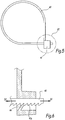
- Figure 5 and 6 provide an illustrative example where the tie 40 includes means to prevent the strap 40 from loosening due to vibration in normal use of the vehicle.
- the extremities 41 and 42 of the strap 40 cooperate one with the other to close the strap 40.
- the extremity 41 of the strap 40 determines a box for receiving the other extremity 42.
- the box 41 is hollow and delimits a passageway for the other extremity 42.
- the extremity 42 is provided with a series of teeth 42a that are adapted to cooperate with a locking tab 44 of the box 41.
- the locking tab 44 is elastically deformable and is engaged between two adjacent teeth 42a. It does not oppose to the strap tightening as it can bend to let the extremity 42 of the strap 40 move along a direction of the passageway. However, the tab 44 is oriented so as to oppose to the displacement of the strap 40 in the opposite direction D2, that is to the strap loosening.
- the self-fastened bracket 1 comprises a L-shaped rigid portion 21 and a flexible arm 26, linked to the first branch 24 of the L-shaped rigid portion 21, and which cooperates with the second branch 22 of the L-shaped rigid portion 21 for clamping on the support structure 60 of the vehicle. It allows securing the self-fastened bracket 1 to the support structure 60 of the vehicle.
- the self-fastened bracket 1 may be made of a synthetic material, e.g. plastic, thermoplastic, polymer or resin, that can be either molded or thermoformed.
- polyacrylamide may be used, in particular polyacrylamide PA66.
- the self-fastened bracket 1 may also comprise metallic elements or metallic alloys or other material that have the suitable flexibility/rigidity for the purpose of the present invention.
- the self-fastened bracket 1 may also be fully made with such a material.
- the flexible arm 26 and the L-shaped rigid portion 21 are preferably made in one-piece.
- the flexible arm 26 and the rigid portion 21 are preferably made in the same material.
- the higher flexibility of the arm 26, compared to the rigid portion 21, may be obtained by decreasing the thickness of the arm 26 with respect to the rigid portion 21.
- the thickness of the arm 26 is advantageously comprised between about 1 mm and about 3 mm, and preferably between 1,7 mm and 2,2 mm.
- the thickness of the rigid portion may be comprised between about 2 mm and about 4 mm, preferably between about 3 mm and about 3,5 mm.
- the ratio between the thickness of the arm 26 and the rigid portion 21 may vary.
- the thickness of the flexible arm 26 is between 10% and 30% less than the thickness of the rigid portion 21. In other words, the thickness of the flexible arm 26 represents 70 to 90% of the thickness of the rigid portion 21. In another specific embodiment, the thickness of the flexible arm 26 represents between 60% and 70% of the thickness of the rigid portion 21. A more flexible arm 26 can be obtained wherein the thickness represents between around 30% and around 50% of the thickness of the rigid portion.
- the thicknesses may be adapted to be in relation with the natural rigidity of the material.
- the flexibility of the arm 26 and the rigid portion 21 refers to their capacity to elastically change their shape under a given force.
- a flexible arm 26 means that the arm 26 is allowed to easily modify its shape under an applied force. Such applied force may be the tightening of the wires or wire harnesses with the tie.
- the rigid portion 21 is meant for a portion the shape of which does not significantly change under a constraint, like the tightening of the wire harnesses with a cable tie.
- the self-fastened bracket 1 is therefore designed in such a way that the flexible arm 26 is elastically deformed by tightening the cable tie 40, whereas the rigid portion 21, including the first branch 24 and the second branch 22, remains substantially straight and non-deformed.
- the articulation 260, linking the flexible arm 26 to the rigid portion 21 is more flexible than the arm 26, thus providing a hinge that allows the flexible arm 26 to rotate with respect to the rigid portion 21.
- the hinge or articulation 260 has a thickness comprised between about 0,3 mm and 1 mm, preferably between about 0,4 mm and 0,5 mm.
- the thickness of the hinge or articulation 260 represents 10% of the thickness of the arm 26.
- the thickness of the hinge or articulation 260 represents between 10% and 25% of the thickness of the arm 26.
- the thickness of the hinge or articulation 260 represents between 30% and 50% of the thickness of the arm 26.
- the directions “up” and “down” have to be considered relative to the configurations of figures 2 and 3 . It is to be understood that this example is not limitative and that the self-fastened bracket 1 may be, for instance, mounted upside down. The self-fastened bracket 1 may also be mounted on a vertical structure.
- the L-shaped rigid portion 21 includes a first branch 24 that extends perpendicularly to the second branch 22 and that delimits two passage openings O24 and O'24 for passing the tie 40. Opening O24 is provided at the end of the branch 24 that is close to the branch 22. The opening O'24 is provided close to the opposite end of the first branch 24. Openings O24 and O'24 are disposed on either side of an extremity of the flexible arm 26 by which it is connected to the L-shaped rigid portion 21. In the configuration of figures 2 and 3 , the first branch 24 extends vertically while the second branch 22 extends horizontally.
- the second branch 22 of the L-shaped rigid portion 21 is adapted to contact the bottom portion of the support structure 60.
- the upper face of the second branch 22 faces the support structure 60 when the self-fastened bracket 1 is mounted onto the support structure 60.
- Said upper face may be provided with grip platelets 220 for increasing grip with the bottom surface of the support structure 60.
- Said upper face may further be provided with a layer of material that increases the grip of the self-fastened bracket.
- Such material may be rubber, elastomer or equivalent material. It can be fixed on the second branch 22 with glue or other equivalent means, or sleeved onto the branch 22, prior the mounting phase on the support 60. Alternatively, said layer of material may be inserted between the second branch 22 of the L-shaped rigid portion 21 and the support structure 60 during the mounting process.
- FIG. 3 shows that the first branch 24 is longer than the second branch 22, others configurations are also possible depending on the specificities of the application. For instance, the length of the second branch 22 may be increased for a better grip on the vehicle structure 60. On the other hand, the length of the first branch 24 has to be adapted to the size of the wire harness.
- the first branch 24 may have an end portion 240 that is curved, or comprise a curve, oriented towards the second branch 22. This allows matching with the circular shape of the wire harness H and improving the contact with the wire harness H so as to reinforce the wire harness clamping.
- the flexible arm 26 may be a flexible tab the extremity of which is attached to the first branch 24 through the articulation 260. More precisely, the flexible arm 26 is attached to a medium portion of the first branch 24, between the openings O24 and O'24.
- the flexible arm 26 comprises a passage opening O26, preferably located near its end that is not linked to the L-shaped rigid portion 21, and which allows the passage of the tie 40.
- the flexible arm 26 is curved.
- the curvature of the flexible arm 26 is in the continuity of, and has the same orientation than, the curvature of the extremity 240 of the first branch 24 of the L-shaped rigid portion 21. As for the branch 24, the curvature of the flexible arm 26 allows matching with the circular shape of the wire harness H.
- the flexible arm 26 is movable by elastic deformation of the attachment point 260, when tightening the wire with the tie 40. This allows squeezing the support structure 60 between the flexible arm 26 and the second branch 22 of the L-shaped rigid portion 21. More precisely, before tightening the wire with the tie 40, the down side of the flexible portion 26 is in contact or in close proximity with the upper side of the support 60. When tightening the wire with the tie 40, the flexible arm 26 comes, in a first step, in contact to the support 60 thanks to the articulation 260, if it is not already in contact, as represented by the arrow A2 on figures 3 and 4 .
- a second step when tightening stronger the wire with the tie 40, the flexible arm 26 is elastically deformed, in such a way that the surface of contact with the support 60 increases, while the strength applied on either side of the support 60 by the second branch 22 of the L-shaped rigid portion and the flexible arm 26 increases. Consequently, thanks to the transmission of the traction effort to the arm 26, the arm 26 exerts an effort E1 on the support structure 60 and the latter is caught up into a vise-like grip formed by the arm 26 and the branch 22 of the bracket 21.
- the tie 40 is tightened at its maximum, the self-fastened bracket 1 and the wire harnesses are solidly fixed onto the support structure 60.
- the first and second step above-described are performed in a continuous way, when tightening the tie 40, thus forming together the unique step of tightening the tie around the wire.
- the self-fastened bracket as such mounted, is able to resist against a pullout force up to around 30 kg.
- the self-fastened bracket 1 mounted with the wire harnesses resists against a pullout force up to around 20 kg, more preferably up to around 10kg.
- the pullout force means any force of traction that induces the sliding of the self-fastened bracket 1 out of the support structure 60.
- the tie 40 that allows securing the wire harnesses onto the first branch 24 of the rigid portion 21 while clamping the flexible arm 26 onto the structure 60, passes through at least the passages O26 and O24, and embraces the wire harnesses H to be secured, by forming a loop.
- the tie 40 may be further guided through an aperture or a passage O'24, provided at the extremity of the first branch 24 of the rigid portion 21.
- the present invention also provides a method of mounting wires, wire harnesses, tubes, pipes and related equipment onto a vehicle, using fixation means that are cheap, light and rapidly mounted.
- the present method aims at limiting the number of steps when mounting the wires on a vehicle, as well as the duration of said steps.
- the present method allows to mount cable, wires, wire harnesses, tubes, or pipes on a vehicle structure avoiding the step of screwing the fixation means on the structure. It is also an aim of the present invention to fix the wire without using tools, meaning that the fixation of the wire is performed by hands.
- the method of the present invention comprises the steps of
- the method of the present invention may further include a step of inserting a grip-improver between the fixation means and the support prior to step a) or concomitant with step a).
- Steps a) and b) above described may be reversed or concomitant, meaning that step b) may be performed prior to step a), or at the same time.
- the fixation means is preferably a device that comprises a flexible arm 26 linked to a rigid portion 21, having a L-shape with a first branch 24 and a second branch 22.
- Said device may be made in a polymerized material, such as a homo polymer or hetero polymer, a molded polymer, a plastic or thermoplastic material.
- the fixation means is preferably made in one piece and is designed or adapted to receive a tie.
- the fixation means used in steps a) to c) comprises a hinge between the flexible arm 26 and the rigid portion 21, in such a way that the flexible arm 26 is articulated with regard to the first branch 24 of the L-shaped rigid portion 21.
- step c) allows grouping the wires, wire harnesses, tubes, pipes or related equipment onto the fixation mean, while securing the fixation means on the support 60, in one and unique step.
- the tightening of the tie in step c) may be performed manually, and may be improved with the help of a tool adapted to tight a tie, such as a dedicated squeezing device.
- the step c) may be optionally followed by the cutting of the extra part of the tie that extends out of the circle VI (see figure 6 ).
- the tie used may be a strip, preferably made in plastic.
- the support of the vehicle may be the chassis, or any other horizontal or vertical rail, or skeleton, or girder that is used to design and/or structure the vehicle.
- the fixation means of steps a) to c) is the self-fastened bracket 1, described herein.
- the present invention provides a novel fixation means adapted for the mounting of wires, wire harnesses, tubes, pipes or related equipment on a vehicle, wherein the fixation means allows to secure said wires, wire harnesses, tubes, pipes or related equipment and to fix the fixation means onto a support at the same time.
- the present invention provides the use of a fixation means that can be manually clamped on a support for mounting wires, wire harnesses, tubes, pipes or related equipment, wherein the fixation means allows the passage of a cable tie.
- the present invention provides the use of a fixation means, wherein the fixation means is the self-fastened bracket 1 hereby described.
Landscapes
- Engineering & Computer Science (AREA)
- General Engineering & Computer Science (AREA)
- Mechanical Engineering (AREA)
- Architecture (AREA)
- Civil Engineering (AREA)
- Structural Engineering (AREA)
- Clamps And Clips (AREA)
- Installation Of Indoor Wiring (AREA)
- Supports For Pipes And Cables (AREA)
Applications Claiming Priority (1)
| Application Number | Priority Date | Filing Date | Title |
|---|---|---|---|
| PCT/EP2014/003136 WO2016082848A1 (en) | 2014-11-25 | 2014-11-25 | Self-fastened bracket for mounting a wire harness to a support structure of a vehicle and vehicle comprising the same |
Publications (2)
| Publication Number | Publication Date |
|---|---|
| EP3224088A1 EP3224088A1 (en) | 2017-10-04 |
| EP3224088B1 true EP3224088B1 (en) | 2019-01-09 |
Family
ID=52130191
Family Applications (1)
| Application Number | Title | Priority Date | Filing Date |
|---|---|---|---|
| EP14815227.5A Active EP3224088B1 (en) | 2014-11-25 | 2014-11-25 | Self-fastened bracket for mounting a wire harness to a support structure of a vehicle and vehicle comprising the same |
Country Status (5)
| Country | Link |
|---|---|
| US (1) | US10207658B2 (ja) |
| EP (1) | EP3224088B1 (ja) |
| JP (1) | JP6535091B2 (ja) |
| CN (1) | CN107000657B (ja) |
| WO (1) | WO2016082848A1 (ja) |
Families Citing this family (19)
| Publication number | Priority date | Publication date | Assignee | Title |
|---|---|---|---|---|
| US11603875B2 (en) * | 2013-12-13 | 2023-03-14 | NTH Innovations, LLC | Connection apparatus for collapsible structures |
| EP3015317B1 (de) * | 2014-10-30 | 2018-12-05 | Nexans | Anordnung zum Befestigen eines langgestreckten Gegenstands in einem Kraftfahrzeug |
| US10076940B2 (en) * | 2015-11-23 | 2018-09-18 | Reyco Granning, Llc | Trailer suspension including tubes and wires support system |
| JP6793047B2 (ja) * | 2017-01-25 | 2020-12-02 | 矢崎総業株式会社 | プロテクタおよびワイヤハーネス |
| JP6792801B2 (ja) * | 2017-07-04 | 2020-12-02 | 住友電装株式会社 | 細長部材の保持構造 |
| JP6626070B2 (ja) * | 2017-11-10 | 2019-12-25 | 矢崎総業株式会社 | ワイヤハーネス |
| US20190190244A1 (en) * | 2017-12-20 | 2019-06-20 | United Technologies Corporation | Harness bracket with cable tie retention features |
| EP3517833A1 (en) * | 2018-01-29 | 2019-07-31 | Valeo Iluminacion | Automotive part, method and apparatus for manufacturing an automotive lighting device and automotive lighting device |
| US10493927B1 (en) | 2018-06-28 | 2019-12-03 | Goodrich Corporation | Managed routing and actuation harness system |
| US10718449B2 (en) * | 2018-08-20 | 2020-07-21 | Spirit Aerosystems, Inc. | Multi-function system support tray |
| CN109163146B (zh) * | 2018-11-07 | 2020-06-16 | 中煤地建设工程有限公司 | 管道安装结构及其安装方法 |
| CN110690001A (zh) * | 2019-09-23 | 2020-01-14 | 国网辽宁省电力有限公司丹东供电公司 | 一种超高压高载流量电缆集群系统 |
| US11865981B2 (en) * | 2020-05-05 | 2024-01-09 | Thor Tech, Inc. | Wire loom support |
| PT116593A (pt) * | 2020-07-21 | 2022-01-21 | C3T Tech Sa | Equipamento de suporte, apoio, acomodação e folga de cabos de telecomunicações |
| JP7266014B2 (ja) * | 2020-08-07 | 2023-04-27 | 住友電装株式会社 | ワイヤハーネスユニット |
| CN112688190B (zh) * | 2021-01-08 | 2022-08-12 | 佛山祥电电力设计工程有限公司 | 一种便于进行应急供电的配电柜结构 |
| CN113525328A (zh) * | 2021-06-30 | 2021-10-22 | 重庆长安汽车股份有限公司 | 一种制动管安装结构 |
| US11677227B2 (en) * | 2021-09-10 | 2023-06-13 | Panduit Corp. | Dual tongue strap cleat bracket |
| CN113876511B (zh) * | 2021-10-13 | 2022-08-30 | 南通市第一人民医院 | 一种护理病房用束线装置 |
Family Cites Families (26)
| Publication number | Priority date | Publication date | Assignee | Title |
|---|---|---|---|---|
| US2373833A (en) * | 1943-08-24 | 1945-04-17 | United Carr Fastener Corp | Cable clamp |
| US3087700A (en) * | 1960-10-31 | 1963-04-30 | John A Carpenter | Cable support |
| US3113754A (en) | 1962-09-18 | 1963-12-10 | United Carr Fastener Corp | Wiring clip |
| JPH0242943Y2 (ja) | 1986-12-26 | 1990-11-15 | ||
| US5354021A (en) * | 1994-01-04 | 1994-10-11 | Farrell Darvel B | An adjustable clamp |
| US5662399A (en) | 1995-09-01 | 1997-09-02 | Doxey Furniture Corporation | Ready-to-assemble cabinet |
| US5730399A (en) * | 1996-02-21 | 1998-03-24 | Volvo Gm Heavy Truck Corporation | Method and assembly for mounting service lines |
| US5639049A (en) * | 1996-05-08 | 1997-06-17 | Jennings; Gilbert M. | Compact cable clip for retainment of cables and tubing |
| JP2000014763A (ja) | 1998-06-26 | 2000-01-18 | Nippon Electric Glass Co Ltd | 生体活性セメント組成物 |
| JP2000023335A (ja) | 1998-07-01 | 2000-01-21 | Sumitomo Wiring Syst Ltd | クリップ |
| JP2000134763A (ja) * | 1998-10-22 | 2000-05-12 | Sumitomo Wiring Syst Ltd | ワイヤハーネス用プロテクタへのクランプ取付構造 |
| US7134633B2 (en) | 2004-02-05 | 2006-11-14 | Medcount Systems, L.L.C. | Method and apparatus for securing cables and the like |
| JP4337979B2 (ja) | 2004-09-13 | 2009-09-30 | 株式会社ニックス | 長尺体保持具 |
| US7407138B1 (en) * | 2005-01-24 | 2008-08-05 | Arlington Industries, Inc. | Gangable cable support with improved stiffness |
| US7712708B2 (en) * | 2006-06-05 | 2010-05-11 | Illinios Tool Works Inc. | Fastener clip |
| WO2009082292A1 (en) | 2007-12-21 | 2009-07-02 | Volvo Lastvagnar Ab | A clip device, a system for attachment of conduits comprising said clip device as well as a heavy vehicle comprising said clip device and/or system |
| JP5510064B2 (ja) | 2010-05-24 | 2014-06-04 | 住友電装株式会社 | ワイヤハーネス用のプロテクタ |
| US8616512B2 (en) * | 2010-09-23 | 2013-12-31 | Illinois Tool Works Inc. | Multi-purpose cable support having bendable stem |
| JP2012095434A (ja) | 2010-10-26 | 2012-05-17 | Sumitomo Wiring Syst Ltd | バンドクリップ |
| JP2012253909A (ja) | 2011-06-03 | 2012-12-20 | Daiwa Kasei Kogyo Kk | ベルトクランプ |
| US8991774B2 (en) * | 2011-12-22 | 2015-03-31 | Panduit Corp. | Cable tie mount |
| US9033288B2 (en) | 2012-05-02 | 2015-05-19 | Johnson Controls Technology Company | System and method for mounting a wire harness within a vehicle interior |
| GB201220289D0 (en) * | 2012-11-12 | 2012-12-26 | Airbus Operations Ltd | A mount for a cable harness |
| JP2015200363A (ja) * | 2014-04-08 | 2015-11-12 | キャタピラー エス エー アール エル | 長尺物保持具 |
| WO2015193841A1 (en) * | 2014-06-20 | 2015-12-23 | Lake Products Limited | A multi-fit clip |
| TWI573361B (zh) * | 2015-07-21 | 2017-03-01 | 鴻海精密工業股份有限公司 | 固定裝置 |
-
2014
- 2014-11-25 EP EP14815227.5A patent/EP3224088B1/en active Active
- 2014-11-25 US US15/528,672 patent/US10207658B2/en active Active
- 2014-11-25 JP JP2017528152A patent/JP6535091B2/ja not_active Expired - Fee Related
- 2014-11-25 CN CN201480083671.7A patent/CN107000657B/zh active Active
- 2014-11-25 WO PCT/EP2014/003136 patent/WO2016082848A1/en active Application Filing
Non-Patent Citations (1)
| Title |
|---|
| None * |
Also Published As
| Publication number | Publication date |
|---|---|
| CN107000657A (zh) | 2017-08-01 |
| JP6535091B2 (ja) | 2019-06-26 |
| EP3224088A1 (en) | 2017-10-04 |
| US10207658B2 (en) | 2019-02-19 |
| JP2017538077A (ja) | 2017-12-21 |
| US20170267191A1 (en) | 2017-09-21 |
| CN107000657B (zh) | 2020-08-11 |
| WO2016082848A1 (en) | 2016-06-02 |
Similar Documents
| Publication | Publication Date | Title |
|---|---|---|
| EP3224088B1 (en) | Self-fastened bracket for mounting a wire harness to a support structure of a vehicle and vehicle comprising the same | |
| US8157222B1 (en) | Wire harness clamp | |
| US6508442B1 (en) | Mounting clamp for a tubular part | |
| US9254908B2 (en) | Fixing means | |
| US6830075B1 (en) | Hose assembly with integrally molded brake hose bracket | |
| JP2005524578A (ja) | 横支持体 | |
| WO2014188781A1 (ja) | 自動二輪車のハーネス支持構造 | |
| CN202371303U (zh) | 一种管夹 | |
| WO2009082292A1 (en) | A clip device, a system for attachment of conduits comprising said clip device as well as a heavy vehicle comprising said clip device and/or system | |
| WO2014193351A1 (en) | Harness clip and system for clipping wiring harness | |
| CN105620389B (zh) | 机动车辆中固定细长物体的装置 | |
| US8723045B2 (en) | Assembly for securing a wire harness to a sensor coupler | |
| US9783175B2 (en) | Cable mounting assembly | |
| JP2009270686A (ja) | 配索部材の保持具 | |
| KR20190074526A (ko) | 회전 방지 기능이 구비된 밴드 케이블을 이용한 와이어링 하네스 고정 장치 | |
| JP4201523B2 (ja) | ケーブルの複合クランプおよびクランプ方法 | |
| KR100427986B1 (ko) | 차량의 전선하네스 고정구조 | |
| CN216886884U (zh) | 一种悬空管路通用固定支架 | |
| FR2967621B1 (fr) | Goulotte de guidage de cables pour le montage de vehicules automobiles | |
| KR20170086184A (ko) | 장탈착이 견고한 와이어 하네스 고정구 | |
| CN206841350U (zh) | 排线固定夹和具有其的车辆 | |
| DE102010007983A1 (de) | Befestigungsvorrichtung zur Befestigung eines Rundprofilelements an einem Rundprofilträger | |
| RU36314U1 (ru) | Устройство крепления электронного прибора автомобиля | |
| KR200408584Y1 (ko) | 자동차용 배선 고정용 밴드케이블 | |
| KR20170015740A (ko) | 자동차용 헤드 라이닝의 배선 장착용 고정구 |
Legal Events
| Date | Code | Title | Description |
|---|---|---|---|
| STAA | Information on the status of an ep patent application or granted ep patent |
Free format text: STATUS: THE INTERNATIONAL PUBLICATION HAS BEEN MADE |
|
| PUAI | Public reference made under article 153(3) epc to a published international application that has entered the european phase |
Free format text: ORIGINAL CODE: 0009012 |
|
| STAA | Information on the status of an ep patent application or granted ep patent |
Free format text: STATUS: REQUEST FOR EXAMINATION WAS MADE |
|
| 17P | Request for examination filed |
Effective date: 20170608 |
|
| AK | Designated contracting states |
Kind code of ref document: A1 Designated state(s): AL AT BE BG CH CY CZ DE DK EE ES FI FR GB GR HR HU IE IS IT LI LT LU LV MC MK MT NL NO PL PT RO RS SE SI SK SM TR |
|
| AX | Request for extension of the european patent |
Extension state: BA ME |
|
| DAX | Request for extension of the european patent (deleted) | ||
| STAA | Information on the status of an ep patent application or granted ep patent |
Free format text: STATUS: EXAMINATION IS IN PROGRESS |
|
| 17Q | First examination report despatched |
Effective date: 20180308 |
|
| GRAP | Despatch of communication of intention to grant a patent |
Free format text: ORIGINAL CODE: EPIDOSNIGR1 |
|
| STAA | Information on the status of an ep patent application or granted ep patent |
Free format text: STATUS: GRANT OF PATENT IS INTENDED |
|
| INTG | Intention to grant announced |
Effective date: 20180806 |
|
| RAP1 | Party data changed (applicant data changed or rights of an application transferred) |
Owner name: VOLVO TRUCK CORPORATION |
|
| GRAS | Grant fee paid |
Free format text: ORIGINAL CODE: EPIDOSNIGR3 |
|
| GRAA | (expected) grant |
Free format text: ORIGINAL CODE: 0009210 |
|
| STAA | Information on the status of an ep patent application or granted ep patent |
Free format text: STATUS: THE PATENT HAS BEEN GRANTED |
|
| AK | Designated contracting states |
Kind code of ref document: B1 Designated state(s): AL AT BE BG CH CY CZ DE DK EE ES FI FR GB GR HR HU IE IS IT LI LT LU LV MC MK MT NL NO PL PT RO RS SE SI SK SM TR |
|
| REG | Reference to a national code |
Ref country code: GB Ref legal event code: FG4D |
|
| REG | Reference to a national code |
Ref country code: CH Ref legal event code: EP Ref country code: AT Ref legal event code: REF Ref document number: 1086872 Country of ref document: AT Kind code of ref document: T Effective date: 20190115 |
|
| REG | Reference to a national code |
Ref country code: IE Ref legal event code: FG4D |
|
| REG | Reference to a national code |
Ref country code: DE Ref legal event code: R096 Ref document number: 602014039702 Country of ref document: DE |
|
| REG | Reference to a national code |
Ref country code: SE Ref legal event code: TRGR |
|
| REG | Reference to a national code |
Ref country code: NL Ref legal event code: MP Effective date: 20190109 |
|
| REG | Reference to a national code |
Ref country code: LT Ref legal event code: MG4D |
|
| PG25 | Lapsed in a contracting state [announced via postgrant information from national office to epo] |
Ref country code: NL Free format text: LAPSE BECAUSE OF FAILURE TO SUBMIT A TRANSLATION OF THE DESCRIPTION OR TO PAY THE FEE WITHIN THE PRESCRIBED TIME-LIMIT Effective date: 20190109 |
|
| REG | Reference to a national code |
Ref country code: AT Ref legal event code: MK05 Ref document number: 1086872 Country of ref document: AT Kind code of ref document: T Effective date: 20190109 |
|
| PG25 | Lapsed in a contracting state [announced via postgrant information from national office to epo] |
Ref country code: PT Free format text: LAPSE BECAUSE OF FAILURE TO SUBMIT A TRANSLATION OF THE DESCRIPTION OR TO PAY THE FEE WITHIN THE PRESCRIBED TIME-LIMIT Effective date: 20190509 Ref country code: FI Free format text: LAPSE BECAUSE OF FAILURE TO SUBMIT A TRANSLATION OF THE DESCRIPTION OR TO PAY THE FEE WITHIN THE PRESCRIBED TIME-LIMIT Effective date: 20190109 Ref country code: NO Free format text: LAPSE BECAUSE OF FAILURE TO SUBMIT A TRANSLATION OF THE DESCRIPTION OR TO PAY THE FEE WITHIN THE PRESCRIBED TIME-LIMIT Effective date: 20190409 Ref country code: PL Free format text: LAPSE BECAUSE OF FAILURE TO SUBMIT A TRANSLATION OF THE DESCRIPTION OR TO PAY THE FEE WITHIN THE PRESCRIBED TIME-LIMIT Effective date: 20190109 Ref country code: LT Free format text: LAPSE BECAUSE OF FAILURE TO SUBMIT A TRANSLATION OF THE DESCRIPTION OR TO PAY THE FEE WITHIN THE PRESCRIBED TIME-LIMIT Effective date: 20190109 Ref country code: ES Free format text: LAPSE BECAUSE OF FAILURE TO SUBMIT A TRANSLATION OF THE DESCRIPTION OR TO PAY THE FEE WITHIN THE PRESCRIBED TIME-LIMIT Effective date: 20190109 |
|
| PG25 | Lapsed in a contracting state [announced via postgrant information from national office to epo] |
Ref country code: IS Free format text: LAPSE BECAUSE OF FAILURE TO SUBMIT A TRANSLATION OF THE DESCRIPTION OR TO PAY THE FEE WITHIN THE PRESCRIBED TIME-LIMIT Effective date: 20190509 Ref country code: HR Free format text: LAPSE BECAUSE OF FAILURE TO SUBMIT A TRANSLATION OF THE DESCRIPTION OR TO PAY THE FEE WITHIN THE PRESCRIBED TIME-LIMIT Effective date: 20190109 Ref country code: LV Free format text: LAPSE BECAUSE OF FAILURE TO SUBMIT A TRANSLATION OF THE DESCRIPTION OR TO PAY THE FEE WITHIN THE PRESCRIBED TIME-LIMIT Effective date: 20190109 Ref country code: GR Free format text: LAPSE BECAUSE OF FAILURE TO SUBMIT A TRANSLATION OF THE DESCRIPTION OR TO PAY THE FEE WITHIN THE PRESCRIBED TIME-LIMIT Effective date: 20190410 Ref country code: BG Free format text: LAPSE BECAUSE OF FAILURE TO SUBMIT A TRANSLATION OF THE DESCRIPTION OR TO PAY THE FEE WITHIN THE PRESCRIBED TIME-LIMIT Effective date: 20190409 Ref country code: RS Free format text: LAPSE BECAUSE OF FAILURE TO SUBMIT A TRANSLATION OF THE DESCRIPTION OR TO PAY THE FEE WITHIN THE PRESCRIBED TIME-LIMIT Effective date: 20190109 |
|
| REG | Reference to a national code |
Ref country code: DE Ref legal event code: R097 Ref document number: 602014039702 Country of ref document: DE |
|
| PG25 | Lapsed in a contracting state [announced via postgrant information from national office to epo] |
Ref country code: CZ Free format text: LAPSE BECAUSE OF FAILURE TO SUBMIT A TRANSLATION OF THE DESCRIPTION OR TO PAY THE FEE WITHIN THE PRESCRIBED TIME-LIMIT Effective date: 20190109 Ref country code: IT Free format text: LAPSE BECAUSE OF FAILURE TO SUBMIT A TRANSLATION OF THE DESCRIPTION OR TO PAY THE FEE WITHIN THE PRESCRIBED TIME-LIMIT Effective date: 20190109 Ref country code: RO Free format text: LAPSE BECAUSE OF FAILURE TO SUBMIT A TRANSLATION OF THE DESCRIPTION OR TO PAY THE FEE WITHIN THE PRESCRIBED TIME-LIMIT Effective date: 20190109 Ref country code: EE Free format text: LAPSE BECAUSE OF FAILURE TO SUBMIT A TRANSLATION OF THE DESCRIPTION OR TO PAY THE FEE WITHIN THE PRESCRIBED TIME-LIMIT Effective date: 20190109 Ref country code: AT Free format text: LAPSE BECAUSE OF FAILURE TO SUBMIT A TRANSLATION OF THE DESCRIPTION OR TO PAY THE FEE WITHIN THE PRESCRIBED TIME-LIMIT Effective date: 20190109 Ref country code: DK Free format text: LAPSE BECAUSE OF FAILURE TO SUBMIT A TRANSLATION OF THE DESCRIPTION OR TO PAY THE FEE WITHIN THE PRESCRIBED TIME-LIMIT Effective date: 20190109 Ref country code: SK Free format text: LAPSE BECAUSE OF FAILURE TO SUBMIT A TRANSLATION OF THE DESCRIPTION OR TO PAY THE FEE WITHIN THE PRESCRIBED TIME-LIMIT Effective date: 20190109 Ref country code: AL Free format text: LAPSE BECAUSE OF FAILURE TO SUBMIT A TRANSLATION OF THE DESCRIPTION OR TO PAY THE FEE WITHIN THE PRESCRIBED TIME-LIMIT Effective date: 20190109 |
|
| PLBE | No opposition filed within time limit |
Free format text: ORIGINAL CODE: 0009261 |
|
| STAA | Information on the status of an ep patent application or granted ep patent |
Free format text: STATUS: NO OPPOSITION FILED WITHIN TIME LIMIT |
|
| PG25 | Lapsed in a contracting state [announced via postgrant information from national office to epo] |
Ref country code: SM Free format text: LAPSE BECAUSE OF FAILURE TO SUBMIT A TRANSLATION OF THE DESCRIPTION OR TO PAY THE FEE WITHIN THE PRESCRIBED TIME-LIMIT Effective date: 20190109 |
|
| 26N | No opposition filed |
Effective date: 20191010 |
|
| PGFP | Annual fee paid to national office [announced via postgrant information from national office to epo] |
Ref country code: DE Payment date: 20191129 Year of fee payment: 6 Ref country code: SE Payment date: 20191125 Year of fee payment: 6 |
|
| PG25 | Lapsed in a contracting state [announced via postgrant information from national office to epo] |
Ref country code: SI Free format text: LAPSE BECAUSE OF FAILURE TO SUBMIT A TRANSLATION OF THE DESCRIPTION OR TO PAY THE FEE WITHIN THE PRESCRIBED TIME-LIMIT Effective date: 20190109 |
|
| PG25 | Lapsed in a contracting state [announced via postgrant information from national office to epo] |
Ref country code: TR Free format text: LAPSE BECAUSE OF FAILURE TO SUBMIT A TRANSLATION OF THE DESCRIPTION OR TO PAY THE FEE WITHIN THE PRESCRIBED TIME-LIMIT Effective date: 20190109 |
|
| REG | Reference to a national code |
Ref country code: CH Ref legal event code: PL |
|
| PG25 | Lapsed in a contracting state [announced via postgrant information from national office to epo] |
Ref country code: CH Free format text: LAPSE BECAUSE OF NON-PAYMENT OF DUE FEES Effective date: 20191130 Ref country code: LU Free format text: LAPSE BECAUSE OF NON-PAYMENT OF DUE FEES Effective date: 20191125 Ref country code: LI Free format text: LAPSE BECAUSE OF NON-PAYMENT OF DUE FEES Effective date: 20191130 Ref country code: MC Free format text: LAPSE BECAUSE OF FAILURE TO SUBMIT A TRANSLATION OF THE DESCRIPTION OR TO PAY THE FEE WITHIN THE PRESCRIBED TIME-LIMIT Effective date: 20190109 |
|
| REG | Reference to a national code |
Ref country code: BE Ref legal event code: MM Effective date: 20191130 |
|
| GBPC | Gb: european patent ceased through non-payment of renewal fee |
Effective date: 20191125 |
|
| PG25 | Lapsed in a contracting state [announced via postgrant information from national office to epo] |
Ref country code: IE Free format text: LAPSE BECAUSE OF NON-PAYMENT OF DUE FEES Effective date: 20191125 Ref country code: GB Free format text: LAPSE BECAUSE OF NON-PAYMENT OF DUE FEES Effective date: 20191125 |
|
| PG25 | Lapsed in a contracting state [announced via postgrant information from national office to epo] |
Ref country code: BE Free format text: LAPSE BECAUSE OF NON-PAYMENT OF DUE FEES Effective date: 20191130 |
|
| PG25 | Lapsed in a contracting state [announced via postgrant information from national office to epo] |
Ref country code: CY Free format text: LAPSE BECAUSE OF FAILURE TO SUBMIT A TRANSLATION OF THE DESCRIPTION OR TO PAY THE FEE WITHIN THE PRESCRIBED TIME-LIMIT Effective date: 20190109 |
|
| REG | Reference to a national code |
Ref country code: DE Ref legal event code: R119 Ref document number: 602014039702 Country of ref document: DE |
|
| REG | Reference to a national code |
Ref country code: SE Ref legal event code: EUG |
|
| PG25 | Lapsed in a contracting state [announced via postgrant information from national office to epo] |
Ref country code: MT Free format text: LAPSE BECAUSE OF FAILURE TO SUBMIT A TRANSLATION OF THE DESCRIPTION OR TO PAY THE FEE WITHIN THE PRESCRIBED TIME-LIMIT Effective date: 20190109 Ref country code: HU Free format text: LAPSE BECAUSE OF FAILURE TO SUBMIT A TRANSLATION OF THE DESCRIPTION OR TO PAY THE FEE WITHIN THE PRESCRIBED TIME-LIMIT; INVALID AB INITIO Effective date: 20141125 |
|
| PG25 | Lapsed in a contracting state [announced via postgrant information from national office to epo] |
Ref country code: SE Free format text: LAPSE BECAUSE OF NON-PAYMENT OF DUE FEES Effective date: 20201126 |
|
| PG25 | Lapsed in a contracting state [announced via postgrant information from national office to epo] |
Ref country code: DE Free format text: LAPSE BECAUSE OF NON-PAYMENT OF DUE FEES Effective date: 20210601 |
|
| PG25 | Lapsed in a contracting state [announced via postgrant information from national office to epo] |
Ref country code: MK Free format text: LAPSE BECAUSE OF FAILURE TO SUBMIT A TRANSLATION OF THE DESCRIPTION OR TO PAY THE FEE WITHIN THE PRESCRIBED TIME-LIMIT Effective date: 20190109 |
|
| PGFP | Annual fee paid to national office [announced via postgrant information from national office to epo] |
Ref country code: FR Payment date: 20231123 Year of fee payment: 10 |