EP3222222B1 - Turning control mechanism and surgical instrument having turning control mechanism - Google Patents
Turning control mechanism and surgical instrument having turning control mechanism Download PDFInfo
- Publication number
- EP3222222B1 EP3222222B1 EP15878587.3A EP15878587A EP3222222B1 EP 3222222 B1 EP3222222 B1 EP 3222222B1 EP 15878587 A EP15878587 A EP 15878587A EP 3222222 B1 EP3222222 B1 EP 3222222B1
- Authority
- EP
- European Patent Office
- Prior art keywords
- angle
- wrench
- turning
- cam lock
- control mechanism
- Prior art date
- Legal status (The legal status is an assumption and is not a legal conclusion. Google has not performed a legal analysis and makes no representation as to the accuracy of the status listed.)
- Active
Links
- 230000007246 mechanism Effects 0.000 title claims description 142
- 230000005540 biological transmission Effects 0.000 claims description 41
- 238000005452 bending Methods 0.000 claims description 37
- 238000007906 compression Methods 0.000 claims description 27
- 230000006835 compression Effects 0.000 claims description 25
- 210000000683 abdominal cavity Anatomy 0.000 description 3
- 210000000115 thoracic cavity Anatomy 0.000 description 3
- 230000003872 anastomosis Effects 0.000 description 2
- 238000010586 diagram Methods 0.000 description 2
- 238000009826 distribution Methods 0.000 description 2
- 238000002674 endoscopic surgery Methods 0.000 description 2
- 210000004888 thoracic abdominal cavity Anatomy 0.000 description 2
- 210000001015 abdomen Anatomy 0.000 description 1
- 230000009471 action Effects 0.000 description 1
- 230000009286 beneficial effect Effects 0.000 description 1
- 210000000038 chest Anatomy 0.000 description 1
- 238000005520 cutting process Methods 0.000 description 1
- 230000007547 defect Effects 0.000 description 1
- 238000005516 engineering process Methods 0.000 description 1
- 238000000338 in vitro Methods 0.000 description 1
- 238000001746 injection moulding Methods 0.000 description 1
- 238000004519 manufacturing process Methods 0.000 description 1
- 239000002184 metal Substances 0.000 description 1
- 230000004048 modification Effects 0.000 description 1
- 238000012986 modification Methods 0.000 description 1
- 238000000465 moulding Methods 0.000 description 1
- 210000000056 organ Anatomy 0.000 description 1
- 239000000126 substance Substances 0.000 description 1
Images

Classifications
-
- A—HUMAN NECESSITIES
- A61—MEDICAL OR VETERINARY SCIENCE; HYGIENE
- A61B—DIAGNOSIS; SURGERY; IDENTIFICATION
- A61B17/00—Surgical instruments, devices or methods, e.g. tourniquets
- A61B17/068—Surgical staplers, e.g. containing multiple staples or clamps
- A61B17/072—Surgical staplers, e.g. containing multiple staples or clamps for applying a row of staples in a single action, e.g. the staples being applied simultaneously
- A61B17/07207—Surgical staplers, e.g. containing multiple staples or clamps for applying a row of staples in a single action, e.g. the staples being applied simultaneously the staples being applied sequentially
-
- A—HUMAN NECESSITIES
- A61—MEDICAL OR VETERINARY SCIENCE; HYGIENE
- A61B—DIAGNOSIS; SURGERY; IDENTIFICATION
- A61B17/00—Surgical instruments, devices or methods, e.g. tourniquets
- A61B17/00234—Surgical instruments, devices or methods, e.g. tourniquets for minimally invasive surgery
-
- A—HUMAN NECESSITIES
- A61—MEDICAL OR VETERINARY SCIENCE; HYGIENE
- A61B—DIAGNOSIS; SURGERY; IDENTIFICATION
- A61B17/00—Surgical instruments, devices or methods, e.g. tourniquets
- A61B17/068—Surgical staplers, e.g. containing multiple staples or clamps
-
- A—HUMAN NECESSITIES
- A61—MEDICAL OR VETERINARY SCIENCE; HYGIENE
- A61B—DIAGNOSIS; SURGERY; IDENTIFICATION
- A61B90/00—Instruments, implements or accessories specially adapted for surgery or diagnosis and not covered by any of the groups A61B1/00 - A61B50/00, e.g. for luxation treatment or for protecting wound edges
- A61B90/03—Automatic limiting or abutting means, e.g. for safety
-
- A—HUMAN NECESSITIES
- A61—MEDICAL OR VETERINARY SCIENCE; HYGIENE
- A61B—DIAGNOSIS; SURGERY; IDENTIFICATION
- A61B17/00—Surgical instruments, devices or methods, e.g. tourniquets
- A61B17/068—Surgical staplers, e.g. containing multiple staples or clamps
- A61B17/072—Surgical staplers, e.g. containing multiple staples or clamps for applying a row of staples in a single action, e.g. the staples being applied simultaneously
-
- A—HUMAN NECESSITIES
- A61—MEDICAL OR VETERINARY SCIENCE; HYGIENE
- A61B—DIAGNOSIS; SURGERY; IDENTIFICATION
- A61B17/00—Surgical instruments, devices or methods, e.g. tourniquets
- A61B2017/00017—Electrical control of surgical instruments
-
- A—HUMAN NECESSITIES
- A61—MEDICAL OR VETERINARY SCIENCE; HYGIENE
- A61B—DIAGNOSIS; SURGERY; IDENTIFICATION
- A61B17/00—Surgical instruments, devices or methods, e.g. tourniquets
- A61B17/00234—Surgical instruments, devices or methods, e.g. tourniquets for minimally invasive surgery
- A61B2017/00238—Type of minimally invasive operation
-
- A—HUMAN NECESSITIES
- A61—MEDICAL OR VETERINARY SCIENCE; HYGIENE
- A61B—DIAGNOSIS; SURGERY; IDENTIFICATION
- A61B17/00—Surgical instruments, devices or methods, e.g. tourniquets
- A61B17/00234—Surgical instruments, devices or methods, e.g. tourniquets for minimally invasive surgery
- A61B2017/00292—Surgical instruments, devices or methods, e.g. tourniquets for minimally invasive surgery mounted on or guided by flexible, e.g. catheter-like, means
- A61B2017/003—Steerable
- A61B2017/00318—Steering mechanisms
-
- A—HUMAN NECESSITIES
- A61—MEDICAL OR VETERINARY SCIENCE; HYGIENE
- A61B—DIAGNOSIS; SURGERY; IDENTIFICATION
- A61B17/00—Surgical instruments, devices or methods, e.g. tourniquets
- A61B2017/00367—Details of actuation of instruments, e.g. relations between pushing buttons, or the like, and activation of the tool, working tip, or the like
- A61B2017/00407—Ratchet means
-
- A—HUMAN NECESSITIES
- A61—MEDICAL OR VETERINARY SCIENCE; HYGIENE
- A61B—DIAGNOSIS; SURGERY; IDENTIFICATION
- A61B17/00—Surgical instruments, devices or methods, e.g. tourniquets
- A61B17/068—Surgical staplers, e.g. containing multiple staples or clamps
- A61B17/072—Surgical staplers, e.g. containing multiple staples or clamps for applying a row of staples in a single action, e.g. the staples being applied simultaneously
- A61B2017/07214—Stapler heads
-
- A—HUMAN NECESSITIES
- A61—MEDICAL OR VETERINARY SCIENCE; HYGIENE
- A61B—DIAGNOSIS; SURGERY; IDENTIFICATION
- A61B17/00—Surgical instruments, devices or methods, e.g. tourniquets
- A61B17/28—Surgical forceps
- A61B17/29—Forceps for use in minimally invasive surgery
- A61B17/2909—Handles
- A61B2017/2912—Handles transmission of forces to actuating rod or piston
- A61B2017/2923—Toothed members, e.g. rack and pinion
-
- A—HUMAN NECESSITIES
- A61—MEDICAL OR VETERINARY SCIENCE; HYGIENE
- A61B—DIAGNOSIS; SURGERY; IDENTIFICATION
- A61B17/00—Surgical instruments, devices or methods, e.g. tourniquets
- A61B17/28—Surgical forceps
- A61B17/29—Forceps for use in minimally invasive surgery
- A61B2017/2926—Details of heads or jaws
- A61B2017/2927—Details of heads or jaws the angular position of the head being adjustable with respect to the shaft
-
- A—HUMAN NECESSITIES
- A61—MEDICAL OR VETERINARY SCIENCE; HYGIENE
- A61B—DIAGNOSIS; SURGERY; IDENTIFICATION
- A61B90/00—Instruments, implements or accessories specially adapted for surgery or diagnosis and not covered by any of the groups A61B1/00 - A61B50/00, e.g. for luxation treatment or for protecting wound edges
- A61B90/03—Automatic limiting or abutting means, e.g. for safety
- A61B2090/033—Abutting means, stops, e.g. abutting on tissue or skin
- A61B2090/034—Abutting means, stops, e.g. abutting on tissue or skin abutting on parts of the device itself
- A61B2090/035—Abutting means, stops, e.g. abutting on tissue or skin abutting on parts of the device itself preventing further rotation
-
- A—HUMAN NECESSITIES
- A61—MEDICAL OR VETERINARY SCIENCE; HYGIENE
- A61B—DIAGNOSIS; SURGERY; IDENTIFICATION
- A61B90/00—Instruments, implements or accessories specially adapted for surgery or diagnosis and not covered by any of the groups A61B1/00 - A61B50/00, e.g. for luxation treatment or for protecting wound edges
- A61B90/03—Automatic limiting or abutting means, e.g. for safety
- A61B2090/033—Abutting means, stops, e.g. abutting on tissue or skin
- A61B2090/036—Abutting means, stops, e.g. abutting on tissue or skin abutting on tissue or skin
Definitions
- the invention relates to a bending control mechanism for surgical stapler, in particular to a mechanism for controlling turning and locking of the jaws of the endoscopic stapler.
- a bending control mechanism comprising the following devices: a wrench constituting a turning power input mechanism A and a lifting ring which synchronously rotates with the wrench; a central shaft constituting a turning transmission mechanism B; a cam lock, a compression spring and a rotating head constituting a locking mechanism C, wherein the cam lock is engaged with the turning transmission mechanism B; a linear power output mechanism D; wherein:
- the invention also relates to a surgical instrument comprising such bending control mechanism.
- Document EP 2 484 290 A1 discloses a bending control mechanism of the generic type specified above, and a surgical instrument comprising the same.
- Document EP 0 807 409 A1 discloses an articulation transmission mechanism and a surgical instrument comprising the same, wherein a linear power output mechanism is constituted by toothed racks meshing with a gear arranged on a central shaft.
- the action principle of surgical stapler is as follows: two corresponding jaws (commonly referred to as anvil assembly and cartridge assembly) are closed to clamp tissue; and then metal suturing nails in cartridge of the stapler are pushed out to perform molding, to sew tissue together. Some staplers are provided with a cutting knife, to cut off the sewn tissue together.
- the traditional mode of operation is gradually turned into the endoscopic surgery.
- endoscopic surgery a number of small incisions with diameter of 5-12 mm are made in different parts of the abdomen or chest; camera lens and a variety of special surgical instruments are inserted in these small incisions; images of various organs in the abdominal cavity taken by the camera inserted in the abdominal cavity are transmitted to the TV screen; by observing the images, the surgeon operates a variety of surgical instruments to complete the operation.
- the endoscopic stapler plays the most crucial role in the operation. Due to the limitation of space in the abdominal cavity or thoracic cavity, in some extreme cases, the traditional linear endoscopic stapler cannot effectively reach the surgical site to perform clamping, transection and anastomosis of tissue; therefore, an elbow stapler with stapler jaw (including anvil assembly and cartridge assembly) capable of turning is required.
- this kind of elbow stapler capable of turning enters the thoracic cavity or abdominal cavity through puncture outfit; the jaw is controlled by the bending control mechanism on the in-vitro handle to bend to a certain angle; and a series of operations such as clamping, transection and anastomosis are performed on the surgical site. After the operation is completed, the elbow stapler exits the body after turning to the straight line state.
- an object of the invention is to design a simple control mechanism, to reach the purpose of making the stapler jaw turn by pulling the wrench, and lock the stapler jaw at the selected angle.
- a bending control mechanism comprises the following devices: a wrench constituting a turning power input mechanism A and a lifting ring which synchronously rotates with the wrench; a central shaft constituting a turning transmission mechanism B; a cam lock, a compression spring and a rotating head constituting a locking mechanism C, wherein the cam lock is engaged with the turning transmission mechanism B; and a linear power output mechanism D, wherein further: the turning power input mechanism A and the turning transmission mechanism B which are coaxially arranged have a relative rotating angle range in a circumferential direction; the turning power input mechanism A sequentially rotates from an angle I, through an angle range II, to an angle III while rotating relative to the turning transmission mechanism B from one end angle to another end angle within a relative rotating angle range; when the turning power input mechanism A is within the angle range II, the cam lock driven by the compression spring is locked at the rotating head in meshing manner to lock the turning transmission mechanism B, so that the turning transmission mechanism B and linear power output mechanism D remain stationary; when the turning power input mechanism A is at the angle
- the linear power output mechanism D is constituted by a rack, wherein the rack is engaged with a gear arranged on the central shaft; a pin hole of the wrench is matched with a fan-shaped hole of the central shaft via a pin; an angle of the fan-shaped hole composes said relative rotating angle range; the wrench extends downwards by means of a boss; the lifting ring is provided with a wrench fitting groove; and the boss is engaged in the wrench fitting groove.
- the angle range between the angle I and the angle III composes said angle range II.
- a plurality of engagement locked positions are arranged at the opening of the rotating head in the circumferential direction; along with rotation of the cam lock, the rotating head can be meshed to the corresponding engagement locked position by the cam lock.
- said wrench when the pin is located at one end of the fan-shaped hole, said wrench is at the angle I; when the pin is located at the other end of the fan-shaped hole, said wrench is at the angle III; when the pin is located between one end and the other end of the fan-shaped hole, said wrench is within the angle range II.
- the lifting ring is provided with a drive ramp;
- the cam lock is provided with a driven ramp, and the driven ramp is matched in the drive ramp; when the lifting ring driven by the wrench rotates within the angle range II, there is a relative rotation between the lifting ring and the cam lock; when the lifting ring driven by the wrench rotates to the angle I and angle III, the driven ramp is driven by the drive ramp, so that the cam lock is away from the rotating head, to separate from the engagement locking with the rotating head.
- the wrench is provided with a cover plate; the cam lock is provided with a compression spring support surface; a compression spring is connected between the cover plate and the compression spring support surface.
- a limit boss is arranged at the opening of the rotating head; and an angle limiting groove matched with the limit boss is arranged on said wrench.
- a surgical instrument with a bending control mechanism according to the invention comprises the above-mentioned bending control mechanism.
- said surgical instrument is a surgical stapler; the linear power output mechanism D of said bending control mechanism is connected to the jaws of the stapler.
- the invention has the following beneficial effects:
- the invention provides a surgical instrument with bending control mechanism, comprising a bending control mechanism.
- Said surgical instrument is a surgical stapler; the linear power output mechanism D of said bending control mechanism is connected to the jaws of the stapler.
- the invention provides an endoscopic surgical stapler with bending control mechanism.
- the endoscopic surgical stapler comprises a tubular structure; the tubular structure is provided with stapler jaw at the remote end, and the near end is connected to the bending control mechanism.
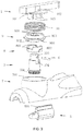
- FIG. 2 shows the bending control mechanism in the invention; said bending control mechanism comprises a wrench 1 and an upper part of rotating head 7, wherein the wrench 1 is installed on the upper part of rotating head 7.
- said bending control mechanism comprises a wrench constituting turning power input mechanism A and a lifting ring which synchronously rotates with the wrench; a central shaft 3 constituting turning transmission mechanism B; a cam lock 9, a compression spring 10 and an upper part of rotating head 7 constituting locking mechanism C, wherein the cam lock 9 is engaged with the turning transmission mechanism B; and a rack 5 constituting linear power output mechanism D, wherein the rack 5 is engaged with the gear 301 arranged on the central shaft 3; further: the turning power input mechanism A and the turning transmission mechanism B which are coaxially arranged have a relative rotating angle range in the circumferential direction; the turning power input mechanism A sequentially rotates in an angle I, an angle range II and an angle III while rotating relative to the turning transmission mechanism B from one end angle to the other end angle within a relative rotating angle range; when the turning power input mechanism A is within the angle range II, the cam lock 9 driven by the compression spring 10 is locked at the rotating head in meshing manner to lock the turning transmission mechanism B, so that the turning transmission mechanism B and linear power
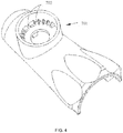
- FIG. 3 shows a bending control mechanism provided by the first embodiment of the invention, comprising wrench 1, central shaft 3, lifting ring 8, cam lock 9, upper part of rotating head 7 and compression spring 10; wherein an opening 701 provided with a series of locating grooves 702 is arranged on the upper part of rotating head 7;
- the central shaft 3 is provided with a gear 301, which is connected with the stapler jaw by connecting the rack 5 and further through the connecting device placed in the tubular structure;
- a lifting ring 8 in coaxial arrangement with the central shaft 3 contains drive ramp 802;
- a cam lock 9 in coaxial arrangement with the central shaft 3 contains a connecting boss 901 connected with the central shaft 3, a driven ramp 904 matched with the drive ramp 802 of the lifting ring 8, and a locating tooth 902;
- the wrench 1 is matched with the lifting ring 8 via the boss 105, and connected with the central shaft 3 via the pin 6;
- a compression spring 10 is arranged between the wrench 1 and the lifting ring 8.
- the angle range between the angle I and the angle III composes said angle range II.
- a plurality of engagement locked positions are arranged at the opening of the rotating head in the circumferential direction; along with rotation of the cam lock 9, the rotating head can be meshed to the corresponding engagement locked position by the cam lock 9.
- said surgical instrument is a surgical stapler; the linear power output mechanism D of said bending control mechanism is connected to the jaws of the stapler.
- the locating groove 702 on the rotating head has a middle position, so that the stapler jaw is in a straight line state.
- the pin hole 102 of the wrench 1 is matched with the fan-shaped hole 303 of the central shaft 3 via the pin 6; the angle of the fan-shaped hole 303 composes said relative rotating angle range; the wrench 1 extends downwards by means of a boss 105; the lifting ring 8 is provided with wrench fitting groove 801; and the boss 105 is engaged in the wrench fitting groove 801.
- said wrench 1 when the pin 6 is located at one end of the fan-shaped hole 303, said wrench 1 is at the angle I; when the pin 6 is located at the other end of the fan-shaped hole 303, said wrench 1 is at the angle III; when the pin 6 is located between one end and the other end of the fan-shaped hole 303, said wrench 1 is within the angle range II.
- the lifting ring 8 is provided with a drive ramp 802; the cam lock 9 is provided with a driven ramp 904, and the driven ramp 904 is matched in the drive ramp 802; when the lifting ring 8 driven by the wrench 1 rotates within the angle range II, there is a relative rotation between the lifting ring 8 and the cam lock 9; when the lifting ring 8 driven by the wrench 1 rotates to the angle I and angle III, the driven ramp 904 is driven by the drive ramp 802, so that the cam lock 9 is away from the rotating head, to separate from the engagement locking with the rotating head.
- the wrench 1 is provided with a cover plate 104; the cam lock 9 is provided with a compression spring support surface 903; a compression spring 10 is connected between the cover plate 104 and the compression spring support surface 903.
- a limit boss is arranged at the opening of the rotating head; and an angle limiting groove matched with the limit boss is arranged on said wrench 1.
- the locating grooves 702 on the rotating head are circumferentially arrayed; the angle distribution of each locating groove 702 is not equidistant.
- a limit boss is arranged at opening of the rotating head, to ensure that the wrench rotates in a certain angle, to prevent over-rotation.
- the angle distribution of the above-mentioned locking grooves can also be equal.
- the invention is a bending control mechanism of endoscopic stapler, comprising wrench 1, compression spring 10, cam lock 9, lifting ring 8, central shaft 3, upper part of rotating head 7, rack 5 and pin 6.
- the upper part of rotating head 7 has an opening, which can accommodate the wrench 1, compression spring 10, cam lock 9, lifting ring 8 and central shaft 3; the above-mentioned wrench 1, compression spring 10, cam lock 9, lifting ring 8 and central shaft 3 and opening of the rotating head are arranged coaxially; a series of locating grooves 702 are arranged in the opening.
- the central shaft 3, lifting ring 8 and cam lock 9 are arranged from inside to outside; the connecting boss 901 of the cam lock 9 is matched with the connecting groove 304 of the central shaft 3; the driven ramp 904 is matched with the drive ramp 802 of the lifting ring 8; the locating tooth 902 is arranged in a series of locating grooves 702 on the rotating head.
- the boss 105 of the wrench 1 is matched with the wrench fitting groove 801 of the lifting ring 8.
- the compression spring 10 is placed between the compression spring support surface 903 of the cam lock 9 and the cover plate 104 of the wrench 1.
- the pin hole 102 of the wrench 1 is matched with the fan-shaped hole 303 of the central shaft 3 via the pin 6.
- the rack 5 is arranged in the upper part of rotating head 7, and engaged with the gear 301 of the central shaft 3.
- the boss 105 of the wrench 1 drives the lifting ring 8 to rotate for an angle; the lifting ring 8 drives the driven ramp 904 of the cam lock 9 through the drive ramp 802, so that the cam lock 9 rises, and the locating tooth 902 and the locating groove 702 of the upper part of rotating head 7 disengage from the engaging state;
- the pin 6 drives the central shaft 3 to rotate through the fan-shaped hole 303, and the central shaft 3 drives the cam lock 9 to rotate and drives the rack 5 to move forward and backward, to play a role of turning.
- the wrench 1 When the wrench 1 rotates to the next position, the wrench 1 will be released; the compression spring 10 will push the cam lock 9, to clamp the locating tooth 902 into another locating groove 702 of the upper part of rotating head 7. At this time, the cam lock 9 can lock the central shaft 3, so that it cannot rotate freely. Since the locating tooth 902 of the cam lock 9 is engaged with the straight line segment of the locking groove 702 of the upper part of rotating head 7, the rotation of the gear 301 driven by the rack 5 cannot rotate the cam lock 9 to achieve the purpose of locking.
- a limit boss is arranged at opening of the upper part of rotating head, to limit the rotation angle of the wrench and avoid excessive rotation.
Landscapes
- Health & Medical Sciences (AREA)
- Surgery (AREA)
- Life Sciences & Earth Sciences (AREA)
- Heart & Thoracic Surgery (AREA)
- Engineering & Computer Science (AREA)
- Biomedical Technology (AREA)
- Nuclear Medicine, Radiotherapy & Molecular Imaging (AREA)
- Medical Informatics (AREA)
- Molecular Biology (AREA)
- Animal Behavior & Ethology (AREA)
- General Health & Medical Sciences (AREA)
- Public Health (AREA)
- Veterinary Medicine (AREA)
- Pathology (AREA)
- Oral & Maxillofacial Surgery (AREA)
- Surgical Instruments (AREA)
Applications Claiming Priority (2)
| Application Number | Priority Date | Filing Date | Title |
|---|---|---|---|
| CN201510026528.0A CN104546043B (zh) | 2015-01-19 | 2015-01-19 | 一种控弯机构及具有控弯机构的外科器械 |
| PCT/CN2015/090208 WO2016115918A1 (zh) | 2015-01-19 | 2015-09-22 | 一种控弯机构及具有控弯机构的外科器械 |
Publications (3)
| Publication Number | Publication Date |
|---|---|
| EP3222222A1 EP3222222A1 (en) | 2017-09-27 |
| EP3222222A4 EP3222222A4 (en) | 2018-01-17 |
| EP3222222B1 true EP3222222B1 (en) | 2019-03-13 |
Family
ID=53063870
Family Applications (1)
| Application Number | Title | Priority Date | Filing Date |
|---|---|---|---|
| EP15878587.3A Active EP3222222B1 (en) | 2015-01-19 | 2015-09-22 | Turning control mechanism and surgical instrument having turning control mechanism |
Country Status (6)
| Country | Link |
|---|---|
| US (1) | US10383632B2 (zh) |
| EP (1) | EP3222222B1 (zh) |
| JP (1) | JP6403903B2 (zh) |
| CN (1) | CN104546043B (zh) |
| BR (1) | BR112017013665B1 (zh) |
| WO (1) | WO2016115918A1 (zh) |
Families Citing this family (17)
| Publication number | Priority date | Publication date | Assignee | Title |
|---|---|---|---|---|
| CN104546043B (zh) * | 2015-01-19 | 2016-08-31 | 上海逸思医疗科技有限公司 | 一种控弯机构及具有控弯机构的外科器械 |
| CN104546048B (zh) * | 2015-01-19 | 2016-11-16 | 上海逸思医疗科技有限公司 | 一种外科器械及其控弯机构 |
| CN105596049B (zh) * | 2016-02-25 | 2017-12-26 | 常州市康迪医用吻合器有限公司 | 一种腔镜切割吻合器 |
| CN105962981B (zh) * | 2016-06-08 | 2018-10-02 | 宁波维尔凯迪医疗器械有限公司 | 一种关节转动结构及具有该结构的吻合器 |
| CN107411793A (zh) * | 2017-08-25 | 2017-12-01 | 上海逸思医疗科技有限公司 | 一种可重复使用的电动腔镜切割吻合器 |
| CN107693068B (zh) * | 2017-10-25 | 2020-09-08 | 宁波维尔凯迪医疗器械有限公司 | 一种角度变换机构及具有该结构的吻合器 |
| CN107714122B (zh) * | 2017-11-23 | 2023-08-25 | 常州市新能源吻合器总厂有限公司 | 一种具有旋转手柄的吻合器及其使用方法 |
| CN108938031B (zh) * | 2018-07-31 | 2023-08-04 | 江苏健瑞宝医疗科技股份有限公司 | 腔内切割吻合器的头部调整机构 |
| CN209695247U (zh) * | 2018-12-28 | 2019-11-29 | 南京畅丰生物科技有限公司 | 一种防转动活检针 |
| CN110897668A (zh) * | 2019-12-25 | 2020-03-24 | 江苏风和医疗器材股份有限公司 | 用于外科器械的端部执行器驱动装置及外科器械 |
| CN110960274B (zh) * | 2020-01-15 | 2024-05-17 | 江苏孜航精密五金有限公司 | 一种电动腔镜吻合器的吻切组件转向装置 |
| US11678904B2 (en) | 2020-07-15 | 2023-06-20 | Ezisurg Medical Co., Ltd. | Control end of surgical instrument and surgical instrument having the control end |
| CN112656471B (zh) * | 2020-12-21 | 2022-05-31 | 湖北瑞沃医药材料有限公司 | 一种腔镜切割吻合器的转向装置 |
| CN113303853B (zh) * | 2021-06-15 | 2022-12-23 | 常州安康医疗器械有限公司 | 一种腔镜下直线切割吻合器组件 |
| CN113317846B (zh) * | 2021-07-13 | 2022-12-02 | 上海长征医院 | 一种椎板切除减压用的吸引器枪状咬骨钳 |
| CN116269567B (zh) * | 2023-05-23 | 2023-09-12 | 杭州翡宠生物科学有限公司 | 缝线张紧装置 |
| CN117481724A (zh) * | 2023-06-30 | 2024-02-02 | 江苏风和医疗器材股份有限公司 | 外科器械 |
Family Cites Families (27)
| Publication number | Priority date | Publication date | Assignee | Title |
|---|---|---|---|---|
| US5713505A (en) * | 1996-05-13 | 1998-02-03 | Ethicon Endo-Surgery, Inc. | Articulation transmission mechanism for surgical instruments |
| US5704534A (en) * | 1994-12-19 | 1998-01-06 | Ethicon Endo-Surgery, Inc. | Articulation assembly for surgical instruments |
| US5823066A (en) * | 1996-05-13 | 1998-10-20 | Ethicon Endo-Surgery, Inc. | Articulation transmission mechanism for surgical instruments |
| US5865361A (en) * | 1997-09-23 | 1999-02-02 | United States Surgical Corporation | Surgical stapling apparatus |
| US7431188B1 (en) * | 2007-03-15 | 2008-10-07 | Tyco Healthcare Group Lp | Surgical stapling apparatus with powered articulation |
| US8061576B2 (en) * | 2007-08-31 | 2011-11-22 | Tyco Healthcare Group Lp | Surgical instrument |
| US7624902B2 (en) * | 2007-08-31 | 2009-12-01 | Tyco Healthcare Group Lp | Surgical stapling apparatus |
| US20090198272A1 (en) * | 2008-02-06 | 2009-08-06 | Lawrence Kerver | Method and apparatus for articulating the wrist of a laparoscopic grasping instrument |
| US8608045B2 (en) * | 2008-10-10 | 2013-12-17 | Ethicon Endo-Sugery, Inc. | Powered surgical cutting and stapling apparatus with manually retractable firing system |
| AT508161B1 (de) * | 2009-05-14 | 2011-08-15 | Peter Dr Metzger | Flexible chirurgische fasszange |
| US8132706B2 (en) * | 2009-06-05 | 2012-03-13 | Tyco Healthcare Group Lp | Surgical stapling apparatus having articulation mechanism |
| US9877720B2 (en) * | 2010-09-24 | 2018-01-30 | Ethicon Llc | Control features for articulating surgical device |
| CN102440813B (zh) * | 2010-09-30 | 2013-05-08 | 上海创亿医疗器械技术有限公司 | 带有链条关节的腔镜外科切割吻合器 |
| US8336754B2 (en) * | 2011-02-04 | 2012-12-25 | Covidien Lp | Locking articulation mechanism for surgical stapler |
| CN102525586B (zh) * | 2012-02-09 | 2016-02-24 | 上海逸思医疗科技有限公司 | 外科器械的控制装置 |
| US8979827B2 (en) * | 2012-03-14 | 2015-03-17 | Covidien Lp | Surgical instrument with articulation mechanism |
| US9179913B2 (en) * | 2012-03-16 | 2015-11-10 | Covidien Lp | Surgical fastening apparatus with directed overcrimp |
| CN202537596U (zh) * | 2012-04-16 | 2012-11-21 | 涂名超 | 可锁定钳头弯曲角度的腹腔镜手术钳 |
| CN102614006B (zh) * | 2012-04-16 | 2014-12-03 | 涂名超 | 可锁定钳头弯曲角度的腹腔镜手术钳 |
| US9186142B2 (en) * | 2013-02-28 | 2015-11-17 | Ethicon Endo-Surgery, Inc. | Surgical instrument end effector articulation drive with pinion and opposing racks |
| CN103263242B (zh) * | 2013-06-03 | 2015-09-23 | 深圳开立生物医疗科技股份有限公司 | 一种弯曲部控制机构及其内窥镜设备 |
| CN203970439U (zh) * | 2014-06-27 | 2014-12-03 | 瑞奇外科器械(中国)有限公司 | 外科手术器械的弯转装置及外科手术器械 |
| CN104207811A (zh) * | 2014-09-30 | 2014-12-17 | 山东威瑞外科医用制品有限公司 | 一次性腔内切割吻合器 |
| CN104546043B (zh) * | 2015-01-19 | 2016-08-31 | 上海逸思医疗科技有限公司 | 一种控弯机构及具有控弯机构的外科器械 |
| CN204445992U (zh) * | 2015-01-19 | 2015-07-08 | 上海逸思医疗科技有限公司 | 一种控弯机构及具有控弯机构的外科器械 |
| CN204445993U (zh) * | 2015-01-19 | 2015-07-08 | 上海逸思医疗科技有限公司 | 一种外科器械及其控弯机构 |
| CN104546048B (zh) * | 2015-01-19 | 2016-11-16 | 上海逸思医疗科技有限公司 | 一种外科器械及其控弯机构 |
-
2015
- 2015-01-19 CN CN201510026528.0A patent/CN104546043B/zh active Active
- 2015-09-22 JP JP2017548512A patent/JP6403903B2/ja active Active
- 2015-09-22 EP EP15878587.3A patent/EP3222222B1/en active Active
- 2015-09-22 BR BR112017013665-1A patent/BR112017013665B1/pt active IP Right Grant
- 2015-09-22 US US15/324,266 patent/US10383632B2/en active Active
- 2015-09-22 WO PCT/CN2015/090208 patent/WO2016115918A1/zh active Application Filing
Non-Patent Citations (1)
| Title |
|---|
| None * |
Also Published As
| Publication number | Publication date |
|---|---|
| US10383632B2 (en) | 2019-08-20 |
| CN104546043B (zh) | 2016-08-31 |
| BR112017013665B1 (pt) | 2022-05-10 |
| EP3222222A1 (en) | 2017-09-27 |
| JP2017536964A (ja) | 2017-12-14 |
| CN104546043A (zh) | 2015-04-29 |
| US20170196559A1 (en) | 2017-07-13 |
| BR112017013665A2 (pt) | 2018-03-13 |
| JP6403903B2 (ja) | 2018-10-10 |
| EP3222222A4 (en) | 2018-01-17 |
| WO2016115918A1 (zh) | 2016-07-28 |
Similar Documents
| Publication | Publication Date | Title |
|---|---|---|
| EP3222222B1 (en) | Turning control mechanism and surgical instrument having turning control mechanism | |
| EP3222221B1 (en) | Surgical instrument and turning control mechanism thereof | |
| US11096694B2 (en) | Firing assembly for circular stapler | |
| JP6066239B2 (ja) | マイクロカッタステープル留め器械クランプ及び配備機構体システム及び方法 | |
| CN103315788B (zh) | 适用于微创手术的切割吻合器 | |
| EP3395266B1 (en) | Hysteresis removal feature in surgical stapling instrument | |
| JP6946201B2 (ja) | 可逆モータを有する外科用ステープラー | |
| RU2677085C2 (ru) | Хирургический сшивающий инструмент с узлом привода, имеющим коленно-рычажные элементы | |
| WO2017063382A1 (zh) | 一种执行器可弯转的外科器械 | |
| KR20180134972A (ko) | 관절 메커니즘을 갖는 수술용 스테이플러 | |
| CN108112230A (zh) | 用于外科缝合器的应急组件 | |
| WO2020151334A1 (zh) | 外科手术器械和直线型吻合器 | |
| EP2958499A2 (en) | Surgical tool introducer | |
| US11596396B2 (en) | Surgical end effectors | |
| RU158519U1 (ru) | Устройство для наложения циркулярных анастомозов полых трубчатых органов |
Legal Events
| Date | Code | Title | Description |
|---|---|---|---|
| STAA | Information on the status of an ep patent application or granted ep patent |
Free format text: STATUS: THE INTERNATIONAL PUBLICATION HAS BEEN MADE |
|
| PUAI | Public reference made under article 153(3) epc to a published international application that has entered the european phase |
Free format text: ORIGINAL CODE: 0009012 |
|
| STAA | Information on the status of an ep patent application or granted ep patent |
Free format text: STATUS: REQUEST FOR EXAMINATION WAS MADE |
|
| 17P | Request for examination filed |
Effective date: 20170619 |
|
| AK | Designated contracting states |
Kind code of ref document: A1 Designated state(s): AL AT BE BG CH CY CZ DE DK EE ES FI FR GB GR HR HU IE IS IT LI LT LU LV MC MK MT NL NO PL PT RO RS SE SI SK SM TR |
|
| AX | Request for extension of the european patent |
Extension state: BA ME |
|
| A4 | Supplementary search report drawn up and despatched |
Effective date: 20171215 |
|
| RIC1 | Information provided on ipc code assigned before grant |
Ipc: A61B 17/072 20060101AFI20171211BHEP |
|
| DAV | Request for validation of the european patent (deleted) | ||
| DAX | Request for extension of the european patent (deleted) | ||
| RIN1 | Information on inventor provided before grant (corrected) |
Inventor name: LI, ANHUA Inventor name: SHI, XIUFENG Inventor name: YANG, GUANG Inventor name: ZHANG, XILIANG Inventor name: NIE, HONGLIN |
|
| GRAP | Despatch of communication of intention to grant a patent |
Free format text: ORIGINAL CODE: EPIDOSNIGR1 |
|
| STAA | Information on the status of an ep patent application or granted ep patent |
Free format text: STATUS: GRANT OF PATENT IS INTENDED |
|
| INTG | Intention to grant announced |
Effective date: 20181214 |
|
| GRAS | Grant fee paid |
Free format text: ORIGINAL CODE: EPIDOSNIGR3 |
|
| GRAA | (expected) grant |
Free format text: ORIGINAL CODE: 0009210 |
|
| STAA | Information on the status of an ep patent application or granted ep patent |
Free format text: STATUS: THE PATENT HAS BEEN GRANTED |
|
| AK | Designated contracting states |
Kind code of ref document: B1 Designated state(s): AL AT BE BG CH CY CZ DE DK EE ES FI FR GB GR HR HU IE IS IT LI LT LU LV MC MK MT NL NO PL PT RO RS SE SI SK SM TR |
|
| REG | Reference to a national code |
Ref country code: GB Ref legal event code: FG4D |
|
| REG | Reference to a national code |
Ref country code: CH Ref legal event code: EP Ref country code: AT Ref legal event code: REF Ref document number: 1106603 Country of ref document: AT Kind code of ref document: T Effective date: 20190315 |
|
| REG | Reference to a national code |
Ref country code: IE Ref legal event code: FG4D |
|
| REG | Reference to a national code |
Ref country code: DE Ref legal event code: R096 Ref document number: 602015026580 Country of ref document: DE |
|
| REG | Reference to a national code |
Ref country code: CH Ref legal event code: NV Representative=s name: VALIPAT S.A. C/O BOVARD SA NEUCHATEL, CH |
|
| REG | Reference to a national code |
Ref country code: SE Ref legal event code: TRGR |
|
| REG | Reference to a national code |
Ref country code: NL Ref legal event code: MP Effective date: 20190313 |
|
| REG | Reference to a national code |
Ref country code: LT Ref legal event code: MG4D |
|
| PG25 | Lapsed in a contracting state [announced via postgrant information from national office to epo] |
Ref country code: NO Free format text: LAPSE BECAUSE OF FAILURE TO SUBMIT A TRANSLATION OF THE DESCRIPTION OR TO PAY THE FEE WITHIN THE PRESCRIBED TIME-LIMIT Effective date: 20190613 Ref country code: LT Free format text: LAPSE BECAUSE OF FAILURE TO SUBMIT A TRANSLATION OF THE DESCRIPTION OR TO PAY THE FEE WITHIN THE PRESCRIBED TIME-LIMIT Effective date: 20190313 Ref country code: FI Free format text: LAPSE BECAUSE OF FAILURE TO SUBMIT A TRANSLATION OF THE DESCRIPTION OR TO PAY THE FEE WITHIN THE PRESCRIBED TIME-LIMIT Effective date: 20190313 |
|
| PG25 | Lapsed in a contracting state [announced via postgrant information from national office to epo] |
Ref country code: RS Free format text: LAPSE BECAUSE OF FAILURE TO SUBMIT A TRANSLATION OF THE DESCRIPTION OR TO PAY THE FEE WITHIN THE PRESCRIBED TIME-LIMIT Effective date: 20190313 Ref country code: HR Free format text: LAPSE BECAUSE OF FAILURE TO SUBMIT A TRANSLATION OF THE DESCRIPTION OR TO PAY THE FEE WITHIN THE PRESCRIBED TIME-LIMIT Effective date: 20190313 Ref country code: LV Free format text: LAPSE BECAUSE OF FAILURE TO SUBMIT A TRANSLATION OF THE DESCRIPTION OR TO PAY THE FEE WITHIN THE PRESCRIBED TIME-LIMIT Effective date: 20190313 Ref country code: NL Free format text: LAPSE BECAUSE OF FAILURE TO SUBMIT A TRANSLATION OF THE DESCRIPTION OR TO PAY THE FEE WITHIN THE PRESCRIBED TIME-LIMIT Effective date: 20190313 Ref country code: BG Free format text: LAPSE BECAUSE OF FAILURE TO SUBMIT A TRANSLATION OF THE DESCRIPTION OR TO PAY THE FEE WITHIN THE PRESCRIBED TIME-LIMIT Effective date: 20190613 Ref country code: GR Free format text: LAPSE BECAUSE OF FAILURE TO SUBMIT A TRANSLATION OF THE DESCRIPTION OR TO PAY THE FEE WITHIN THE PRESCRIBED TIME-LIMIT Effective date: 20190614 |
|
| REG | Reference to a national code |
Ref country code: AT Ref legal event code: MK05 Ref document number: 1106603 Country of ref document: AT Kind code of ref document: T Effective date: 20190313 |
|
| PG25 | Lapsed in a contracting state [announced via postgrant information from national office to epo] |
Ref country code: EE Free format text: LAPSE BECAUSE OF FAILURE TO SUBMIT A TRANSLATION OF THE DESCRIPTION OR TO PAY THE FEE WITHIN THE PRESCRIBED TIME-LIMIT Effective date: 20190313 Ref country code: PT Free format text: LAPSE BECAUSE OF FAILURE TO SUBMIT A TRANSLATION OF THE DESCRIPTION OR TO PAY THE FEE WITHIN THE PRESCRIBED TIME-LIMIT Effective date: 20190713 Ref country code: AL Free format text: LAPSE BECAUSE OF FAILURE TO SUBMIT A TRANSLATION OF THE DESCRIPTION OR TO PAY THE FEE WITHIN THE PRESCRIBED TIME-LIMIT Effective date: 20190313 Ref country code: SK Free format text: LAPSE BECAUSE OF FAILURE TO SUBMIT A TRANSLATION OF THE DESCRIPTION OR TO PAY THE FEE WITHIN THE PRESCRIBED TIME-LIMIT Effective date: 20190313 Ref country code: ES Free format text: LAPSE BECAUSE OF FAILURE TO SUBMIT A TRANSLATION OF THE DESCRIPTION OR TO PAY THE FEE WITHIN THE PRESCRIBED TIME-LIMIT Effective date: 20190313 Ref country code: CZ Free format text: LAPSE BECAUSE OF FAILURE TO SUBMIT A TRANSLATION OF THE DESCRIPTION OR TO PAY THE FEE WITHIN THE PRESCRIBED TIME-LIMIT Effective date: 20190313 Ref country code: RO Free format text: LAPSE BECAUSE OF FAILURE TO SUBMIT A TRANSLATION OF THE DESCRIPTION OR TO PAY THE FEE WITHIN THE PRESCRIBED TIME-LIMIT Effective date: 20190313 |
|
| PG25 | Lapsed in a contracting state [announced via postgrant information from national office to epo] |
Ref country code: SM Free format text: LAPSE BECAUSE OF FAILURE TO SUBMIT A TRANSLATION OF THE DESCRIPTION OR TO PAY THE FEE WITHIN THE PRESCRIBED TIME-LIMIT Effective date: 20190313 Ref country code: PL Free format text: LAPSE BECAUSE OF FAILURE TO SUBMIT A TRANSLATION OF THE DESCRIPTION OR TO PAY THE FEE WITHIN THE PRESCRIBED TIME-LIMIT Effective date: 20190313 |
|
| REG | Reference to a national code |
Ref country code: DE Ref legal event code: R097 Ref document number: 602015026580 Country of ref document: DE |
|
| PG25 | Lapsed in a contracting state [announced via postgrant information from national office to epo] |
Ref country code: AT Free format text: LAPSE BECAUSE OF FAILURE TO SUBMIT A TRANSLATION OF THE DESCRIPTION OR TO PAY THE FEE WITHIN THE PRESCRIBED TIME-LIMIT Effective date: 20190313 Ref country code: IS Free format text: LAPSE BECAUSE OF FAILURE TO SUBMIT A TRANSLATION OF THE DESCRIPTION OR TO PAY THE FEE WITHIN THE PRESCRIBED TIME-LIMIT Effective date: 20190713 |
|
| PLBE | No opposition filed within time limit |
Free format text: ORIGINAL CODE: 0009261 |
|
| STAA | Information on the status of an ep patent application or granted ep patent |
Free format text: STATUS: NO OPPOSITION FILED WITHIN TIME LIMIT |
|
| PG25 | Lapsed in a contracting state [announced via postgrant information from national office to epo] |
Ref country code: DK Free format text: LAPSE BECAUSE OF FAILURE TO SUBMIT A TRANSLATION OF THE DESCRIPTION OR TO PAY THE FEE WITHIN THE PRESCRIBED TIME-LIMIT Effective date: 20190313 |
|
| 26N | No opposition filed |
Effective date: 20191216 |
|
| PG25 | Lapsed in a contracting state [announced via postgrant information from national office to epo] |
Ref country code: SI Free format text: LAPSE BECAUSE OF FAILURE TO SUBMIT A TRANSLATION OF THE DESCRIPTION OR TO PAY THE FEE WITHIN THE PRESCRIBED TIME-LIMIT Effective date: 20190313 |
|
| PG25 | Lapsed in a contracting state [announced via postgrant information from national office to epo] |
Ref country code: TR Free format text: LAPSE BECAUSE OF FAILURE TO SUBMIT A TRANSLATION OF THE DESCRIPTION OR TO PAY THE FEE WITHIN THE PRESCRIBED TIME-LIMIT Effective date: 20190313 |
|
| PG25 | Lapsed in a contracting state [announced via postgrant information from national office to epo] |
Ref country code: MC Free format text: LAPSE BECAUSE OF FAILURE TO SUBMIT A TRANSLATION OF THE DESCRIPTION OR TO PAY THE FEE WITHIN THE PRESCRIBED TIME-LIMIT Effective date: 20190313 |
|
| PG25 | Lapsed in a contracting state [announced via postgrant information from national office to epo] |
Ref country code: IE Free format text: LAPSE BECAUSE OF NON-PAYMENT OF DUE FEES Effective date: 20190922 Ref country code: LU Free format text: LAPSE BECAUSE OF NON-PAYMENT OF DUE FEES Effective date: 20190922 |
|
| PG25 | Lapsed in a contracting state [announced via postgrant information from national office to epo] |
Ref country code: CY Free format text: LAPSE BECAUSE OF FAILURE TO SUBMIT A TRANSLATION OF THE DESCRIPTION OR TO PAY THE FEE WITHIN THE PRESCRIBED TIME-LIMIT Effective date: 20190313 |
|
| PG25 | Lapsed in a contracting state [announced via postgrant information from national office to epo] |
Ref country code: HU Free format text: LAPSE BECAUSE OF FAILURE TO SUBMIT A TRANSLATION OF THE DESCRIPTION OR TO PAY THE FEE WITHIN THE PRESCRIBED TIME-LIMIT; INVALID AB INITIO Effective date: 20150922 Ref country code: MT Free format text: LAPSE BECAUSE OF FAILURE TO SUBMIT A TRANSLATION OF THE DESCRIPTION OR TO PAY THE FEE WITHIN THE PRESCRIBED TIME-LIMIT Effective date: 20190313 |
|
| PG25 | Lapsed in a contracting state [announced via postgrant information from national office to epo] |
Ref country code: MK Free format text: LAPSE BECAUSE OF FAILURE TO SUBMIT A TRANSLATION OF THE DESCRIPTION OR TO PAY THE FEE WITHIN THE PRESCRIBED TIME-LIMIT Effective date: 20190313 |
|
| REG | Reference to a national code |
Ref country code: DE Ref legal event code: R082 Ref document number: 602015026580 Country of ref document: DE Representative=s name: SUN, YIMING, M.SC. DIPL. SC. POL. UNIV., DE |
|
| PGFP | Annual fee paid to national office [announced via postgrant information from national office to epo] |
Ref country code: GB Payment date: 20230920 Year of fee payment: 9 |
|
| PGFP | Annual fee paid to national office [announced via postgrant information from national office to epo] |
Ref country code: SE Payment date: 20230920 Year of fee payment: 9 Ref country code: FR Payment date: 20230928 Year of fee payment: 9 Ref country code: DE Payment date: 20230920 Year of fee payment: 9 Ref country code: BE Payment date: 20230920 Year of fee payment: 9 |
|
| PGFP | Annual fee paid to national office [announced via postgrant information from national office to epo] |
Ref country code: IT Payment date: 20230927 Year of fee payment: 9 Ref country code: CH Payment date: 20231001 Year of fee payment: 9 |