EP3221117B2 - Mehrfach-strangpresskopf - Google Patents
Mehrfach-strangpresskopf Download PDFInfo
- Publication number
- EP3221117B2 EP3221117B2 EP15797624.2A EP15797624A EP3221117B2 EP 3221117 B2 EP3221117 B2 EP 3221117B2 EP 15797624 A EP15797624 A EP 15797624A EP 3221117 B2 EP3221117 B2 EP 3221117B2
- Authority
- EP
- European Patent Office
- Prior art keywords
- flow channel
- head
- base body
- multiple extrusion
- extruder
- Prior art date
- Legal status (The legal status is an assumption and is not a legal conclusion. Google has not performed a legal analysis and makes no representation as to the accuracy of the status listed.)
- Active
Links
Images


Classifications
-
- B—PERFORMING OPERATIONS; TRANSPORTING
- B29—WORKING OF PLASTICS; WORKING OF SUBSTANCES IN A PLASTIC STATE IN GENERAL
- B29C—SHAPING OR JOINING OF PLASTICS; SHAPING OF MATERIAL IN A PLASTIC STATE, NOT OTHERWISE PROVIDED FOR; AFTER-TREATMENT OF THE SHAPED PRODUCTS, e.g. REPAIRING
- B29C48/00—Extrusion moulding, i.e. expressing the moulding material through a die or nozzle which imparts the desired form; Apparatus therefor
- B29C48/03—Extrusion moulding, i.e. expressing the moulding material through a die or nozzle which imparts the desired form; Apparatus therefor characterised by the shape of the extruded material at extrusion
- B29C48/07—Flat, e.g. panels
-
- B—PERFORMING OPERATIONS; TRANSPORTING
- B29—WORKING OF PLASTICS; WORKING OF SUBSTANCES IN A PLASTIC STATE IN GENERAL
- B29C—SHAPING OR JOINING OF PLASTICS; SHAPING OF MATERIAL IN A PLASTIC STATE, NOT OTHERWISE PROVIDED FOR; AFTER-TREATMENT OF THE SHAPED PRODUCTS, e.g. REPAIRING
- B29C48/00—Extrusion moulding, i.e. expressing the moulding material through a die or nozzle which imparts the desired form; Apparatus therefor
- B29C48/03—Extrusion moulding, i.e. expressing the moulding material through a die or nozzle which imparts the desired form; Apparatus therefor characterised by the shape of the extruded material at extrusion
- B29C48/12—Articles with an irregular circumference when viewed in cross-section, e.g. window profiles
-
- B—PERFORMING OPERATIONS; TRANSPORTING
- B29—WORKING OF PLASTICS; WORKING OF SUBSTANCES IN A PLASTIC STATE IN GENERAL
- B29C—SHAPING OR JOINING OF PLASTICS; SHAPING OF MATERIAL IN A PLASTIC STATE, NOT OTHERWISE PROVIDED FOR; AFTER-TREATMENT OF THE SHAPED PRODUCTS, e.g. REPAIRING
- B29C48/00—Extrusion moulding, i.e. expressing the moulding material through a die or nozzle which imparts the desired form; Apparatus therefor
- B29C48/16—Articles comprising two or more components, e.g. co-extruded layers
- B29C48/18—Articles comprising two or more components, e.g. co-extruded layers the components being layers
-
- B—PERFORMING OPERATIONS; TRANSPORTING
- B29—WORKING OF PLASTICS; WORKING OF SUBSTANCES IN A PLASTIC STATE IN GENERAL
- B29C—SHAPING OR JOINING OF PLASTICS; SHAPING OF MATERIAL IN A PLASTIC STATE, NOT OTHERWISE PROVIDED FOR; AFTER-TREATMENT OF THE SHAPED PRODUCTS, e.g. REPAIRING
- B29C48/00—Extrusion moulding, i.e. expressing the moulding material through a die or nozzle which imparts the desired form; Apparatus therefor
- B29C48/25—Component parts, details or accessories; Auxiliary operations
- B29C48/27—Cleaning; Purging; Avoiding contamination
- B29C48/271—Cleaning; Purging; Avoiding contamination of feeding units
-
- B—PERFORMING OPERATIONS; TRANSPORTING
- B29—WORKING OF PLASTICS; WORKING OF SUBSTANCES IN A PLASTIC STATE IN GENERAL
- B29C—SHAPING OR JOINING OF PLASTICS; SHAPING OF MATERIAL IN A PLASTIC STATE, NOT OTHERWISE PROVIDED FOR; AFTER-TREATMENT OF THE SHAPED PRODUCTS, e.g. REPAIRING
- B29C48/00—Extrusion moulding, i.e. expressing the moulding material through a die or nozzle which imparts the desired form; Apparatus therefor
- B29C48/25—Component parts, details or accessories; Auxiliary operations
- B29C48/30—Extrusion nozzles or dies
- B29C48/304—Extrusion nozzles or dies specially adapted for bringing together components, e.g. melts within the die
-
- B—PERFORMING OPERATIONS; TRANSPORTING
- B29—WORKING OF PLASTICS; WORKING OF SUBSTANCES IN A PLASTIC STATE IN GENERAL
- B29C—SHAPING OR JOINING OF PLASTICS; SHAPING OF MATERIAL IN A PLASTIC STATE, NOT OTHERWISE PROVIDED FOR; AFTER-TREATMENT OF THE SHAPED PRODUCTS, e.g. REPAIRING
- B29C48/00—Extrusion moulding, i.e. expressing the moulding material through a die or nozzle which imparts the desired form; Apparatus therefor
- B29C48/25—Component parts, details or accessories; Auxiliary operations
- B29C48/30—Extrusion nozzles or dies
- B29C48/32—Extrusion nozzles or dies with annular openings, e.g. for forming tubular articles
- B29C48/33—Extrusion nozzles or dies with annular openings, e.g. for forming tubular articles with parts rotatable relative to each other
-
- B—PERFORMING OPERATIONS; TRANSPORTING
- B29—WORKING OF PLASTICS; WORKING OF SUBSTANCES IN A PLASTIC STATE IN GENERAL
- B29C—SHAPING OR JOINING OF PLASTICS; SHAPING OF MATERIAL IN A PLASTIC STATE, NOT OTHERWISE PROVIDED FOR; AFTER-TREATMENT OF THE SHAPED PRODUCTS, e.g. REPAIRING
- B29C48/00—Extrusion moulding, i.e. expressing the moulding material through a die or nozzle which imparts the desired form; Apparatus therefor
- B29C48/25—Component parts, details or accessories; Auxiliary operations
- B29C48/30—Extrusion nozzles or dies
- B29C48/345—Extrusion nozzles comprising two or more adjacently arranged ports, for simultaneously extruding multiple strands, e.g. for pelletising
-
- B—PERFORMING OPERATIONS; TRANSPORTING
- B29—WORKING OF PLASTICS; WORKING OF SUBSTANCES IN A PLASTIC STATE IN GENERAL
- B29C—SHAPING OR JOINING OF PLASTICS; SHAPING OF MATERIAL IN A PLASTIC STATE, NOT OTHERWISE PROVIDED FOR; AFTER-TREATMENT OF THE SHAPED PRODUCTS, e.g. REPAIRING
- B29C48/00—Extrusion moulding, i.e. expressing the moulding material through a die or nozzle which imparts the desired form; Apparatus therefor
- B29C48/25—Component parts, details or accessories; Auxiliary operations
- B29C48/36—Means for plasticising or homogenising the moulding material or forcing it through the nozzle or die
- B29C48/49—Means for plasticising or homogenising the moulding material or forcing it through the nozzle or die using two or more extruders to feed one die or nozzle
-
- B—PERFORMING OPERATIONS; TRANSPORTING
- B29—WORKING OF PLASTICS; WORKING OF SUBSTANCES IN A PLASTIC STATE IN GENERAL
- B29D—PRODUCING PARTICULAR ARTICLES FROM PLASTICS OR FROM SUBSTANCES IN A PLASTIC STATE
- B29D30/00—Producing pneumatic or solid tyres or parts thereof
- B29D30/06—Pneumatic tyres or parts thereof (e.g. produced by casting, moulding, compression moulding, injection moulding, centrifugal casting)
- B29D30/52—Unvulcanised treads, e.g. on used tyres; Retreading
-
- B—PERFORMING OPERATIONS; TRANSPORTING
- B29—WORKING OF PLASTICS; WORKING OF SUBSTANCES IN A PLASTIC STATE IN GENERAL
- B29C—SHAPING OR JOINING OF PLASTICS; SHAPING OF MATERIAL IN A PLASTIC STATE, NOT OTHERWISE PROVIDED FOR; AFTER-TREATMENT OF THE SHAPED PRODUCTS, e.g. REPAIRING
- B29C48/00—Extrusion moulding, i.e. expressing the moulding material through a die or nozzle which imparts the desired form; Apparatus therefor
- B29C48/25—Component parts, details or accessories; Auxiliary operations
- B29C48/27—Cleaning; Purging; Avoiding contamination
- B29C48/272—Cleaning; Purging; Avoiding contamination of dies
-
- B—PERFORMING OPERATIONS; TRANSPORTING
- B29—WORKING OF PLASTICS; WORKING OF SUBSTANCES IN A PLASTIC STATE IN GENERAL
- B29C—SHAPING OR JOINING OF PLASTICS; SHAPING OF MATERIAL IN A PLASTIC STATE, NOT OTHERWISE PROVIDED FOR; AFTER-TREATMENT OF THE SHAPED PRODUCTS, e.g. REPAIRING
- B29C48/00—Extrusion moulding, i.e. expressing the moulding material through a die or nozzle which imparts the desired form; Apparatus therefor
- B29C48/25—Component parts, details or accessories; Auxiliary operations
- B29C48/30—Extrusion nozzles or dies
-
- B—PERFORMING OPERATIONS; TRANSPORTING
- B29—WORKING OF PLASTICS; WORKING OF SUBSTANCES IN A PLASTIC STATE IN GENERAL
- B29K—INDEXING SCHEME ASSOCIATED WITH SUBCLASSES B29B, B29C OR B29D, RELATING TO MOULDING MATERIALS OR TO MATERIALS FOR MOULDS, REINFORCEMENTS, FILLERS OR PREFORMED PARTS, e.g. INSERTS
- B29K2021/00—Use of unspecified rubbers as moulding material
- B29K2021/006—Thermosetting elastomers
-
- B—PERFORMING OPERATIONS; TRANSPORTING
- B29—WORKING OF PLASTICS; WORKING OF SUBSTANCES IN A PLASTIC STATE IN GENERAL
- B29K—INDEXING SCHEME ASSOCIATED WITH SUBCLASSES B29B, B29C OR B29D, RELATING TO MOULDING MATERIALS OR TO MATERIALS FOR MOULDS, REINFORCEMENTS, FILLERS OR PREFORMED PARTS, e.g. INSERTS
- B29K2027/00—Use of polyvinylhalogenides or derivatives thereof as moulding material
- B29K2027/06—PVC, i.e. polyvinylchloride
-
- B—PERFORMING OPERATIONS; TRANSPORTING
- B29—WORKING OF PLASTICS; WORKING OF SUBSTANCES IN A PLASTIC STATE IN GENERAL
- B29L—INDEXING SCHEME ASSOCIATED WITH SUBCLASS B29C, RELATING TO PARTICULAR ARTICLES
- B29L2030/00—Pneumatic or solid tyres or parts thereof
- B29L2030/002—Treads
Definitions
- the invention relates to a multiple extrusion head for producing tire treads, comprising (a) a base body having a first feed opening for connecting a first extruder, a second feed opening for connecting a second extruder, a third feed opening for connecting a third extruder, and a fourth feed opening for connecting a fourth extruder, (b) a first head part pivotably mounted relative to the base body and having a receptacle open in the direction of the base body, (c) a second head part pivotably mounted relative to the base body, (c) at least one flow channel insert pivotably mounted relative to the base body, (c) wherein the first head part and the second head part can be brought into a closed state in which the head parts are pressure-tightly connected to one another, and a first flow channel, a second flow channel, a third flow channel, and a fourth flow channel are formed in the multiple extrusion head, wherein each flow channel is connected to one, in particular exactly one, feed opening.
- Such a multiple extrusion head is known from the DE 197 57 261 C1 and is used to manufacture tire treads. These treads must meet different requirements at different locations, so they are made from more than one material, usually rubber. The material is fed to the extruder through the extrusion head. Similar multiple extrusion heads are disclosed in the publications DE 36 38 623 C1 , EP 2 308 666 A2 , EP 1 604 802 A2 and DE 35 06 257 C1 .
- a disadvantage of known multiple extrusion heads is that treads, which are required for the production of improved tires, cannot be produced.
- the invention is based on the object of improving the production of treads.
- the invention solves the problem by a generic multiple extrusion head in which the base body has a feed opening for connecting a fifth extruder and which has a second flow channel insert which is pivotally mounted relative to the base body independently of the first flow channel insert and delimits a fifth flow channel which is connected to the fifth feed opening.
- the advantage of such a multiple extrusion head is that more complex treads can be produced.
- the additional flow channel allows for the production of an additional region with different material properties than previously available tread profiles.
- Another advantage is that the multiple extrusion head is easy to clean, despite its expanded capability for producing more complex runner profiles. Feeding material for an additional flow channel is not straightforward, as it is necessary to ensure that the extrusion head can be cleaned. This is made possible by the pivoting ability of the second flow channel insert.
- the first head part is arranged above the second head part.
- the first head part is pivotably mounted about a transverse axis. This feature is understood, in particular, to mean that the head part is pivotably mounted about a pivot axis that forms an angle of no more than 15°, in particular no more than 2°, with the horizontal.
- the axis of rotation about which the first head part is pivotable runs as close as possible to a horizontal plane.
- the second head part is pivotably mounted about a second transverse axis, wherein the second transverse axis extends in the same direction as the first transverse axis.
- the first transverse axis and the second transverse axis form the smallest possible angle with one another, although minor deviations are possible.
- the angle between the first transverse axis and the second transverse axis is preferably less than 10°, in particular less than 2°.
- the first flow channel insert and the second flow channel insert have a common sealing surface. In other words, the first flow channel insert and the second flow channel bear against one another in such a way that they touch one another in a single surface.
- This surface is designed such that pressurized rubber present in the flow channels would creep along the sealing surface if the first flow channel insert and the second flow channel insert are not clamped towards one another.
- the advantage of this is that it results in a compact design and that the flow channel inserts are also easy to clean. If the flow channel inserts are swung out, they separate from each other along their sealing surface up to the screw tip and the flow channels formed by the flow channel inserts can be easily cleaned of the extrusion material that is injected into a profile by means of the extrusion head.
- the second flow channel insert preferably also has a sealing surface with the first head section.
- the advantages described above then also apply to the remaining flow channels.
- the multiple extrusion head it is possible for the multiple extrusion head to have a third flow channel insert that is pivotally mounted relative to the base body independently of the first flow channel insert and the second flow channel insert.
- the flow channel inserts are pivotally mounted relative to the base body about a common axis of rotation.
- the axis of rotation extends at an angle of no more than 15° to the horizontal.
- the flow channel inserts are configured such that, when the head portions are closed, the first flow channel insert and the second flow channel insert touch each other, forming a flow channel between them.
- This flow channel can be easily cleaned by selectively pivoting the individual flow channel inserts away.
- the multiple extrusion head preferably has an insert locking device by means of which the second flow channel insert can be fixed relative to the base body such that rubber present in the second flow channel and subjected to a pressure of 2.5 MPa can be held in the flow channel.
- the insert locking device is designed such that the first head part can be pivoted relative to the second flow channel insert when the second flow channel insert is fixed relative to the base body. It is then possible to pivot only the head part away and, for example, clean it without the first flow channel also having to be cleaned. With previous extrusion heads, it is always necessary to clean all flow channels when the extrusion head is opened. In particular, if the second flow channel has to be cleaned at shorter intervals, the insert locking device saves additional cleaning effort.
- the multiple extrusion head preferably also comprises a first head fixing device by means of which the first head part can be fixed relative to the base body, wherein the first head fixing device is designed such that the first head part can be pivoted relative to the base body when the second head part is fixed relative to the base body. If the second head part is fixed relative to the base body, this means in particular that rubber present in the first flow channel and in the second flow channel, which is under a pressure of 2.5 MPa, can be held in the flow channel. The rubber cannot therefore penetrate laterally into the sealing surfaces. If the first head part is arranged above the second head part, all flow channels can be cleaned at the top, while the lower ones do not necessarily have to be cleaned as well.
- the multiple extrusion head includes an actuating device for motorized pivoting of the second flow channel insert. This facilitates cleaning and also reduces the risk of accidents, since no additional tools are generally required to pivot the second flow channel insert away.
- the multiple extrusion head has a second head fixing device for motor-driven pivoting and fixing of the second head part relative to the base body.
- all flow channel inserts each have a drive that allows the flow channels to be automatically pivoted.
- Each of these drives is preferably designed to apply a locking force to the respective flow channel insert that is greater than the force exerted by the rubber in the flow channel under a pressure of 2.5 MPa. The rubber is then securely held in the flow channel. This avoids having to clean all flow channels when only one requires cleaning.
- the invention also solves the problem by a tread pattern manufacturing device having the features of claim 8.
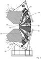
- Figure 1 shows a multiple extrusion head 10 according to the invention, which comprises a base body 12, a first head part 14, a second head part 16, a first flow channel insert 18 and a second flow channel insert 20.
- the base body 12 has a first feed opening 22, a second feed opening 24, a third feed opening 26, a fourth feed opening 28, and a fifth feed opening 30.
- material to be pressed for example, rubber
- material to be pressed is fed through all feed openings 22, 24, 26, 28, 30 by an extruder at a pressure p of at least 2.5 MPa.
- the ends of the extruder screws of the respective extruders, which extend into the feed openings 22, 24, 26, 28, 30, are shown schematically.
- the first head part 14 is pivotally mounted about a horizontal axis of rotation D 14 relative to the base body 12.
- the first head part 14 has a receptacle 32 which is open to the base body 12. This means that the first head part 14 forms a cavity with the base body 12 in the area of the receptacle 32 when the first head part 14 is in the Figure 3 shown closed position.
- the second flow channel insert 20 is arranged in this cavity.
- the second head part 16 is pivotally mounted about a rotation axis D 16 .
- the multiple extrusion head includes a first flow channel 34 extending from the first feed opening 22, a second flow channel 36 extending from the second feed opening 24, a third flow channel 38 extending from the third feed opening 26, a fourth flow channel 40 extending from the fourth feed opening 28, and a fifth flow channel 42 extending away from the fifth feed opening 30.
- Figure 2 shows that the second flow channel insert 20 delimits both the fourth flow channel 40 and the fifth flow channel 42.
- the first flow channel insert 18 and the second flow channel insert 20 touch each other and form the fourth flow channel 40 between them. It can also be seen that the first flow channel insert 18 delimits the third flow channel 38 and the fourth flow channel 40.
- the first flow channel insert 18 is pivotable by means of a drive 19 about the rotation axis D 14 , about which the first head part 14 is also pivotally mounted.
- Figure 2 is the first head fixing device 49 (see Figure 1 ) not shown.
- the multiple extrusion head 10 has an insert locking device 44, by means of which the second flow channel insert 20 can be pressed toward the base body 12.
- the insert locking device 44 comprises a hydraulic cylinder 46, whose piston rod 48 acts on the second flow channel insert 20 (see FIG. Fig. 1 ).
- the insert locking device 44 is designed such that it presses the second flow channel insert 20 so firmly against the base body 12 that material present in the flow channel, which is under a pressure of 2.5 MPa, in particular 3.5 MPa, cannot push the second flow channel insert 20 away from the base body 12.
- first head part 14 is pivotable relative to the second flow channel insert 20 by means of a first head fixing device 49, in particular even when the second flow channel insert 20 is fixed relative to the base body 12 by means of the insert locking device 44.
- Figure 1 also shows a second head fixing device 50, which in this case also comprises a hydraulic cylinder.
- the second head fixing device 50 acts on the second head part 16 so that it can be fixed relative to the base body 12.
- the first head part 14 can be pivoted relative to the base body 12 when the second head part 16 is fixed relative to the base body 12.
- the second head fixing device 50 is designed such that the material in the first flow channel 34 can be under a pressure of approximately 5 MPa, in particular 3.5 MPa, without this pressure being able to push the second head part 16 away from the base body 12.
- the second head part 16 can also be raised using the second head fixing device 50.
- the second head fixing device could therefore also be referred to as an actuating device.
- Figure 3 shows the multiple extrusion head 10 in the closed state. It is part of a tread profile manufacturing device according to the invention, which, in addition to the multiple extrusion head 10, has five extruders, each of which is connected to exactly one of the feed openings 22, 24, 26, 28, 30 for feeding extrusion material.
- Figure 4 shows the multiple extrusion head 10 with the second head section 16 open and a third flow channel insert 52, which is pivotable independently of the second head section 16 by means of a motor drive 54.
- the third flow channel insert 52 delimits the second flow channel 36 and the first flow channel 34.
- Figure 5 shows the multiple extrusion head with the first head section pivoted away and the second head section in the closed position.
- the flow channel inserts 18, 20, and 52 are attached to respective arms, which are pivotally mounted. This allows the flow channel inserts to be changed.
Landscapes
- Engineering & Computer Science (AREA)
- Mechanical Engineering (AREA)
- Manufacturing & Machinery (AREA)
- Extrusion Moulding Of Plastics Or The Like (AREA)
- Processing And Handling Of Plastics And Other Materials For Molding In General (AREA)
- Moulds For Moulding Plastics Or The Like (AREA)
Description
- Die Erfindung betrifft einen Mehrfach-Strangpresskopf zum Herstellen von Laufprofilen von Reifen, mit (a) einem Grundkörper, der eine erste Zuführöffnung zum Anschließen eines ersten Extruders, eine zweite Zuführöffnung zum Anschließen eines zweiten Extruders, eine dritte Zuführöffnung zum Anschließen eines dritten Extruders und eine vierte Zuführöffnung zum Anschließen eines vierten Extruders besitzt, (b) einem ersten Kopfteil, das relativ zum Grundkörper schwenkbar gelagert ist und eine in Richtung auf den Grundkörper offene Aufnahme aufweist, (c) einem zweiten Kopfteil, das relativ zum Grundkörper schwenkbar gelagert ist, (c) zumindest einem Fließkanaleinsatz, der relativ zum Grundkörper schwenkbar gelagert ist, (c) wobei das erste Kopfteil und das zweite Kopfteil in einen geschlossenen Zustand bringbar sind, in dem die Kopfteile miteinander druckfest verbunden sind und im Mehrfach-Strangpresskopf ein erster Fließkanal, ein zweiter Fließkanal, ein dritter Fließkanal und ein vierter Fließkanal gebildet sind, wobei jeder Fließkanal mit einer, insbesondere jeweils genau einer, Zuführöffnung verbunden ist.
- Ein derartiger Mehrfach-Strangpresskopf ist aus der
DE 197 57 261 C1 bekannt und wird zur Herstellung von Laufprofilen von Reifen verwendet. Diese Laufprofile müssen an unterschiedlichen Stellen verschiedene Anforderung erfüllen, so dass sie aus mehr als einem Material in der Regel Kautschuk oder Gummi, hergestellt werden. Das Material wird durch den Strangpresskopf dem Extruder zugeführt. Ähnliche Mehrfach-Strangpressköpfe offenbaren die DruckschriftenDE 36 38 623 C1 ,EP 2 308 666 A2 ,EP 1 604 802 A2 undDE 35 06 257 C1 . - Nachteilig an bekannten Mehrfach-Strangpressköpfen ist, dass Laufstreifen, die zur Fertigung von verbesserten Reifen benötigt werden, nicht hergestellt werden können.
- Der Erfindung liegt die Aufgabe zugrunde, die Fertigung von Laufstreifen zu verbessern.
- Die Erfindung löst das Problem durch einen gattungsgemäßen Mehrfach-Strangpresskopf, bei dem der Grundkörper eine Zuführöffnung zum Anschließen eines fünften Extruders hat und der einen zweiten Fließkanaleinsatz aufweist, der unabhängig vom ersten Fließkanaleinsatz relativ zum Grundkörper schwenkbar gelagert ist und einen fünften Fließkanal begrenzt, der mit der fünften Zuführöffnung verbunden ist.
- Vorteilhaft an einem derartigen Mehrfach-Strangpresskopf ist, dass komplexere Laufstreifen hergestellt werden können. Durch den zusätzlichen Fließkanal kann eine weitere Region hergestellt werden, die andere Materialeigenschaften besitzt als bisher herstellbare Laufprofile.
- Vorteilhaft ist zudem, dass der Mehrfach-Strangpresskopf trotz der erweiterten Möglichkeit zur Fertigung komplexerer Laufprofile einfach gereinigt werden kann. Das Zuführen von Material für einen weiteren Fließkanal ist nicht ohne Weiteres möglich, da sichergestellt werden muss, dass der Strangpresskopf gereinigt werden kann. Das wird durch die Schwenkbarkeit des zweiten Fließkanaleinsatzes ermöglicht.
- Es ist günstig, wenn das erste Kopfteil oberhalb des zweiten Kopfteils angeordnet ist. Insbesondere ist es vorteilhaft, wenn das erste Kopfteil um eine Querachse schwenkbar gelagert ist. Unter diesem Merkmal wird insbesondere verstanden, dass das Kopfteil um eine Schwenkachse schwenkbar gelagert ist, die mit der Horizontalen einen Winkel von höchstens 15°, insbesondere höchstens 2°, einnimmt. In aller Regel ist es vorteilhaft, wenn die Drehachse, um die das erste Kopfteil schwenkbar ist, in möglichst guter Näherung horizontal verläuft.
- Günstig ist es zudem, wenn das zweite Kopfteil um eine zweite Querachse schwenkbar gelagert ist, wobei sich die zweite Querachse in die gleiche Richtung wie die erste Querachse erstreckt. Hierunter ist insbesondere zu verstehen, dass es günstig ist, wenn die erste Querachse und die zweite Querachse einen möglichst geringen Winkel miteinander bilden, wobei kleinere Abweichungen möglich sind. Insbesondere ist der Winkel zwischen der ersten Querachse und der zweiten Querachse vorzugsweise kleiner als 10°, insbesondere kleiner als 2°. Gemäß einer bevorzugten Ausführungsform haben der erste Fließkanaleinsatz und der zweite Fließkanaleinsatz eine gemeinsame Dichtfläche. In anderen Worten liegen der erste Fließkanaleinsatz und der zweite Fließkanal so aneinander an, dass sie einander in einer Fläche berühren. Diese Fläche ist so ausgebildet, dass in den Fließkanälen vorhandenes, unter Druck stehendes Gummi die Dichtfläche entlang kriechen würde, wenn der erste Fließkanaleinsatz und der zweite Fließkanaleinsatz nicht aufeinander zu gespannt werden. Vorteilhaft hieran ist, dass sich eine kompakte Bauform ergibt und dass die Fließkanaleinsätze zudem leicht zu reinigen sind. Werden die Fließkanaleinsätze nämlich herausgeschwenkt, so trennen sie sich entlang ihrer Dichtfläche bis zur Schneckenspitze voneinander und die durch die Fließkanaleinsätze gebildeten Fließkanäle können einfach von dem Strangpressmaterial, das mittels des Strangpresskopfs zu einem Profil gespritzt wird, gereinigt werden.
- Wenn neben dem ersten und dem zweiten Fließkanaleinsatz kein weiterer Fließkanaleinsatz vorhanden ist, hat der zweite Fließkanaleinsatz vorzugsweise auch eine Dichtfläche mit dem ersten Kopfteil. Es ergeben sich dann die oben geschilderten Vorteile auch für die übrigen Fließkanäle. Es ist jedoch möglich, dass der Mehrfach-Strangpresskopf einen dritten Fließkanaleinsatz aufweist, der unabhängig vom ersten Fließkanaleinsatz und vom zweiten Fließkanaleinsatz relativ zum Grundkörper schwenkbar gelagert ist.
- Erfindungsgemäß sind die Fließkanaleinsätze um eine gemeinsame Drehachse relativ zum Grundkörper schwenkbar gelagert. Vorzugsweise verläuft die Drehachse unter einem Winkel von höchstens 15° zur Horizontalen.
- Vorteilhaft an einer gemeinsamen Schwenkachse ist, dass der Strangpresskopf besonders prozesssicher zu bedienen ist. Es wird zudem mit einfachen Mitteln eine hohe Dichtigkeit hergestellt und die Fertigung wird erleichtert.
- Vorzugsweise sind die Fließkanaleinsätze so ausgebildet, dass dann, wenn die Kopfteile im geschlossenen Zustand sind, der erste Fließkanaleinsatz und der zweite Fließkanaleinsatz einander berühren und zwischen einander einen Fließkanal bilden. Dieser kann durch selektives Wegschwenken der einzelnen Fließkanaleinsätze leicht gereinigt werden.
- Vorzugsweise weist der Mehrfach-Strangpresskopf eine Einsatz-Zuhaltevorrichtung auf, mittels der der zweite Fließkanaleinsatz so relativ zum Grundkörper fixierbar ist, dass im zweiten Fließkanal vorhandenes, unter einem Druck von 2,5 MPa stehendes Gummi im Fließkanal haltbar ist, wobei die Einsatz-Zuhaltevorrichtung so ausgebildet ist, dass das erste Kopfteil relativ zum zweiten Fließkanaleinsatz schwenkbar ist, wenn der zweite Fließkanaleinsatz relativ zum Grundkörper fixiert ist. Es ist dann möglich, nur das Kopfteil wegzuschwenken und beispielsweise zu reinigen, ohne dass der erste Fließkanal auch gereinigt werden müsste. Bei bisherigen Strangpressköpfen ist es stets notwendig, alle Fließkanäle zu reinigen, wenn der Strangpresskopf geöffnet wird. Insbesondere dann, wenn der zweite Fließkanal in kürzeren Intervallen gereinigt werden muss, erspart die Einsatz-Zuhaltevorrichtung zusätzlichen Reinigungsaufwand.
- Vorzugsweise umfasst der Mehrfach-Strangpresskopf zudem eine Erstkopf-Fixiervorrichtung, mittels der das erste Kopfteil relativ zum Grundkörper fixierbar sind, wobei die Erstkopf-Fixiervorrichtung so ausgebildet ist, dass das erste Kopfteil relativ zum Grundkörper verschwenkbar ist, wenn das zweite Kopfteil relativ zum Grundkörper fixiert ist. Wenn das zweite Kopfteil relativ zum Grundkörper fixiert ist, bedeutet das insbesondere, dass im ersten Fließkanal und im zweiten Fließkanal vorhandenes, unter einem Druck von 2,5 MPa stehendes Gummi im Fließkanal haltbar ist. Das Gummi kann also nicht seitlich in die Dichtflächen eindringen. Wenn das erste Kopftell oberhalb des zweiten Kopfteils angeordnet ist, können so alle Fließkanäle oben gereinigt werden, während die unteren nicht zwangsläufig auch gereinigt werden müssen.
- Gemäß einer bevorzugten Ausführungsform umfasst der Mehrfach-Strangpresskopf eine Kopf-Fixiervorrichtung, mittels der die Kopfteile und alle Fließkanaleinsätze relativ zum Grundkörper fixierbar sind. Die Kopf-Fixiervorrichtung ist insbesondere so ausgebildet, dass der beim Extrudieren herrschende Innendruck aufgefangen wird. Diese Kopf-Fixiervorrichtung ist vorzugsweise unabhängig von der Einsatz-Zuhaltevorrichtung und/oder der Zweitkopft-Fixiervorrichtung. Das hat den Vorteil, dass die etwaig vorhandenen sonstigen Fixiervorrichtungen für eine geringere Kraft ausgelegt werden können, was die Konstruktion vereinfacht. Beispielsweise ist die Kopf-Fixiereinrichtung ausgebildet zum formschlüssigen Fixieren der Kopfteile.
- Vorzugsweise umfasst der Mehrfach-Strangpresskopf eine Betätigungsvorrichtung zum motorischen Schwenken des zweiten Fließkanaleinsatzes. Das erleichtert die Reinigung und vermindert zudem die Unfallgefahr, da in der Regel kein zusätzliches Werkzeug notewendig ist, um den zweiten Fließkanaleinsatz wegzuschwenken.
- Vorzugsweise besitzt der Mehrfach-Strangpresskopf eine Zweitkopf-Fixiervorrichtung zum motorischen Schwenken und Fixieren des zweiten Kopfteils relativ zum Grundkörper.
- Besonders günstig ist es, wenn alle Fließkanaleinsätze jeweils einen Antrieb besitzen, mittels dem die Fließkanäle automatisch verschwenkbar sind. Jeder dieser Antriebe ist vorzugsweise ausgebildet zum Aufbringen einer Zuhaltekraft auf den jeweiligen Fließkanaleinsatz, die so größer ist als die Kraft, die von im Fließkanal unter einem Druck von 2,5 MPa stehenden Gummi ausgeübt wird. Das Gummi wird dann sicher im Fließkanal gehalten. Es wird so vermieden, dass alle Fließkanal gereinigt werden müssen, obwohl nur ein Fließkanal der Reinigung bedarf.
- Die Erfindung löst das Problem zudem durch eine Laufprofil-Herstellvorrichtung mit den Merkmalen von Anspruch 8.
- Im Folgenden wird die Erfindung anhand der beigefügten Zeichnungen näher erläutert. Dabei zeigt
- Figur 1
- einen Querschnitt durch einen erfindungsgemäßen Mehrfach-Strangpresskopf, bei dem ein Kopfteil und ein Fließkanaleinsatz weggeschwenkt sind,
- Figur 2
- den Mehrfach-Strangpresskopf gemäß
Figur 1 , bei dem lediglich das erste Kopfteil weggeschwenkt ist, und - Figur 3
- den Mehrfach-Strangpresskopf im geschlossenen Zustand.
- Figur 4
- zeigt den Mehrfach-Strangpresskopf, bei dem lediglich der zweite Fließkanal geschlossen ist und
- Figur 5
- zeigt den Mehrfach-Strangpresskopf nach
Figur 4 , bei dem das erste Kopfteil weggeschwenkt ist und das zweite Kopfteil in der geschlossenen Stellung ist. -
Figur 1 zeigt einen erfindungsgemäßen Mehrfach-Strangpresskopf 10, der einen Grundkörper 12, ein erstes Kopfteil 14, ein zweites Kopfteil 16, einen ersten Fließkanaleinsatz 18 und einen zweiten Fließkanaleinsatz 20 umfasst. - Der Grundkörper 12 besitzt eine erste Zuführöffnung 22, eine zweite Zuführöffnung 24, eine dritte Zuführöffnung 26, eine vierte Zuführöffnung 28 und eine fünfte Zuführöffnung 30. Durch alle Zuführöffnungen 22, 24, 26, 28, 30 wird im Betrieb des Mehrfach-Strangpresskopfs 10 zu verpressendes Material, beispielsweise Gummi oder Kautschuk, unter einem Druck p von zumindest 2,5 MPa von jeweils einem Extruder zugeführt. Schematisch sind von den jeweiligen Extrudern die Enden der Extruderschnecken gezeigt, die in die Zuführöffnungen 22, 24, 26, 28, 30 ragen.
- Das erste Kopfteil 14 ist um eine horizontale Drehachse D14 relativ zum Grundkörper 12 schwenkbar gelagert. Das erste Kopfteil 14 besitzt eine Aufnahme 32, die zum Grundkörper 12 offen ist. Hierunter ist zu verstehen, dass das erste Kopfteil 14 in dem Bereich der Aufnahme 32 einen Hohlraum mit dem Grundkörper 12 bildet, wenn das erste Kopfteil 14 in der in
Figur 3 gezeigten geschlossenen Stellung ist. In diesem Hohlraum ist insbesondere der zweite Fließkanaleinsatz 20 angeordnet. Das zweite Kopfteil 16 ist um eine Drehachse D16 schwenkbar gelagert. - Der Mehrfach-Strangpresskopf umfasst einen ersten Fließkanal 34, der sich von der ersten Zuführöffnung 22 aus erstreckt, einen zweiten Fließkanal 36, der sich von der zweiten Zuführöffnung 24 aus erstreckt, einen dritten Fließkanal 38, der sich von der dritten Zuführöffnung 26 aus erstreckt, einen vierten Fließkanal 40, der sich von der vierten Zuführöffnung 28 aus erstreckt und einen fünften Fließkanal 42, der sich von der fünften Zuführöffnung 30 weg erstreckt.
-
Figur 2 zeigt, dass der zweite Fließkanaleinsatz 20 sowohl den vierten Fließkanal 40 als auch den fünften Fließkanal 42 begrenzt. Der erste Fließkanaleinsatz 18 und der zweite Fließkanaleinsatz 20 berühren einander und bilden zwischen einander den vierten Fließkanal 40. Es ist zudem zu erkennen, dass der erste Fließkanaleinsatz 18 den dritten Fließkanal 38 und den vierten Fließkanal 40 begrenzt. Der erste Fließkanaleinsatz 18 ist mittels eines Antriebs 19 um die Drehachse D14 schwenkbar, um die auch das erste Kopfteil 14 schwenkbar gelagert ist. InFigur 2 ist die Erstkopf-Fixiervorrichtung 49 (sieheFigur 1 ) nicht eingezeichnet. - Der Mehrfach-Strangpresskopf 10 besitzt eine Einsatz-Zuhaltevorrichtung 44, mittels der der zweite Fließkanaleinsatz 20 auf den Grundkörper 12 zu drückbar ist. Im vorliegenden Fall umfasst die Einsatz-Zuhaltevorrichtung 44 einen Hydraulikzylinder 46, dessen Kolbenstange 48 auf den zweiten Fließkanaleinsatz 20 wirkt (vgl.
Fig. 1 ). Die Einsatz-Zuhaltevorrichtung 44 ist so ausgebildet, dass sie den zweiten Fließkanaleinsatz 20 so fest gegen den Grundkörper 12 presst, dass im Fließkanal vorhandenes Material, das unter einem Druck von 2,5 MPa, insbesondere von 3,5 MPa, steht, den zweiten Fließkanaleinsatz 20 nicht vom Grundkörper 12 wegdrücken kann. - Es ist zu erkennen, dass das erste Kopfteil 14 mittels einer Erstkopf-Fixiervorrichtung 49 relativ zum zweiten Fließkanaleinsatz 20 schwenkbar ist, insbesondere auch dann, wenn der zweite Fließkanaleinsatz 20 mittels der Einsatz-Zuhaltevorrichtung 44 relativ zum Grundkörper 12 fixiert ist.
-
Figur 1 zeigt zudem eine Zweitkopf-Fixiervorrichtung 50, die im vorliegenden Fall ebenfalls einen Hydraulikzylinder umfasst. Die Zweitkopf-Fixiervorrichtung 50 wirkt auf das zweite Kopfteil 16, so dass dieses relativ zum Grundkörper 12 fixierbar ist. Wie inFigur 1 gezeigt ist, kann das erste Kopfteil 14 relativ zum Grundkörper 12 verschwenkt werden, wenn das zweite Kopfteil 16 relativ zum Grundkörper 12 fixiert ist. Die Zweitkopf-Fixiervorrichtung 50 ist so ausgelegt, dass das Material im ersten Fließkanal 34 unter einem Druck von cirka 5 MPa, insbesondere 3,5 Mpa, stehen kann, ohne dass dieser Druck das zweite Kopfteil 16 vom Grundkörper 12 wegdrücken kann. - Mittels der Zweitkopf-Fixiervorrichtung 50 kann das zweite Kopfteil 16 zudem aufgefahren werden. Die Zweitkopf-Fixiervorrichtung könnte damit auch als Betätigungsvorrichtung bezeichnet werden.
-
Figur 3 zeigt den Mehrfach-Strangpresskopf 10 im geschlossenen Zustand. Er ist Teil einer erfindungsgemäßen Laufprofil-Herstellvorrichtung, die neben dem Mehrfach-Strangpresskopf 10 fünf Extruder aufweist, von denen jeweils einer mit genau einer der Zuführöffnungen 22, 24, 26, 28, 30 zum Zuführen von Extrusionsmaterial verbunden ist. -
Figur 4 zeigt den Mehrfach-Strangpresskopf 10 mit geöffnetem zweitem Kopfteil 16 und einem dritten Fließkanaleinsatz 52, der unabhängig vom zweiten Kopfteil 16 motorisch mittels eines Antriebs 54 schwenkbar ist. Der dritte Fließkanaleinsatz 52 begrenzt den zweiten Fließkanal 36 und den ersten Fließkanal 34. -
Figur 5 zeigt den Mehrfach-Strangpresskopf, bei dem das erste Kopfteil weggeschwenkt ist und das zweite Kopfteil in der geschlossenen Stellung ist. - Die Fließkanaleinsätze 18, 20 und 52 sind, was eine bevorzugte Ausführungsform darstellt, an jeweiligen Armen befestigt, wobei die Arme schwenkbar gelagert sind. Das ermöglicht es, die Fließkanaleinsätze zu wechseln.
-
- 10
- Mehrfach-Strangpresskopf
- 12
- Grundkörper
- 14
- Erstes Kopfteil
- 16
- Zweites Kopfteil
- 18
- Erster Fließkanaleinsatz
- 20
- Zweiter Fließkanaleinsatz
- 22
- Erste Zuführöffnung
- 24
- Zweite Zuführöffnung
- 26
- Dritte Zuführöffnung
- 28
- Vierte Zuführöffnung
- 30
- Fünfte Zuführöffnung
- 32
- Aufnahme
- 34
- Erster Fließkanal
- 36
- Zweiter Fließkanal
- 38
- Dritter Fließkanal
- 40
- Vierter Fließkanal
- 42
- Fünfter Fließkanal
- 44
- Einsatz-Zuhaltevorrichtung
- 46
- Hydraulikzylinder
- 48
- Kolbenstange
- 49
- Erstkopf-Fixiervorrichtung
- 50
- Zweitkopf-Fixiervorrichtung
- 52
- Dritter Fließkanaleinsatz
- 54
- Antrieb
- P
- Druck
- D14,16
- Drehachse
Claims (8)
- Mehrfach-Strangpresskopf zum Herstellen von Laufprofilen von Reifen, mit(a) einem Grundkörper (12), der- eine erste Zuführöffnung (22) zum Anschließen eines ersten Extruders,- eine zweite Zuführöffnung (24) zum Anschließen eines zweiten Extruders,- eine dritte Zuführöffnung (26) zum Anschließen eines dritten Extruders und- eine vierte Zuführöffnung (28) zum Anschließen eines vierten Extruders besitzt,(b) einem ersten Kopfteil (14), dasrelativ zum Grundkörper (12) schwenkbar gelagert ist undeine in Richtung auf den Grundkörper (12) offene Aufnahme (32) aufweist,(c) einem zweiten Kopfteil (16), das
relativ zum Grundkörper (12) schwenkbar gelagert ist,(d) zumindest einem Fließkanaleinsatz (18, 20), der
relativ zum Grundkörper (12) schwenkbar gelagert ist,(e) wobei das erste Kopfteil (14) und das zweite Kopfteil (16) in einen geschlossenen Zustand bringbar sind, in dem- die Kopfteile (14,16) miteinander druckfest verbunden sind und- im Mehrfach-Strangpresskopf (10) ein erster Fließkanal (34), ein zweiter Fließkanal (36), ein dritter Fließkanal (38) und ein vierter Fließkanal (40) gebildet sind, wobei jeder Fließkanal mit einer Zuführöffnung verbunden ist,dadurch gekennzeichnet, dass(f) der Grundkörper (12) eine fünfte Zuführöffnung (30) zum Anschließen eines fünften Extruders hat und dass(g) der Mehrfach-Strangpresskopf (10) einen zweiten Fließkanaleinsatz (20) aufweist, wobei die Fließkanaleinsätze (18, 20) um eine gemeinsame Drehachse (D14) relativ zum Grundkörper (12) schwenkbar gelagert sind, wobei
der zweite Fließkanaleinsatz (20)- unabhängig vom ersten Fließkanaleinsatz (18) relativ zum Grundkörper um die gemeinsame Drehachse (D14) schwenkbar gelagert ist und- einen fünften Fließkanal (42) begrenzt, der mit der fünften Zuführöffnung (30) verbunden ist. - Mehrfach-Strangpresskopf nach Anspruch 1, dadurch gekennzeichnet, dass der erste Fließkanaleinsatz (18) und der zweite Fließkanaleinsatz (20) eine gemeinsame Dichtfläche haben.
- Mehrfach-Strangpresskopf nach einem der vorstehenden Ansprüche, dadurch gekennzeichnet, dass wenn die Kopfteile (14,16) im geschlossenen Zustand sind, der erste Fließkanaleinsatz (18) und der zweite Fließkanaleinsatz (20) einander berühren und zwischen einander den vierten Fließkanal (40) bilden.
- Mehrfach-Strangpresskopf nach einem der vorstehenden Ansprüche,
gekennzeichnet durch
eine Erstkopf-Fixiervorrichtung (49),mittels der das erste Kopfteil (14) relativ zum Grundkörper (12) bewegbar und fixierbar ist,wobei die Erstkopf-Fixiervorrichtung so ausgebildet ist, dass das erste Kopfteil (14) relativ zum Grundkörper (12) verschwenkbar ist, wenn das zweite Kopfteil (16) relativ zum Grundkörper (12) fixiert ist. - Mehrfach-Strangpresskopf nach einem der vorstehenden Ansprüche,
gekennzeichnet durch eine Kopf-Fixiervorrichtung, mittels der die Kopfteile (14,16) und alle Fließkanaleinsätze (18, 20) relativ zum Grundkörper (12) fixierbar sind. - Mehrfach-Strangpresskopf nach einem der vorstehenden Ansprüche,
gekennzeichnet durch eine Betätigungsvorrichtung zum motorischen Schwenken des zweiten Fließkanaleinsatzes (20) relativ zum ersten Fließkanaleinsatz (18). - Mehrfach-Strangpresskopf nach einem der vorstehenden Ansprüche,
gekennzeichnet durch eine Zweitkopf-Fixiervorrichtung (50) zum motorischen Schwenken und Fixieren des zweiten Kopfteils (16) relativ zum Grundkörper (12). - Laufprofil-Herstellvorrichtung zum Herstellen von Laufprofilen von Fahrzeugreifen, mit- einem Mehrfach-Strangpresskopf (10) nach einem der vorstehenden Ansprüche,- einem ersten Extruder, der an die erste Zuführöffnung (22) angeschlossen ist,- einem zweiten Extruder, der an die zweite Zuführöffnung (24) angeschlossen ist, einem dritten Extruder, der an die dritte Zuführöffnung (26) angeschlossen ist, einem vierten Extruder, der an die vierte Zuführöffnung (28) angeschlossen ist, und- zumindest einem fünften Extruder, der an die zumindest eine fünfte Zuführöffnung (30) angeschlossen ist.
Applications Claiming Priority (2)
| Application Number | Priority Date | Filing Date | Title |
|---|---|---|---|
| DE102014117068.7A DE102014117068B4 (de) | 2014-11-21 | 2014-11-21 | Mehrfach-Strangpresskopf sowie Laufprofil-Herstellvorrichtung zum Herstellen von Laufprofilen von Fahrzeugreifen |
| PCT/EP2015/076070 WO2016078951A1 (de) | 2014-11-21 | 2015-11-09 | Mehrfach-strangpresskopf |
Publications (3)
| Publication Number | Publication Date |
|---|---|
| EP3221117A1 EP3221117A1 (de) | 2017-09-27 |
| EP3221117B1 EP3221117B1 (de) | 2019-04-17 |
| EP3221117B2 true EP3221117B2 (de) | 2025-04-30 |
Family
ID=54608497
Family Applications (1)
| Application Number | Title | Priority Date | Filing Date |
|---|---|---|---|
| EP15797624.2A Active EP3221117B2 (de) | 2014-11-21 | 2015-11-09 | Mehrfach-strangpresskopf |
Country Status (14)
| Country | Link |
|---|---|
| US (1) | US10513072B2 (de) |
| EP (1) | EP3221117B2 (de) |
| JP (1) | JP6714590B2 (de) |
| KR (1) | KR102312823B1 (de) |
| CN (1) | CN107073785B (de) |
| BR (1) | BR112017007223B1 (de) |
| CA (1) | CA2966379C (de) |
| DE (1) | DE102014117068B4 (de) |
| HU (1) | HUE043707T2 (de) |
| MX (1) | MX378065B (de) |
| PT (1) | PT3221117T (de) |
| RU (1) | RU2697462C2 (de) |
| TR (1) | TR201906770T4 (de) |
| WO (1) | WO2016078951A1 (de) |
Families Citing this family (6)
| Publication number | Priority date | Publication date | Assignee | Title |
|---|---|---|---|---|
| EP3645236B1 (de) * | 2017-06-30 | 2021-04-07 | Compagnie Générale des Etablissements Michelin | Extrusionskopf mit kanälen zur herstellung von einsätzen in einem profilband zur herstellung eines luftreifens und entsprechendes extrusionsverfahren |
| US11697237B2 (en) | 2018-12-19 | 2023-07-11 | The Goodyear Tire & Rubber Company | Dual compound extruder apparatus with rotatable head |
| US11505001B2 (en) * | 2018-12-19 | 2022-11-22 | The Goodyear Tire & Rubber Company | Method for forming tire components |
| JP6518390B1 (ja) * | 2019-01-11 | 2019-05-22 | 中田エンヂニアリング株式会社 | 多層押出し装置のヘッド |
| DE102019211020A1 (de) | 2019-07-25 | 2021-01-28 | Continental Reifen Deutschland Gmbh | Formgebungsvorrichtung zum Leiten von extrudierten Kautschukmischungen in eine Endformeinheit zum Ausformen von Kautschukmischungen, Verwendung der Vorrichtung und ein Verfahren zum Ausformen eines Kautschukprofils |
| CN110432723A (zh) * | 2019-07-30 | 2019-11-12 | 三明学院 | 一种聋哑人闹钟枕头 |
Citations (56)
| Publication number | Priority date | Publication date | Assignee | Title |
|---|---|---|---|---|
| CH509147A (fr) † | 1968-05-29 | 1971-06-30 | Uniroyal Englebert Ag | Filière d'extrusion |
| JPS5458762A (en) † | 1977-10-19 | 1979-05-11 | Sumitomo Rubber Ind | Metal mold for multiple extrusion of thermoplastic material |
| JPS57210839A (en) † | 1981-06-22 | 1982-12-24 | Toyo Tire & Rubber Co Ltd | Extrusion-head for rubber extruder |
| DE8421868U1 (de) † | 1984-07-21 | 1985-01-10 | Paul Troester Maschinenfabrik, 3000 Hannover | Strangpresskopf |
| US4515738A (en) † | 1983-04-27 | 1985-05-07 | Hermann Berstorff Maschinenbau Gmbh | Method of monitoring the production of extruded profiles and an apparatus incorporating means for effecting such monitoring |
| US4548568A (en) † | 1982-10-15 | 1985-10-22 | Hermann Berstorff Maschinenbau Gmbh | Extrusion head |
| EP0165412A1 (de) † | 1984-05-19 | 1985-12-27 | Continental Aktiengesellschaft | Aufklappbarer Presskopf für Strangpressen |
| DE3430062A1 (de) † | 1984-08-16 | 1986-02-27 | Fried. Krupp Gmbh, 4300 Essen | Mehrteilige spritzkopfanlage fuer extrudierbare plastische werkstoffe |
| EP0201337A2 (de) † | 1985-05-08 | 1986-11-12 | The Uniroyal Goodrich Tire Company | Extrusionssystem mit frühzeitiger progressiver Strangvereinigung |
| US4652224A (en) † | 1984-07-21 | 1987-03-24 | Paul Torester Maschinenfabrik | Extrusion head |
| US4693855A (en) † | 1985-09-30 | 1987-09-15 | Hermann Berstorff Maschinenbau Gmbh | Method for reducing wastage in a multiple-head extrusion device |
| EP0270816A1 (de) † | 1986-11-27 | 1988-06-15 | Fried. Krupp Gesellschaft mit beschränkter Haftung | Extrusionskopf |
| DE3729447A1 (de) † | 1987-09-03 | 1989-03-16 | Krupp Gmbh | Extrusionskopf |
| US4832590A (en) † | 1987-03-20 | 1989-05-23 | Hermann Berstorff Maschinenbau Gmbh | Preparatory station for facilitating the interchange of pre-forming bar assemblies in an extrusion head |
| JPH01218818A (ja) † | 1988-02-26 | 1989-09-01 | Kobe Kikai Kk | 複合押出装置のヘッド装置 |
| EP0347589A1 (de) † | 1988-06-20 | 1989-12-27 | Walter Schmidt | Spritzkopf für einen Extruder |
| EP0484869A1 (de) † | 1990-11-09 | 1992-05-13 | Nakata Zoki Co., Ltd. | Vorrichtung zum Strangpressen |
| EP0407756B1 (de) † | 1989-07-14 | 1993-01-20 | Paul Troester Maschinenfabrik | Strangpresskopf |
| JPH0664842A (ja) † | 1992-08-19 | 1994-03-08 | Murata Mach Ltd | 自動ワインダの解舒補助装置 |
| EP0596279A1 (de) † | 1992-10-27 | 1994-05-11 | Paul Troester Maschinenfabrik | Spritzkopf für eine Extrusionsanlage der Kautschuk oder Kunststoff verarbeitenden Industrie |
| US5332380A (en) † | 1993-11-23 | 1994-07-26 | Paul Troester Maschinenfabrik | Extrusion head for an extrusion installation of the rubber or plastic processing industry |
| JPH0675724U (ja) † | 1993-04-08 | 1994-10-25 | 株式会社ブリヂストン | 多層押出し装置のヘッド |
| CN2222601Y (zh) † | 1995-01-25 | 1996-03-20 | 吴基祥 | 胎面挤出机头 |
| EP0724945A1 (de) † | 1995-01-31 | 1996-08-07 | BRIDGESTONE/FIRESTONE, Inc. | Extrusionsvorrichtung und Verfahren mit Druckausgleich |
| DE19517247A1 (de) † | 1995-05-15 | 1996-11-21 | Troester Maschf Paul | Spritzkopf für eine Extrusionsanlage der Kautschuk oder Kunststoff verarbeitenden Industrie |
| DE19529077A1 (de) † | 1995-08-08 | 1997-02-13 | Troester Maschf Paul | Spritzkopf einer Mehrkomponenten-Extrusionsanlage |
| CN2251480Y (zh) † | 1996-04-16 | 1997-04-09 | 吴基祥 | 复合式胎面挤出机头 |
| US5720986A (en) † | 1995-05-15 | 1998-02-24 | Paul Troester Maschinenfabrik | Extrusion head for an extrusion installation for the rubber or plastic processing industry |
| US5851561A (en) † | 1996-07-16 | 1998-12-22 | Krupp Kunststofftechnik Gmbh | Multiple-extruder head assembly with pivotal head parts |
| DE19803269A1 (de) † | 1998-01-29 | 1999-08-05 | Krupp Ag Hoesch Krupp | Extrusionskopf |
| JP2001047494A (ja) † | 1999-08-10 | 2001-02-20 | Bridgestone Corp | 未加硫ゴム押出装置及び未加硫ゴム押出方法 |
| US6213748B1 (en) † | 1997-12-23 | 2001-04-10 | Hermann Berstorff Maschinenbau Gmbh | Multiple extrusion head for the production of profiles, in particular for tire production |
| KR20030095470A (ko) † | 2002-06-10 | 2003-12-24 | 한국타이어 주식회사 | 타이어용 사이드월을 압출하는 압출기의 헤드금형장치 |
| US20040056391A1 (en) † | 2000-02-29 | 2004-03-25 | Serge Dupont | Method and device for extrusion-moulding of a hollow bodies made of thermoplastic material |
| DE102004052351A1 (de) † | 2003-11-04 | 2005-06-16 | Kumho Tire Co. Inc. | Düsensatz eines Extruders zum Formen eines Reifens |
| RU2254239C2 (ru) † | 1999-11-23 | 2005-06-20 | Сосьете Де Текноложи Мишлен | Способ получения элемента пневматической шины на основе каучуковых смесей и устройство для его осуществления |
| US20060018987A1 (en) † | 2004-07-20 | 2006-01-26 | The Yokohama Rubber Co., Ltd. | Extrusion head device |
| CN201012535Y (zh) † | 2007-01-31 | 2008-01-30 | 中国化学工业桂林工程公司 | 复合多种橡胶材料挤出机的液压复合机头 |
| CN101456246A (zh) † | 2008-12-30 | 2009-06-17 | 中国化学工业桂林工程有限公司 | 复合橡胶挤出机头 |
| CN101456249A (zh) † | 2008-12-30 | 2009-06-17 | 中国化学工业桂林工程有限公司 | 四复合橡胶挤出机头 |
| CN201313393Y (zh) † | 2008-12-30 | 2009-09-23 | 中国化学工业桂林工程有限公司 | 四复合橡胶挤出机头的中下模锁紧机构 |
| CN201357559Y (zh) † | 2008-12-30 | 2009-12-09 | 中国化学工业桂林工程有限公司 | 复合橡胶挤出机头 |
| CN201357562Y (zh) † | 2008-12-30 | 2009-12-09 | 中国化学工业桂林工程有限公司 | 四复合橡胶挤出机头 |
| CN101823326A (zh) † | 2010-05-11 | 2010-09-08 | 天津赛象科技股份有限公司 | 挤出机的流道结构 |
| KR101042925B1 (ko) † | 2010-02-23 | 2011-06-20 | 주식회사 우성기공 | 가동헤드 타이어 압출기 |
| CN202016186U (zh) † | 2011-02-17 | 2011-10-26 | 桂林橡胶设计院有限公司 | 侧面锁紧复合橡胶挤出机头 |
| US20120015182A1 (en) † | 2010-07-16 | 2012-01-19 | Caraway Gregory S | Adhesive Extrusion For Dynamically Vulcanized Thermoplastic Elastomer Laminates |
| JP2013009881A (ja) † | 2011-06-30 | 2013-01-17 | Fuji Electric Co Ltd | ショーケースの設定装置 |
| DE102011084110A1 (de) † | 2011-08-24 | 2013-02-28 | Goo Yeon Hwang | Mehrschicht-Strangpresse, insbesondere zur Reifenherstellung |
| US20130154144A1 (en) † | 2011-12-19 | 2013-06-20 | Warren Paul Ripple | Conicity correction for rubber component extrusion |
| CN103171113A (zh) † | 2013-04-15 | 2013-06-26 | 桂林橡胶设计院有限公司 | 五复合橡胶挤出机头 |
| CN103182774A (zh) † | 2013-04-15 | 2013-07-03 | 桂林橡胶设计院有限公司 | 五复合橡胶挤出机头装置 |
| CN203221641U (zh) † | 2013-04-15 | 2013-10-02 | 桂林橡胶设计院有限公司 | 橡胶挤出机的五复合挤出机头 |
| CN203221642U (zh) † | 2013-04-15 | 2013-10-02 | 桂林橡胶设计院有限公司 | 五复合橡胶挤出机头 |
| CN203221640U (zh) † | 2013-04-15 | 2013-10-02 | 桂林橡胶设计院有限公司 | 五复合橡胶挤出机头装置 |
| DE102012111439A1 (de) † | 2012-11-26 | 2014-05-28 | Troester Gmbh & Co. Kg | Extrusionsvorrichtung |
Family Cites Families (10)
| Publication number | Priority date | Publication date | Assignee | Title |
|---|---|---|---|---|
| DE3506257C1 (de) * | 1985-02-22 | 1986-04-30 | Hermann Berstorff Maschinenbau Gmbh, 3000 Hannover | Aufklappbarer Mehrfach-Strangpresskopf zum Herstellen von Laufstreifenprofilen fuer die Reifenherstellung |
| DE3521643C1 (de) | 1985-06-15 | 1986-07-03 | Hermann Berstorff Maschinenbau Gmbh, 3000 Hannover | Aufklappbarer Strangpresskopf zum Herstellen von Kautschuk- oder Kunststoffflachprofilen |
| DE3638623C1 (de) * | 1986-11-12 | 1987-10-22 | Berstorff Gmbh Masch Hermann | Strangpresskopf zum Herstellen von aus verschiedenen Kautschukmischungen bestehenden Laufstreifen fuer Autoreifen |
| JPH0664842U (ja) * | 1993-02-17 | 1994-09-13 | 株式会社ブリヂストン | 押出しヘッド内の残留固形物取出し装置 |
| US6695606B1 (en) | 1998-01-29 | 2004-02-24 | The Goodyear Tire & Rubber Company | Extrudate shrinkage control and reduction |
| JP4283732B2 (ja) | 2004-06-08 | 2009-06-24 | 住友ゴム工業株式会社 | ゴム成形装置 |
| DE102009048980A1 (de) * | 2009-10-09 | 2011-04-14 | Troester Gmbh & Co. Kg | Spritzkopf sowie eine mit einem solchen Spritzkopf ausgestattete Extrusionsvorrichtung |
| DE102011111463A1 (de) | 2010-08-23 | 2012-02-23 | Harburg-Freudenberger Maschinenbau Gmbh | Vorrichtung zum Extrudieren |
| JP2013000988A (ja) * | 2011-06-17 | 2013-01-07 | Bridgestone Corp | ゴム押出成形装置及びゴム押出成形方法 |
| CN103192511B (zh) | 2013-04-15 | 2016-01-27 | 桂林橡胶设计院有限公司 | 橡胶挤出机的五复合挤出机头 |
-
2014
- 2014-11-21 DE DE102014117068.7A patent/DE102014117068B4/de active Active
-
2015
- 2015-11-09 RU RU2017113763A patent/RU2697462C2/ru active
- 2015-11-09 MX MX2017006046A patent/MX378065B/es unknown
- 2015-11-09 TR TR2019/06770T patent/TR201906770T4/tr unknown
- 2015-11-09 WO PCT/EP2015/076070 patent/WO2016078951A1/de not_active Ceased
- 2015-11-09 CA CA2966379A patent/CA2966379C/en active Active
- 2015-11-09 US US15/519,067 patent/US10513072B2/en active Active
- 2015-11-09 EP EP15797624.2A patent/EP3221117B2/de active Active
- 2015-11-09 JP JP2017524454A patent/JP6714590B2/ja active Active
- 2015-11-09 PT PT15797624T patent/PT3221117T/pt unknown
- 2015-11-09 CN CN201580055253.1A patent/CN107073785B/zh active Active
- 2015-11-09 HU HUE15797624A patent/HUE043707T2/hu unknown
- 2015-11-09 KR KR1020177012747A patent/KR102312823B1/ko active Active
- 2015-11-09 BR BR112017007223-8A patent/BR112017007223B1/pt active IP Right Grant
Patent Citations (60)
| Publication number | Priority date | Publication date | Assignee | Title |
|---|---|---|---|---|
| CH509147A (fr) † | 1968-05-29 | 1971-06-30 | Uniroyal Englebert Ag | Filière d'extrusion |
| JPS5458762A (en) † | 1977-10-19 | 1979-05-11 | Sumitomo Rubber Ind | Metal mold for multiple extrusion of thermoplastic material |
| JPS57210839A (en) † | 1981-06-22 | 1982-12-24 | Toyo Tire & Rubber Co Ltd | Extrusion-head for rubber extruder |
| US4548568A (en) † | 1982-10-15 | 1985-10-22 | Hermann Berstorff Maschinenbau Gmbh | Extrusion head |
| US4515738A (en) † | 1983-04-27 | 1985-05-07 | Hermann Berstorff Maschinenbau Gmbh | Method of monitoring the production of extruded profiles and an apparatus incorporating means for effecting such monitoring |
| EP0165412A1 (de) † | 1984-05-19 | 1985-12-27 | Continental Aktiengesellschaft | Aufklappbarer Presskopf für Strangpressen |
| DE8421868U1 (de) † | 1984-07-21 | 1985-01-10 | Paul Troester Maschinenfabrik, 3000 Hannover | Strangpresskopf |
| US4652224A (en) † | 1984-07-21 | 1987-03-24 | Paul Torester Maschinenfabrik | Extrusion head |
| DE3430062A1 (de) † | 1984-08-16 | 1986-02-27 | Fried. Krupp Gmbh, 4300 Essen | Mehrteilige spritzkopfanlage fuer extrudierbare plastische werkstoffe |
| EP0201337A2 (de) † | 1985-05-08 | 1986-11-12 | The Uniroyal Goodrich Tire Company | Extrusionssystem mit frühzeitiger progressiver Strangvereinigung |
| US4693855A (en) † | 1985-09-30 | 1987-09-15 | Hermann Berstorff Maschinenbau Gmbh | Method for reducing wastage in a multiple-head extrusion device |
| US4781560A (en) † | 1985-09-30 | 1988-11-01 | Hermann Berstorff Maschinenbau Gmbh | Apparatus for reducing wastage in a multiple-head extrusion device |
| EP0270816A1 (de) † | 1986-11-27 | 1988-06-15 | Fried. Krupp Gesellschaft mit beschränkter Haftung | Extrusionskopf |
| US4824353A (en) † | 1986-11-27 | 1989-04-25 | Fried. Krupp Gesellschaft Mit Beschrankter Haftung | Extruder head |
| US4832590A (en) † | 1987-03-20 | 1989-05-23 | Hermann Berstorff Maschinenbau Gmbh | Preparatory station for facilitating the interchange of pre-forming bar assemblies in an extrusion head |
| DE3729447A1 (de) † | 1987-09-03 | 1989-03-16 | Krupp Gmbh | Extrusionskopf |
| JPH01218818A (ja) † | 1988-02-26 | 1989-09-01 | Kobe Kikai Kk | 複合押出装置のヘッド装置 |
| EP0347589A1 (de) † | 1988-06-20 | 1989-12-27 | Walter Schmidt | Spritzkopf für einen Extruder |
| EP0407756B1 (de) † | 1989-07-14 | 1993-01-20 | Paul Troester Maschinenfabrik | Strangpresskopf |
| EP0484869A1 (de) † | 1990-11-09 | 1992-05-13 | Nakata Zoki Co., Ltd. | Vorrichtung zum Strangpressen |
| JPH0664842A (ja) † | 1992-08-19 | 1994-03-08 | Murata Mach Ltd | 自動ワインダの解舒補助装置 |
| EP0596279A1 (de) † | 1992-10-27 | 1994-05-11 | Paul Troester Maschinenfabrik | Spritzkopf für eine Extrusionsanlage der Kautschuk oder Kunststoff verarbeitenden Industrie |
| JPH0675724U (ja) † | 1993-04-08 | 1994-10-25 | 株式会社ブリヂストン | 多層押出し装置のヘッド |
| US5332380A (en) † | 1993-11-23 | 1994-07-26 | Paul Troester Maschinenfabrik | Extrusion head for an extrusion installation of the rubber or plastic processing industry |
| CN2222601Y (zh) † | 1995-01-25 | 1996-03-20 | 吴基祥 | 胎面挤出机头 |
| EP0724945A1 (de) † | 1995-01-31 | 1996-08-07 | BRIDGESTONE/FIRESTONE, Inc. | Extrusionsvorrichtung und Verfahren mit Druckausgleich |
| DE19517247A1 (de) † | 1995-05-15 | 1996-11-21 | Troester Maschf Paul | Spritzkopf für eine Extrusionsanlage der Kautschuk oder Kunststoff verarbeitenden Industrie |
| US5720986A (en) † | 1995-05-15 | 1998-02-24 | Paul Troester Maschinenfabrik | Extrusion head for an extrusion installation for the rubber or plastic processing industry |
| DE19529077A1 (de) † | 1995-08-08 | 1997-02-13 | Troester Maschf Paul | Spritzkopf einer Mehrkomponenten-Extrusionsanlage |
| CN2251480Y (zh) † | 1996-04-16 | 1997-04-09 | 吴基祥 | 复合式胎面挤出机头 |
| US5851561A (en) † | 1996-07-16 | 1998-12-22 | Krupp Kunststofftechnik Gmbh | Multiple-extruder head assembly with pivotal head parts |
| US6213748B1 (en) † | 1997-12-23 | 2001-04-10 | Hermann Berstorff Maschinenbau Gmbh | Multiple extrusion head for the production of profiles, in particular for tire production |
| DE19803269A1 (de) † | 1998-01-29 | 1999-08-05 | Krupp Ag Hoesch Krupp | Extrusionskopf |
| US6273703B1 (en) † | 1998-01-29 | 2001-08-14 | Thyssenkrupp Ag | Extruder head with pivotal parts |
| JP2001047494A (ja) † | 1999-08-10 | 2001-02-20 | Bridgestone Corp | 未加硫ゴム押出装置及び未加硫ゴム押出方法 |
| RU2254239C2 (ru) † | 1999-11-23 | 2005-06-20 | Сосьете Де Текноложи Мишлен | Способ получения элемента пневматической шины на основе каучуковых смесей и устройство для его осуществления |
| US20040056391A1 (en) † | 2000-02-29 | 2004-03-25 | Serge Dupont | Method and device for extrusion-moulding of a hollow bodies made of thermoplastic material |
| KR20030095470A (ko) † | 2002-06-10 | 2003-12-24 | 한국타이어 주식회사 | 타이어용 사이드월을 압출하는 압출기의 헤드금형장치 |
| DE102004052351A1 (de) † | 2003-11-04 | 2005-06-16 | Kumho Tire Co. Inc. | Düsensatz eines Extruders zum Formen eines Reifens |
| US20060018987A1 (en) † | 2004-07-20 | 2006-01-26 | The Yokohama Rubber Co., Ltd. | Extrusion head device |
| CN201012535Y (zh) † | 2007-01-31 | 2008-01-30 | 中国化学工业桂林工程公司 | 复合多种橡胶材料挤出机的液压复合机头 |
| CN201357562Y (zh) † | 2008-12-30 | 2009-12-09 | 中国化学工业桂林工程有限公司 | 四复合橡胶挤出机头 |
| CN101456249A (zh) † | 2008-12-30 | 2009-06-17 | 中国化学工业桂林工程有限公司 | 四复合橡胶挤出机头 |
| CN201313393Y (zh) † | 2008-12-30 | 2009-09-23 | 中国化学工业桂林工程有限公司 | 四复合橡胶挤出机头的中下模锁紧机构 |
| CN201357559Y (zh) † | 2008-12-30 | 2009-12-09 | 中国化学工业桂林工程有限公司 | 复合橡胶挤出机头 |
| CN101456246A (zh) † | 2008-12-30 | 2009-06-17 | 中国化学工业桂林工程有限公司 | 复合橡胶挤出机头 |
| KR101042925B1 (ko) † | 2010-02-23 | 2011-06-20 | 주식회사 우성기공 | 가동헤드 타이어 압출기 |
| CN101823326A (zh) † | 2010-05-11 | 2010-09-08 | 天津赛象科技股份有限公司 | 挤出机的流道结构 |
| US20120015182A1 (en) † | 2010-07-16 | 2012-01-19 | Caraway Gregory S | Adhesive Extrusion For Dynamically Vulcanized Thermoplastic Elastomer Laminates |
| CN202016186U (zh) † | 2011-02-17 | 2011-10-26 | 桂林橡胶设计院有限公司 | 侧面锁紧复合橡胶挤出机头 |
| JP2013009881A (ja) † | 2011-06-30 | 2013-01-17 | Fuji Electric Co Ltd | ショーケースの設定装置 |
| DE102011084110A1 (de) † | 2011-08-24 | 2013-02-28 | Goo Yeon Hwang | Mehrschicht-Strangpresse, insbesondere zur Reifenherstellung |
| US20130154144A1 (en) † | 2011-12-19 | 2013-06-20 | Warren Paul Ripple | Conicity correction for rubber component extrusion |
| EP2682249A2 (de) † | 2011-12-19 | 2014-01-08 | The Goodyear Tire & Rubber Company | Verfahren und System für Gummikomponentenextrusion |
| DE102012111439A1 (de) † | 2012-11-26 | 2014-05-28 | Troester Gmbh & Co. Kg | Extrusionsvorrichtung |
| CN103171113A (zh) † | 2013-04-15 | 2013-06-26 | 桂林橡胶设计院有限公司 | 五复合橡胶挤出机头 |
| CN103182774A (zh) † | 2013-04-15 | 2013-07-03 | 桂林橡胶设计院有限公司 | 五复合橡胶挤出机头装置 |
| CN203221641U (zh) † | 2013-04-15 | 2013-10-02 | 桂林橡胶设计院有限公司 | 橡胶挤出机的五复合挤出机头 |
| CN203221642U (zh) † | 2013-04-15 | 2013-10-02 | 桂林橡胶设计院有限公司 | 五复合橡胶挤出机头 |
| CN203221640U (zh) † | 2013-04-15 | 2013-10-02 | 桂林橡胶设计院有限公司 | 五复合橡胶挤出机头装置 |
Also Published As
| Publication number | Publication date |
|---|---|
| DE102014117068A1 (de) | 2016-05-25 |
| MX378065B (es) | 2025-03-10 |
| EP3221117B1 (de) | 2019-04-17 |
| EP3221117A1 (de) | 2017-09-27 |
| WO2016078951A1 (de) | 2016-05-26 |
| CA2966379C (en) | 2022-08-30 |
| RU2017113763A (ru) | 2018-12-21 |
| HUE043707T2 (hu) | 2019-09-30 |
| CN107073785B (zh) | 2019-07-30 |
| US10513072B2 (en) | 2019-12-24 |
| KR20170088339A (ko) | 2017-08-01 |
| CN107073785A (zh) | 2017-08-18 |
| TR201906770T4 (tr) | 2019-05-21 |
| JP6714590B2 (ja) | 2020-06-24 |
| JP2017535454A (ja) | 2017-11-30 |
| BR112017007223A2 (pt) | 2017-12-12 |
| RU2697462C2 (ru) | 2019-08-14 |
| BR112017007223B1 (pt) | 2021-09-28 |
| MX2017006046A (es) | 2017-09-01 |
| RU2017113763A3 (de) | 2019-03-13 |
| CA2966379A1 (en) | 2016-05-26 |
| KR102312823B1 (ko) | 2021-10-13 |
| US20170217072A1 (en) | 2017-08-03 |
| DE102014117068B4 (de) | 2020-04-23 |
| PT3221117T (pt) | 2019-06-07 |
Similar Documents
| Publication | Publication Date | Title |
|---|---|---|
| EP3221117B2 (de) | Mehrfach-strangpresskopf | |
| DE3238284C2 (de) | Strangpreßkopf zum Herstellen von Flachprofilen aus verschiedenen Gummi- oder Kunststoffmischungen | |
| EP3288741B1 (de) | Reifenstreifen-extrusionsvorrichtung zum herstellen von lauf- und/oder seitenstreifen für reifen und verfahren zum herstellen eines lauf- oder seitenstreifens eines reifens | |
| DE2413877C3 (de) | Extrusionskopf zum kontinuierlichen Ummanteln eines Rohres oder Kabels | |
| DE2937204A1 (de) | Extrudermaschine mit breitspritzkopf und zugeordnetem kalander | |
| DE102006029208B4 (de) | Spritzgießmaschine und Spritzgießverfahren zum Spritzgießen von Kunststoff-Formteilen mit mehreren Entformrichtungen | |
| CH670066A5 (de) | ||
| EP0743162B1 (de) | Spritzkopf für eine Extrusionsanlage der Kautschuk oder Kunststoff verarbeitenden Industrie | |
| DE2457532A1 (de) | Schneckenextruder | |
| DE102011111463A1 (de) | Vorrichtung zum Extrudieren | |
| DE102009031604A1 (de) | Sandgusswerkzeug | |
| DE102007030679B3 (de) | Spritzkopf | |
| DE102006048413B4 (de) | Spritzform zum Herstellen von Scheibeneinheiten aus einer Scheibe und einem Rahmen | |
| DE102011002313A9 (de) | Extrusionswerkzeug zur Herstellung von flächigen Vorformlingen aus einer Kunststoffschmelze | |
| EP2879854B1 (de) | Schliesseinheit für eine spritzgiessmaschine | |
| DE102023127906B3 (de) | Drehknopf und Kraftfahrzeug | |
| DE102018211818A1 (de) | Spritzkopf und Extruder mit einem Spritzkopf | |
| EP3166775A1 (de) | Presswerkzeug mit optimiertem harzfluss | |
| DE10308152A1 (de) | Vulkanisierform für Fahrzeugreifen | |
| AT526987B1 (de) | Anordnung aus einer Formaufspannplatte für eine Formgebungsmaschine und zumindest einer Verriegelungsvorrichtung | |
| DE102017214756A1 (de) | Vorform-Vorrichtung zum Positionieren von extrudierten Kautschukmischungen und ein die Vorform-Vorrichtung aufweisendes Extruder-Form-System zum Ausformen von extrudierten Kautschukmischungen zu einem Gesamtkautschukelement sowie eine entsprechende Extruderanlage | |
| DE10002612A1 (de) | Laufstreifen-Spritzkopf | |
| DE1269328B (de) | Spritzgiessform fuer thermoplastische Kunststoffe zum Herstellen grossflaechiger Teile | |
| DE1215914B (de) | Vorrichtung zum Ausrichten von zweiteiligen Spritzgiessformen zur Herstellung von Kunststoff- oder Gummiwerkstuecken, insbesondere Schuhwerk | |
| DE102019111812A1 (de) | Vorrichtung und Verfahren zur Herstellung eines Faserverbundmaterials |
Legal Events
| Date | Code | Title | Description |
|---|---|---|---|
| STAA | Information on the status of an ep patent application or granted ep patent |
Free format text: STATUS: THE INTERNATIONAL PUBLICATION HAS BEEN MADE |
|
| PUAI | Public reference made under article 153(3) epc to a published international application that has entered the european phase |
Free format text: ORIGINAL CODE: 0009012 |
|
| STAA | Information on the status of an ep patent application or granted ep patent |
Free format text: STATUS: REQUEST FOR EXAMINATION WAS MADE |
|
| 17P | Request for examination filed |
Effective date: 20170621 |
|
| AK | Designated contracting states |
Kind code of ref document: A1 Designated state(s): AL AT BE BG CH CY CZ DE DK EE ES FI FR GB GR HR HU IE IS IT LI LT LU LV MC MK MT NL NO PL PT RO RS SE SI SK SM TR |
|
| AX | Request for extension of the european patent |
Extension state: BA ME |
|
| DAV | Request for validation of the european patent (deleted) | ||
| DAX | Request for extension of the european patent (deleted) | ||
| REG | Reference to a national code |
Ref country code: DE Ref legal event code: R079 Ref document number: 502015008747 Country of ref document: DE Free format text: PREVIOUS MAIN CLASS: B29C0047000000 Ipc: B29C0047120000 |
|
| GRAP | Despatch of communication of intention to grant a patent |
Free format text: ORIGINAL CODE: EPIDOSNIGR1 |
|
| STAA | Information on the status of an ep patent application or granted ep patent |
Free format text: STATUS: GRANT OF PATENT IS INTENDED |
|
| RIC1 | Information provided on ipc code assigned before grant |
Ipc: B29C 47/56 20060101ALI20181113BHEP Ipc: B29C 47/12 20060101AFI20181113BHEP Ipc: B29C 47/08 20060101ALI20181113BHEP Ipc: B29L 30/00 20060101ALI20181113BHEP Ipc: B29C 47/24 20060101ALI20181113BHEP Ipc: B29C 47/06 20060101ALN20181113BHEP Ipc: B29D 30/62 20060101ALI20181113BHEP Ipc: B29K 21/00 20060101ALI20181113BHEP Ipc: B29D 30/52 20060101ALI20181113BHEP |
|
| INTG | Intention to grant announced |
Effective date: 20181128 |
|
| GRAS | Grant fee paid |
Free format text: ORIGINAL CODE: EPIDOSNIGR3 |
|
| GRAA | (expected) grant |
Free format text: ORIGINAL CODE: 0009210 |
|
| STAA | Information on the status of an ep patent application or granted ep patent |
Free format text: STATUS: THE PATENT HAS BEEN GRANTED |
|
| AK | Designated contracting states |
Kind code of ref document: B1 Designated state(s): AL AT BE BG CH CY CZ DE DK EE ES FI FR GB GR HR HU IE IS IT LI LT LU LV MC MK MT NL NO PL PT RO RS SE SI SK SM TR |
|
| REG | Reference to a national code |
Ref country code: GB Ref legal event code: FG4D Free format text: NOT ENGLISH |
|
| REG | Reference to a national code |
Ref country code: CH Ref legal event code: EP |
|
| REG | Reference to a national code |
Ref country code: DE Ref legal event code: R096 Ref document number: 502015008747 Country of ref document: DE |
|
| REG | Reference to a national code |
Ref country code: AT Ref legal event code: REF Ref document number: 1121059 Country of ref document: AT Kind code of ref document: T Effective date: 20190515 Ref country code: IE Ref legal event code: FG4D Free format text: LANGUAGE OF EP DOCUMENT: GERMAN |
|
| REG | Reference to a national code |
Ref country code: PT Ref legal event code: SC4A Ref document number: 3221117 Country of ref document: PT Date of ref document: 20190607 Kind code of ref document: T Free format text: AVAILABILITY OF NATIONAL TRANSLATION Effective date: 20190527 |
|
| REG | Reference to a national code |
Ref country code: RO Ref legal event code: EPE |
|
| REG | Reference to a national code |
Ref country code: NL Ref legal event code: MP Effective date: 20190417 |
|
| REG | Reference to a national code |
Ref country code: SK Ref legal event code: T3 Ref document number: E 31271 Country of ref document: SK |
|
| REG | Reference to a national code |
Ref country code: LT Ref legal event code: MG4D |
|
| PG25 | Lapsed in a contracting state [announced via postgrant information from national office to epo] |
Ref country code: NL Free format text: LAPSE BECAUSE OF FAILURE TO SUBMIT A TRANSLATION OF THE DESCRIPTION OR TO PAY THE FEE WITHIN THE PRESCRIBED TIME-LIMIT Effective date: 20190417 |
|
| REG | Reference to a national code |
Ref country code: HU Ref legal event code: AG4A Ref document number: E043707 Country of ref document: HU |
|
| REG | Reference to a national code |
Ref country code: DE Ref legal event code: R082 Ref document number: 502015008747 Country of ref document: DE Representative=s name: ROIDER, STEPHAN, DIPL.-ING. (FH), DE Ref country code: DE Ref legal event code: R081 Ref document number: 502015008747 Country of ref document: DE Owner name: KRAUSSMAFFEI EXTRUSION GMBH, DE Free format text: FORMER OWNER: KRAUSSMAFFEI BERSTORFF GMBH, 30625 HANNOVER, DE Ref country code: DE Ref legal event code: R082 Ref document number: 502015008747 Country of ref document: DE Representative=s name: WILHELM, LUDWIG, DIPL.-PHYS., DE |
|
| PG25 | Lapsed in a contracting state [announced via postgrant information from national office to epo] |
Ref country code: NO Free format text: LAPSE BECAUSE OF FAILURE TO SUBMIT A TRANSLATION OF THE DESCRIPTION OR TO PAY THE FEE WITHIN THE PRESCRIBED TIME-LIMIT Effective date: 20190717 Ref country code: LT Free format text: LAPSE BECAUSE OF FAILURE TO SUBMIT A TRANSLATION OF THE DESCRIPTION OR TO PAY THE FEE WITHIN THE PRESCRIBED TIME-LIMIT Effective date: 20190417 Ref country code: HR Free format text: LAPSE BECAUSE OF FAILURE TO SUBMIT A TRANSLATION OF THE DESCRIPTION OR TO PAY THE FEE WITHIN THE PRESCRIBED TIME-LIMIT Effective date: 20190417 Ref country code: SE Free format text: LAPSE BECAUSE OF FAILURE TO SUBMIT A TRANSLATION OF THE DESCRIPTION OR TO PAY THE FEE WITHIN THE PRESCRIBED TIME-LIMIT Effective date: 20190417 Ref country code: AL Free format text: LAPSE BECAUSE OF FAILURE TO SUBMIT A TRANSLATION OF THE DESCRIPTION OR TO PAY THE FEE WITHIN THE PRESCRIBED TIME-LIMIT Effective date: 20190417 |
|
| PG25 | Lapsed in a contracting state [announced via postgrant information from national office to epo] |
Ref country code: LV Free format text: LAPSE BECAUSE OF FAILURE TO SUBMIT A TRANSLATION OF THE DESCRIPTION OR TO PAY THE FEE WITHIN THE PRESCRIBED TIME-LIMIT Effective date: 20190417 Ref country code: BG Free format text: LAPSE BECAUSE OF FAILURE TO SUBMIT A TRANSLATION OF THE DESCRIPTION OR TO PAY THE FEE WITHIN THE PRESCRIBED TIME-LIMIT Effective date: 20190717 Ref country code: RS Free format text: LAPSE BECAUSE OF FAILURE TO SUBMIT A TRANSLATION OF THE DESCRIPTION OR TO PAY THE FEE WITHIN THE PRESCRIBED TIME-LIMIT Effective date: 20190417 Ref country code: PL Free format text: LAPSE BECAUSE OF FAILURE TO SUBMIT A TRANSLATION OF THE DESCRIPTION OR TO PAY THE FEE WITHIN THE PRESCRIBED TIME-LIMIT Effective date: 20190417 Ref country code: GR Free format text: LAPSE BECAUSE OF FAILURE TO SUBMIT A TRANSLATION OF THE DESCRIPTION OR TO PAY THE FEE WITHIN THE PRESCRIBED TIME-LIMIT Effective date: 20190718 |
|
| PG25 | Lapsed in a contracting state [announced via postgrant information from national office to epo] |
Ref country code: IS Free format text: LAPSE BECAUSE OF FAILURE TO SUBMIT A TRANSLATION OF THE DESCRIPTION OR TO PAY THE FEE WITHIN THE PRESCRIBED TIME-LIMIT Effective date: 20190817 |
|
| REG | Reference to a national code |
Ref country code: DE Ref legal event code: R026 Ref document number: 502015008747 Country of ref document: DE |
|
| PLBI | Opposition filed |
Free format text: ORIGINAL CODE: 0009260 |
|
| PLAX | Notice of opposition and request to file observation + time limit sent |
Free format text: ORIGINAL CODE: EPIDOSNOBS2 |
|
| PG25 | Lapsed in a contracting state [announced via postgrant information from national office to epo] |
Ref country code: DK Free format text: LAPSE BECAUSE OF FAILURE TO SUBMIT A TRANSLATION OF THE DESCRIPTION OR TO PAY THE FEE WITHIN THE PRESCRIBED TIME-LIMIT Effective date: 20190417 Ref country code: EE Free format text: LAPSE BECAUSE OF FAILURE TO SUBMIT A TRANSLATION OF THE DESCRIPTION OR TO PAY THE FEE WITHIN THE PRESCRIBED TIME-LIMIT Effective date: 20190417 |
|
| REG | Reference to a national code |
Ref country code: FI Ref legal event code: MDE Opponent name: TROESTER GMBH & CO. KG Ref country code: FI Ref legal event code: MDE Opponent name: ISARPATENT - PATENT- UND RECHTSANWA LTE BEHNISCH BARTH CHARLES HASSA PECKMANN UND PARTNER MBB |
|
| 26 | Opposition filed |
Opponent name: ISARPATENT - PATENT- UND RECHTSANWAELTE BEHNISCH BARTH CHARLES HASSA PECKMANN UND PARTNER MBB Effective date: 20200115 Opponent name: TROESTER GMBH & CO. KG Effective date: 20200116 |
|
| PG25 | Lapsed in a contracting state [announced via postgrant information from national office to epo] |
Ref country code: SM Free format text: LAPSE BECAUSE OF FAILURE TO SUBMIT A TRANSLATION OF THE DESCRIPTION OR TO PAY THE FEE WITHIN THE PRESCRIBED TIME-LIMIT Effective date: 20190417 |
|
| REG | Reference to a national code |
Ref country code: DE Ref legal event code: R082 Ref document number: 502015008747 Country of ref document: DE Representative=s name: WILHELM, LUDWIG, DIPL.-PHYS., DE |
|
| PG25 | Lapsed in a contracting state [announced via postgrant information from national office to epo] |
Ref country code: SI Free format text: LAPSE BECAUSE OF FAILURE TO SUBMIT A TRANSLATION OF THE DESCRIPTION OR TO PAY THE FEE WITHIN THE PRESCRIBED TIME-LIMIT Effective date: 20190417 |
|
| REG | Reference to a national code |
Ref country code: CH Ref legal event code: PL |
|
| PLBB | Reply of patent proprietor to notice(s) of opposition received |
Free format text: ORIGINAL CODE: EPIDOSNOBS3 |
|
| RAP2 | Party data changed (patent owner data changed or rights of a patent transferred) |
Owner name: KRAUSSMAFFEI EXTRUSION GMBH |
|
| PG25 | Lapsed in a contracting state [announced via postgrant information from national office to epo] |
Ref country code: MC Free format text: LAPSE BECAUSE OF FAILURE TO SUBMIT A TRANSLATION OF THE DESCRIPTION OR TO PAY THE FEE WITHIN THE PRESCRIBED TIME-LIMIT Effective date: 20190417 Ref country code: LI Free format text: LAPSE BECAUSE OF NON-PAYMENT OF DUE FEES Effective date: 20191130 Ref country code: CH Free format text: LAPSE BECAUSE OF NON-PAYMENT OF DUE FEES Effective date: 20191130 |
|
| REG | Reference to a national code |
Ref country code: BE Ref legal event code: MM Effective date: 20191130 |
|
| GBPC | Gb: european patent ceased through non-payment of renewal fee |
Effective date: 20191109 |
|
| PG25 | Lapsed in a contracting state [announced via postgrant information from national office to epo] |
Ref country code: GB Free format text: LAPSE BECAUSE OF NON-PAYMENT OF DUE FEES Effective date: 20191109 Ref country code: IE Free format text: LAPSE BECAUSE OF NON-PAYMENT OF DUE FEES Effective date: 20191109 Ref country code: ES Free format text: LAPSE BECAUSE OF FAILURE TO SUBMIT A TRANSLATION OF THE DESCRIPTION OR TO PAY THE FEE WITHIN THE PRESCRIBED TIME-LIMIT Effective date: 20190417 |
|
| PG25 | Lapsed in a contracting state [announced via postgrant information from national office to epo] |
Ref country code: BE Free format text: LAPSE BECAUSE OF NON-PAYMENT OF DUE FEES Effective date: 20191130 |
|
| PG25 | Lapsed in a contracting state [announced via postgrant information from national office to epo] |
Ref country code: CY Free format text: LAPSE BECAUSE OF FAILURE TO SUBMIT A TRANSLATION OF THE DESCRIPTION OR TO PAY THE FEE WITHIN THE PRESCRIBED TIME-LIMIT Effective date: 20190417 |
|
| PG25 | Lapsed in a contracting state [announced via postgrant information from national office to epo] |
Ref country code: MT Free format text: LAPSE BECAUSE OF FAILURE TO SUBMIT A TRANSLATION OF THE DESCRIPTION OR TO PAY THE FEE WITHIN THE PRESCRIBED TIME-LIMIT Effective date: 20190417 |
|
| REG | Reference to a national code |
Ref country code: AT Ref legal event code: MM01 Ref document number: 1121059 Country of ref document: AT Kind code of ref document: T Effective date: 20201109 |
|
| PG25 | Lapsed in a contracting state [announced via postgrant information from national office to epo] |
Ref country code: AT Free format text: LAPSE BECAUSE OF NON-PAYMENT OF DUE FEES Effective date: 20201109 |
|
| PG25 | Lapsed in a contracting state [announced via postgrant information from national office to epo] |
Ref country code: MK Free format text: LAPSE BECAUSE OF FAILURE TO SUBMIT A TRANSLATION OF THE DESCRIPTION OR TO PAY THE FEE WITHIN THE PRESCRIBED TIME-LIMIT Effective date: 20190417 |
|
| RAP4 | Party data changed (patent owner data changed or rights of a patent transferred) |
Owner name: KRAUSSMAFFEI EXTRUSION GMBH |
|
| APAH | Appeal reference modified |
Free format text: ORIGINAL CODE: EPIDOSCREFNO |
|
| APBM | Appeal reference recorded |
Free format text: ORIGINAL CODE: EPIDOSNREFNO |
|
| APBP | Date of receipt of notice of appeal recorded |
Free format text: ORIGINAL CODE: EPIDOSNNOA2O |
|
| APBM | Appeal reference recorded |
Free format text: ORIGINAL CODE: EPIDOSNREFNO |
|
| APBP | Date of receipt of notice of appeal recorded |
Free format text: ORIGINAL CODE: EPIDOSNNOA2O |
|
| APBQ | Date of receipt of statement of grounds of appeal recorded |
Free format text: ORIGINAL CODE: EPIDOSNNOA3O |
|
| APBQ | Date of receipt of statement of grounds of appeal recorded |
Free format text: ORIGINAL CODE: EPIDOSNNOA3O |
|
| APBU | Appeal procedure closed |
Free format text: ORIGINAL CODE: EPIDOSNNOA9O |
|
| PGFP | Annual fee paid to national office [announced via postgrant information from national office to epo] |
Ref country code: PT Payment date: 20241031 Year of fee payment: 10 |
|
| PGFP | Annual fee paid to national office [announced via postgrant information from national office to epo] |
Ref country code: LU Payment date: 20241126 Year of fee payment: 10 |
|
| PGFP | Annual fee paid to national office [announced via postgrant information from national office to epo] |
Ref country code: HU Payment date: 20241122 Year of fee payment: 10 |
|
| PGFP | Annual fee paid to national office [announced via postgrant information from national office to epo] |
Ref country code: FI Payment date: 20241122 Year of fee payment: 10 |
|
| PGFP | Annual fee paid to national office [announced via postgrant information from national office to epo] |
Ref country code: FR Payment date: 20241128 Year of fee payment: 10 |
|
| PGFP | Annual fee paid to national office [announced via postgrant information from national office to epo] |
Ref country code: CZ Payment date: 20241101 Year of fee payment: 10 |
|
| PGFP | Annual fee paid to national office [announced via postgrant information from national office to epo] |
Ref country code: RO Payment date: 20241101 Year of fee payment: 10 Ref country code: SK Payment date: 20241106 Year of fee payment: 10 |
|
| PGFP | Annual fee paid to national office [announced via postgrant information from national office to epo] |
Ref country code: IT Payment date: 20241126 Year of fee payment: 10 |
|
| PGFP | Annual fee paid to national office [announced via postgrant information from national office to epo] |
Ref country code: TR Payment date: 20241104 Year of fee payment: 10 |
|
| PUAH | Patent maintained in amended form |
Free format text: ORIGINAL CODE: 0009272 |
|
| STAA | Information on the status of an ep patent application or granted ep patent |
Free format text: STATUS: PATENT MAINTAINED AS AMENDED |
|
| 27A | Patent maintained in amended form |
Effective date: 20250430 |
|
| AK | Designated contracting states |
Kind code of ref document: B2 Designated state(s): AL AT BE BG CH CY CZ DE DK EE ES FI FR GB GR HR HU IE IS IT LI LT LU LV MC MK MT NL NO PL PT RO RS SE SI SK SM TR |
|
| REG | Reference to a national code |
Ref country code: DE Ref legal event code: R102 Ref document number: 502015008747 Country of ref document: DE |
|
| PG25 | Lapsed in a contracting state [announced via postgrant information from national office to epo] |
Ref country code: PT Free format text: LAPSE BECAUSE OF FAILURE TO SUBMIT A TRANSLATION OF THE DESCRIPTION OR TO PAY THE FEE WITHIN THE PRESCRIBED TIME-LIMIT Effective date: 20250909 |
|
| PG25 | Lapsed in a contracting state [announced via postgrant information from national office to epo] |
Ref country code: CZ Free format text: LAPSE BECAUSE OF FAILURE TO SUBMIT A TRANSLATION OF THE DESCRIPTION OR TO PAY THE FEE WITHIN THE PRESCRIBED TIME-LIMIT Effective date: 20190417 |
|
| PG25 | Lapsed in a contracting state [announced via postgrant information from national office to epo] |
Ref country code: SK Free format text: LAPSE BECAUSE OF FAILURE TO SUBMIT A TRANSLATION OF THE DESCRIPTION OR TO PAY THE FEE WITHIN THE PRESCRIBED TIME-LIMIT Effective date: 20250430 |
|
| PGFP | Annual fee paid to national office [announced via postgrant information from national office to epo] |
Ref country code: DE Payment date: 20251119 Year of fee payment: 11 |
|
| REG | Reference to a national code |
Ref country code: SK Ref legal event code: TC4A Ref document number: E 31271 Country of ref document: SK Owner name: KRAUSSMAFFEI EXTRUSION GMBH, LAATZEN, DE Effective date: 20260113 |