EP3207797B1 - Vernetzwerktes schädlingsbekämpfungssystem - Google Patents
Vernetzwerktes schädlingsbekämpfungssystem Download PDFInfo
- Publication number
- EP3207797B1 EP3207797B1 EP17163236.7A EP17163236A EP3207797B1 EP 3207797 B1 EP3207797 B1 EP 3207797B1 EP 17163236 A EP17163236 A EP 17163236A EP 3207797 B1 EP3207797 B1 EP 3207797B1
- Authority
- EP
- European Patent Office
- Prior art keywords
- wireless communication
- pest
- sensor
- pest control
- gateway
- Prior art date
- Legal status (The legal status is an assumption and is not a legal conclusion. Google has not performed a legal analysis and makes no representation as to the accuracy of the status listed.)
- Active
Links
Images



Classifications
-
- H—ELECTRICITY
- H04—ELECTRIC COMMUNICATION TECHNIQUE
- H04W—WIRELESS COMMUNICATION NETWORKS
- H04W4/00—Services specially adapted for wireless communication networks; Facilities therefor
- H04W4/70—Services for machine-to-machine communication [M2M] or machine type communication [MTC]
-
- A—HUMAN NECESSITIES
- A01—AGRICULTURE; FORESTRY; ANIMAL HUSBANDRY; HUNTING; TRAPPING; FISHING
- A01M—CATCHING, TRAPPING OR SCARING OF ANIMALS; APPARATUS FOR THE DESTRUCTION OF NOXIOUS ANIMALS OR NOXIOUS PLANTS
- A01M1/00—Stationary means for catching or killing insects
- A01M1/02—Stationary means for catching or killing insects with devices or substances, e.g. food, pheronones attracting the insects
-
- A—HUMAN NECESSITIES
- A01—AGRICULTURE; FORESTRY; ANIMAL HUSBANDRY; HUNTING; TRAPPING; FISHING
- A01M—CATCHING, TRAPPING OR SCARING OF ANIMALS; APPARATUS FOR THE DESTRUCTION OF NOXIOUS ANIMALS OR NOXIOUS PLANTS
- A01M1/00—Stationary means for catching or killing insects
- A01M1/02—Stationary means for catching or killing insects with devices or substances, e.g. food, pheronones attracting the insects
- A01M1/026—Stationary means for catching or killing insects with devices or substances, e.g. food, pheronones attracting the insects combined with devices for monitoring insect presence, e.g. termites
-
- A—HUMAN NECESSITIES
- A01—AGRICULTURE; FORESTRY; ANIMAL HUSBANDRY; HUNTING; TRAPPING; FISHING
- A01M—CATCHING, TRAPPING OR SCARING OF ANIMALS; APPARATUS FOR THE DESTRUCTION OF NOXIOUS ANIMALS OR NOXIOUS PLANTS
- A01M1/00—Stationary means for catching or killing insects
- A01M1/10—Catching insects by using Traps
- A01M1/103—Catching insects by using Traps for crawling insects
-
- A—HUMAN NECESSITIES
- A01—AGRICULTURE; FORESTRY; ANIMAL HUSBANDRY; HUNTING; TRAPPING; FISHING
- A01M—CATCHING, TRAPPING OR SCARING OF ANIMALS; APPARATUS FOR THE DESTRUCTION OF NOXIOUS ANIMALS OR NOXIOUS PLANTS
- A01M1/00—Stationary means for catching or killing insects
- A01M1/20—Poisoning, narcotising, or burning insects
- A01M1/2005—Poisoning insects using bait stations
- A01M1/2011—Poisoning insects using bait stations for crawling insects
-
- A—HUMAN NECESSITIES
- A01—AGRICULTURE; FORESTRY; ANIMAL HUSBANDRY; HUNTING; TRAPPING; FISHING
- A01M—CATCHING, TRAPPING OR SCARING OF ANIMALS; APPARATUS FOR THE DESTRUCTION OF NOXIOUS ANIMALS OR NOXIOUS PLANTS
- A01M23/00—Traps for animals
-
- A—HUMAN NECESSITIES
- A01—AGRICULTURE; FORESTRY; ANIMAL HUSBANDRY; HUNTING; TRAPPING; FISHING
- A01M—CATCHING, TRAPPING OR SCARING OF ANIMALS; APPARATUS FOR THE DESTRUCTION OF NOXIOUS ANIMALS OR NOXIOUS PLANTS
- A01M23/00—Traps for animals
- A01M23/24—Spring traps, e.g. jaw or like spring traps
- A01M23/30—Break-back traps, i.e. mouse-trap type
-
- A—HUMAN NECESSITIES
- A01—AGRICULTURE; FORESTRY; ANIMAL HUSBANDRY; HUNTING; TRAPPING; FISHING
- A01M—CATCHING, TRAPPING OR SCARING OF ANIMALS; APPARATUS FOR THE DESTRUCTION OF NOXIOUS ANIMALS OR NOXIOUS PLANTS
- A01M23/00—Traps for animals
- A01M23/38—Electric traps
-
- A—HUMAN NECESSITIES
- A01—AGRICULTURE; FORESTRY; ANIMAL HUSBANDRY; HUNTING; TRAPPING; FISHING
- A01M—CATCHING, TRAPPING OR SCARING OF ANIMALS; APPARATUS FOR THE DESTRUCTION OF NOXIOUS ANIMALS OR NOXIOUS PLANTS
- A01M25/00—Devices for dispensing poison for animals
- A01M25/002—Bait holders, i.e. stationary devices for holding poisonous bait at the disposal of the animal
-
- A—HUMAN NECESSITIES
- A01—AGRICULTURE; FORESTRY; ANIMAL HUSBANDRY; HUNTING; TRAPPING; FISHING
- A01M—CATCHING, TRAPPING OR SCARING OF ANIMALS; APPARATUS FOR THE DESTRUCTION OF NOXIOUS ANIMALS OR NOXIOUS PLANTS
- A01M31/00—Hunting appliances
- A01M31/002—Detecting animals in a given area
-
- G—PHYSICS
- G01—MEASURING; TESTING
- G01N—INVESTIGATING OR ANALYSING MATERIALS BY DETERMINING THEIR CHEMICAL OR PHYSICAL PROPERTIES
- G01N29/00—Investigating or analysing materials by the use of ultrasonic, sonic or infrasonic waves; Visualisation of the interior of objects by transmitting ultrasonic or sonic waves through the object
- G01N29/22—Details, e.g. general constructional or apparatus details
- G01N29/26—Arrangements for orientation or scanning by relative movement of the head and the sensor
- G01N29/265—Arrangements for orientation or scanning by relative movement of the head and the sensor by moving the sensor relative to a stationary material
-
- G—PHYSICS
- G08—SIGNALLING
- G08C—TRANSMISSION SYSTEMS FOR MEASURED VALUES, CONTROL OR SIMILAR SIGNALS
- G08C17/00—Arrangements for transmitting signals characterised by the use of a wireless electrical link
- G08C17/02—Arrangements for transmitting signals characterised by the use of a wireless electrical link using a radio link
-
- H—ELECTRICITY
- H04—ELECTRIC COMMUNICATION TECHNIQUE
- H04L—TRANSMISSION OF DIGITAL INFORMATION, e.g. TELEGRAPHIC COMMUNICATION
- H04L67/00—Network arrangements or protocols for supporting network services or applications
- H04L67/01—Protocols
- H04L67/02—Protocols based on web technology, e.g. hypertext transfer protocol [HTTP]
- H04L67/025—Protocols based on web technology, e.g. hypertext transfer protocol [HTTP] for remote control or remote monitoring of applications
-
- H—ELECTRICITY
- H04—ELECTRIC COMMUNICATION TECHNIQUE
- H04L—TRANSMISSION OF DIGITAL INFORMATION, e.g. TELEGRAPHIC COMMUNICATION
- H04L67/00—Network arrangements or protocols for supporting network services or applications
- H04L67/01—Protocols
- H04L67/12—Protocols specially adapted for proprietary or special-purpose networking environments, e.g. medical networks, sensor networks, networks in vehicles or remote metering networks
- H04L67/125—Protocols specially adapted for proprietary or special-purpose networking environments, e.g. medical networks, sensor networks, networks in vehicles or remote metering networks involving control of end-device applications over a network
-
- H—ELECTRICITY
- H04—ELECTRIC COMMUNICATION TECHNIQUE
- H04W—WIRELESS COMMUNICATION NETWORKS
- H04W76/00—Connection management
- H04W76/10—Connection setup
-
- A—HUMAN NECESSITIES
- A01—AGRICULTURE; FORESTRY; ANIMAL HUSBANDRY; HUNTING; TRAPPING; FISHING
- A01M—CATCHING, TRAPPING OR SCARING OF ANIMALS; APPARATUS FOR THE DESTRUCTION OF NOXIOUS ANIMALS OR NOXIOUS PLANTS
- A01M2200/00—Kind of animal
- A01M2200/01—Insects
- A01M2200/011—Crawling insects
-
- H—ELECTRICITY
- H04—ELECTRIC COMMUNICATION TECHNIQUE
- H04L—TRANSMISSION OF DIGITAL INFORMATION, e.g. TELEGRAPHIC COMMUNICATION
- H04L67/00—Network arrangements or protocols for supporting network services or applications
- H04L67/50—Network services
- H04L67/55—Push-based network services
-
- H—ELECTRICITY
- H04—ELECTRIC COMMUNICATION TECHNIQUE
- H04W—WIRELESS COMMUNICATION NETWORKS
- H04W88/00—Devices specially adapted for wireless communication networks, e.g. terminals, base stations or access point devices
- H04W88/02—Terminal devices
- H04W88/04—Terminal devices adapted for relaying to or from another terminal or user
Definitions
- the present invention relates to pest control, and more particularly, but not exclusively, relates to techniques for sensing, communicating, storing, and evaluating data from networked pest control devices.
- Pests of frequent concern include various types of insects and rodents.
- Subterranean termites are a particularly troublesome type of pest with the potential to cause severe damage to wooden structures.
- other insects such as bedbugs, are problematic.
- rodent control is often challenging.
- Various schemes have been proposed to eliminate these and certain other harmful pests.
- US2007/0192032 discloses a method and system for providing biological detection.
- the system includes at least one polymodal sensor for collectively detecting at least two conditions and at least one node, each node including at least one of the polymodal sensors.
- the system also includes at least one data collector; each data collector communicating with one or more of the at least one node, and each data collector storing local information in a local knowledge base; and at least one server, each server communicating with one or more of the at least one data collector, and each server updating a global knowledge base.
- One embodiment of the present disclosure includes a unique pest control and/or monitoring technique.
- Other embodiments include unique methods, devices, and systems to control pests and/or monitor pest-activity. Further embodiments, forms, objects, features, advantages, aspects, and benefits shall become apparent from the following description and drawings.
- the present invention relates to a system, comprising a first pest control device group including a plurality of wireless communication nodes, each of the wireless communication nodes being provided with a corresponding pest sensor configured to provide a corresponding signal indicative of pest activity; and a first gateway to receive sensor data from the corresponding pest sensor of each of the wireless communication nodes, each of the wireless communication nodes including a respective controller to execute operating logic to define a wireless communication network between the wireless communication nodes, the wireless communication networkincluding a first subset of the wireless communication nodes to relay sensor information to the first gateway from a second subset of the wireless communication nodes, the second subset being different than the first subset.
- At least some of the pest control devices are structured to relay information received from one or more other of the pest control devices to the data collection point.
- the data collection point is in communication with a remotely located data management server via a computer network.
- the data collection point can be a form of gateway structured to collect information from each control device and communicate it to a remote destination.
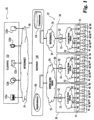
- Fig. 1 depicts pest control system 20 of the present application.
- System 20 includes a pest control monitoring arrangement 22 that communicates with a central pest data management server 120 by computer network 24.
- Computer network 24 is more specifically depicted in two nonlimiting forms as a wireless Wide Area Network (WAN) 25 and internet 26 in Fig. 1 .
- a number of clients 122 of server 120 are also depicted that can selectively access server 120 through internet 26.
- Client 122 includes browser subsystem 122a, spreadsheet interface 122b, email interface 122c, Short Message Service (SMS) interface 122d, and other interface subsystems 122e.
- SMS Short Message Service
- Pest control monitoring arrangement 22 includes a number of pest control device groups 30 that each may be installed at a different location to monitor/control one or more types of pests of interest.
- Each pest control device group 30 includes a pest control data collector 32 in a communication gateway 33, and several pest control devices 40.
- Gateway 33 interfaces with server 120 via computer network 24 and interfaces with pest control devices 40 via wireless Local Area Network (LAN) 36.
- Devices 40 each include a communication node 42 that collectively define network 36.
- Each device 40 includes bait 44 in the form of a pest-consumable material, lure, attractant, or the like; however, in other embodiments, an attractant, lure or other form of bait may be absent.
- the depicted embodiment of device 40 further includes pest sensor 46.
- pest control devices 40 may be arranged to monitor/protect a designated building, room, storage area, or region from a pest of concern, such as rodents, termites, bedbugs, other troublesome insects, and various pests attracted to stored grain, animal feed, pharmaceuticals, pharmaceutical components, other biologic materials, or the like. Accordingly, bait 44 and sensor 46 are selected relative to the pest type(s) of interest.
- a pest of concern such as rodents, termites, bedbugs, other troublesome insects, and various pests attracted to stored grain, animal feed, pharmaceuticals, pharmaceutical components, other biologic materials, or the like.
- bait 44 and sensor 46 are selected relative to the pest type(s) of interest.
- Nonlimiting examples of various sensor and bait types for pest control devices are described in commonly owned U.S. Patent Numbers 7,348,890 ; 7,262,702 ; 7,212,129 ; 7,212,112 ; 6,914,529 ; and 6,724,312 . These patents also describe the manner in which different areas are monitored by devices employing
- Pest control device 40 includes electrical circuitry 43.
- Circuitry 43 includes wireless communication circuitry 50 that defines wireless communication node 42.
- circuitry 50 includes RF transceiver 52 that in turn includes transmitter (TXR) 54 and receiver (RXR) 56.
- Circuit 50 further includes communication antenna 58.
- TXR transmitter
- RXR receiver
- Circuit 50 further includes communication antenna 58.
- transmitter 54 and receiver 56 can be provided in the same integral unit.
- transceiver 52 is defined by independent transmitter 54 and receiver 56 units that collectively provide both transmission and reception functionality.
- Node 42 further includes power management circuitry 60 and controller 70.
- Circuitry 60 includes electrical power source 62 in the form of one or more electrochemical cells or battery 64. Circuitry 60 conditions and provides electrical power to node 42 and sensor 46 as needed.
- Controller 70 includes memory 72.
- Controller 70 can be an electronic circuit comprised of one or more components, including digital circuitry, analog circuitry, or both. Controller 70 may be a software and/or firmware programmable type; a hardwired, dedicated state machine; or a combination of these. In one embodiment, controller 70 is a programmable microcontroller solid-state integrated circuit that integrally includes a processing unit and memory 72. Nonlimiting examples include model nos. MSP430F147 and MSP430F149 provided by Texas Instruments Incorporated.
- Memory 72 can be comprised of one or more components and can be of any volatile or nonvolatile type, including the solid state variety, the optical media variety, the magnetic variety, a combination of these, or such different arrangement as would occur to those skilled in the art.
- controller 70 can be arranged to distribute processing among such units, and/or to provide for parallel or pipelined processing if desired. Controller 70 functions in accordance with operating logic defined by software and/or firmware programming, hardware, or a combination of these.
- memory 72 stores program instructions that are executed by one or more processing units of controller 70 to embody at least a portion of this operating logic. Alternatively or additionally, memory 72 stores data that is manipulated by the operating logic of controller 70.
- Controller 70 can include signal conditioners, signal format converters (such as analog-to-digital and digital-to-analog converters), limiters, clamps, filters, dedicated timers, and the like as needed to perform various operations described in the present application. Indeed, in one form, controller 70, wireless communication circuitry 50 and power management circuitry 60 are at least partially defined by the same integrated circuit device.
- Pest sensor 46 is electrically coupled to controller 70 to provide a corresponding signal indicative of pest presence and/or activity.
- sensor 46 provides an electrical input to an analog-to-digital converter (ADC) included in controller 70.
- ADC analog-to-digital converter
- Pest sensor 46 is associated with bait 44 that may be of a food or other material commonly consumed by pests of interest and/or a lure, attractant, or the like. It should be appreciated that as used herein, bait 44 may or may not include a pesticide and may or may not be intended to be more attractive to pests of interest compared to other materials in proximity.
- pest interaction with bait 44 triggers a change in the signal sent by sensor 46. Typically, detection is triggered by a variation in electrical current or voltage.
- such variation results from a change in electrical conductivity/resistance of one or more elements of sensor 46 in correspondence to pest presence.
- a detection signal could be generated based on electrical capacitance, magnetism, an acoustic characteristic, or optical change -- just to name a few alternatives.
- Commonly owned U.S. Patent Numbers 7,348,890 ; 7,262,702 ; 7,212,129 ; 7,212,112 ; 6,914,529 ; and 6,724,312 describe several such sensing techniques. It should be appreciated that while one pest sensor 46 is indicated in Fig. 2 , in other arrangements multiple pest sensors may be utilized with inputs provided to controller 70 and/or a different device. Furthermore, in other alternative arrangements, bait 44 may be absent.
- pest control devices 40 are configured to operate with a standard battery power source for at least two years, communicating only a relative small amount of data routinely (such as an average of six times per day), with a transmission distance minimum of about 10 meters under very poor conditions and greater than 100 meters under favorable conditions. Nonetheless, in other arrangements any or all of these aspects could vary.
- pest control device 40 takes the form of an in-ground station with an electrically conductive pathway that is altered by termite consumption or displacement to trigger detection. With this arrangement, pesticide may not be delivered until termite presence is verified, although immediate pesticide application and/or above-ground monitoring may be utilized additionally or alternatively. Some rodent applications tend to favor extermination upon detection using a pesticide, mechanical force, and/or electrocution.
- Fig. 3 a form of pest control device that integrates sensor 46 with snap-type of rodent trap 90; where like reference numerals refer to like features previously described.
- sensor 46 more specifically includes a flexible detection member 46a with an electrical resistance that varies depending on the degree of its mechanical deflection/flexure.
- Trap 90 includes a base housing 92 that is pivotally coupled to spring 94.
- Spring 94 is held in place by trap pin 95 as shown in Fig. 3 . In this configuration, if a rodent applies sufficient downward pressure on bait plate 44a, pin 95 is displaced and spring 94 is released to pen the rodent between the spring 94 and base housing 92.
- member 46a changes in response to the displacement of pin 95, causing a change in its electrical resistance.
- Member 46a is electrically coupled to circuitry 43 to provide a corresponding signal indicative of the triggering of the trap and rodent detection.
- Circuitry 43 resides in chamber 96 defined by base housing 92.
- rodent and/or other pest control devices may include a pressure-sensitive pad to detect presence. Further, it should be appreciated that while pest presence is typically the detection goal, any activity/actuation of sensor 46 may be of interest for a given pest control scheme.
- circuitry 43 further includes temperature sensor 74 coupled to controller 70, which, without limitation could be a thermistor, a thermocouple, or the like that provides an analog input to an ADC unit within controller 70.
- a moisture sensor may be included in addition to or in lieu of temperature sensor 74.
- neither of these sensor types is present.
- Switch 76 is arranged to respond to a magnetic field when magnetic field source 78 is in close proximity thereto.
- magnetic field source 78 is provided in the form of a hand-held wand 79.
- Indicator 80 includes two Light Emitting Diodes (LEDs) 82 and 84 each of a different color. In one particular nonlimiting example, one of LEDs 82 and 84 is red, while the other of LEDs 82 and 84 is green. The operation of these features is further described hereinafter in connection with Fig. 4 ; however, further aspects to gateway 33 are first described in connection with Fig. 5 .
- LEDs Light Emitting Diodes
- switch 76 may be of a mechanical variety, such as a pushbutton, rotary, slider, or toggle type; a capacitive proximity type, an optic type, or a thermally activated type --just to name a few possibilities.
- rodent trap activation was demonstrated with a pushbutton form of switch.
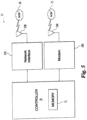
- Gateway 33 is further depicted; where like reference numerals refer to like features previously described.
- Gateway 33 includes controller 70 with memory 72.
- Gateway 33 further includes a wireless network interface 250 with antenna 258 to communicate with the wireless communication network 36, as defined by a corresponding pest control group 30; and modem 260 with antenna 268 to interface with a wireless WAN network 25.
- controller 70 is a general purpose laptop or personal computer running an application to define a communication gateway
- interface 250 is of a local area network (LAN) type
- modem 260 utilizes General Packet Radio Service (GPRS) through the Global System for Mobile communications (GSM) protocol.
- GPRS General Packet Radio Service
- GSM Global System for Mobile communications
- controller 70 is of a microcontroller type, such as model no. C805F120 provided by Cygnal Technologies; interface 250 is a 25 milliWatt (mW) WAVENIS-compatible wavecard provided by Coronis Systems; and modem 260 is of a hardwired dial-up and/or coaxial cable type (not shown).
- a microcontroller type such as model no. C805F120 provided by Cygnal Technologies
- interface 250 is a 25 milliWatt (mW) WAVENIS-compatible wavecard provided by Coronis Systems
- modem 260 is of a hardwired dial-up and/or coaxial cable type (not shown).
- pest control devices 40 of a respective group 30 are installed to protect the building/area of interest, which includes physically positioning each of pest control devices 40 and establishing wireless network 36.
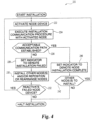
- Fig. 4 depicts one mode of establishing network 36 in flowchart form as network installation procedure 220; where like reference numerals refer to like features previously described.
- Procedure 220 can be implemented in accordance with operating logic executed by controller 70 of at least some of the pest control devices 40 and gateway 33 for the respective group 30.
- Procedure 220 logically associates each node 42 with a corresponding gateway 33.
- each node 42 attempts to establish a reliable communications path to the respective gateway 33, either directly or by relaying its messages through one or more other nodes 42 of the same group 30, and provides the installer feedback concerning its success or failure in finding a reliable communications path.
- a selected node 42 is activated.
- a magnetic field from source 78 is placed in close proximity.
- switch 76 changes state and triggers network establishment for such selected node 42.
- an operator triggers node network installation activation by applying force to a mechanical form of switch 76, such as pushing a momentary, pushbutton switch type.
- procedure 220 continues with operation 224.
- the selected node 42 executes a search routine to identify a reliable communication path to its corresponding gateway 33.
- This routine is typically defined by operating logic executed by controller 70 of the selected node. In one implementation, this routine is at least partially provided in the form of firmware instructions stored in memory 72 and uses a SEARCH REQUEST function included in the Service Discovery Protocol (SDP) code library.
- SDP Service Discovery Protocol
- This function can operate with a variety of criteria for the requested search, including a Class of Device (COD) code identifying the specific gateway 33 to which connection is desired, quality of service (QoS) criteria based on signal strength or the like, and criteria controlling the preferred method of making the connection, either directly to gateway 33 or through one or more other nodes 42 of its pest control device group 30.
- COD Class of Device
- QoS quality of service
- indicator 80 provides an output reflecting this status.
- this output includes LEDs 82 and 84 both blinking at approximately a 10 Hertz (Hz) rate; however, other outputs and/or no output may be provided in correspondence to operation 224 in other embodiments.
- Operation 224 first attempts to find a direct communications path with the corresponding gateway 33 provided it meets specified quality of service (QoS) criteriasuch as signal strength. If a direct path meeting the search criteria is not found, then operation 224 attempts to find a communications path to gateway 33 through other nearby nodes 42 that have already gone through the network installation procedure 220 (if any).
- QoS quality of service
- the criteria for these "indirect” communication paths can be different than those for direct connections, and take into account, in addition to signal strength, how many "hops" are required and/or how many other devices might already be routed through a given node 42 operating as a repeater.
- a limit may be set on the number of communication hops required to reach the corresponding gateway 33, a limit may be set on the number of relaying/repeating nodes 42 involved in a given communication pathway, and/or a limit may be set on how may nodes 42 depend on a specific node 42 to relay communication.
- Procedure 220 continues with conditional 226 that tests whether the desired communication path has been established. If the test of conditional 226 is affirmative (yes), data designating the communication path is stored and a success code is returnedreflecting that a direct or indirect path meeting the search criteria has been found. Further, using the identified communication path, the selected node 42 communicates a unique identifier (such as a unique multibit identification code) to its corresponding gateway 33 of the same group 30.
- Procedure 220 continues with operation 240 to provide an output indicating success with indicator 80. In one form, this output includes illuminating one of LEDs 82 or 84, such as a green LED, for a specified period of time (such as 10 seconds, for example).
- procedure 220 continues with conditional 242 to determine if there are any more nodes 42 to install. If not, then procedure 220 halts. If there are further nodes to install, procedure 220 returns to operation 222 to select and activate the next node 42 for network installation.
- operation 224 returns a failure code, and the test of conditional 226 is negative (no).
- operation 228 is performed in which indicator 80 provides an operator output reflecting this negative/failure status.
- this output includes illuminating one of LEDs 82 or 84 different than for operation 240, such as a red LED, for a specified period of time (such as 10 seconds, for example).
- Procedure 220 proceeds from operation 228 to operation 230.
- operation 230 the operator installs one or more other nodes 42 to serve as repeaters and/or repositions the selected node 42 to provide better conditions for network establishment. It should be appreciated that the successful installation of any other node 42 during operation 230 includes the repetition of operations 222, 224, and 240 and conditionals 226 and 242 for each, and likewise, any that were not successful would result in execution of operations/conditional 222-230.
- conditional 232 is reached. Conditional 232 tests whether the node 42 that failed initialization should be reactivated for another attempt.
- this test would be affirmative (yes), causing procedure 220 to return to operation 222 to reactivate it; however, under certain circumstances it may be determined to abort installation of a given node 42. Such circumstances may include several failed attempts to install or the successful installation of the desired number and/or arrangement of nodes 42 already, such that the failed node 42 need not be installed. In this case, the test of conditional 232 is negative (no) and procedure 220 halts.
- each pest control device 40 and gateway 32 perform certain operations on a routine basis.
- each node 42 participating in network 36 has a low-power consumption sleep mode and at least one "awake" mode.
- the sleep mode is performed based on an internal sleep timer provided by controller 70, that allows the node 42 to significantly reduce its power consumption during idle periods and accordingly enables longer service life.
- the transceiver 52 and/or other peripherals are typically turned off to conserve power.
- a wake-up is triggered.
- a sleep timer is programmed to wake-up controller 70 every 100 milliseconds (10 times per second), and the operating logic, as defined at least in part by controller firmware, is divided into time-based tasks, some of which are executed every wakeup period (100 milliseconds) and others that are executed every tenth wakeup (1 second).
- node 42 includes an internal, multi-channel 12-bit A/D converter for measuring analog signals from external sources over three different channels. One channel is used for pest sensor 46 input, a second channel is used for temperature sensor 74 input, and a third channel is connected to battery 64 to report on its status. The resulting digital values are stored in memory 72 and are compared against designated limits for LOW FAULT, LOW ALARM, LOW WARNING, HIGH WARNING, HIGH ALARM, and HIGH FAULT conditions.
- FAULT, WARNING, or ALARM condition If any FAULT, WARNING, or ALARM condition is detected, an event message is provided for transmission to gateway 33 indicating the affected channel/source, condition (FAULT, WARNING, or ALARM), and the measured value. Any or all of these condition tests may be optionally disabled. Hysterisis can be applied to the condition tests to prevent multiple event messages from being prepared and transmitted during the pendency of the condition. Further, pest sensor 46 input may be processed as needed to reduce the likelihood of an undesired outcome due to noise, activity of a nontargeted pest in the vicinity of the sensor, or slow, gradual changes with temperature. These type of adjustments may be particularly desirable for a flexible resistance-type sensor like that is associated with trap 90.
- DIFF is then compared against a programmable threshold value. If DIFF exceeds the threshold value, the sensor is determined to be "active" and a "hit" is registered by incrementing the value of a HIT COUNTER maintained by the operating logic. If DIFF does not exceed the threshold value, the HIT COUNTER is decremented until it reaches a terminal value of zero. Further, for this implementation, operating logic of controller 70 maintains a 6.4 second sliding time "aperture" over which the value of HIT COUNTER is examined. If HIT COUNTER exceeds a programmable threshold any time within this sliding 6.4 second interval, the operating logic interprets the condition as a rodent hit, and it prepares an event message for transmission indicating the active condition. By adjusting the programmable thresholds for DIFF and HIT COUNTER terminal values, this approach adjusts sensitivity of the rodent sensor, reducing false alarms and ensuring that true active conditions are detected and acted upon.
- the 100 millisecond wake-up can also be used to scan for switch 76 activation and to provide for a blinking pattern of LED 82 and/or 84 as desired.
- this embodiment includes another wake-up mode for less frequently performed tasks. These tasks may include management of transceiver 52 and processing of inbound and outbound messages over the wireless communication path to gateway 33. Accordingly, controller 70 directs that receiver 56 listen for any possible transmissions from gateway 33 or other nodes 42 within communications range. Gateway 33, either directly or by routing its message through other nodes 42, may request status information of the subject node 42 by issuing a POLL REQUEST. If a valid POLL REQUEST is received, controller 70 prepares and sends a response packet including information about the operating status and sensor condition of the subject node 42 via transmitter 54.
- Such tasks further include a determination of whether the subject node 42 is being asked by a neighboring node 42 to relay a message according to routes established during installation of network 36. If such a request is made, controller 70 prepares and transmits the relay message via transceiver 52. In addition, on this less frequent basis, any event messages prepared during the more frequently performed tasks are sent via transmitter 54, and network maintenance/repair operations may be performed as further described hereinafter.
- the operating logic of node 42 further includes a technique to re-form communications paths that become unreliable or unusable. To the extent needed, such self-healing may be performed on a less frequent basis (every second for example). Self-healing may occur due to the removal or failure of a relaying node 42 in an established path, or the introduction of an obstruction.
- node 42 determines the need to self-heal its communication path by maintaining a timer that is reset upon the receipt of a valid POLL REQUEST message from the corresponding gateway 33. The value of this timer is tested against a threshold value. If the timer reaches this threshold, the subject node 42 communication path is deemed to be lost, and a re-installation process is performed.
- This reinstallation is like that described in connection with procedure 220 of Fig. 4 , starting with operation 224, except that operator activation of switch 76 is not necessary to perform path reestablishment, and reinstallation may be repeated a given number of times before declaring failure.
- the subject node 42 retries installation up to 3 more times at an interval equal to the programmable threshold value for the POLL REQUEST timer before declaring a failure.
- an operator-activated switch can be used to cause the subject node 42 to prepare and transmit a message to gateway 33 indicating that it is being removed from service.
- the gateway 33 removes the node's unique ID from its database of active nodes to halt subsequent polling.
- switch 76 could be used to signal removal if activated after successful addition to network 36 is indicated and/or by repeated actuation such that repeated actuation within a given time period toggles between a network install and node removal, or the like.
- a additional switch or other activation device may be utilized (not shown).
- node 42 may include more or fewer waking task modes with or without different frequencies, durations, or the like; may not have distinct sleep and wake modes, may alternatively or additionally be responsive to periodic or aperiodic polling inputs and/or interrupt type triggers to perform at least some tasks, and/or may perform more, fewer, or different tasks as required.
- network 36 may be at least partly predefined, rather than node-determined, may not include some or all of operator indicators, may not be self-healing, and/or may not provide for node removal.
- certain nodes are transmit-only types that send sensor signals to other nodes capable of receiving and transmitting.
- Such other nodes may be dedicated communication routers with different sensing functionality than the transmit-only nodes (such as less sensing capability).
- these routers form a communication backbone between the remaining nodes and gateway 33.
- Gateway 33 serves as a data collector 32 in which status and event information from communicating nodes 42 is gathered. Gateway 33 communicates this information to centrally located data management server 120 hosting database 124. Server 120 provides for data visualization, analysis, reporting, and notification applications as further described in connection with Fig. 6 .
- communications between gateway 33 and nodes 42 of a given group 30 take place via a wireless local area network 36, and between gateway 33 and server 120 via a wireless wide area network (WAN) using Internet Protocol (IP) over General Packet Radio Service (GPRS).
- IP Internet Protocol
- GPRS General Packet Radio Service
- hardwired telephone and/or fiber or coaxial cable connection could be used to interface gateway 33 to a computer network 24 connection with server 120, and/or other protocols and communication subsystems may be utilized.
- Gateway communications may be of a routine, periodically scheduled type, or of an event/condition-driven type. Additionally, customer or administrator initiated queries or updates may be delivered to nodes 42.
- "dowmlink" communications from server 120 to gateway 33 utilize User Datagram Protocol (UDP)
- "uplink" communications from gateway 33 to server 120 utilize File Transfer Protocol (FTP).
- FTP File Transfer Protocol
- this nonlimiting implementation provides operating logic for gateway 33 as a collection of software tasks written in C# under the Microsoft Windows XP multithreading environment provided by Windows XP and the .NET Framework. A description of several exemplary tasks for this implementation are described as follows:
- Server 120 provides various virtual/logical components to allow sensor and node information from geographically disbursed gateways 33 to be aggregated into database 124.
- Server 120 has the ability to communicate with all remote pest control device groups 30, evaluate resulting data, and take corresponding actions using an Application Service Provider (ASP) model.
- ASP Application Service Provider
- server 120 collects the information from the various sites (groups 30), aggregates and processes this information and determines what information needs to be forwarded to a customer.
- server 120 facilitates a data archive, notification and reporting process.
- Selected server functional components, as defined by software or other operating logic executed by server 120, are listed as follows:
- server 120 Once an on-site technician installs all the nodes 42 for a given gateway 33, the site installation and configuration data is received by server 120 from the gateway 33. The data is then parsed at server 120 and stored in database 124. If a change to the configuration is necessary, the stored configuration data is modified and sent to the gateway 33. Gateway 33 will then retrieve this data and compare the modifications to implement any changes. Server 120 regularly receives event and sensor data from the gateway 33 of each group 30 and stores the values in the database. As new events take place at sensors 46, the corresponding data is sent to server 120 that performs notification services via module 120f to those recipients that have subscribed to the information. On a periodic basis (such as once a week), reports on trap activity and battery levels are also dispatched to recipients utilizing reporting services module 125.
- sensor and node information is uploaded to server 120, it is available to the customer.
- Several methods are available for the customer to retrieve this information, depending on specified criteria, subscription level, and the nature of subsequent management action.
- Clients 122 (see Fig. 1 ) embody several customer interface options.
- a password-protected web portal is provided to customers where they may log in to observe their corresponding sites/groups 30, generate reports with reporting services module 125, and observe the current status or summaries of recent events through a "dashboard" type of view.
- sensors 46 which by either its nature (say a moisture sensor) or customer interest (say a rodent station in food processing facility) require that event notification be nearly instantaneous, customers may choose to have notifications sent via e-mail, text message, fax or phone message (via clients 122c and/or 122d, for example).
- This alarm process can be managed interactively by responding to a server generated email or SMS communication, or by logging into the secure web portal.
- customers may choose to have summary reports delivered through spreadsheet reports or physical mailings on a scheduled basis.
- customer reports of site activity are customized to include customer-requested information on a requested schedule.
- Parameters governing how system 20 reacts to collected sensor information can be selected and set by the customers through a web interface. Such parameters include the time frame for notifications of a given sensor type, the delivery mechanism of any alerts, the scheduling of site status reports, etc. These may be updated and changed at any time by the customer. If an application is such that any action may be taken without direct human presence/intervention, such as flipping a switch, the system is capable of initiating such action as specified by customer need.
- the data can be presented in a transport that allows integration into a customer business system.
- one further embodiment includes: operating a pest control system including a plurality of pest control devices and a data collector, the pest control devices each including a respective pest attractant, a respective sensor, and a respective wireless communication circuit; wirelessly transmitting sensor information from the respective sensor of a first one of the pest control devices to a second one of the pest control devices; and wirelessly relaying the sensor information from the second one of the pest control devices to the data collector.
- a further embodiment includes: a pest control system with a plurality of pest control devices and a data collector.
- the pest control devices each include a respective sensor and a respective wireless communication circuit.
- the system further includes means for wirelessly transmitting sensor information from the respective sensor of the first one of the pest control devices to a second one of the pest control devices, and means for wirelessly providing the sensor information from the second one of the pest control devices to the data collector.
- Another embodiment comprises: providing a pest control system including a data collector and several pest control devices that each include a respective sensor and a respective wireless communication circuit; activating a network installation mode of operation of a selected one of the pest control devices; attempting to establish a wireless communication link with a pest control system communication network during the network installation mode, providing a first type of output to an operator if the wireless communication link is established; and providing a second type of output to the operator if the wireless communication link is not established.
- Still another embodiment includes: a pest control system with a data collector and several pest control devices that each include a respective sensor and a respective wireless communication circuit. Also included are means for applying the magnetic field proximate to a selected one of the pest control devices, means for attempting to establish a wireless communication link with a pest control system communication network in response to the magnetic field, means for providing a first type of output to an operator if the wireless communication link is established, and means for providing a second type of output to the operator if the wireless communication link is not established.
- Yet a further embodiment is directed to a pest control device that includes a pest sensor operable to provide one or more signals representative of pest detection and circuitry with a wireless communication transceiver coupled to the pest sensor to transmit information corresponding to the pest detection.
- This circuitry further includes a component responsive to a magnetic field proximate to the pest control device to operate the transceiver in an installation mode and a controller to execute operating logic to establish a wireless communication link with one or more devices during the installation mode.
- an indicator coupled to the circuitry to provide a first operator output indicative of establishment of the wireless communication link if the attempt succeeds and the second operator output indicative of failure to establish the wireless communication link.
- a further embodiment includes: the first pest control device group including a plurality of wireless communication nodes that are each provided with a corresponding pest sensor and a first gateway to receive sensor data from the corresponding sensor of each of the wireless communication nodes.
- One or more of the wireless communication nodes includes the respective controller operating logic to define wireless communication network between the wireless communication nodes.
- the wireless communication network includes a first subset of the node to relay sensor information to the first gateway from a second subset of the node.
Landscapes
- Life Sciences & Earth Sciences (AREA)
- Pest Control & Pesticides (AREA)
- Engineering & Computer Science (AREA)
- Insects & Arthropods (AREA)
- Wood Science & Technology (AREA)
- Zoology (AREA)
- Environmental Sciences (AREA)
- Computer Networks & Wireless Communication (AREA)
- Signal Processing (AREA)
- General Health & Medical Sciences (AREA)
- Health & Medical Sciences (AREA)
- Toxicology (AREA)
- General Physics & Mathematics (AREA)
- Physics & Mathematics (AREA)
- Computing Systems (AREA)
- Medical Informatics (AREA)
- Chemical & Material Sciences (AREA)
- Immunology (AREA)
- Pathology (AREA)
- Analytical Chemistry (AREA)
- Biochemistry (AREA)
- Catching Or Destruction (AREA)
- Telephonic Communication Services (AREA)
- Selective Calling Equipment (AREA)
Claims (12)
- System, umfassend:eine erste Schädlingsbekämpfungsvorrichtungsgruppe (30), beinhaltend eine Vielzahl von Drahtloskommunikationsknoten (42), wobei jeder der Drahtloskommunikationsknoten mit einem entsprechenden Schädlingssensor (46) bereitgestellt ist, der dafür ausgelegt ist, ein entsprechendes Signal bereitzustellen, das Schädlingsaktivität anzeigt; undein erstes Gateway (33) zum Empfangen von Sensordaten vom entsprechenden Schädlingssensor (46) jedes der Drahtloskommunikationsknoten, wobei jeder der Drahtloskommunikationsknoten (42) eine entsprechende Steuerung (70) zum Ausführen von Betriebslogik beinhaltet, zu dem Zweck, ein Drahtloskommunikationsnetz (36) zwischen den Drahtloskommunikationsknoten (42) zu definieren, wobei das Drahtloskommunikationsnetz (36) eine erste Teilmenge der Drahtloskommunikationsknoten zum Weiterleiten von Sensorinformationen von einer zweiten Teilmenge von Drahtloskommunikationsknoten an das erste Gateway (33) beinhaltet, wobei sich die zweite Teilmenge von der ersten Teilmenge unterscheidet.
- System nach Anspruch 1, wobei eine Schädlingsbekämpfungsvorrichtung (40) den Drahtloskommunikationsknoten (42) definiert, wobei die Schädlingsbekämpfungsvorrichtung umfasst: einen Schädlingssensor (46); eine entsprechende Drahtloskommunikationsschaltung (50); und die Steuerung.
- System nach Anspruch 2, wobei die Schädlingsbekämpfungsvorrichtung (40) ferner einen Schädlingsköder (44) umfasst.
- System nach Anspruch 3, wobei der entsprechende Schädlingsköder (44) einen Lockstoff für mindestens eines von Bettwanzen und Termiten beinhaltet und der entsprechende Schädlingssensor (46) dazu dient, Insektenaktivität zu erfassen.
- System nach Anspruch 3, wobei der entsprechende Schädlingsköder (44) einen Lockstoff für Nagetiere beinhaltet und der entsprechende Schädlingssensor (46) dazu dient, Nagetieraktivität zu erfassen.
- System nach Anspruch 1, ferner umfassend:ein Computernetz (24), das mit dem ersten Gateway (33) kommuniziert; undeinen Datenverwaltungsserver (120), der mit dem Computernetz (24) zum Empfangen und Speichern der Sensordaten kommuniziert; undeinen Benutzerzugriffs-Client (122), der mit dem Computernetz (24) zum Zugriff auf die im Datenverwaltungsserver (120) gespeicherten Informationen verbunden ist.
- System nach Anspruch 6, wobei der Datenverwaltungsserver (120) so strukturiert ist, dass er Programmieranweisungen ausführt, die folgende Elemente definieren: eine Datenbank (124) zum Speichern von Daten, die vom ersten Gateway (33) empfangen werden, eine Benachrichtigungsroutine zum Bereitstellen von Benachrichtigungen über einen oder mehrere Zustände, die durch die Sensordaten angezeigt werden, eine Berichterstellungsroutine und eine Datenanalyseroutine.
- System nach Anspruch 1, ferner umfassend:eine zweite Schädlingsbekämpfungsvorrichtungsgruppe (30), beinhaltend eine Vielzahl anderer Drahtloskommunikationsknoten (42), die jeweils mit einem unterschiedlichen Schädlingssensor (46) gekoppelt sind; undein zweites Gateway (33) zum Empfangen unterschiedlicher Sensordaten über ein anderes Drahtloskommunikationsnetz (36), das zwischen den anderen Drahtloskommunikationsknoten (42) definiert ist.
- System nach Anspruch 1, wobei jeder der Drahtloskommunikationsknoten (42) zur ersten Teilmenge gehört und einen Drahtlos-Sender-Empfänger (52) zum Weiterleiten der Sensorinformationen beinhaltet.
- System nach Anspruch 1, wobei jeder der Drahtloskommunikationsknoten (42) zur zweiten Teilmenge gehört und einen Drahtlossender (54) beinhaltet.
- System nach Anspruch 2, wobei die Betriebslogik in Form von Programmieranweisungen vorliegt, die in einem in der Schädlingsbekämpfungsvorrichtung (40) beinhalteten Speicher (72) gespeichert sind.
- System nach Anspruch 2, wobei die Schädlingsbekämpfungsvorrichtung (40) ferner eine auf ein Magnetfeld reagierende Komponente (76) umfasst, zu dem Zweck, einen Installationsbetriebsmodus der Schädlingsbekämpfungsvorrichtung (40) als Reaktion auf ein Magnetfeld in ihrer Nähe auszulösen.
Applications Claiming Priority (3)
| Application Number | Priority Date | Filing Date | Title |
|---|---|---|---|
| US19146108P | 2008-09-09 | 2008-09-09 | |
| PCT/US2009/005056 WO2010030346A1 (en) | 2008-09-09 | 2009-09-09 | Networked pest control system |
| EP09789281.4A EP2323478B1 (de) | 2008-09-09 | 2009-09-09 | Vernetzwerktes schädlingsbekämpfungssystem |
Related Parent Applications (1)
| Application Number | Title | Priority Date | Filing Date |
|---|---|---|---|
| EP09789281.4A Division EP2323478B1 (de) | 2008-09-09 | 2009-09-09 | Vernetzwerktes schädlingsbekämpfungssystem |
Publications (2)
| Publication Number | Publication Date |
|---|---|
| EP3207797A1 EP3207797A1 (de) | 2017-08-23 |
| EP3207797B1 true EP3207797B1 (de) | 2023-06-07 |
Family
ID=41460948
Family Applications (2)
| Application Number | Title | Priority Date | Filing Date |
|---|---|---|---|
| EP09789281.4A Active EP2323478B1 (de) | 2008-09-09 | 2009-09-09 | Vernetzwerktes schädlingsbekämpfungssystem |
| EP17163236.7A Active EP3207797B1 (de) | 2008-09-09 | 2009-09-09 | Vernetzwerktes schädlingsbekämpfungssystem |
Family Applications Before (1)
| Application Number | Title | Priority Date | Filing Date |
|---|---|---|---|
| EP09789281.4A Active EP2323478B1 (de) | 2008-09-09 | 2009-09-09 | Vernetzwerktes schädlingsbekämpfungssystem |
Country Status (13)
| Country | Link |
|---|---|
| US (4) | US8026822B2 (de) |
| EP (2) | EP2323478B1 (de) |
| JP (2) | JP5580316B2 (de) |
| CN (1) | CN102143683B (de) |
| AU (1) | AU2009292169B2 (de) |
| BR (1) | BRPI0918620A2 (de) |
| ES (2) | ES2954990T3 (de) |
| MY (1) | MY164404A (de) |
| PH (1) | PH12013501735A1 (de) |
| PL (1) | PL2323478T3 (de) |
| PT (1) | PT2323478T (de) |
| SG (1) | SG10201600521WA (de) |
| WO (1) | WO2010030346A1 (de) |
Cited By (1)
| Publication number | Priority date | Publication date | Assignee | Title |
|---|---|---|---|---|
| NL2037555B1 (en) * | 2024-04-26 | 2025-11-11 | Attack B V | Detection system for an animal trap for mice and rats |
Families Citing this family (100)
| Publication number | Priority date | Publication date | Assignee | Title |
|---|---|---|---|---|
| DE60304049T2 (de) * | 2002-03-29 | 2006-10-26 | Ecolab Inc., Saint Paul | Verfahren und vorrichtung zur automatischen erzeugung von schädlingsfangberichten und zur aufzeichnung zusätzlicher fangparameterdaten |
| US9015987B2 (en) * | 2007-12-27 | 2015-04-28 | New Frequency, Inc. | Telemetry-enabled trap monitoring system |
| US8026822B2 (en) | 2008-09-09 | 2011-09-27 | Dow Agrosciences Llc | Networked pest control system |
| US8291637B2 (en) * | 2009-09-25 | 2012-10-23 | B&G Equipment Company | Rodent trap including presence indicator mechanism |
| US8112934B2 (en) * | 2009-11-24 | 2012-02-14 | Alter Enterprise Llc | Bear trap |
| US20120185569A1 (en) * | 2011-01-14 | 2012-07-19 | Qualcomm Incorporated | Techniques for dynamic task processing in a wireless communication system |
| ITPI20110065A1 (it) * | 2011-06-10 | 2012-12-11 | Davide Bennardo | "un apparato per il rilevamento e l'eventuale allontanamento di roditori" |
| WO2013000028A1 (en) * | 2011-06-30 | 2013-01-03 | Edith Cowan University | Active probe, system and method for pest detection |
| BRPI1104356A2 (pt) * | 2011-11-01 | 2013-09-03 | Attax Dedetizacco Desratizacco Sc Ltda Me | mÉtodo e sistema de controle e eliminaÇço de pragas |
| JP5759889B2 (ja) * | 2011-12-28 | 2015-08-05 | イカリ消毒株式会社 | 通信装置、通信方法およびプログラム |
| CN102542773A (zh) * | 2011-12-31 | 2012-07-04 | 北京佳讯飞鸿电气股份有限公司 | 一种利用远程气象监测实现防灾的系统及其方法 |
| WO2013137919A1 (en) * | 2012-03-12 | 2013-09-19 | Global Ip Holding Co., Llc | Polymodal detection notification and first response pest treatment system |
| US20140075824A1 (en) * | 2012-09-14 | 2014-03-20 | Woodstream Corporation | Wi-fi enabled insect trapping apparatus |
| US9705962B2 (en) | 2012-09-15 | 2017-07-11 | Honeywell International Inc. | Asynchronous reporting system |
| US10992494B2 (en) | 2012-09-15 | 2021-04-27 | Ademco Inc. | Gateway round-robin system |
| US9122255B2 (en) | 2012-09-15 | 2015-09-01 | Honeywell International Inc. | Remote access gateway configurable control system |
| US10514713B2 (en) * | 2012-09-15 | 2019-12-24 | Ademco Inc. | Mailbox data storage system |
| US20140300477A1 (en) * | 2012-09-25 | 2014-10-09 | Woodstream Corporation | Wireless notification systems and methods for electronic rodent traps |
| US20140085100A1 (en) * | 2012-09-25 | 2014-03-27 | Woodstream Corporation | Wireless notification system and method for electronic rodent traps |
| CN102907415A (zh) * | 2012-10-18 | 2013-02-06 | 宁波市白蚁防治所 | 一种通过射频识别监测白蚁危害的电子监测系统 |
| CA2897534C (en) | 2013-01-08 | 2021-06-01 | Semiosbio Technologies Inc. | Monitoring and control systems for the agricultural industry |
| US9614751B2 (en) * | 2013-04-10 | 2017-04-04 | Fujitsu Limited | Optical path computation based on a reachability matrix |
| CN103444678B (zh) * | 2013-07-04 | 2014-10-29 | 大连工业大学 | 一种自适应捕虫方法 |
| US20150084784A1 (en) * | 2013-09-25 | 2015-03-26 | Solutionbee, LLC | Apiary monitoring system |
| US8989053B1 (en) | 2013-11-29 | 2015-03-24 | Fedex Corporate Services, Inc. | Association management in a wireless node network |
| DE202014100239U1 (de) * | 2014-01-21 | 2015-04-24 | Biotec-Klute Gmbh | Vorrichtung zur Detektion von Schädlingsbefall |
| GB2524307B (en) * | 2014-03-20 | 2016-04-20 | Rentokil Initial Plc | Apparatus |
| US9780907B2 (en) | 2014-04-10 | 2017-10-03 | Fujitsu Limited | Memory-efficient matrix-based optical path computation |
| WO2015179899A1 (en) | 2014-05-28 | 2015-12-03 | Pesense Pty Ltd | Pest detection |
| US10453023B2 (en) | 2014-05-28 | 2019-10-22 | Fedex Corporate Services, Inc. | Methods and node apparatus for adaptive node communication within a wireless node network |
| EP3151661B1 (de) * | 2014-06-03 | 2023-03-15 | Anticimex Innovation Center A/S | Schädlingskontrollvorrichtung mit kommunikationsmitteln |
| CN107072186A (zh) * | 2014-11-04 | 2017-08-18 | 美国陶氏益农公司 | 有害生物控制系统及其操作方法 |
| CA2970294C (en) | 2014-12-09 | 2023-12-19 | Oms Investments, Inc. | Electronic bait station monitoring system |
| US11238397B2 (en) | 2015-02-09 | 2022-02-01 | Fedex Corporate Services, Inc. | Methods, apparatus, and systems for generating a corrective pickup notification for a shipped item using a mobile master node |
| US9999212B2 (en) | 2015-02-13 | 2018-06-19 | Delta Five, Llc | Insect traps and monitoring system |
| US9999211B2 (en) | 2015-02-13 | 2018-06-19 | Delta Five, Llc | Insect traps and monitoring system |
| US9664813B2 (en) | 2015-02-13 | 2017-05-30 | Delta Five, Llc | Automated insect monitoring system |
| US11083183B2 (en) * | 2015-06-03 | 2021-08-10 | Servicepro.Net Llc | Sensor station system for pest monitoring |
| US11051504B2 (en) | 2015-07-13 | 2021-07-06 | Basf Corporation | Pest control and detection system with conductive bait matrix |
| GB2545633B (en) * | 2015-10-28 | 2020-09-23 | Pelsis Ltd | Pest trap |
| EP3370517B8 (de) * | 2015-11-05 | 2023-09-06 | Redmayne, John Michael | Falle oder ausgabevorrichtung |
| US10531653B2 (en) * | 2016-02-03 | 2020-01-14 | Iot Sense, Llc | Pest trap monitor |
| WO2017149163A1 (en) * | 2016-03-04 | 2017-09-08 | Arctic Systems Aps | A monitoring device for a snap trap |
| US11241002B2 (en) * | 2016-03-22 | 2022-02-08 | Matthew Jay | Remote insect monitoring systems and methods |
| CA3014870A1 (en) | 2016-03-23 | 2017-09-28 | Fedex Corporate Services, Inc. | Systems, apparatus, and methods for self-adjusting a broadcast setting of a node in a wireless node network |
| WO2017188828A1 (en) * | 2016-04-29 | 2017-11-02 | Nz Autotraps Limited | Improvements to traps and / or bait dispensing apparatus |
| AU2017293656A1 (en) * | 2016-07-08 | 2019-01-17 | Commonwealth Scientific And Industrial Research Organisation | Pest deterrent system |
| WO2018042235A1 (en) * | 2016-09-05 | 2018-03-08 | Futura Gmbh | Method and system for detecting triggering of a trap for small animals |
| WO2017042790A2 (en) * | 2016-09-06 | 2017-03-16 | Universidad Tecnológica De Panamá | System and method of pest alert in crops |
| US20180096581A1 (en) * | 2016-09-30 | 2018-04-05 | Woodstream Corporation | Long range wireless notification system and method for electronic rodent traps |
| CN114246173A (zh) * | 2017-01-06 | 2022-03-29 | 拜尔农作物科学有限合伙人公司 | 用于无线动物诱捕器检测系统的传感器 |
| US20180249696A1 (en) * | 2017-03-02 | 2018-09-06 | Woodstream Corporation | Remote monitoring of live catch rodent traps |
| NL2018579B1 (nl) | 2017-03-24 | 2018-10-03 | Maarten Crezee Hendrik | Val voor het vangen van dieren, in het bijzonder muizen |
| US10152035B2 (en) | 2017-04-12 | 2018-12-11 | Bayer Ag | Value added pest control system with smart learning |
| US10834914B2 (en) | 2017-04-12 | 2020-11-17 | Bayer Ag | Pest control system and associated method |
| US10743531B2 (en) * | 2017-05-03 | 2020-08-18 | Keven Walter Jones | Wireless rodent trap sensor |
| EP3629723B1 (de) | 2017-05-22 | 2022-09-14 | Corteva Agriscience LLC | Selektive detektion von bettwanzen |
| BR112020000157B1 (pt) | 2017-07-07 | 2023-12-12 | Basf Corporation | Sistema de monitoramento de pragas |
| US11564386B2 (en) * | 2017-08-22 | 2023-01-31 | Vm Products, Inc. | Methods and systems of pest management |
| JP7001410B2 (ja) * | 2017-09-27 | 2022-02-03 | 株式会社キーエンス | センサユニット用の補助ユニット |
| AU2018352459B2 (en) * | 2017-10-17 | 2022-10-13 | Geka Solutions Pty Ltd | Pest control system |
| US10477855B2 (en) * | 2017-10-27 | 2019-11-19 | Marc Daniel Power | Rodent bait station having a counting mechanism |
| US10694338B2 (en) | 2017-11-07 | 2020-06-23 | Pica Product Development, Llc | Cellular automated external defibrillator (AED) tracker |
| US10798541B2 (en) | 2017-11-07 | 2020-10-06 | Pica Product Development, Llc | Systems, methods and devices for remote trap monitoring |
| US10909830B1 (en) | 2017-11-07 | 2021-02-02 | Pica Product Development, Llc | Personal emergency alert system, method and device |
| US12256723B2 (en) | 2017-12-21 | 2025-03-25 | Pesense Pty Ltd | Mounting and positioning device for an electronic sensor in a termite monitor |
| GB2570138B (en) * | 2018-01-12 | 2020-07-08 | Spotta Ltd | System and methods |
| US11219204B2 (en) | 2018-02-12 | 2022-01-11 | Woodstream Corporation | Electronic rodent trap with remote monitoring capability |
| US11278020B2 (en) | 2018-02-12 | 2022-03-22 | Woodstream Corporation | Electronic rodent traps with remote monitoring capability |
| CA2995537A1 (en) * | 2018-02-16 | 2019-08-16 | Maxtech Mosquito Control Inc. | Smart bulb |
| CN121961807A (zh) | 2018-05-17 | 2026-05-01 | 埃科莱布美国股份有限公司 | 用于食品安全的系统、方法和计算机可读介质 |
| EP4344540A3 (de) | 2018-06-29 | 2024-08-14 | Smart Wave Technologies, Inc. | Schädlingsbekämpfungssystem mit ereignisüberwachung |
| US11528900B2 (en) | 2018-07-06 | 2022-12-20 | Woodstream Corporation | Wash down sensor for electronic rodent traps and method of preventing false triggering using a wash down sensor |
| US11470836B2 (en) * | 2018-07-25 | 2022-10-18 | Woodstream Corporation | Rodent snap trap interfaced with electronics monitoring system and method of interfacing a snap trap with electronics monitoring system |
| WO2020026270A1 (en) * | 2018-07-30 | 2020-02-06 | Gurpreet Singh | Smart system for continuous trapping, storing and extermination of multiple number of mouse |
| US10477854B1 (en) * | 2018-10-19 | 2019-11-19 | Qianming Yang | Mousetrap with alarming and reminding functions |
| GB2578313B (en) * | 2018-10-22 | 2021-10-13 | Brandenburg Uk Ltd | Intelligent trap and consumables |
| US11864548B1 (en) * | 2018-10-22 | 2024-01-09 | Bell Laboratories, Inc. | Remote sensing repeating rodent trap |
| GB2578312B (en) * | 2018-10-22 | 2022-02-23 | Brandenburg Uk Ltd | Rodent trap and rodent management |
| WO2020097523A1 (en) * | 2018-11-09 | 2020-05-14 | Ecolab Usa Inc. | System and method for pest monitoring and notification |
| JP7706363B2 (ja) * | 2018-11-21 | 2025-07-11 | エコラボ ユーエスエー インコーポレイティド | ナンキンムシの選択的検出 |
| US11147256B2 (en) * | 2018-12-03 | 2021-10-19 | International Business Machines Corporation | Monitoring disease vectors |
| US10849320B2 (en) * | 2019-02-08 | 2020-12-01 | Jace W. Files | Pest trap with disposal container and wireless monitoring |
| JP7181553B2 (ja) * | 2019-02-26 | 2022-12-01 | 東信科学株式会社 | 害虫検知駆除装置及びシステム |
| IT201900004087A1 (it) * | 2019-03-21 | 2020-09-21 | Felicia Margutti | Sistema di monitoraggio e cattura di piccoli mammiferi roditori e relativi procedimenti di installazione e di funzionamento |
| DK180372B1 (en) * | 2019-04-23 | 2021-02-12 | Sensora Aps | An apparatus and method for detecting, monitoring and/or controlling of rat activity |
| SE1930231A1 (en) * | 2019-06-28 | 2020-11-03 | Iot Telltales Ab | A device for determining bedbug activity and a method for detecting bedbugs |
| DK180462B1 (en) * | 2019-07-05 | 2021-05-06 | Anticimex Innovation Center As | Rodent trap |
| BE1028494B1 (nl) * | 2020-07-16 | 2022-02-15 | Strygoo Bv | Inrichting voor het vangen van ongedierte |
| CN111713484B (zh) * | 2020-07-29 | 2022-05-10 | 张露 | 一种智能捕鼠笼 |
| CA3195070A1 (en) * | 2020-10-26 | 2022-05-05 | Precision Planting Llc | Autosteered implement |
| CN112602693B (zh) * | 2020-12-11 | 2022-01-28 | 广西翔泓农业科技有限公司 | 一种基于无人机的农药喷洒装置 |
| US20220192171A1 (en) * | 2020-12-17 | 2022-06-23 | OTS INVESTCO INC. (Ontario Corporation No 00243119) | Pest control system and method for use thereof |
| US12469332B2 (en) | 2021-12-28 | 2025-11-11 | The Joan and Irwin Jacobs Technion-Cornell Institute | Techniques for performing and utilizing frequency signature mapping |
| JP2024046895A (ja) * | 2022-09-26 | 2024-04-05 | 株式会社シー・アイ・シー | 監視機器及び調査システム |
| DK181560B1 (en) * | 2022-12-23 | 2024-05-16 | Anticimex Innovation Center As | A pest control system and a method for building a network of pest control devices |
| DK181441B1 (en) * | 2022-12-28 | 2024-01-15 | Anticimex Innovation Center As | A pest control device, a pest control system and a method for configuring the pest control system |
| US12564185B2 (en) | 2023-02-03 | 2026-03-03 | SIS Development, Inc. | Automatic optimizing pest control substance delivery system |
| DK202370322A1 (en) * | 2023-06-21 | 2025-01-21 | Anticimex Innovation Center As | A method for providing an insect population growth forecast, a monitoring device and a system |
| FR3150930B3 (fr) | 2023-07-13 | 2025-07-18 | Assistance Et Prot Antiparasitaire A P A | Piège à nuisible(s) connecté |
Citations (3)
| Publication number | Priority date | Publication date | Assignee | Title |
|---|---|---|---|---|
| WO2003061175A2 (en) * | 2002-01-10 | 2003-07-24 | Robert Bosch Gmbh | Self-organizing hierarchical wireless network for surveillance and control |
| WO2004021735A1 (en) * | 2002-09-02 | 2004-03-11 | Cesco Co., Ltd. | Remote monitoring system for exterminating pest and a method thereof |
| US20060176169A1 (en) * | 2004-12-17 | 2006-08-10 | The Regents Of The University Of California | System for sensing environmental conditions |
Family Cites Families (32)
| Publication number | Priority date | Publication date | Assignee | Title |
|---|---|---|---|---|
| US6304556B1 (en) | 1998-08-24 | 2001-10-16 | Cornell Research Foundation, Inc. | Routing and mobility management protocols for ad-hoc networks |
| US7026942B2 (en) | 1999-06-08 | 2006-04-11 | Gilberto Cristofori | Method for signalling the presence of prey in traps for vermin and device for carrying out this method |
| US6724312B1 (en) | 1999-07-21 | 2004-04-20 | Daniel Barber | Pest control apparatus and methods |
| US7212112B2 (en) | 1999-07-21 | 2007-05-01 | Dow Agrosciences Llc | Detection and control of pests |
| US7212129B2 (en) * | 1999-07-21 | 2007-05-01 | Dow Agrosciences Llc | Devices, systems, and method to control pests |
| US6914529B2 (en) | 1999-07-21 | 2005-07-05 | Dow Agrosciences Llc | Sensing devices, systems, and methods particularly for pest control |
| CN101116433B (zh) | 1999-07-21 | 2010-06-09 | 道农业科学有限公司 | 虫害控制方法 |
| US7262702B2 (en) | 1999-07-21 | 2007-08-28 | Dow Agrosciences Llc | Pest control devices, systems, and methods |
| US7348890B2 (en) * | 1999-07-21 | 2008-03-25 | Dow Agrosciences Llc | Pest control techniques |
| US6385174B1 (en) | 1999-11-12 | 2002-05-07 | Itt Manufacturing Enterprises, Inc. | Method and apparatus for transmission of node link status messages throughout a network with reduced communication protocol overhead traffic |
| AU8651601A (en) | 2000-08-22 | 2002-03-04 | Eye On Solutions Llc | Remote detection, monitoring and information management system |
| US7020996B2 (en) | 2001-04-06 | 2006-04-04 | Morton Beroza | Method and system for remotely detecting trapped insects |
| CN101023743A (zh) * | 2001-08-09 | 2007-08-29 | 道农业科学有限公司 | 虫害的检测与防治 |
| US7483403B2 (en) | 2002-01-10 | 2009-01-27 | Robert Bosch Gmbh | Protocol for reliable, self-organizing, low-power wireless network for security and building automation systems |
| CN1649492B (zh) * | 2002-03-21 | 2010-12-08 | 美国陶氏益农公司 | 控制害虫的方法和设备 |
| WO2003084321A1 (en) | 2002-03-29 | 2003-10-16 | Ecolab Inc. | Method and apparatus for capacitively sensing pests |
| DE60304049T2 (de) | 2002-03-29 | 2006-10-26 | Ecolab Inc., Saint Paul | Verfahren und vorrichtung zur automatischen erzeugung von schädlingsfangberichten und zur aufzeichnung zusätzlicher fangparameterdaten |
| EP1576528A4 (de) | 2002-10-09 | 2011-05-18 | California Inst Of Techn | Sensor-gewebe |
| US7656300B2 (en) | 2003-06-16 | 2010-02-02 | Rønnau Development ApS | Pest control system |
| US7286056B2 (en) | 2005-03-22 | 2007-10-23 | Lawrence Kates | System and method for pest detection |
| JP2007036665A (ja) * | 2005-07-27 | 2007-02-08 | Matsushita Electric Ind Co Ltd | 無線システムおよび無線ネットワーク設定方法 |
| US7591099B2 (en) | 2005-08-30 | 2009-09-22 | Ecolab Inc. | Bed bug monitor |
| GB0517917D0 (en) | 2005-09-03 | 2005-10-12 | Riwa Ltd | A bait box |
| US7395161B2 (en) * | 2006-02-10 | 2008-07-01 | David Thomas A | Polymodal biological detection system |
| JP4839152B2 (ja) * | 2006-08-04 | 2011-12-21 | 株式会社日立製作所 | センサネットワークシステム及びセンサネットワークのデータ処理方法 |
| US8258966B2 (en) | 2006-11-13 | 2012-09-04 | Syngenta Limited | Pest detector |
| WO2008110801A2 (en) | 2007-03-13 | 2008-09-18 | Syngenta Participations Ag | Methods and systems for ad hoc sensor network |
| US9015987B2 (en) * | 2007-12-27 | 2015-04-28 | New Frequency, Inc. | Telemetry-enabled trap monitoring system |
| US8484386B2 (en) | 2008-01-31 | 2013-07-09 | Intermec Ip Corp. | Systems, methods and devices for monitoring environmental characteristics using wireless sensor nodes |
| US8026822B2 (en) * | 2008-09-09 | 2011-09-27 | Dow Agrosciences Llc | Networked pest control system |
| US8156683B2 (en) | 2009-07-09 | 2012-04-17 | David Slotnick | Wireless rat trap movement detection system |
| US8599026B2 (en) | 2009-11-11 | 2013-12-03 | Nisus Corporation | Animal control system |
-
2009
- 2009-09-08 US US12/584,581 patent/US8026822B2/en active Active
- 2009-09-09 WO PCT/US2009/005056 patent/WO2010030346A1/en not_active Ceased
- 2009-09-09 MY MYPI2011001025A patent/MY164404A/en unknown
- 2009-09-09 EP EP09789281.4A patent/EP2323478B1/de active Active
- 2009-09-09 PL PL09789281T patent/PL2323478T3/pl unknown
- 2009-09-09 ES ES17163236T patent/ES2954990T3/es active Active
- 2009-09-09 BR BRPI0918620A patent/BRPI0918620A2/pt not_active IP Right Cessation
- 2009-09-09 ES ES09789281.4T patent/ES2628214T3/es active Active
- 2009-09-09 AU AU2009292169A patent/AU2009292169B2/en active Active
- 2009-09-09 EP EP17163236.7A patent/EP3207797B1/de active Active
- 2009-09-09 JP JP2011526059A patent/JP5580316B2/ja active Active
- 2009-09-09 PT PT97892814T patent/PT2323478T/pt unknown
- 2009-09-09 SG SG10201600521WA patent/SG10201600521WA/en unknown
- 2009-09-09 CN CN200980134889.XA patent/CN102143683B/zh not_active Expired - Fee Related
-
2011
- 2011-08-19 US US13/213,153 patent/US8830071B2/en active Active
-
2013
- 2013-08-22 PH PH12013501735A patent/PH12013501735A1/en unknown
-
2014
- 2014-07-10 JP JP2014141991A patent/JP5889967B2/ja active Active
- 2014-07-21 US US14/336,529 patent/US9542835B2/en active Active
-
2017
- 2017-01-10 US US15/402,977 patent/US10085133B2/en active Active
Patent Citations (3)
| Publication number | Priority date | Publication date | Assignee | Title |
|---|---|---|---|---|
| WO2003061175A2 (en) * | 2002-01-10 | 2003-07-24 | Robert Bosch Gmbh | Self-organizing hierarchical wireless network for surveillance and control |
| WO2004021735A1 (en) * | 2002-09-02 | 2004-03-11 | Cesco Co., Ltd. | Remote monitoring system for exterminating pest and a method thereof |
| US20060176169A1 (en) * | 2004-12-17 | 2006-08-10 | The Regents Of The University Of California | System for sensing environmental conditions |
Cited By (1)
| Publication number | Priority date | Publication date | Assignee | Title |
|---|---|---|---|---|
| NL2037555B1 (en) * | 2024-04-26 | 2025-11-11 | Attack B V | Detection system for an animal trap for mice and rats |
Also Published As
| Publication number | Publication date |
|---|---|
| US10085133B2 (en) | 2018-09-25 |
| ES2628214T3 (es) | 2017-08-02 |
| JP5889967B2 (ja) | 2016-03-22 |
| PH12013501735B1 (en) | 2015-03-30 |
| US9542835B2 (en) | 2017-01-10 |
| PL2323478T3 (pl) | 2017-09-29 |
| CN102143683A (zh) | 2011-08-03 |
| US20170195824A1 (en) | 2017-07-06 |
| US20140325892A1 (en) | 2014-11-06 |
| US20100134301A1 (en) | 2010-06-03 |
| AU2009292169B2 (en) | 2014-04-03 |
| JP2012501647A (ja) | 2012-01-26 |
| EP2323478A1 (de) | 2011-05-25 |
| JP2014236736A (ja) | 2014-12-18 |
| PT2323478T (pt) | 2017-07-10 |
| BRPI0918620A2 (pt) | 2015-12-01 |
| JP5580316B2 (ja) | 2014-08-27 |
| PH12013501735A1 (en) | 2015-03-30 |
| AU2009292169A1 (en) | 2010-03-18 |
| ES2954990T3 (es) | 2023-11-28 |
| US8026822B2 (en) | 2011-09-27 |
| US20120212338A1 (en) | 2012-08-23 |
| EP3207797A1 (de) | 2017-08-23 |
| MY164404A (en) | 2017-12-15 |
| EP2323478B1 (de) | 2017-03-29 |
| SG10201600521WA (en) | 2016-02-26 |
| US8830071B2 (en) | 2014-09-09 |
| WO2010030346A1 (en) | 2010-03-18 |
| CN102143683B (zh) | 2015-04-22 |
| HK1158015A1 (en) | 2012-07-13 |
Similar Documents
| Publication | Publication Date | Title |
|---|---|---|
| US10085133B2 (en) | Networked pest control system | |
| EP3646728B1 (de) | Systeme und verfahren zur drahtlosen benachrichtigung für elektronische nagetierfallen | |
| AU2014203633B2 (en) | Networked pest control system | |
| JP4862117B2 (ja) | フィールドサーバを利用した電撃パルス計測システム | |
| EP2775447A1 (de) | Verfahren und system zur bekämpfung und beseitigung von schädlingen | |
| US20150351336A1 (en) | Monitoring and Control Systems for the Agricultural Industry | |
| JP2021510303A (ja) | システムおよび方法 | |
| US10629061B2 (en) | Wireless pest management system and method | |
| JP7443382B2 (ja) | 粘着ボードを利用する動物捕獲検出システム | |
| Nibali et al. | Remote monitoring of rodenticide depletion | |
| HK1158015B (en) | Networked pest control system | |
| KR20030032838A (ko) | 원격 방제 시스템 및 그 방법 및 실시간 방제 방법 |
Legal Events
| Date | Code | Title | Description |
|---|---|---|---|
| PUAI | Public reference made under article 153(3) epc to a published international application that has entered the european phase |
Free format text: ORIGINAL CODE: 0009012 |
|
| STAA | Information on the status of an ep patent application or granted ep patent |
Free format text: STATUS: THE APPLICATION HAS BEEN PUBLISHED |
|
| AC | Divisional application: reference to earlier application |
Ref document number: 2323478 Country of ref document: EP Kind code of ref document: P |
|
| AK | Designated contracting states |
Kind code of ref document: A1 Designated state(s): AT BE BG CH CY CZ DE DK EE ES FI FR GB GR HR HU IE IS IT LI LT LU LV MC MK MT NL NO PL PT RO SE SI SK SM TR |
|
| STAA | Information on the status of an ep patent application or granted ep patent |
Free format text: STATUS: REQUEST FOR EXAMINATION WAS MADE |
|
| 17P | Request for examination filed |
Effective date: 20180209 |
|
| RBV | Designated contracting states (corrected) |
Designated state(s): AT BE BG CH CY CZ DE DK EE ES FI FR GB GR HR HU IE IS IT LI LT LU LV MC MK MT NL NO PL PT RO SE SI SK SM TR |
|
| STAA | Information on the status of an ep patent application or granted ep patent |
Free format text: STATUS: EXAMINATION IS IN PROGRESS |
|
| 17Q | First examination report despatched |
Effective date: 20210422 |
|
| RAP3 | Party data changed (applicant data changed or rights of an application transferred) |
Owner name: CORTEVA AGRISCIENCE LLC |
|
| GRAP | Despatch of communication of intention to grant a patent |
Free format text: ORIGINAL CODE: EPIDOSNIGR1 |
|
| STAA | Information on the status of an ep patent application or granted ep patent |
Free format text: STATUS: GRANT OF PATENT IS INTENDED |
|
| RIC1 | Information provided on ipc code assigned before grant |
Ipc: G08C 17/02 20060101ALI20221202BHEP Ipc: H04L 67/125 20220101ALI20221202BHEP Ipc: H04L 67/025 20220101ALI20221202BHEP Ipc: H04W 76/10 20180101ALI20221202BHEP Ipc: H04W 4/70 20180101ALI20221202BHEP Ipc: A01M 31/00 20060101ALI20221202BHEP Ipc: A01M 25/00 20060101ALI20221202BHEP Ipc: A01M 1/20 20060101ALI20221202BHEP Ipc: A01M 1/02 20060101AFI20221202BHEP |
|
| INTG | Intention to grant announced |
Effective date: 20221223 |
|
| GRAS | Grant fee paid |
Free format text: ORIGINAL CODE: EPIDOSNIGR3 |
|
| GRAA | (expected) grant |
Free format text: ORIGINAL CODE: 0009210 |
|
| STAA | Information on the status of an ep patent application or granted ep patent |
Free format text: STATUS: THE PATENT HAS BEEN GRANTED |
|
| AC | Divisional application: reference to earlier application |
Ref document number: 2323478 Country of ref document: EP Kind code of ref document: P |
|
| AK | Designated contracting states |
Kind code of ref document: B1 Designated state(s): AT BE BG CH CY CZ DE DK EE ES FI FR GB GR HR HU IE IS IT LI LT LU LV MC MK MT NL NO PL PT RO SE SI SK SM TR |
|
| REG | Reference to a national code |
Ref country code: GB Ref legal event code: FG4D |
|
| REG | Reference to a national code |
Ref country code: CH Ref legal event code: EP Ref country code: AT Ref legal event code: REF Ref document number: 1571898 Country of ref document: AT Kind code of ref document: T Effective date: 20230615 Ref country code: DE Ref legal event code: R096 Ref document number: 602009064872 Country of ref document: DE |
|
| P01 | Opt-out of the competence of the unified patent court (upc) registered |
Effective date: 20230530 |
|
| REG | Reference to a national code |
Ref country code: LT Ref legal event code: MG9D |
|
| REG | Reference to a national code |
Ref country code: NL Ref legal event code: MP Effective date: 20230607 |
|
| PG25 | Lapsed in a contracting state [announced via postgrant information from national office to epo] |
Ref country code: SE Free format text: LAPSE BECAUSE OF FAILURE TO SUBMIT A TRANSLATION OF THE DESCRIPTION OR TO PAY THE FEE WITHIN THE PRESCRIBED TIME-LIMIT Effective date: 20230607 Ref country code: NO Free format text: LAPSE BECAUSE OF FAILURE TO SUBMIT A TRANSLATION OF THE DESCRIPTION OR TO PAY THE FEE WITHIN THE PRESCRIBED TIME-LIMIT Effective date: 20230907 |
|
| REG | Reference to a national code |
Ref country code: AT Ref legal event code: MK05 Ref document number: 1571898 Country of ref document: AT Kind code of ref document: T Effective date: 20230607 |
|
| REG | Reference to a national code |
Ref country code: ES Ref legal event code: FG2A Ref document number: 2954990 Country of ref document: ES Kind code of ref document: T3 Effective date: 20231128 |
|
| PG25 | Lapsed in a contracting state [announced via postgrant information from national office to epo] |
Ref country code: NL Free format text: LAPSE BECAUSE OF FAILURE TO SUBMIT A TRANSLATION OF THE DESCRIPTION OR TO PAY THE FEE WITHIN THE PRESCRIBED TIME-LIMIT Effective date: 20230607 Ref country code: LV Free format text: LAPSE BECAUSE OF FAILURE TO SUBMIT A TRANSLATION OF THE DESCRIPTION OR TO PAY THE FEE WITHIN THE PRESCRIBED TIME-LIMIT Effective date: 20230607 Ref country code: LT Free format text: LAPSE BECAUSE OF FAILURE TO SUBMIT A TRANSLATION OF THE DESCRIPTION OR TO PAY THE FEE WITHIN THE PRESCRIBED TIME-LIMIT Effective date: 20230607 Ref country code: HR Free format text: LAPSE BECAUSE OF FAILURE TO SUBMIT A TRANSLATION OF THE DESCRIPTION OR TO PAY THE FEE WITHIN THE PRESCRIBED TIME-LIMIT Effective date: 20230607 Ref country code: GR Free format text: LAPSE BECAUSE OF FAILURE TO SUBMIT A TRANSLATION OF THE DESCRIPTION OR TO PAY THE FEE WITHIN THE PRESCRIBED TIME-LIMIT Effective date: 20230908 |
|
| PG25 | Lapsed in a contracting state [announced via postgrant information from national office to epo] |
Ref country code: FI Free format text: LAPSE BECAUSE OF FAILURE TO SUBMIT A TRANSLATION OF THE DESCRIPTION OR TO PAY THE FEE WITHIN THE PRESCRIBED TIME-LIMIT Effective date: 20230607 |
|
| PG25 | Lapsed in a contracting state [announced via postgrant information from national office to epo] |
Ref country code: SK Free format text: LAPSE BECAUSE OF FAILURE TO SUBMIT A TRANSLATION OF THE DESCRIPTION OR TO PAY THE FEE WITHIN THE PRESCRIBED TIME-LIMIT Effective date: 20230607 |
|
| PG25 | Lapsed in a contracting state [announced via postgrant information from national office to epo] |
Ref country code: IS Free format text: LAPSE BECAUSE OF FAILURE TO SUBMIT A TRANSLATION OF THE DESCRIPTION OR TO PAY THE FEE WITHIN THE PRESCRIBED TIME-LIMIT Effective date: 20231007 |
|
| PG25 | Lapsed in a contracting state [announced via postgrant information from national office to epo] |
Ref country code: SM Free format text: LAPSE BECAUSE OF FAILURE TO SUBMIT A TRANSLATION OF THE DESCRIPTION OR TO PAY THE FEE WITHIN THE PRESCRIBED TIME-LIMIT Effective date: 20230607 Ref country code: SK Free format text: LAPSE BECAUSE OF FAILURE TO SUBMIT A TRANSLATION OF THE DESCRIPTION OR TO PAY THE FEE WITHIN THE PRESCRIBED TIME-LIMIT Effective date: 20230607 Ref country code: RO Free format text: LAPSE BECAUSE OF FAILURE TO SUBMIT A TRANSLATION OF THE DESCRIPTION OR TO PAY THE FEE WITHIN THE PRESCRIBED TIME-LIMIT Effective date: 20230607 Ref country code: PT Free format text: LAPSE BECAUSE OF FAILURE TO SUBMIT A TRANSLATION OF THE DESCRIPTION OR TO PAY THE FEE WITHIN THE PRESCRIBED TIME-LIMIT Effective date: 20231009 Ref country code: IS Free format text: LAPSE BECAUSE OF FAILURE TO SUBMIT A TRANSLATION OF THE DESCRIPTION OR TO PAY THE FEE WITHIN THE PRESCRIBED TIME-LIMIT Effective date: 20231007 Ref country code: EE Free format text: LAPSE BECAUSE OF FAILURE TO SUBMIT A TRANSLATION OF THE DESCRIPTION OR TO PAY THE FEE WITHIN THE PRESCRIBED TIME-LIMIT Effective date: 20230607 Ref country code: CZ Free format text: LAPSE BECAUSE OF FAILURE TO SUBMIT A TRANSLATION OF THE DESCRIPTION OR TO PAY THE FEE WITHIN THE PRESCRIBED TIME-LIMIT Effective date: 20230607 Ref country code: AT Free format text: LAPSE BECAUSE OF FAILURE TO SUBMIT A TRANSLATION OF THE DESCRIPTION OR TO PAY THE FEE WITHIN THE PRESCRIBED TIME-LIMIT Effective date: 20230607 |
|
| PG25 | Lapsed in a contracting state [announced via postgrant information from national office to epo] |
Ref country code: PL Free format text: LAPSE BECAUSE OF FAILURE TO SUBMIT A TRANSLATION OF THE DESCRIPTION OR TO PAY THE FEE WITHIN THE PRESCRIBED TIME-LIMIT Effective date: 20230607 |
|
| REG | Reference to a national code |
Ref country code: DE Ref legal event code: R097 Ref document number: 602009064872 Country of ref document: DE |
|
| REG | Reference to a national code |
Ref country code: DE Ref legal event code: R119 Ref document number: 602009064872 Country of ref document: DE |
|
| PLBE | No opposition filed within time limit |
Free format text: ORIGINAL CODE: 0009261 |
|
| STAA | Information on the status of an ep patent application or granted ep patent |
Free format text: STATUS: NO OPPOSITION FILED WITHIN TIME LIMIT |
|
| PG25 | Lapsed in a contracting state [announced via postgrant information from national office to epo] |
Ref country code: DK Free format text: LAPSE BECAUSE OF FAILURE TO SUBMIT A TRANSLATION OF THE DESCRIPTION OR TO PAY THE FEE WITHIN THE PRESCRIBED TIME-LIMIT Effective date: 20230607 |
|
| REG | Reference to a national code |
Ref country code: CH Ref legal event code: PL |
|
| PG25 | Lapsed in a contracting state [announced via postgrant information from national office to epo] |
Ref country code: SI Free format text: LAPSE BECAUSE OF FAILURE TO SUBMIT A TRANSLATION OF THE DESCRIPTION OR TO PAY THE FEE WITHIN THE PRESCRIBED TIME-LIMIT Effective date: 20230607 |
|
| 26N | No opposition filed |
Effective date: 20240308 |
|
| PG25 | Lapsed in a contracting state [announced via postgrant information from national office to epo] |
Ref country code: LU Free format text: LAPSE BECAUSE OF NON-PAYMENT OF DUE FEES Effective date: 20230909 |
|
| REG | Reference to a national code |
Ref country code: BE Ref legal event code: MM Effective date: 20230930 |
|
| PG25 | Lapsed in a contracting state [announced via postgrant information from national office to epo] |
Ref country code: SI Free format text: LAPSE BECAUSE OF FAILURE TO SUBMIT A TRANSLATION OF THE DESCRIPTION OR TO PAY THE FEE WITHIN THE PRESCRIBED TIME-LIMIT Effective date: 20230607 Ref country code: LU Free format text: LAPSE BECAUSE OF NON-PAYMENT OF DUE FEES Effective date: 20230909 Ref country code: MC Free format text: LAPSE BECAUSE OF FAILURE TO SUBMIT A TRANSLATION OF THE DESCRIPTION OR TO PAY THE FEE WITHIN THE PRESCRIBED TIME-LIMIT Effective date: 20230607 |
|
| REG | Reference to a national code |
Ref country code: IE Ref legal event code: MM4A |
|
| PG25 | Lapsed in a contracting state [announced via postgrant information from national office to epo] |
Ref country code: IE Free format text: LAPSE BECAUSE OF NON-PAYMENT OF DUE FEES Effective date: 20230909 |
|
| PG25 | Lapsed in a contracting state [announced via postgrant information from national office to epo] |
Ref country code: CH Free format text: LAPSE BECAUSE OF NON-PAYMENT OF DUE FEES Effective date: 20230930 |
|
| PG25 | Lapsed in a contracting state [announced via postgrant information from national office to epo] |
Ref country code: IE Free format text: LAPSE BECAUSE OF NON-PAYMENT OF DUE FEES Effective date: 20230909 Ref country code: DE Free format text: LAPSE BECAUSE OF NON-PAYMENT OF DUE FEES Effective date: 20240403 Ref country code: CH Free format text: LAPSE BECAUSE OF NON-PAYMENT OF DUE FEES Effective date: 20230930 |
|
| PG25 | Lapsed in a contracting state [announced via postgrant information from national office to epo] |
Ref country code: BE Free format text: LAPSE BECAUSE OF NON-PAYMENT OF DUE FEES Effective date: 20230930 |
|
| PG25 | Lapsed in a contracting state [announced via postgrant information from national office to epo] |
Ref country code: BG Free format text: LAPSE BECAUSE OF FAILURE TO SUBMIT A TRANSLATION OF THE DESCRIPTION OR TO PAY THE FEE WITHIN THE PRESCRIBED TIME-LIMIT Effective date: 20230607 |
|
| PG25 | Lapsed in a contracting state [announced via postgrant information from national office to epo] |
Ref country code: BG Free format text: LAPSE BECAUSE OF FAILURE TO SUBMIT A TRANSLATION OF THE DESCRIPTION OR TO PAY THE FEE WITHIN THE PRESCRIBED TIME-LIMIT Effective date: 20230607 |
|
| PGFP | Annual fee paid to national office [announced via postgrant information from national office to epo] |
Ref country code: ES Payment date: 20241003 Year of fee payment: 16 |
|
| PG25 | Lapsed in a contracting state [announced via postgrant information from national office to epo] |
Ref country code: CY Free format text: LAPSE BECAUSE OF FAILURE TO SUBMIT A TRANSLATION OF THE DESCRIPTION OR TO PAY THE FEE WITHIN THE PRESCRIBED TIME-LIMIT; INVALID AB INITIO Effective date: 20090909 |
|
| PG25 | Lapsed in a contracting state [announced via postgrant information from national office to epo] |
Ref country code: HU Free format text: LAPSE BECAUSE OF FAILURE TO SUBMIT A TRANSLATION OF THE DESCRIPTION OR TO PAY THE FEE WITHIN THE PRESCRIBED TIME-LIMIT; INVALID AB INITIO Effective date: 20090909 |
|
| PGFP | Annual fee paid to national office [announced via postgrant information from national office to epo] |
Ref country code: IT Payment date: 20250825 Year of fee payment: 17 |
|
| PGFP | Annual fee paid to national office [announced via postgrant information from national office to epo] |
Ref country code: GB Payment date: 20250703 Year of fee payment: 17 |
|
| PGFP | Annual fee paid to national office [announced via postgrant information from national office to epo] |
Ref country code: FR Payment date: 20250703 Year of fee payment: 17 |
|
| PG25 | Lapsed in a contracting state [announced via postgrant information from national office to epo] |
Ref country code: TR Free format text: LAPSE BECAUSE OF FAILURE TO SUBMIT A TRANSLATION OF THE DESCRIPTION OR TO PAY THE FEE WITHIN THE PRESCRIBED TIME-LIMIT Effective date: 20230607 |