EP3205531A1 - Dreheinheit für eine drehvorrichtung für einen fahrzeugsitz - Google Patents
Dreheinheit für eine drehvorrichtung für einen fahrzeugsitz Download PDFInfo
- Publication number
- EP3205531A1 EP3205531A1 EP16203657.8A EP16203657A EP3205531A1 EP 3205531 A1 EP3205531 A1 EP 3205531A1 EP 16203657 A EP16203657 A EP 16203657A EP 3205531 A1 EP3205531 A1 EP 3205531A1
- Authority
- EP
- European Patent Office
- Prior art keywords
- bearing means
- superstructure
- substructure
- rotating device
- rotary unit
- Prior art date
- Legal status (The legal status is an assumption and is not a legal conclusion. Google has not performed a legal analysis and makes no representation as to the accuracy of the status listed.)
- Granted
Links
- 230000005540 biological transmission Effects 0.000 claims description 22
- 239000011324 bead Substances 0.000 description 7
- 229910052751 metal Inorganic materials 0.000 description 4
- 239000002184 metal Substances 0.000 description 4
- 229930040373 Paraformaldehyde Natural products 0.000 description 2
- 229910052782 aluminium Inorganic materials 0.000 description 2
- XAGFODPZIPBFFR-UHFFFAOYSA-N aluminium Chemical compound [Al] XAGFODPZIPBFFR-UHFFFAOYSA-N 0.000 description 2
- 230000000694 effects Effects 0.000 description 2
- 238000001125 extrusion Methods 0.000 description 2
- 238000004519 manufacturing process Methods 0.000 description 2
- 238000000034 method Methods 0.000 description 2
- 229920006324 polyoxymethylene Polymers 0.000 description 2
- 241000264877 Hippospongia communis Species 0.000 description 1
- 229910000831 Steel Inorganic materials 0.000 description 1
- 230000015572 biosynthetic process Effects 0.000 description 1
- 230000037396 body weight Effects 0.000 description 1
- 230000001419 dependent effect Effects 0.000 description 1
- 239000000463 material Substances 0.000 description 1
- 239000006262 metallic foam Substances 0.000 description 1
- -1 polyoxymethylene Polymers 0.000 description 1
- 239000011148 porous material Substances 0.000 description 1
- 239000010959 steel Substances 0.000 description 1
- 239000013585 weight reducing agent Substances 0.000 description 1
Images


Classifications
-
- B—PERFORMING OPERATIONS; TRANSPORTING
- B60—VEHICLES IN GENERAL
- B60N—SEATS SPECIALLY ADAPTED FOR VEHICLES; VEHICLE PASSENGER ACCOMMODATION NOT OTHERWISE PROVIDED FOR
- B60N2/00—Seats specially adapted for vehicles; Arrangement or mounting of seats in vehicles
- B60N2/02—Seats specially adapted for vehicles; Arrangement or mounting of seats in vehicles the seat or part thereof being movable, e.g. adjustable
- B60N2/04—Seats specially adapted for vehicles; Arrangement or mounting of seats in vehicles the seat or part thereof being movable, e.g. adjustable the whole seat being movable
- B60N2/14—Seats specially adapted for vehicles; Arrangement or mounting of seats in vehicles the seat or part thereof being movable, e.g. adjustable the whole seat being movable rotatable, e.g. to permit easy access
Definitions
- the invention relates to a rotary unit for a rotary device for a vehicle seat, as well as a rotating device for a vehicle seat with a rotary unit.
- a rotary unit for a rotary device for a vehicle seat of the type described in the introduction is already known in various embodiments.
- vehicle seats are used, which can be rotated in order to use the vehicle seat in a different position when the vehicle is stationary.
- a known rotary unit for a device for rotating a vehicle seat comprises two mutually rotatably arranged rotary flanges, wherein a bottom rotary flange of the rotary unit is connected via a sliding plate of the device fixed to the vehicle and an overhead rotary flange connected by means of a connecting plate of the device fixed to the vehicle seat is. Due to the firm connection of the rotary flanges of the rotary unit with the sliding plate and the connecting plate of the rotating device, a comparatively high strength of the rotary device is achieved.
- the invention is based on the object to provide an alternative and relatively inexpensive rotary unit.
- the invention relates to a rotary unit for a rotary device for a vehicle seat, wherein the rotary device comprises a base for attachment to a vehicle floor and a superstructure, to which a seat is attachable, wherein the substructure connectable to the superstructure via the rotary unit is, wherein the rotary unit comprises a first bearing means.
- the rotating device is in particular intended to arrange the vehicle seat rotatably on the vehicle floor.
- the first bearing means is designed as a sliding bearing and is arranged in the mounted state of the rotary unit between the superstructure and the substructure, wherein the superstructure and the substructure in the region around a rotation axis of the rotary device having a through hole and that the first bearing means in the arranged state on the rotating device in a radial direction, in the direction of the axis of rotation of the rotary device projects beyond an inner edge of the superstructure and the substructure.
- the bearing means protrudes in a radial direction, in the direction of the rotational axis of the rotary device, between the superstructure and the substructure and thus is visible to a user, for example.
- the bearing means in the mounted state protrudes on the rotating device from a vertical view from above or below the superstructure or substructure seen in the region of the passage opening between the superstructure and the substructure.
- the first bearing means is designed in such a way and mounted in the assembled state on the rotating device such that it at least partially covers the inner edge of the superstructure and / or the substructure.
- the first bearing means is formed flat or disc-like, in particular it is formed like a ring.
- the first bearing means may also consist of in particular flat disk-shaped and / or flat annular elements or segments.
- the first bearing means is designed as a sliding bearing and is arranged in the mounted state of the rotary unit between the superstructure and the substructure, and that the first bearing means comprises a mounting member, wherein the mounting member is adapted to the first bearing means with the superstructure and / or to connect the substructure for a radial positioning of the first bearing means.
- the first bearing means Due to the design of the first bearing means as a plain bearing, the first bearing means is comparatively easy and / or inexpensive to manufacture. In addition, by the formation of the first bearing means, the rotating device designed comparatively stable.
- the facing surfaces of the superstructure and the substructure are the facing surfaces of the superstructure and the substructure Continuously flat and flat over a comparatively large area.
- the surfaces may optionally be interrupted by openings, for example.
- the mounting member Preferably, in the mounted state of the rotating device facing surfaces of the superstructure and the substructure are aligned parallel to each other.
- the superstructure and / or the substructure is preferably plate-shaped, for example as a comparatively stable metal plate.
- the mounting member is configured such that in the mounted state of the rotary unit of the superstructure with the substructure is movably connected and / or coupled.
- the superstructure is e.g. storable on the substructure.
- the first bearing means is fixedly and immovably coupled by the mounting member in the mounted state with the substructure or the superstructure.
- An assembly member is formed, for example, as a slot, bore, in particular through hole and / or protruding element, for example as a particular circumferential bead or in particular circumferential lip or protruding pin.
- the substructure and / or the superstructure and / or the bearing means comprises a guideway.
- the mounting member of the bearing member can engage in such a way in the guideway of the superstructure and / or the substructure, so that the bearing member and / or the superstructure and / or the substructure are exclusively guided rotatably to each other.
- a mounting element of the superstructure and / or the substructure can engage in the guideway of the bearing means, so that the bearing means and / or the superstructure and / or the substructure are exclusively guided rotatably to each other.
- the first bearing means is designed in a T-shaped cross-section.
- the bearing means is designed in the form of a washer and has a bead on a radially inner edge, so that the first bearing means is configured in a cross-section perpendicular to a rotation axis in the form of a horizontal T's.
- the first bearing means By thus forming the first bearing means, it is possible to mount the first bearing means in the assembled state on the rotating device in a manner that a movement perpendicular to a rotation axis of the rotating device is blocked.
- the first bearing means bears against a radially outer side of the bead on the inner edge of the superstructure and / or of the substructure, thereby preventing movement of the first bearing means in the radial or horizontal direction, in particular perpendicular to the axis of rotation, in particular out of its functional position.
- the rotary unit has at least one further, in particular two further bearing means, wherein the further bearing means is designed such that in the mounted state of the rotary unit on the rotating device of the superstructure and / or the substructure relative to the further bearing means movable, in particular is rotatable.
- the further bearing means is flat, in particular disk-like or ring-shaped.
- the further bearing means may be disc-like and / or annular, for example in the form of a washer. It is also conceivable that the further storage means consists of segments.
- bearing means are designed such that they are movable relative to each other, in particular rotatable.
- At least the first bearing means is rotatably mounted to a further bearing means.
- the first bearing means to a further bearing means has a contact surface, wherein the first bearing means is mounted to the further bearing means on the contact surface comparatively frictionless, so that the two bearing means can slide on each other.
- the bearing means are firmly connected. If the bearing means are firmly connected to each other, e.g. at least the first bearing means and another bearing means are movably coupled to the superstructure or substructure.
- a bearing means in a cross section U-shaped In an advantageous embodiment of the invention, a bearing means in a cross section U-shaped. It is also conceivable that a bearing means is formed in a cross-section W-shaped.
- the first bearing means is U-shaped or W-shaped.
- the number of bearing means can be reduced, thereby the rotary unit is formed comparatively inexpensive.
- a bearing means is U-shaped or W-shaped
- the superstructure and / or the substructure is advantageously designed in 2 parts.
- the advantageous plate-shaped superstructure and / or the advantageous plate-like substructure consists of at least two plate-like, in particular similar elements, wherein in the assembled state of the rotating device of the superstructure and / or the substructure with the inner edge of the passage opening ahead in the recess of U's or the W's inserted or inserted are.
- the first bearing means is fixed in its operating position on the rotating device.
- a bearing means is formed in a cross-section L-shaped.
- the first bearing means can be held in its functional position on the rotating device in the mounted state.
- the bearing means are made of plastic.
- the plastic has a comparatively low-friction surface with a low coefficient of friction, in particular the plastic is polyoxymethylene (POM).
- POM polyoxymethylene
- the bearing means comprise a comparatively stable metal core, e.g. a steel core, which, for example, is enclosed by plastic.
- the rotary unit has a power transmission unit, wherein the power transmission unit is provided to brace the bearing means in the mounted state of the rotary unit on the rotary device, wherein the superstructure and the substructure are inserted therein.
- the power transmission unit is designed for example as a clamp.
- the force transmission unit comprises a force transmission element, and the force transmission element is plate-shaped.
- a force transmission element as a flat, plate-like and from a plan view advantageous banana-shaped or circular element, for example in the form of a partial circle or segment, formed.
- the power transmission element is a metal plate. It is also conceivable that the force transmission element is designed in the form of a washer.
- the power transmission element formed of a comparatively stable material, for example of metal.
- the power transmission unit comprises a connecting element, wherein the connecting element is provided to non-positively connect the bearing means in the mounted state of the rotary unit on the rotating device.
- the connecting element in the assembled state of the rotating device, can be braced with the substructure by the connecting element, in particular via the bearing means.
- the connecting element can be designed, for example, as a bolt and / or pin and / or screw.
- the superstructure and / or the substructure of the rotating device is designed plate-shaped, wherein the superstructure and / or the substructure comprises hollow chambers. Due to the configuration of the superstructure and / or the substructure as a hollow chamber plate, wherein the plate comprises chambers or honeycombs and / or pores, a comparatively high stability, in particular with regard to occurring torsional forces, can be achieved. In particular, a weight reduction of the rotating device is achieved by the configuration of the superstructure and / or the substructure as a hollow chamber plate. It is also conceivable that the superstructure and / or the substructure of the rotating device is at least for the most part made of a metal foam.
- the superstructure and / or the substructure is made of an extruded profile.
- the superstructure and / or the substructure made of aluminum or plastic is formed.
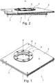
- a rotating device 1 comprises an eg plate-like superstructure 2, eg a plate-like substructure 3 and a rotary unit 4 according to the invention, the superstructure 2 being rotatably connected to the substructure 3 via the rotary unit 4 ( Figure 1 to 4 ).
- the superstructure 2 and the substructure 3 are produced, for example, in an extrusion process, for example, from aluminum.
- an extrusion process for example, from aluminum.
- the plate-like superstructure 2 and the plate-like substructure 3 e.g. Hollow chambers 5 introduced.
- An axis of rotation R of the rotary unit 4 is advantageously arranged perpendicular to the large flat top sides 6, 7 of the superstructure 2 and of the substructure 3 on the rotary device 1.
- the rotation axis R extends, for example, through a center of a passage opening 8 of the superstructure 2 and of the substructure 3.
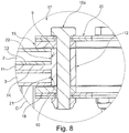
- the superstructure 2 and the substructure 3 have an inner edge 9, 10 (FIG. FIG. 8 ).
- the rotary unit 4 comprises a first sliding bearing 11, a second sliding bearing 18, a third sliding bearing 19 and a power transmission unit 17.
- the superstructure 2 and the substructure 3 are rotatably mounted, for example, by means of the plain bearings 11, 18, 19 of the rotary unit 4 about the rotation axis R ( FIGS. 1 . 4 . 5 . 7 . 8th ).
- the sliding bearing 11 is mounted between the superstructure 2 and the substructure 3.
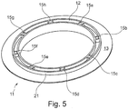
- the slide bearing 11 is advantageously designed annular and comprises in a radially inner region of a bead 12 which protrudes from a surface 13, 14 in particular opposite upwards and downwards.
- the sliding bearing 11 thus has a T-shaped cross-section ( FIG. 8 ).
- the sliding bearing 11 abuts with its radially outer bearing surface 21, 22 of the bead 12 to the inner edge 9 of the superstructure 2 and to the inner edge 10 of the substructure 3. As a result, it is fixed at its functional position on the rotating device 1.
- the surfaces 13, 14 of the sliding bearing 11 are formed as sliding bearing surfaces through which the superstructure 2 and the superstructure 3 are slidably mounted.
- connection openings 15a-15h are further introduced, through which connection elements of the power transmission unit 17 in the form of screws 16a-16h are plugged into the rotary unit 1 in the mounted state of the rotary unit 4. over nuts are countered.
- the sliding bearing 18 and the sliding bearing 19 are each arranged opposite to a sliding bearing surface 13, 14 of the sliding bearing 11 on an outer side of the superstructure 2 and the substructure 3.
- the superstructure 2 is slidably mounted to the sliding bearing 11 and the sliding bearing 19 and the base 3 is slidably mounted to the sliding bearing 11 and the sliding bearing 18.
- the second sliding bearing 18 and the third sliding bearing 19 are configured for example in the form of a flat ring. Viewed in cross-section ( FIG. 8 ) form the plain bearings 11, 18, 19 in the mounted state of the rotating device 1 thus, for example, a W-shape.
- the power transmission unit 17 comprises, in addition to the connecting elements, power transmission elements in the form of disk-like ring segments 20.
- the ring segments 20, the plain bearings 11, 18, 19, the superstructure 2 and the substructure 3 are clamped together by the screws 16a-16h, for example in a sandwich or packet shape ( FIGS. 6 to 8 ).
- the superstructure 2 is fixed relative to the substructure 3 in its functional position, on the other hand, by the force generated, advantageously parallel to the axis of rotation R, the screws 16a - 16h on the sliding bearing surfaces of the sliding bearings 11, 18, 19 and the sliding bearing surfaces of the superstructure 2 and the base 3, the friction effect or sliding action of the sliding bearing surfaces are adjusted to each other.
- the package consisting of ring segments 20, plain bearings 11, 18, 19, 2 and 3 substructure with each other be tense that in the mounted state in the vehicle during use or weight load by a user or by the body weight of a user twisting of the superstructure 2 is prevented relative to the base 3 due to the relatively high friction effect of the sliding bearing surfaces to each other.
Landscapes
- Engineering & Computer Science (AREA)
- Aviation & Aerospace Engineering (AREA)
- Transportation (AREA)
- Mechanical Engineering (AREA)
- Bridges Or Land Bridges (AREA)
- Seats For Vehicles (AREA)
- Vibration Prevention Devices (AREA)
Abstract
Description
- Die Erfindung betrifft eine Dreheinheit für eine Drehvorrichtung für einen Fahrzeugsitz, sowie eine Drehvorrichtung für einen Fahrzeugsitz mit einer Dreheinheit.
- Eine Dreheinheit für eine Drehvorrichtung für einen Fahrzeugsitz der einleitend bezeichneten Art ist in vielfältigen Ausführungsformen bereits bekannt.
- In Reisemobilen werden zum Beispiel Fahrzeugsitze eingesetzt, die sich drehen lassen, um den Fahrzeugsitz bei Stillstand des Fahrzeugs in einer anderen Position nutzen zu können.
- Eine bekannte Dreheinheit für eine Vorrichtung zum Drehen eines Fahrzeugsitzes umfasst zwei zueinander drehbar angeordnete Drehflansche, wobei ein unten liegender Drehflansch der Dreheinheit über eine Verschiebeplatte der Vorrichtung fest mit dem Fahrzeug verbunden ist und ein oben liegender Drehflansch mittels einer Verbindungsplatte der Vorrichtung fest mit dem Fahrzeugsitz verbunden ist. Durch die feste Verbindung der Drehflansche der Dreheinheit mit der Verschiebeplatte und der Verbindungsplatte der Drehvorrichtung wird eine vergleichsweise hohe Festigkeit der Drehvorrichtung erreicht.
- Der Erfindung liegt die Aufgabe zu Grunde, eine alternative und vergleichsweise kostengünstige Dreheinheit zur Verfügung zu stellen.
- Diese Aufgabe wird durch die Merkmale des Anspruchs 1 gelöst.
- In den abhängigen Ansprüchen sind vorteilhafte und zweckmäßige Ausführungsformen der Erfindung angegeben.
- Die Erfindung geht von einer Dreheinheit für eine Drehvorrichtung für einen Fahrzeugsitz aus, wobei die Drehvorrichtung einen Unterbau für ein Bodenteil zur Anbringung an einem Fahrzeugboden und einen Überbau, an welchem ein Sitz anbringbar ist, umfasst, wobei der Unterbau mit dem Überbau über die Dreheinheit verbindbar ist, wobei die Dreheinheit ein erstes Lagermittel umfasst.
- Die Drehvorrichtung ist insbesondere dazu vorgesehen den Fahrzeugsitz drehbar am Fahrzeugboden anzuordnen.
- Der wesentliche Aspekt der Erfindung ist nun darin zu sehen, dass das erste Lagermittel als Gleitlager ausgebildet ist und im montierten Zustand der Dreheinheit zwischen dem Überbau und dem Unterbau angeordnet ist, wobei der Überbau und der Unterbau im Bereich um eine Rotationsachse der Drehvorrichtung eine Durchgangsöffnung aufweisen, und dass das erste Lagermittel im angeordneten Zustand an der Drehvorrichtung in einer radialen Richtung, in Richtung der Rotationsachse der Drehvorrichtung über einen inneren Rand des Überbaus und des Unterbaus übersteht.
- Durch die vorteilhafte Ausgestaltung der Dreheinheit ist ein Zusammenbau der Drehvorrichtung erleichtert. Auch ist eine Produktion der Dreheinheit dadurch vergleichsweise kostengünstig.
- Mit überstehen ist z.B. gemeint, dass das Lagermittel in einer radialen Richtung, in Richtung der Rotationsachse der Drehvorrichtung, zwischen dem Überbau und dem Unterbau hervortritt und somit beispielsweise für einen Nutzer sichtbar ist. Zum Beispiel springt das Lagermittel im montierten Zustand an der Drehvorrichtung aus einer senkrechten Sicht von oben oder unten auf den Überbau bzw. den Unterbau gesehen im Bereich der Durchgangsöffnung zwischen dem Überbau und dem Unterbau hervor.
- Mit überstehen kann auch gemeint sein, dass das erste Lagermittel derart ausgebildet ist und im montierten Zustand an der Drehvorrichtung derart montiert ist, dass es den inneren Rand des Überbaus und/oder des Unterbaus zumindest teilweise überdeckt.
- Vorteilhafterweise ist das erste Lagermittel flach bzw. scheibenartig ausgebildet, insbesondere ist es ringartig ausgebildet. Das erste Lagermittel kann auch aus insbesondere flachen scheibenförmigen und/oder flachen ringförmigen Elementen bzw. Segmenten bestehen.
- Überdies ist es vorteilhaft, dass das erste Lagermittel als Gleitlager ausgebildet ist und im montierten Zustand der Dreheinheit zwischen dem Überbau und dem Unterbau angeordnet ist, und dass das erste Lagermittel ein Montageorgan umfasst, wobei das Montageorgan dazu ausgelegt ist, das erste Lagermittel mit dem Überbau und/oder dem Unterbau für eine radiale Positionierung des ersten Lagermittels zu verbinden.
- Durch die Ausbildung des ersten Lagermittels als Gleitlager ist das erste Lagermittel vergleichsweise einfach und/oder günstig herzustellen. Außerdem ist durch die Ausbildung des ersten Lagermittels die Drehvorrichtung vergleichsweise stabil ausgestaltet.
- Zum Beispiel sind im montierten Zustand der Drehvorrichtung die sich zugewandten Flächen des Überbaus und des Unterbaus über einen vergleichsweise großen Bereich durchgehend eben und flach ausgestaltet. Die Flächen können gegebenenfalls von Durchbrüchen bspw. für das Montageorgan unterbrochen sein. Bevorzugterweise sind die im montierten Zustand der Drehvorrichtung sich zugewandte Flächen des Überbaus und des Unterbaus parallel zueinander ausgerichtet.
- Der Überbau und/oder der Unterbau ist bevorzugterweise plattenförmig ausgestaltet, beispielsweise als vergleichsweise stabile Metallplatte.
- Vorteilhafterweise ist das Montageorgan derart ausgestaltet, dass im montierten Zustand der Dreheinheit der Überbau mit dem Unterbau beweglich verbindbar und/oder koppelbar ist. Der Überbau ist z.B. auf dem Unterbau lagerbar.
- Bevorzugterweise ist das erste Lagermittel durch das Montageorgan im montierten Zustand fest und unbeweglich mit dem Unterbau oder dem Überbau gekoppelt.
- Ein Montageorgan ist beispielsweise als Schlitz, Bohrung, insbesondere Durchgangsbohrung und/oder als abstehendes Element, beispielsweise als insbesondere umlaufender Wulst oder insbesondere umlaufende Lippe oder als abstehender Stift ausgebildet.
- Idealerweise umfasst der Unterbau und/oder der Überbau und/oder das Lagermittel eine Führungsbahn. Im montierten Zustand der Dreheinheit kann das Montageorgan des Lagerorgans derart in die Führungsbahn des Überbaus und/oder des Unterbaus eingreifen, sodass das Lagerorgan und/oder der Überbau und/oder der Unterbau ausschließlich zueinander drehbar geführt sind. Auch ist es bedeutsam, dass ein Montageelement des Überbaus und/oder des Unterbaus derart in die Führungsbahn des Lagermittels eingreifen kann, sodass das Lagermittel und/oder der Überbau und/oder der Unterbau ausschließlich zueinander drehbar geführt sind.
- Überdies von Vorteil ist, dass das erste Lagermittel in einem Querschnitt T-förmig ausgestaltet ist.
- Beispielsweise ist das Lagermittel in Form einer Unterlegscheibe ausgebildet und besitzt an einem radial innen liegenden Rand einen Wulst, so dass das erste Lagermittel in einem Querschnitt senkrecht zu einer Rotationsachse betrachtet in Form eines liegenden T's ausgestaltet ist.
- Durch eine derartige Ausbildung des ersten Lagermittels ist es möglich das erste Lagermittel im montierten Zustand an der Drehvorrichtung in einer Weise anzubringen, dass eine Bewegung senkrecht zu einer Rotationsachse der Drehvorrichtung blockiert ist. Insbesondere liegt das erste Lagermittel mit einer radial außen liegenden Seite des Wulstes am inneren Rand des Überbaus und/oder des Unterbaus an, hierdurch ist eine Bewegung des ersten Lagemittels in radialer bzw. horizontaler Richtung insbesondere senkrecht zur Rotationsachse insbesondere aus seiner Funktionsposition heraus unterbunden.
- In einer vorteilhaften Ausbildung der Erfindung weist die Dreheinheit mindestens ein weiteres, insbesondere zwei weitere Lagermittel auf, wobei das weitere Lagermittel derart ausgebildet ist, dass im montierten Zustand der Dreheinheit an der Drehvorrichtung der Überbau und/oder der Unterbau relativ zum weiteren Lagermittel bewegbar, insbesondere drehbar ist.
- Vorteilhafterweise ist das weitere Lagermittel flach, insbesondere scheibenartig bzw. ringförmig ausgestaltet. Beispielsweise kann das weitere Lagermittel scheibenartig und/oder ringförmig, zum Beispiel in Form einer Unterlegscheibe ausgebildet sein. Auch ist es vorstellbar, dass das weitere Lagermittel aus Segmenten besteht.
- Als elementar erweist sich auch, dass das weitere Lagermittel als Gleitlager ausgebildet ist.
- Weiter wird vorgeschlagen, dass die Lagermittel derart ausgestaltet sind, dass sie relativ zueinander bewegbar, insbesondere drehbar sind.
- Bevorzugterweise ist wenigstens das erste Lagermittel zu einem weiteren Lagermittel drehbar gelagert. Beispielsweise besitzt das erste Lagermittel zu einem weiteren Lagermittel eine Kontaktfläche, wobei das erste Lagermittel zu dem weiteren Lagermittel an der Kontaktfläche vergleichsweise reibungsfrei gelagert ist, so dass die beiden Lagermittel aufeinander gleiten können.
- Denkbar ist allerdings auch, dass die Lagermittel miteinander fest verbunden sind. Sind die Lagermittel miteinander fest verbunden, so ist z.B. zumindest das erste Lagermittel und ein weiteres Lagermittel beweglich mit dem Überbau oder dem Unterbau gekoppelt.
- In einer vorteilhaften Ausgestaltung der Erfindung ist ein Lagermittel in einem Querschnitt U-förmig ausgebildet. Denkbar ist auch, dass ein Lagermittel in einem Querschnitt W-förmig ausgebildet ist. Vorteilhafterweise ist das erste Lagermittel U-förmig oder W-förmig ausgestaltet.
- Durch die U-förmige oder W-förmige Ausgestaltung der Lagermittel kann die Anzahl der Lagermittel reduziert werden, hierdurch ist die Dreheinheit vergleichsweise kostengünstig ausgebildet.
- Ist ein Lagermittel U-förmig oder W-förmig ausgebildet, so ist der Überbau und/oder der Unterbau vorteilhafterweise 2-teilig ausgestaltet. Denkbar ist, dass der vorteilhaft plattenförmige Überbau und/oder der vorteilhaft plattenförmige Unterbau aus jeweils mindestens zwei plattenartigen, insbesondere gleichartigen Elementen besteht, wobei im zusammengesetzten Zustand der Drehvorrichtung der Überbau und/oder der Unterbau mit dem inneren Rand der Durchgangsöffnung voraus in die Aussparung des U's bzw. des W's eingeschoben oder eingesteckt sind. Hierdurch ist das erste Lagermittel in seiner Funktionsposition an der Drehvorrichtung festgelegt.
- Auch ist es von Vorteil, dass ein Lagermittel in einem Querschnitt L-förmig ausgebildet ist. Hierdurch kann insbesondere das erste Lagermittel im montierten Zustand an der Drehvorrichtung in seiner Funktionsposition gehalten sein.
- Weiter wird vorgeschlagen, dass die Lagermittel aus Kunststoff ausgebildet sind. Vorteilhafterweise besitzt der Kunststoff eine vergleichsweise reibungsarme Oberfläche mit niedrigem Reibungskoeffizient, insbesondere ist der Kunststoff Polyoxymethylen (POM). Denkbar ist auch, dass die Lagermittel einen vergleichsweise stabilen Metallkern enthalten, z.B. einen Stahlkern, welcher bspw. von Kunststoff umschlossen ist.
- Auch ist es von Vorteil, dass die Dreheinheit eine Kraftübertragungseinheit aufweist, wobei die Kraftübertragungseinheit dazu vorgesehen ist, im montierten Zustand der Dreheinheit an der Drehvorrichtung die Lagermittel zu verspannen, wobei der Überbau und der Unterbau darin eingelegt sind. Die Kraftübertragungseinheit ist beispielsweise als Klammer ausgestaltet.
- Des Weiteren ist es wesentlich, dass die Kraftübertragungseinheit ein Kraftübertragungselement umfasst, und das Kraftübertragungselement plattenförmig ausgebildet ist.
- Bevorzugterweise ist ein Kraftübertragungselement als flaches, plattenartiges und aus einer Aufsicht vorteilhaft bananenförmiges oder kreisförmiges Element, beispielsweise in Form eines Teilkreises bzw. Segments, ausgeformt. Beispielsweise ist das Kraftübertragungselement eine Metallplatte. Denkbar ist auch, dass das Kraftübertragungselement in Form einer Unterlegscheibe ausgebildet ist. Insbesondere ist das Kraftübertragungselement aus einem vergleichsweise stabilen Material ausgebildet, z.B. aus Metall.
- Weiter wird vorgeschlagen, dass die Kraftübertragungseinheit ein Verbindungselement umfasst, wobei das Verbindungselement dazu vorgesehen ist, im montierten Zustand der Dreheinheit an der Drehvorrichtung die Lagermittel kraftschlüssig zu verbinden. Vorteilhafterweise ist im montierten Zustand der Drehvorrichtung der Überbau mit dem Unterbau durch das Verbindungselement verspannbar, insbesondere über die Lagermittel. Das Verbindungselement kann beispielsweise als Bolzen und/oder Stift und/oder Schraube ausgestaltet sein.
- In einer vorteilhaften Ausgestaltung der Erfindung ist der Überbau und/oder der Unterbau der Drehvorrichtung plattenförmig ausgestaltet, wobei der Überbau und/oder der Unterbau Hohlkammern umfasst. Durch die Ausgestaltung des Überbaus und/oder des Unterbaus als Hohlkammerplatte, wobei die Platte Kammern bzw. Waben und/oder Poren umfasst, ist eine vergleichsweise hohe Stabilität, insbesondere hinsichtlich auftretender Torsionskräfte, erzielbar. Insbesondere ist durch die Ausgestaltung des Überbaus und/oder des Unterbaus als Hohlkammerplatte eine Gewichtsreduktion der Drehvorrichtung erreicht. Vorstellbar ist weiter, dass der Überbau und/oder der Unterbau der Drehvorrichtung zumindest zu einem überwiegenden Teil aus einem Metallschaum hergestellt ist.
- Insbesondere ist der Überbau und/oder der Unterbau aus einem Strangpress-Profil hergestellt. Vorteilhafterweise ist der Überbau und/oder der Unterbau aus Aluminium oder Kunststoff ausgebildet.
- Ein Ausführungsbeispiel wird anhand der nachstehenden schematischen Zeichnungen unter Angabe weiterer Einzelheiten und Vorteile näher erläutert:
- Es zeigen:
- Figur 1
- eine perspektivische Ansicht von schräg oben auf eine Drehvorrichtung mit einer erfindungsgemäßen Dreheinheit,
- Figur 2
- eine perspektivische Ansicht von schräg oben und vorne auf die Drehvorrichtung nach
Figur 1 , wobei der Überbau zum Unterbau verdreht dargestellt ist, - Figur 3
- eine seitliche Ansicht auf die linke Seite der Drehvorrichtung nach
Figur 1 , - Figur 4
- eine Ansicht von Vorne auf die Drehvorrichtung nach
Figur 1 , - Figur 5
- eine perspektivische Ansicht von schräg oben auf ein erstes Lagermittel der Dreheinheit,
- Figur 6
- eine Draufsicht auf die Drehvorrichtung nach
Figur 1 , - Figur 7
- eine seitliche Ansicht auf einen Schnitt nach
Figur 6 durch die Drehvorrichtung nachFigur 1 und - Figur 8
- eine Detailansicht des Schnitts nach
Figur 7 durch die Drehvorrichtung nachFigur 1 .
- Eine Drehvorrichtung 1 umfasst einen z.B. plattenartigen Überbau 2, einen z.B. plattenartigen Unterbau 3 und eine erfindungsgemäße Dreheinheit 4, wobei der Überbau 2 mit dem Unterbau 3 über die Dreheinheit 4 drehbar verbunden ist (
Figur 1 bis 4 ). - Der Überbau 2 und der Unterbau 3 ist zum Beispiel in einem Strangpress-Verfahren bspw. aus Aluminium hergestellt. Durch das Strangpress-Verfahren sind in den plattenartigen Überbau 2 und den plattenartigen Unterbau 3 z.B. Hohlkammern 5 eingebracht.
- Eine Rotationsachse R der Dreheinheit 4 ist vorteilhaft senkrecht zu den großen flachen Oberseiten 6, 7 des Überbaus 2 und des Unterbaus 3 an der Drehvorrichtung 1 angeordnet. Die Rotationsachse R verläuft beispielsweise durch ein Zentrum einer Durchgangsöffnung 8 des Überbaus 2 und des Unterbaus 3. An der radial innen liegenden Seite der Durchgangsöffnung 8 besitzen der Überbau 2 und der Unterbau 3 einen inneren Rand 9, 10 (
Figur 8 ). - Die Dreheinheit 4 umfasst ein erstes Gleitlager 11, ein zweites Gleitlager 18, ein drittes Gleitlager 19 und eine Kraftübertragungseinheit 17.
- Der Überbau 2 und der Unterbau 3 sind z.B. mittels der Gleitlager 11, 18 ,19 der Dreheinheit 4 um die Rotationsachse R drehbar gelagert (
Figuren 1 ,4 ,5 ,7 ,8 ). Dabei ist das Gleitlager 11 zwischen dem Überbau 2 und dem Unterbau 3 montiert. - Das Gleitlager 11 ist vorteilhaft ringförmig ausgestaltet und umfasst in einem radial innen liegenden Bereich einen Wulst 12, welcher aus einer Oberfläche 13, 14 insbesondere gegenüberliegend nach oben und nach unten hervorsteht. Das Gleitlager 11 besitzt somit einen T-förmigen Querschnitt (
Figur 8 ). Im zusammengebauten Zustand der Drehvorrichtung 1 stößt das Gleitlager 11 mit seinen radial außen liegenden Anlagefläche 21, 22 des Wulsts 12 an den inneren Rand 9 des Überbaus 2 und an den inneren Rand 10 des Unterbaus 3 an. Hierdurch ist es an seiner Funktionsposition an der Drehvorrichtung 1 festgelegt. - Die Oberflächen 13, 14 des Gleitlagers 11 sind als Gleitlagerflächen ausgebildet, durch welche der Überbau 2 und der Überbau 3 gleitend gelagert sind. Im Wulst 12 sind weiterhin Verbindungsöffnungen 15a - 15h eingebracht, durch welche im montierten Zustand der Dreheinheit 4 an der Drehvorrichtung 1 Verbindungselemente der Kraftübertragungseinheit 17 in Form von Schrauben 16a - 16h eingesteckt sind, welche z.B. über Muttern gekontert sind.
- Das Gleitlager 18 und das Gleitlager 19 ist jeweils gegenüberliegend zu einer Gleitlagerfläche 13, 14 des Gleitlagers 11 an einer Außenseite des Überbaus 2 bzw. des Unterbaus 3 angeordnet. Hierdurch ist der Überbau 2 gleitend zum Gleitlager 11 und zum Gleitlager 19 gelagert und der Unterbau 3 ist gleitend zum Gleitlager 11 und zum Gleitlager 18 gelagert. Das zweite Gleitlager 18 und das dritte Gleitlager 19 sind z.B. in Form eines flachen Rings ausgestaltet. Im Querschnitt betrachtet (
Figur 8 ) bilden die Gleitlager 11, 18, 19 im montierten Zustand an der Drehvorrichtung 1 somit z.B. eine W-Form aus. - Die Kraftübertragungseinheit 17 umfasst, neben den Verbindungselementen Kraftübertragungselemente in Form von scheibenartigen Ringsegmenten 20. Die Ringsegmente 20, die Gleitlager 11, 18, 19, der Überbau 2 und der Unterbau 3 sind durch die Schrauben 16a - 16h beispielsweise sandwichartig oder paketartig miteinander verspannt (
Figuren 6 bis 8 ). Zum einen ist hierdurch der Überbau 2 relativ zum Unterbau 3 in seiner Funktionsposition festgelegt, zum anderen kann durch die erzeugte Kraft, vorteilhaft parallel zur Rotationsachse R, der Schrauben 16a - 16h auf die Gleitlagerflächen der Gleitlager 11, 18, 19 und die Gleitlagerflächen des Überbaus 2 und des Unterbaus 3 die Reibwirkung bzw. Gleitwirkung der Gleitlagerflächen zueinander eingestellt werden. - Beispielsweise kann das Paket bestehend aus Ringssegmenten 20, Gleitlager 11, 18, 19, 2 und Unterbau 3 derart miteinander verspannt werden, dass im montierten Zustand im Fahrzeug bei Benutzung bzw. Gewichtsbelastung durch einen Nutzer bzw. durch das Körpergewicht eines Nutzers ein Verdrehen des Überbaus 2 relativ zum Unterbau 3 aufgrund der vergleichsweise hohen Reibwirkung der Gleitlagerflächen zueinander unterbunden ist.
-
- 1
- Drehvorrichtung
- 2
- Überbau
- 3
- Unterbau
- 4
- Dreheinheit
- 5
- Hohlkammern
- 6 - 7
- Oberseite
- 8
- Durchgangsöffnung
- 9 - 10
- Rand
- 11
- Gleitlager
- 12
- Wulst
- 13 - 14
- Oberfläche
- 15a - 15h
- Verbindungsöffnung
- 16a - 16h
- Schraube
- 17
- Kraftübertragungseinheit
- 18 - 19
- Gleitlager
- 20
- Ringsegment
- 21
- Anlagefläche
- 22
- Anlagefläche
Claims (13)
- Dreheinheit (4) für eine Drehvorrichtung (1) für einen Fahrzeugsitz, wobei die Drehvorrichtung (1) einen Unterbau (3) für ein Bodenteil zur Anbringung an einem Fahrzeugboden und einen Überbau (2), an welchem ein Sitz anbringbar ist, umfasst, wobei der Unterbau (3) mit dem Überbau über die Dreheinheit (4) verbindbar ist, wobei die Dreheinheit (4) ein erstes Lagermittel umfasst, dadurch gekennzeichnet, dass das erste Lagermittel als Gleitlager (11) ausgebildet ist und im montierten Zustand der Dreheinheit (4) zwischen dem Überbau (2) und dem Unterbau (3) angeordnet ist, wobei der Überbau (2) und der Unterbau (3) im Bereich um eine Rotationsachse R der Drehvorrichtung (1) eine Durchgangsöffnung (8) aufweisen, und wobei das erste Lagermittel (11) im angeordneten Zustand an der Drehvorrichtung (1) in einer radialen Richtung, in Richtung der Rotationsachse R der Drehvorrichtung (1) über einen inneren Rand (9, 10) des Überbaus (2) und des Unterbaus (3) übersteht.
- Dreheinheit (4) für eine Drehvorrichtung (1) nach dem Oberbegriff des Anspruchs 1, insbesondere nach Anspruch 1, dadurch gekennzeichnet, dass das erste Lagermittel als Gleitlager (11) ausgebildet ist und im montierten Zustand der Dreheinheit (4) zwischen dem Überbau (2) und dem Unterbau (3) angeordnet ist, und dass das erste Lagermittel (11) ein Montageorgan (12) umfasst, wobei das Montageorgan dazu ausgelegt ist, das erste Lagermittel mit dem Überbau (2) und/oder dem Unterbau (3) für eine radiale Positionierung des ersten Lagermittels (11) zu verbinden.
- Dreheinheit (4) für eine Drehvorrichtung (1) nach einem der vorangegangenen Ansprüche, dadurch gekennzeichnet, dass das erste Lagermittel (11) in einem Querschnitt T-förmig ausgestaltet ist.
- Dreheinheit (4) für eine Drehvorrichtung (1) nach einem der vorangegangenen Ansprüche, dadurch gekennzeichnet, dass die Dreheinheit (4) mindestens ein weiteres, insbesondere zwei weitere Lagermittel (18, 19) aufweist, wobei das weitere Lagermittel (18, 19) derart ausgebildet ist, dass im montierten Zustand der Dreheinheit (4) an der Drehvorrichtung (1) der Überbau (2) und/oder der Unterbau (3) relativ zum weiteren Lagermittel (18, 19) bewegbar, insbesondere drehbar ist.
- Dreheinheit (4) für eine Drehvorrichtung (1) nach einem der vorangegangenen Ansprüche, dadurch gekennzeichnet, dass die Lagermittel (11, 18, 19) derart ausgestaltet sind, dass sie relativ zueinander bewegbar, insbesondere drehbar sind.
- Dreheinheit (4) für eine Drehvorrichtung (1) nach einem der vorangegangenen Ansprüche, dadurch gekennzeichnet, dass ein Lagermittel (11, 18, 19) in einem Querschnitt U-förmig ausgebildet ist.
- Dreheinheit (4) für eine Drehvorrichtung (1) nach einem der vorangegangenen Ansprüche, dadurch gekennzeichnet, dass ein Lagermittel (11, 18, 19) in einem Querschnitt L-förmig ausgebildet ist.
- Dreheinheit (4) für eine Drehvorrichtung (1) nach einem der vorangegangenen Ansprüche, dadurch gekennzeichnet, dass die Lagermittel (11, 18, 19) aus Kunststoff ausgebildet sind.
- Dreheinheit (4) für eine Drehvorrichtung (1) nach einem der vorangegangenen Ansprüche, dadurch gekennzeichnet, dass die Dreheinheit (4) eine Kraftübertragungseinheit (17) aufweist, wobei die Kraftübertragungseinheit (17) dazu vorgesehen ist, im montierten Zustand der Dreheinheit (4) an der Drehvorrichtung (1) die Lagermittel (11, 18, 19) zu verspannen, wobei der Überbau (2) und der Unterbau (3) darin eingelegt sind.
- Dreheinheit (4) für eine Drehvorrichtung (1) nach einem der vorangegangenen Ansprüche, dadurch gekennzeichnet, dass die Kraftübertragungseinheit (17) ein Kraftübertragungselement (20) umfasst, und das Kraftübertragungselement (20) plattenförmig ausgebildet ist.
- Dreheinheit (4) für eine Drehvorrichtung (1) nach einem der vorangegangenen Ansprüche, dadurch gekennzeichnet, dass die Kraftübertragungseinheit (17) ein Verbindungselement (16a - 16h) umfasst, wobei das Verbindungselement (16a - 16h) dazu vorgesehen ist, im montierten Zustand der Dreheinheit (4) an der Drehvorrichtung (1) die Lagermittel (11, 18, 19) kraftschlüssig zu verbinden.
- Drehvorrichtung (1) mit einer Dreheinheit (4) nach einem der vorangegangenen Ansprüche.
- Drehvorrichtung (1) nach Anspruch 12, dadurch gekennzeichnet, dass der Überbau (2) und/oder der Unterbau (3) plattenförmig ausgestaltet ist und der Überbau (2) und/oder der Unterbau (3) Hohlkammern (5) umfasst.
Priority Applications (1)
| Application Number | Priority Date | Filing Date | Title |
|---|---|---|---|
| SI201630600T SI3205531T1 (sl) | 2016-02-12 | 2016-12-13 | Vrtljiva enota za vrtljivo napravo za sedež vozila |
Applications Claiming Priority (1)
| Application Number | Priority Date | Filing Date | Title |
|---|---|---|---|
| DE102016102451.1A DE102016102451A1 (de) | 2016-02-12 | 2016-02-12 | Dreheinheit für eine Drehvorrichtung für einen Fahrzeugsitz |
Publications (2)
| Publication Number | Publication Date |
|---|---|
| EP3205531A1 true EP3205531A1 (de) | 2017-08-16 |
| EP3205531B1 EP3205531B1 (de) | 2019-12-11 |
Family
ID=57544327
Family Applications (1)
| Application Number | Title | Priority Date | Filing Date |
|---|---|---|---|
| EP16203657.8A Active EP3205531B1 (de) | 2016-02-12 | 2016-12-13 | Dreheinheit für eine drehvorrichtung für einen fahrzeugsitz |
Country Status (4)
| Country | Link |
|---|---|
| EP (1) | EP3205531B1 (de) |
| DE (1) | DE102016102451A1 (de) |
| ES (1) | ES2772425T3 (de) |
| SI (1) | SI3205531T1 (de) |
Cited By (2)
| Publication number | Priority date | Publication date | Assignee | Title |
|---|---|---|---|---|
| CN110626229A (zh) * | 2019-10-31 | 2019-12-31 | 湖北航嘉麦格纳座椅系统有限公司 | 汽车座椅及座椅旋转机构 |
| FR3144950A1 (fr) * | 2023-01-12 | 2024-07-19 | Scopema | Embase pivotante pour un siège de véhicule, notamment de véhicule automobile, siège et véhicule automobile associés |
Citations (5)
| Publication number | Priority date | Publication date | Assignee | Title |
|---|---|---|---|---|
| DE69529396T2 (de) * | 1995-01-03 | 2003-05-15 | The Boeing Co., Seattle | Transfer-Giessverfahren in Kombination mit wabenförmigen Kern |
| DE10163736A1 (de) * | 2001-12-21 | 2003-07-03 | Richard Kaepplinger | Drehkonsole für Fahrzeugsitz |
| DE202011051401U1 (de) * | 2011-07-18 | 2011-11-17 | Ford-Werke Gmbh | Ladeboden |
| WO2012116785A1 (de) * | 2011-03-01 | 2012-09-07 | Keiper Gmbh & Co. Kg | Fahrzeugsitz |
| DE102011055010B4 (de) * | 2010-11-05 | 2015-08-06 | Westfalia Presstechnik Gmbh & Co. Kg | Hybridbauteil für den Fahrzeugbereich |
-
2016
- 2016-02-12 DE DE102016102451.1A patent/DE102016102451A1/de not_active Withdrawn
- 2016-12-13 ES ES16203657T patent/ES2772425T3/es active Active
- 2016-12-13 SI SI201630600T patent/SI3205531T1/sl unknown
- 2016-12-13 EP EP16203657.8A patent/EP3205531B1/de active Active
Patent Citations (5)
| Publication number | Priority date | Publication date | Assignee | Title |
|---|---|---|---|---|
| DE69529396T2 (de) * | 1995-01-03 | 2003-05-15 | The Boeing Co., Seattle | Transfer-Giessverfahren in Kombination mit wabenförmigen Kern |
| DE10163736A1 (de) * | 2001-12-21 | 2003-07-03 | Richard Kaepplinger | Drehkonsole für Fahrzeugsitz |
| DE102011055010B4 (de) * | 2010-11-05 | 2015-08-06 | Westfalia Presstechnik Gmbh & Co. Kg | Hybridbauteil für den Fahrzeugbereich |
| WO2012116785A1 (de) * | 2011-03-01 | 2012-09-07 | Keiper Gmbh & Co. Kg | Fahrzeugsitz |
| DE202011051401U1 (de) * | 2011-07-18 | 2011-11-17 | Ford-Werke Gmbh | Ladeboden |
Cited By (2)
| Publication number | Priority date | Publication date | Assignee | Title |
|---|---|---|---|---|
| CN110626229A (zh) * | 2019-10-31 | 2019-12-31 | 湖北航嘉麦格纳座椅系统有限公司 | 汽车座椅及座椅旋转机构 |
| FR3144950A1 (fr) * | 2023-01-12 | 2024-07-19 | Scopema | Embase pivotante pour un siège de véhicule, notamment de véhicule automobile, siège et véhicule automobile associés |
Also Published As
| Publication number | Publication date |
|---|---|
| ES2772425T3 (es) | 2020-07-07 |
| EP3205531B1 (de) | 2019-12-11 |
| SI3205531T1 (sl) | 2020-04-30 |
| DE102016102451A1 (de) | 2017-08-17 |
Similar Documents
| Publication | Publication Date | Title |
|---|---|---|
| DE102011108976B4 (de) | Verfahren zur Herstellung einer Lageranordnung und Beschlag für einen Fahrzeugsitz mit einer hiernach hergestellten Lageranordnung | |
| DE102012012847B3 (de) | Beschlag für einen Fahrzeugsitz und Fahrzeugsitz | |
| DE102016007870A1 (de) | Sitzgestell für eine höhenverstellbare und neigbare Sitzteilwanne | |
| DE102009040504A1 (de) | Beschlag für einen Fahrzeugsitz | |
| DE2539023A1 (de) | Einstellmechanismus fuer sitze | |
| DE112008001431T5 (de) | Beschlag für einen Fahrzeugsitz | |
| DE202009015235U1 (de) | Fahrzeugsitz, insbesondere Kraftfahrzeugsitz | |
| DE102011106285A1 (de) | Beschlagsystem für einen Fahrzeugsitz | |
| EP2983943A1 (de) | Längseinsteller für einen fahrzeugsitz und fahrzeugsitz | |
| DE102004010491B4 (de) | Beschlag für einen Fahrzeugsitz | |
| EP3205531B1 (de) | Dreheinheit für eine drehvorrichtung für einen fahrzeugsitz | |
| EP3057825B1 (de) | Drehvorrichtung für einen fahrzeugsitz und fahrzeugsitz | |
| EP0995371B1 (de) | Bürostuhl mit einer Sitzneigungsverstellung | |
| DE10316190A1 (de) | Klemmvorrichtung zur Lagefixierung einer Lenksäule | |
| DE102008036647A1 (de) | Taumelgelenkbeschlag für einen Kraftfahrzeugsitz | |
| DE102010054314B4 (de) | Beschlagsystem für einen Fahrzeugsitz | |
| DE102010051497B4 (de) | Fahrzeugsitz, insbesondere Kraftfahrzeugsitz | |
| DE102010032507B4 (de) | Lineareinsteller für einen Fahrzeugsitz | |
| DE102017128322A1 (de) | Winkelverstellbare Konsole | |
| WO2021047921A2 (de) | Dreheinheit für einen um seine hochachse rotierbaren fahrzeugsitz, crashhaken für eine solche dreheinheit und rotierbarer fahrzeugsitz | |
| DE102004044753B4 (de) | Neigungsverstellbeschlag für die Rückenlehne eines Kraftfahrzeugsitzes | |
| DE202014105198U1 (de) | Auflagerelement einer Unterfederung eines Sitz- oder Liegemöbels | |
| DE102015215367B4 (de) | Beschlagsystem für einen Fahrzeugsitz sowie Fahrzeugsitz | |
| DE102004039538A1 (de) | Verstellvorrichtung für eine Fahrzeugkomponente, insbesondere für einen Kraftfahrzeugsitz | |
| DE202014100687U1 (de) | Als Wendescharnier ausgebildetes Kraftfahrzeugtürscharnier |
Legal Events
| Date | Code | Title | Description |
|---|---|---|---|
| PUAI | Public reference made under article 153(3) epc to a published international application that has entered the european phase |
Free format text: ORIGINAL CODE: 0009012 |
|
| STAA | Information on the status of an ep patent application or granted ep patent |
Free format text: STATUS: THE APPLICATION HAS BEEN PUBLISHED |
|
| AK | Designated contracting states |
Kind code of ref document: A1 Designated state(s): AL AT BE BG CH CY CZ DE DK EE ES FI FR GB GR HR HU IE IS IT LI LT LU LV MC MK MT NL NO PL PT RO RS SE SI SK SM TR |
|
| AX | Request for extension of the european patent |
Extension state: BA ME |
|
| STAA | Information on the status of an ep patent application or granted ep patent |
Free format text: STATUS: REQUEST FOR EXAMINATION WAS MADE |
|
| 17P | Request for examination filed |
Effective date: 20171211 |
|
| RBV | Designated contracting states (corrected) |
Designated state(s): AL AT BE BG CH CY CZ DE DK EE ES FI FR GB GR HR HU IE IS IT LI LT LU LV MC MK MT NL NO PL PT RO RS SE SI SK SM TR |
|
| STAA | Information on the status of an ep patent application or granted ep patent |
Free format text: STATUS: EXAMINATION IS IN PROGRESS |
|
| 17Q | First examination report despatched |
Effective date: 20181211 |
|
| GRAP | Despatch of communication of intention to grant a patent |
Free format text: ORIGINAL CODE: EPIDOSNIGR1 |
|
| STAA | Information on the status of an ep patent application or granted ep patent |
Free format text: STATUS: GRANT OF PATENT IS INTENDED |
|
| INTG | Intention to grant announced |
Effective date: 20190712 |
|
| GRAS | Grant fee paid |
Free format text: ORIGINAL CODE: EPIDOSNIGR3 |
|
| GRAA | (expected) grant |
Free format text: ORIGINAL CODE: 0009210 |
|
| STAA | Information on the status of an ep patent application or granted ep patent |
Free format text: STATUS: THE PATENT HAS BEEN GRANTED |
|
| AK | Designated contracting states |
Kind code of ref document: B1 Designated state(s): AL AT BE BG CH CY CZ DE DK EE ES FI FR GB GR HR HU IE IS IT LI LT LU LV MC MK MT NL NO PL PT RO RS SE SI SK SM TR |
|
| REG | Reference to a national code |
Ref country code: GB Ref legal event code: FG4D Free format text: NOT ENGLISH |
|
| REG | Reference to a national code |
Ref country code: CH Ref legal event code: EP |
|
| REG | Reference to a national code |
Ref country code: AT Ref legal event code: REF Ref document number: 1211857 Country of ref document: AT Kind code of ref document: T Effective date: 20191215 |
|
| REG | Reference to a national code |
Ref country code: DE Ref legal event code: R096 Ref document number: 502016007961 Country of ref document: DE |
|
| REG | Reference to a national code |
Ref country code: IE Ref legal event code: FG4D Free format text: LANGUAGE OF EP DOCUMENT: GERMAN |
|
| REG | Reference to a national code |
Ref country code: NL Ref legal event code: MP Effective date: 20191211 |
|
| REG | Reference to a national code |
Ref country code: LT Ref legal event code: MG4D |
|
| PG25 | Lapsed in a contracting state [announced via postgrant information from national office to epo] |
Ref country code: GR Free format text: LAPSE BECAUSE OF FAILURE TO SUBMIT A TRANSLATION OF THE DESCRIPTION OR TO PAY THE FEE WITHIN THE PRESCRIBED TIME-LIMIT Effective date: 20200312 Ref country code: LT Free format text: LAPSE BECAUSE OF FAILURE TO SUBMIT A TRANSLATION OF THE DESCRIPTION OR TO PAY THE FEE WITHIN THE PRESCRIBED TIME-LIMIT Effective date: 20191211 Ref country code: BG Free format text: LAPSE BECAUSE OF FAILURE TO SUBMIT A TRANSLATION OF THE DESCRIPTION OR TO PAY THE FEE WITHIN THE PRESCRIBED TIME-LIMIT Effective date: 20200311 Ref country code: NO Free format text: LAPSE BECAUSE OF FAILURE TO SUBMIT A TRANSLATION OF THE DESCRIPTION OR TO PAY THE FEE WITHIN THE PRESCRIBED TIME-LIMIT Effective date: 20200311 Ref country code: SE Free format text: LAPSE BECAUSE OF FAILURE TO SUBMIT A TRANSLATION OF THE DESCRIPTION OR TO PAY THE FEE WITHIN THE PRESCRIBED TIME-LIMIT Effective date: 20191211 Ref country code: LV Free format text: LAPSE BECAUSE OF FAILURE TO SUBMIT A TRANSLATION OF THE DESCRIPTION OR TO PAY THE FEE WITHIN THE PRESCRIBED TIME-LIMIT Effective date: 20191211 Ref country code: FI Free format text: LAPSE BECAUSE OF FAILURE TO SUBMIT A TRANSLATION OF THE DESCRIPTION OR TO PAY THE FEE WITHIN THE PRESCRIBED TIME-LIMIT Effective date: 20191211 |
|
| PG25 | Lapsed in a contracting state [announced via postgrant information from national office to epo] |
Ref country code: RS Free format text: LAPSE BECAUSE OF FAILURE TO SUBMIT A TRANSLATION OF THE DESCRIPTION OR TO PAY THE FEE WITHIN THE PRESCRIBED TIME-LIMIT Effective date: 20191211 Ref country code: HR Free format text: LAPSE BECAUSE OF FAILURE TO SUBMIT A TRANSLATION OF THE DESCRIPTION OR TO PAY THE FEE WITHIN THE PRESCRIBED TIME-LIMIT Effective date: 20191211 |
|
| PG25 | Lapsed in a contracting state [announced via postgrant information from national office to epo] |
Ref country code: AL Free format text: LAPSE BECAUSE OF FAILURE TO SUBMIT A TRANSLATION OF THE DESCRIPTION OR TO PAY THE FEE WITHIN THE PRESCRIBED TIME-LIMIT Effective date: 20191211 |
|
| REG | Reference to a national code |
Ref country code: ES Ref legal event code: FG2A Ref document number: 2772425 Country of ref document: ES Kind code of ref document: T3 Effective date: 20200707 |
|
| PG25 | Lapsed in a contracting state [announced via postgrant information from national office to epo] |
Ref country code: PT Free format text: LAPSE BECAUSE OF FAILURE TO SUBMIT A TRANSLATION OF THE DESCRIPTION OR TO PAY THE FEE WITHIN THE PRESCRIBED TIME-LIMIT Effective date: 20200506 Ref country code: EE Free format text: LAPSE BECAUSE OF FAILURE TO SUBMIT A TRANSLATION OF THE DESCRIPTION OR TO PAY THE FEE WITHIN THE PRESCRIBED TIME-LIMIT Effective date: 20191211 Ref country code: NL Free format text: LAPSE BECAUSE OF FAILURE TO SUBMIT A TRANSLATION OF THE DESCRIPTION OR TO PAY THE FEE WITHIN THE PRESCRIBED TIME-LIMIT Effective date: 20191211 Ref country code: CZ Free format text: LAPSE BECAUSE OF FAILURE TO SUBMIT A TRANSLATION OF THE DESCRIPTION OR TO PAY THE FEE WITHIN THE PRESCRIBED TIME-LIMIT Effective date: 20191211 Ref country code: RO Free format text: LAPSE BECAUSE OF FAILURE TO SUBMIT A TRANSLATION OF THE DESCRIPTION OR TO PAY THE FEE WITHIN THE PRESCRIBED TIME-LIMIT Effective date: 20191211 |
|
| REG | Reference to a national code |
Ref country code: CH Ref legal event code: PL |
|
| REG | Reference to a national code |
Ref country code: BE Ref legal event code: MM Effective date: 20191231 |
|
| PG25 | Lapsed in a contracting state [announced via postgrant information from national office to epo] |
Ref country code: IS Free format text: LAPSE BECAUSE OF FAILURE TO SUBMIT A TRANSLATION OF THE DESCRIPTION OR TO PAY THE FEE WITHIN THE PRESCRIBED TIME-LIMIT Effective date: 20200411 Ref country code: SK Free format text: LAPSE BECAUSE OF FAILURE TO SUBMIT A TRANSLATION OF THE DESCRIPTION OR TO PAY THE FEE WITHIN THE PRESCRIBED TIME-LIMIT Effective date: 20191211 Ref country code: SM Free format text: LAPSE BECAUSE OF FAILURE TO SUBMIT A TRANSLATION OF THE DESCRIPTION OR TO PAY THE FEE WITHIN THE PRESCRIBED TIME-LIMIT Effective date: 20191211 |
|
| REG | Reference to a national code |
Ref country code: DE Ref legal event code: R097 Ref document number: 502016007961 Country of ref document: DE |
|
| PG25 | Lapsed in a contracting state [announced via postgrant information from national office to epo] |
Ref country code: MC Free format text: LAPSE BECAUSE OF FAILURE TO SUBMIT A TRANSLATION OF THE DESCRIPTION OR TO PAY THE FEE WITHIN THE PRESCRIBED TIME-LIMIT Effective date: 20191211 |
|
| PLBE | No opposition filed within time limit |
Free format text: ORIGINAL CODE: 0009261 |
|
| STAA | Information on the status of an ep patent application or granted ep patent |
Free format text: STATUS: NO OPPOSITION FILED WITHIN TIME LIMIT |
|
| PG25 | Lapsed in a contracting state [announced via postgrant information from national office to epo] |
Ref country code: LU Free format text: LAPSE BECAUSE OF NON-PAYMENT OF DUE FEES Effective date: 20191213 Ref country code: DK Free format text: LAPSE BECAUSE OF FAILURE TO SUBMIT A TRANSLATION OF THE DESCRIPTION OR TO PAY THE FEE WITHIN THE PRESCRIBED TIME-LIMIT Effective date: 20191211 Ref country code: IE Free format text: LAPSE BECAUSE OF NON-PAYMENT OF DUE FEES Effective date: 20191213 |
|
| 26N | No opposition filed |
Effective date: 20200914 |
|
| PG25 | Lapsed in a contracting state [announced via postgrant information from national office to epo] |
Ref country code: CH Free format text: LAPSE BECAUSE OF NON-PAYMENT OF DUE FEES Effective date: 20191231 Ref country code: BE Free format text: LAPSE BECAUSE OF NON-PAYMENT OF DUE FEES Effective date: 20191231 Ref country code: LI Free format text: LAPSE BECAUSE OF NON-PAYMENT OF DUE FEES Effective date: 20191231 |
|
| PGFP | Annual fee paid to national office [announced via postgrant information from national office to epo] |
Ref country code: GB Payment date: 20201223 Year of fee payment: 5 |
|
| PG25 | Lapsed in a contracting state [announced via postgrant information from national office to epo] |
Ref country code: PL Free format text: LAPSE BECAUSE OF FAILURE TO SUBMIT A TRANSLATION OF THE DESCRIPTION OR TO PAY THE FEE WITHIN THE PRESCRIBED TIME-LIMIT Effective date: 20191211 |
|
| PGFP | Annual fee paid to national office [announced via postgrant information from national office to epo] |
Ref country code: SI Payment date: 20201203 Year of fee payment: 5 |
|
| PG25 | Lapsed in a contracting state [announced via postgrant information from national office to epo] |
Ref country code: CY Free format text: LAPSE BECAUSE OF FAILURE TO SUBMIT A TRANSLATION OF THE DESCRIPTION OR TO PAY THE FEE WITHIN THE PRESCRIBED TIME-LIMIT Effective date: 20191211 |
|
| PGFP | Annual fee paid to national office [announced via postgrant information from national office to epo] |
Ref country code: ES Payment date: 20210223 Year of fee payment: 5 |
|
| PG25 | Lapsed in a contracting state [announced via postgrant information from national office to epo] |
Ref country code: HU Free format text: LAPSE BECAUSE OF FAILURE TO SUBMIT A TRANSLATION OF THE DESCRIPTION OR TO PAY THE FEE WITHIN THE PRESCRIBED TIME-LIMIT; INVALID AB INITIO Effective date: 20161213 Ref country code: MT Free format text: LAPSE BECAUSE OF FAILURE TO SUBMIT A TRANSLATION OF THE DESCRIPTION OR TO PAY THE FEE WITHIN THE PRESCRIBED TIME-LIMIT Effective date: 20191211 |
|
| PG25 | Lapsed in a contracting state [announced via postgrant information from national office to epo] |
Ref country code: TR Free format text: LAPSE BECAUSE OF FAILURE TO SUBMIT A TRANSLATION OF THE DESCRIPTION OR TO PAY THE FEE WITHIN THE PRESCRIBED TIME-LIMIT Effective date: 20191211 |
|
| PG25 | Lapsed in a contracting state [announced via postgrant information from national office to epo] |
Ref country code: MK Free format text: LAPSE BECAUSE OF FAILURE TO SUBMIT A TRANSLATION OF THE DESCRIPTION OR TO PAY THE FEE WITHIN THE PRESCRIBED TIME-LIMIT Effective date: 20191211 |
|
| GBPC | Gb: european patent ceased through non-payment of renewal fee |
Effective date: 20211213 |
|
| REG | Reference to a national code |
Ref country code: SI Ref legal event code: KO00 Effective date: 20220819 |
|
| PG25 | Lapsed in a contracting state [announced via postgrant information from national office to epo] |
Ref country code: GB Free format text: LAPSE BECAUSE OF NON-PAYMENT OF DUE FEES Effective date: 20211213 |
|
| PG25 | Lapsed in a contracting state [announced via postgrant information from national office to epo] |
Ref country code: SI Free format text: LAPSE BECAUSE OF NON-PAYMENT OF DUE FEES Effective date: 20211214 |
|
| PGFP | Annual fee paid to national office [announced via postgrant information from national office to epo] |
Ref country code: FR Payment date: 20221219 Year of fee payment: 7 |
|
| REG | Reference to a national code |
Ref country code: ES Ref legal event code: FD2A Effective date: 20230214 |
|
| REG | Reference to a national code |
Ref country code: AT Ref legal event code: MM01 Ref document number: 1211857 Country of ref document: AT Kind code of ref document: T Effective date: 20211213 |
|
| PG25 | Lapsed in a contracting state [announced via postgrant information from national office to epo] |
Ref country code: ES Free format text: LAPSE BECAUSE OF NON-PAYMENT OF DUE FEES Effective date: 20211214 Ref country code: AT Free format text: LAPSE BECAUSE OF NON-PAYMENT OF DUE FEES Effective date: 20211213 |
|
| PGFP | Annual fee paid to national office [announced via postgrant information from national office to epo] |
Ref country code: IT Payment date: 20221230 Year of fee payment: 7 Ref country code: DE Payment date: 20221221 Year of fee payment: 7 |
|
| REG | Reference to a national code |
Ref country code: DE Ref legal event code: R119 Ref document number: 502016007961 Country of ref document: DE |
|
| PG25 | Lapsed in a contracting state [announced via postgrant information from national office to epo] |
Ref country code: DE Free format text: LAPSE BECAUSE OF NON-PAYMENT OF DUE FEES Effective date: 20240702 |
|
| PG25 | Lapsed in a contracting state [announced via postgrant information from national office to epo] |
Ref country code: FR Free format text: LAPSE BECAUSE OF NON-PAYMENT OF DUE FEES Effective date: 20231231 |