EP3203224B1 - System und verfahren zur überwachung einer mikrostruktur einer metallprobe - Google Patents
System und verfahren zur überwachung einer mikrostruktur einer metallprobe Download PDFInfo
- Publication number
- EP3203224B1 EP3203224B1 EP17164269.7A EP17164269A EP3203224B1 EP 3203224 B1 EP3203224 B1 EP 3203224B1 EP 17164269 A EP17164269 A EP 17164269A EP 3203224 B1 EP3203224 B1 EP 3203224B1
- Authority
- EP
- European Patent Office
- Prior art keywords
- metal target
- microstructure
- magnetic field
- calibration
- electromagnetic sensors
- Prior art date
- Legal status (The legal status is an assumption and is not a legal conclusion. Google has not performed a legal analysis and makes no representation as to the accuracy of the status listed.)
- Active
Links
Images



Classifications
-
- B—PERFORMING OPERATIONS; TRANSPORTING
- B21—MECHANICAL METAL-WORKING WITHOUT ESSENTIALLY REMOVING MATERIAL; PUNCHING METAL
- B21B—ROLLING OF METAL
- B21B38/00—Methods or devices for measuring, detecting or monitoring specially adapted for metal-rolling mills, e.g. position detection, inspection of the product
- B21B38/04—Methods or devices for measuring, detecting or monitoring specially adapted for metal-rolling mills, e.g. position detection, inspection of the product for measuring thickness, width, diameter or other transverse dimensions of the product
-
- C—CHEMISTRY; METALLURGY
- C21—METALLURGY OF IRON
- C21D—MODIFYING THE PHYSICAL STRUCTURE OF FERROUS METALS; GENERAL DEVICES FOR HEAT TREATMENT OF FERROUS OR NON-FERROUS METALS OR ALLOYS; MAKING METAL MALLEABLE, e.g. BY DECARBURISATION OR TEMPERING
- C21D11/00—Process control or regulation for heat treatments
- C21D11/005—Process control or regulation for heat treatments for cooling
-
- B—PERFORMING OPERATIONS; TRANSPORTING
- B21—MECHANICAL METAL-WORKING WITHOUT ESSENTIALLY REMOVING MATERIAL; PUNCHING METAL
- B21B—ROLLING OF METAL
- B21B37/00—Control devices or methods specially adapted for metal-rolling mills or the work produced thereby
- B21B37/74—Temperature control, e.g. by cooling or heating the rolls or the product
- B21B37/76—Cooling control on the run-out table
-
- C—CHEMISTRY; METALLURGY
- C21—METALLURGY OF IRON
- C21D—MODIFYING THE PHYSICAL STRUCTURE OF FERROUS METALS; GENERAL DEVICES FOR HEAT TREATMENT OF FERROUS OR NON-FERROUS METALS OR ALLOYS; MAKING METAL MALLEABLE, e.g. BY DECARBURISATION OR TEMPERING
- C21D8/00—Modifying the physical properties of ferrous metals or ferrous alloys by deformation combined with, or followed by, heat treatment
- C21D8/12—Modifying the physical properties of ferrous metals or ferrous alloys by deformation combined with, or followed by, heat treatment during manufacturing of articles with special electromagnetic properties
-
- G—PHYSICS
- G01—MEASURING; TESTING
- G01N—INVESTIGATING OR ANALYSING MATERIALS BY DETERMINING THEIR CHEMICAL OR PHYSICAL PROPERTIES
- G01N27/00—Investigating or analysing materials by the use of electric, electrochemical, or magnetic means
- G01N27/72—Investigating or analysing materials by the use of electric, electrochemical, or magnetic means by investigating magnetic variables
-
- G—PHYSICS
- G01—MEASURING; TESTING
- G01N—INVESTIGATING OR ANALYSING MATERIALS BY DETERMINING THEIR CHEMICAL OR PHYSICAL PROPERTIES
- G01N27/00—Investigating or analysing materials by the use of electric, electrochemical, or magnetic means
- G01N27/72—Investigating or analysing materials by the use of electric, electrochemical, or magnetic means by investigating magnetic variables
- G01N27/80—Investigating or analysing materials by the use of electric, electrochemical, or magnetic means by investigating magnetic variables for investigating mechanical hardness, e.g. by investigating saturation or remanence of ferromagnetic material
-
- G—PHYSICS
- G01—MEASURING; TESTING
- G01N—INVESTIGATING OR ANALYSING MATERIALS BY DETERMINING THEIR CHEMICAL OR PHYSICAL PROPERTIES
- G01N33/00—Investigating or analysing materials by specific methods not covered by groups G01N1/00 - G01N31/00
- G01N33/20—Metals
- G01N33/204—Structure thereof, e.g. crystal structure
-
- G—PHYSICS
- G01—MEASURING; TESTING
- G01N—INVESTIGATING OR ANALYSING MATERIALS BY DETERMINING THEIR CHEMICAL OR PHYSICAL PROPERTIES
- G01N33/00—Investigating or analysing materials by specific methods not covered by groups G01N1/00 - G01N31/00
- G01N33/20—Metals
- G01N33/204—Structure thereof, e.g. crystal structure
- G01N33/2045—Defects
-
- G—PHYSICS
- G01—MEASURING; TESTING
- G01R—MEASURING ELECTRIC VARIABLES; MEASURING MAGNETIC VARIABLES
- G01R33/00—Arrangements or instruments for measuring magnetic variables
- G01R33/0023—Electronic aspects, e.g. circuits for stimulation, evaluation, control; Treating the measured signals; calibration
- G01R33/0035—Calibration of single magnetic sensors, e.g. integrated calibration
-
- G—PHYSICS
- G01—MEASURING; TESTING
- G01R—MEASURING ELECTRIC VARIABLES; MEASURING MAGNETIC VARIABLES
- G01R33/00—Arrangements or instruments for measuring magnetic variables
- G01R33/02—Measuring direction or magnitude of magnetic fields or magnetic flux
- G01R33/028—Electrodynamic magnetometers
-
- G—PHYSICS
- G01—MEASURING; TESTING
- G01R—MEASURING ELECTRIC VARIABLES; MEASURING MAGNETIC VARIABLES
- G01R33/00—Arrangements or instruments for measuring magnetic variables
- G01R33/12—Measuring magnetic properties of articles or specimens of solids or fluids
-
- G—PHYSICS
- G01—MEASURING; TESTING
- G01R—MEASURING ELECTRIC VARIABLES; MEASURING MAGNETIC VARIABLES
- G01R33/00—Arrangements or instruments for measuring magnetic variables
- G01R33/12—Measuring magnetic properties of articles or specimens of solids or fluids
- G01R33/1223—Measuring permeability, i.e. permeameters
-
- G—PHYSICS
- G01—MEASURING; TESTING
- G01R—MEASURING ELECTRIC VARIABLES; MEASURING MAGNETIC VARIABLES
- G01R35/00—Testing or calibrating of apparatus covered by the other groups of this subclass
- G01R35/005—Calibrating; Standards or reference devices, e.g. voltage or resistance standards, "golden" references
-
- C—CHEMISTRY; METALLURGY
- C21—METALLURGY OF IRON
- C21D—MODIFYING THE PHYSICAL STRUCTURE OF FERROUS METALS; GENERAL DEVICES FOR HEAT TREATMENT OF FERROUS OR NON-FERROUS METALS OR ALLOYS; MAKING METAL MALLEABLE, e.g. BY DECARBURISATION OR TEMPERING
- C21D2211/00—Microstructure comprising significant phases
Definitions
- Embodiments of the present invention relate to apparatus and methods for monitoring the microstructure of a metal target.
- embodiments of the invention relate to monitoring the microstructural formation of a metal target.
- microstructure of the metal evolves and results in a final microstructure of the processed metal.
- the microstructure of the processed metal has an impact on many aspects of the metal's character, such as tensile strength.
- microstructural analysis techniques are destructive and involve removing samples for analysis from, for example, the end of a coil of the processed material. This is time-consuming, costly, does not allow continuous monitoring, and assesses only a small fraction of the material processed.
- the processed material is steel
- electromagnetic techniques can monitor steel phase transformations by detecting the ferromagnetic phase change due to the changes in electrical conductivity and magnetic permeability within the steel.
- a coil is placed in the vicinity of the steel being processed, this results in a change in impedance measurements for the coil because conductivity and permeability are influenced by the steel's microstructure.
- austenite the stable phase of iron at elevated temperatures, is paramagnetic whereas the stable low temperature phases ferrite, pearlite, bainite and martensite are ferromagnetic below the Curie temperature of about 760°C.
- Steel properties vary strongly with the volume fractions of these phases, which are controlled largely by the cooling rate and alloy content of the steel.
- JP H 05 149923 discloses an apparatus and method for electromagnetic-induction inspection by use of change in frequency phase.
- a system for monitoring a microstructure of a metal target comprising a plurality of electromagnetic sensors for outputting a magnetic field, wherein an excitation signal output by each of the electromagnetic sensors is a multi-frequency waveform, detecting a resultant magnetic field and outputting a detection signal in response thereto and a control unit comprising a plurality of control units each associated with a respective electromagnetic sensor and arranged to receive the detection signals from the plurality of electromagnetic sensors, to determine a phase change between the output magnetic field and the resultant magnetic field at each of a plurality of frequencies forming the multi-frequency waveform for each of the plurality of electromagnetic sensors, wherein the control system is arranged to determine a microstructure development rate of a metal target at the plurality of electromagnetic sensors based on the phase changes, and to determine a deviation of the microstructure development rate from a predetermined microstructure development rate.
- a method of monitoring a microstructure of a metal target comprising outputting a magnetic field generated in response to a multi-frequency waveform at a plurality of electromagnetic sensors, detecting a resultant magnetic field at the plurality of electromagnetic sensors, determining a phase response of the resultant magnetic field with respect to the output magnetic field at each of a plurality of frequencies forming the multi-frequency waveform, determining a microstructure development rate of a metal target at each of the plurality of electromagnetic based upon the phase response and determining a deviation of the microstructure development rate from a predetermined microstructure development rate.
- Embodiments of the present invention are intended to reduce problems associated with the monitoring of an evolution of a microstructure of a metal target during production processing of the metal target.
- An example of such processing may be in the case of steel production where hot rolling of the steel is followed by controlled cooling.
- embodiments of the present invention are not limited to use with steel targets and may be utilised with a range of metals, including ferrous and non-ferrous metal targets. Changes to the microstructure of the steel during the controlled cooling may be deduced by measurements of the accompanying electromagnetic properties of the material.
- Embodiments of the invention will be described with reference to the processing of steel. However, it is realised that embodiments of the invention may also be useful in monitoring other metals, particularly ferrous metals.
- FIG. 1 An overview of a metal processing stage, sometimes known as a "hot mill” is shown in Figure. 1 .
- Steel 101 being processed is rolled to a required shape and initial size with one or more successive passes through one or more rolling stands 110.
- the production process is typically instrumented with one or more sensors 120 to measure thickness, width, shape etc and temperature of the steel.
- the structure of the steel is usually a high-temperature face-centred cubic austenite phase.
- the steel As the steel cools, often in an accelerated cooling process with air, water or oil coolants which may be applied to the steel via one or a plurality of outlets 125 located in a controlled cooling zone, the steel transforms to a structure consisting of the body centred cubic ferrite phase and carbide, usually cementite (Fe3C), the morphology of the latter depending on cooling rate and composition. Increasing the cooling rate or alloy content causes transformation to occur at lower temperatures, giving a finer carbide dispersion and, hence, a stronger product.
- a structure consisting of the body centred cubic ferrite phase and carbide, usually cementite (Fe3C), the morphology of the latter depending on cooling rate and composition.
- Fe3C cementite
- Increasing the cooling rate or alloy content causes transformation to occur at lower temperatures, giving a finer carbide dispersion and, hence, a stronger product.
- a wide range of strengths can be produced in the metal product from very low carbon, essentially, ferritic structures with tensile strengths of about 200 N/mm 2 to high strength steels with tensile strengths in excess of 1000 N/mm 2 .
- These have higher carbon contents with microstructures consisting of mixtures of ferrite, pearlite, bainite, martensite and, in some cases, known as TRIP steels, austenite which by suitable alloying has been stabilized at temperatures down to ambient.
- the cooling process is often monitored and controlled by one or more temperature sensors 140, such as optical pyrometers, which may be positioned before and/or after and occasionally in special zones in the middle of the outlets 125.
- Fig. 2 shows a prior art sensor unit, denoted generally with reference numeral 200, for detecting electromagnetic properties of a metal target 260.
- the metal target 260 may be moving quickly over a series of rollers and therefore close access to the metal target is restricted to one side only, with for instance a sensor unit 200 positioned between a pair of rollers.
- the sensor unit 200 may contain a magnetic core 210, a magnetic excitation source 220 and one or more magnetic detectors 230, 240.
- the magnetic core 210 is configured to apply as much of an interrogating magnetic field 250 to the metal target 260 as possible and consequently designs based on U-shaped cores 210 are preferred.
- the excitation source 220 may be a permanent magnet or an electromagnet.
- the detection components 230, 240 are magnetometers and both induction detector coils and Hall probe sensor have been reported.
- the magnetic detectors 230, 240 are fitted to the poles of the magnetic core 210.
- Fig. 2 Also shown in Fig. 2 are two variations on the basic U-core design of sensor 200.
- the first variation shows an extra pole 270 and magnetometer, which may be added to provide an extra measurement of the magnetic field 250.
- the measurements provided by the extra magnetic detector 270 may be used to cancel potential sources of error, such as changes caused by the variation in the distance between the sensor unit 200 and the metal target 260. This distance is often referred to as lift-off.
- the second variation is the combination of two extra poles 280, 290 in a back-to-back configuration to realise an H-shaped sensor.
- EP177626A entitled "System for Online-Detecting Transformation value and/or Flatness of Steel or Magnetic Material” discloses a system for detecting the transformation and/or a flatness of a steel or a magnetic material on-line.
- the system consists of an exciting coil on one side of the plate shaped metal target with an excitation coil generating an alternating magnetic field.
- Two or more detection coils are arranged at positions different in distance from the exciting coil but mutually induced with the exciting coil in an arrangement similar to that shown in Fig. 2 .
- the magnetic measurements from the detection coils are fed to an arithmetic unit for obtaining the transformation value and the flatness of the metal target.
- JP03262957A entitled “Transformation Ratio Measuring Instrument for Steel Material” discloses a system using separate magnetic cores of different sizes.
- EP01308721 entitled “Device and Method for Detecting Magnetic Properties of a Metal Object” discloses a similar system to EP177626A , but in this case a device is disclosed for detecting the magnetic properties of a metal target object.
- the system comprises a means of generating a magnetic field and a detecting means for measuring the effect on a portion of the magnetic field produced by the metal target.
- EP01308721 discloses that the generated magnetic field is a continuous DC magnetic field and the detecting means are means suitable for detecting at least a continuous component of the magnetic field.
- the detecting means may be positioned on the poles of the sensor unit as shown in Fig. 2 .
- the reported system has a non-magnetic metallic shield located between the generating and detection means and the metal target. The non-magnetic metallic shield does not affect the DC magnetic field, which is a key feature of using continuous DC rather than alternating AC magnetic fields.
- JP07325067A entitled “Transformation Factor Measuring Device” discloses a transformation factor measuring device in which the excitation source is provided in one side of a metal target plate and the detection components are provided in the other side of the metal target plate. This approach helps to reduce the effects of the magnetisation of the roller carrying the metal target plate, but has the disadvantages that different parts of the system are located in different positions making the system more difficult to deploy and making the system components more difficult to protect from the fast moving metal target plate.
- a disadvantage of using a sensor unit which employs only a continuous DC excitation or a single frequency excitation is that the measurement system is sensitive a limited detection range of the transformed fraction of a steel target, with the sensor unit response levelling off for ferritic phase fractions above typically 30% ferrite content, as reported in ( Yin et al, Journal of Material Science (2007), Vol. 42, pp. 6854-6861, "Exploring the relationship between ferrite fraction and morphology and the electromagnetic properties of steel ”) and as shown in Fig. 3 .
- the paper by Yin et al discusses that a sensor unit can be used to identify the transformed fraction in steel targets across the full range (0-100%) of ferrite transformed fraction using multiple frequency measurements.
- JP60017350A discloses a system to quantitatively measure the transformation rate of a steel target using an exciting coil and a detecting coil at the same side of the steel target to be measured, passing a current of variable frequency to the exciting coil, and obtaining a magnetic permeability of the measuring material for the thickness direction from both coils in each frequency.
- JP 2000-304725 entitled “Method for Measuring Thickness of Transformation Layer of Steel Material” also discloses a multi-frequency method for monitoring the progress of transformation through a metal target.
- the metal target is thick and the system measures the thickness of the outer transformed layer by analysing the spectra measured by the sensor unit.
- An ideal sensor unit should be able to (i) reject or reduce interference from other process parameters, such as the effects of nearby steelwork and variations in lift-off, (ii) measure a wide range of transformed fractions, such as a full range 0 to 100% of transformed fractions, and (iii) to have a low sensitivity to variations caused by the high temperature environment with hot metal at temperatures of 1000 °C only a short distance, such as a few cm from the active side of the sensor unit. Some embodiments of the invention may aim to address or reduce some of these problems.
- An example relates to an apparatus and method for calibrating an electromagnetic sensor unit.
- the first example relates to an apparatus and method for achieving regular calibration during operation of the sensor unit. Frequent calibration of the sensor unit is desirable because of the very high temperature environment encountered in operation with very high radiant heat loads, typically exerted at least in part from the metal target undergoing measurement.
- Some examples provide an electronic means of applying one or more reference calibration levels to an electromagnetic sensor unit.
- Figure 4 illustrates an apparatus 400 according to an example.
- the apparatus is an electromagnetic sensor unit 400 for sensing a microstructure of a metal target.
- the sensor unit 400 comprises a magnetic core 410, one or more a magnetic excitation sources 420 and one or more magnetic detectors 430.
- the magnetic core 410 is configured to apply an interrogating magnetic field 440 generated by the excitation source(s) 420 to a metal target (not shown).
- the metal core 410 may be U-shaped, as shown in Figure 4 , or may be configured as a different shape, such as H-shaped.
- the excitation source 420 may be a permanent magnet, an electromagnet or a combination thereof.
- the magnetic detector 430 is arranged for detecting a magnetic field 440 and may include one or more induction detector coils and/or Hall probe sensors. Other magnetometers are also envisaged.
- the sensor unit 400 comprises two magnetic detectors 430, each fitted to a corresponding pole of the magnetic core 410.
- the core 410 may be U-shaped or H-shaped (H-shaped includes two U-shaped cores arranged back-to-back).
- the core may be H-shaped and comprises one or more background detector coils 445.
- the sensor unit 400 further comprises a calibration unit 450 for calibrating the sensor unit 400.
- the calibration unit 450 comprises one or more calibration circuits for generating a calibration magnetic field which interacts with the magnetic field 440 generated by the one or more excitation sources 420 to simulate the effect of a metal target being present proximal to the sensor 400.
- the calibration magnetic field is generated by currents induced in the calibration circuit by the interrogating magnetic field 440.
- the calibration circuit may comprise a calibration coil 451 for increasing the sensitivity of the calibration circuit to the magnetic field 440. Whilst one calibration coil 451 is shown in Figure 4 , it will be realised that the calibration unit 450 may comprise a plurality of calibration coils 451.
- the calibration unit 450 may further comprise a control or switching means 452 for controlling an operation of the calibration coil 451.
- the control means 452 is shown in Figure 4 as a switch for selectively activating the calibration coil 451 by selectively applying the induced electrical eddy current to the calibration coil 451.
- the control means may be operated responsive to a received calibration control signal, as will be discussed.
- the control means 452 may be implemented in other ways, such as by a controllable power source or signal generator for selectively generating and applying a voltage or signal to the calibration coil 451.
- a reference impedance 453 or resistance may be provided in circuit with the calibration coil 451 for limiting a current flow through the calibration coil 451.
- a current limited output from a power supply or signal generator may be used.
- a power source may be included in the calibration unit 450 for providing an electrical current or signal for the calibration coil 451, which is selectively applied via the switch 452.
- Each calibration coil 451 may be positioned around a pole of the magnetic core 410 so as to interact with a portion of the magnetic flux 440 generated by the excitation source 420 which would be applied to the metal target.
- the calibration unit 450 When the switch 452 is closed, an electrical current is able to flow around the calibration circuit containing the calibration coil 451 and reference impedance 453.
- the calibration unit 450 has an effect on the magnetic sensor similar to that of the flow of the eddy currents that would be induced in the metal target by the excitation source 420. Consequently the calibration unit 450 can provide a known input to the sensor unit 400 which may be used to calibrate the sensor unit 400.
- the calibration unit 450 may be activated manually, such as by user activation of the switch 452, or automatically i.e. by the switch 452, power source or signal generator being activated by a control unit, such as a microprocessor or the like.
- FIG. 5 illustrates an apparatus 500 according to a further example.
- the apparatus 500 comprises an electromagnetic sensor 410, 420, 430, 440, 445 as previously described with reference to Figure 4 and a repeated discussion of like numbered parts will be omitted for clarity.
- the apparatus 500 further includes a calibration unit 550 having a plurality of calibration circuits 551, 552, 553, 554.
- Each calibration circuit 551, 552, 553, 554 may each be considered to be a calibration unit 450 as previously described with reference to Figure 4 , and repeat discussion will again be omitted for clarity.
- each calibration circuit 551, 552, 553, 554 may include one or more calibration coils.
- Each of the calibration circuits 551, 552, 553, 554 may be individually controlled to generate a corresponding magnetic field.
- Each calibration coil may be configured to operate within a different respective calibration frequency range to calibrate the response of the sensor unit 500 at each frequency range.
- a first calibration coil 551 may be configured to operate within a first calibration frequency range, which is a relatively low frequency range. The configuration may include providing the first calibration coil 551 with one or relatively few turns. Similarly, the reference impedance associated with the first calibration coil 551 may be relatively low.
- a fourth calibration coil 554 may be configured to operate within a fourth frequency range, which is a relatively high calibration frequency range. The configuration may include providing the fourth calibration coil 554 with a relatively large number of turns.
- Second and third calibration coils 552, 553 may be configured to operate within second and third respective calibration frequency ranges, which may be equally or unequally spaced between the first and fourth calibration frequency ranges. Whilst the example is shown having four calibration circuits 551, 552, 553, 554, it will be realised that more or less calibration circuits may be provided.
- Figure 6 illustrates a system 600 according to an embodiment of the invention.
- the system 600 is arranged for sensing the microstructure of a metal target, such as steel being formed in a production process, such as a hot mill.
- the system 600 comprises an electromagnetic sensor unit 400 as shown in Figure 4 and a control unit 600.
- Embodiments of the system 600 may also be envisaged which include the sensor unit 500 of Figure 5 .
- the control unit 600 may have a plurality, such as four, calibration control signals of different frequency provided to the four calibration coils.
- the control unit 600 comprises a signal unit 610 for generating excitation and control signals and receiving detection signals for/from the sensor unit 400, respectively.
- the signal unit 610 may output one or more excitation signals to the excitation coil 420 of the sensor unit 400, and may receive detection signals from one or more detection coils 430 of the sensor unit 400 (the embodiment shown in Figure 6 comprises an excitation signal provided to an excitation coil 420 and two detection coils 430, although other numbers of excitation coils and detection coils may be envisaged).
- the signal unit 610 is further arranged to output a calibration control signal to the calibration unit 450 to be received by the control means 452 for controlling the operation of the calibration circuit.
- the control unit 600 may further comprise a signal processing unit 620 for processing detection signals received from the sensor unit 400, as will be explained.
- the control unit 600 In order to calibrate the sensor unit 400, the control unit 600 generates an excitation signal for the excitation coil 420 of the sensor unit 400.
- the excitation signal may be a time-variant waveform, such as a sine or cosine waveform.
- the excitation signal may comprise waveforms summed together to form a multi-frequency waveform. Such waveforms are described in Dickinson et al, IEEE Transactions on Instrumentation and Measurement (2007), Vol. 56(3), pp. 879-886 , which is herein incorporated by reference, although other waveforms may be used.
- a driver circuit although not shown in Figure 6 , may be arranged between the output of the signal unit 610 and the one or more excitation coils 420.
- the control unit 600 also generates a calibration control signal for the calibration unit 450.
- the calibration control signal may control the switch 452, such that a circuit is selectively formed which includes the calibration coil 451, or may directly generate a calibration signal applied to the calibration coil, such as a signal having a frequency f As a result, a calibration magnetic field is generated.
- the calibration field effectively modifies the magnetic flux generated by the excitation coil 420 to produce a known effect on the sensor 400, which is similar to that of the metal target.
- the calibration field imitates a flow of eddy currents that would be induced in the metal target by the excitation signal.
- the control unit 600 is further arranged to receive one or more detector signals from the detection coils 430.
- the signal unit 610 may digitise each of the received signals and communicate information indicative of the received signals and of the generated excitation signal to the signal processing unit 620.
- the signal processing unit 620 converts the digitised signals into phasor equivalents using down conversion techniques as will be appreciated, such as from the cited references.
- the signal processing unit 620 is arranged to determine impedance change in the electromagnetic sensor 500 resulting from the metal target or the calibration field, as will be appreciated by those skilled in the art.
- the impedance change is determined having real and imaginary components i.e. as quadrate and in-phase components, as shown in Figure 7 . These may be determined by the signal processing unit 620 comparing the excitation coil 420 current and detection coil 430 output voltage waveforms. This may be performed at each of a plurality of frequencies of interest, particularly to obtain a depth-dependent profile since higher frequency signals penetrate more deeply into the metal target.
- the complex impedance at each frequency may be calculated by the signal processing unit applying Fast Fourier Transforms (FFTs) to the voltage and current waveforms to obtain the phase and magnitude of the respective signals at each separate frequency.
- FFTs Fast Fourier Transforms
- An example of multi-frequency measurements is shown in Figure 7 for a non-magnetic metal target and similar multi-frequency measurements may be obtained with the application of the calibration coil arrangement 450, shown in Figure 4 .
- the signal processing unit 620 is arranged to determine a gradient or sensitivity of the electromagnetic sensor 620 to the output of the calibration unit 450, 550 at one or more frequencies of interest by subtracting a response of the one or more detector coils 430 in the absence of a metal target or output of the calibration unit 450 (a background level) from a response of the detector coils 430 in the absence of a metal target but with the calibration unit 450, 550 generating a known calibration signal.
- the operation of the calibration unit may be described as follows.
- complex phasor notation is used to describe the response the sensor.
- Z 0fn be the complex impedance output of the sensor when no metal target is present and the calibration circuit is not activated at frequency f n
- Z Cfn be the complex impedance output of the sensor when no metal target is present and the calibration coil is activated, at frequency f n
- Z fn be the complex impedance output of the sensor when the metal target is present and the calibration coil is not activated, at frequency f n .
- N Nfn Z fn ⁇ Z 0 fn Z Cfn ⁇ Z 0 fn
- Some examples of the invention exploit a time interval between metal targets i.e. when no metal target is proximal to the electromagnetic sensor, to calibrate the electromagnetic sensor.
- the time interval typically a few seconds or more, that occurs on metal production processes, such as hot mills, between rolling operations on each metal slab, bloom or billet to the final product such as strip, plate, medium sections, rail, rod etc, as shown in Fig. 8.
- Figure 8 illustrates an example output from an electromagnetic sensor 400, 500 arranged to monitor metal targets produced from a hot mill.
- Reference numeral 810 denotes an output level when a metal target is present proximal to the sensor 400, 500
- 820 denotes an output level when a metal target is not proximal to the sensor i.e.
- a time interval 820 between metal targets may, in some examples, present an opportunity to apply one or more known input conditions to a sensor unit to calibrate that sensor unit.
- a predetermined threshold level 830 may be utilised to by the control unit 600 to determine when the metal target is not proximal to the sensor.
- both zero (background) and a predetermined reference level may be applied to the sensor unit 400, 500.
- the zero reference level may be obtained directly during the time interval between rolling operations when no material is present i.e. with no output from the calibration coil.
- the predetermined reference level corresponds to an output from the one or more calibration coils. In the prior art, this has been achieved by positioning a reference sample of material with known electromagnetic properties proximal to the sensor unit. However, this is difficult or inconvenient to achieve in a short period of time and/or on a regular basis, such as between metal targets being produced by a hot mill.
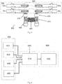
- Figure 9 illustrates an apparatus 900 according to an embodiment of the invention.
- the apparatus 900 is arranged to determine a time-dependent profile of the electromagnetic properties of a metal target 950.
- the apparatus 900 may be utilised to determine or to monitor the evolution of the electromagnetic properties of the metal target 950 as it cools following a hot production process, such as hot rolling.
- the apparatus 900 includes a plurality of electromagnetic sensors 911, 912, 913...91n.
- Each electromagnetic sensor 911, 912, 913...91n may be as described previously with reference to Figure 4 or 5 .
- each electromagnetic sensor 911, 912, 913...91n may not comprise a calibration unit 450, 550. That is, some embodiments of the invention include electromagnetic sensors which do not comprise a calibration unit or circuit, although it will be realised that embodiments may be envisaged which do.
- the system 900 further comprises a plurality of control units 921, 922, 923, 92n, each associated with a respective electromagnetic sensor 911, 912, 913...91n for determining a phase response of the respective electromagnetic sensor 913...91n to the metal target.
- the control units may be individually formed i.e. separately arranged to each provide an output to a monitoring system, or may be arranged as shown in Figure 9 where each control unit is a component part of a control system 920. When combinedly formed, as shown in Figure 9 , it may be possible to reduce an overall number of components via re-use of some sub-systems.
- the control units 921, 922, 923, 92n may be as shown in and described with reference to Figure 6 .
- each control units 921, 922, 923, 92n may not comprise an output for controlling a calibration unit 450, 550.
- Each control unit 921, 922, 923, 92n may comprise one or more excitation signal outputs and one or more detector signal inputs for determining the phase response of the electromagnetic sensor when proximal to the metal target.
- Each control unit 921, 922, 923, 92n is arranged to determine a change in structure of the metal target utilising the respective electromagnetic sensor 911, 912, 913...91n.
- the electromagnetic sensors 911, 912, 913...91n may be arranged proximal to a path of the metal target through one or more cooling zones, as explained above.
- the cooling zones may include means for controllably cooling the metal target.
- the means for controllably cooling the metal target may include one or more means for applying a fluid to the metal target, such as air or other gasses or liquids, such as water or oil.
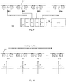
- a rolling direction shown in Figure 10
- the excitation signal may include a plurality of frequency components, as indicated in Figure 10 , although the presence of these multi-frequency components and the number thereof is not limiting.
- the first control unit 921 is arranged to determine a phase response of the electromagnetic sensor at each frequency of the excitation signal. Similarly, as the metal target progresses past each of the second, third and fourth electromagnetic sensors 912, 913, 914, the respective control unit is arranged to determine the sensor response at each frequency of excitation signal and the associated phase response, as shown in Figure 10 .
- the control system 920 may therefore determine the structural development of the metal target in real time. Based on the determined developmental rate, the control system 920 may be arranged to output a signal 930 indicative of the structural development to a processor controller 940 arranged to control the metal production process.
- the signal may indicate a deviation of the structural development of the metal target from a predetermined structural development rate, such that the process controller 940 may vary one or more parameters of the production process to optimise the structural development of the metal target.
- the process controller may reduce a rate of fluid flow toward the metal target, such as by reducing a water flow rate from outlets 125 described above. In this way, the cooling of the metal target may be slowed to a desired rate. In this way, the resulting qualities of the metal target may be controlled by real time monitoring of the structural changes of the metal target.
- the calibration may be performed in an automatically determined period between metal targets.
- an array of electromagnetic sensors is utilised to determine an evolution of a microstructure of a metal target. By such monitoring, properties of the metal target may be controlled.
- embodiments of the present invention can be realised in the form of hardware, software or a combination of hardware and software. Any such software may be stored in the form of volatile or non-volatile storage such as, for example, a storage device like a ROM, whether erasable or rewritable or not, or in the form of memory such as, for example, RAM, memory chips, device or integrated circuits or on an optically or magnetically readable medium such as, for example, a CD, DVD, magnetic disk or magnetic tape. It will be appreciated that the storage devices and storage media are embodiments of machine-readable storage that are suitable for storing a program or programs that, when executed, implement embodiments of the present invention.
- embodiments provide a program comprising code for implementing a system or method as claimed in any preceding claim and a machine readable storage storing such a program. Still further, embodiments of the present invention may be conveyed electronically via any medium such as a communication signal carried over a wired or wireless connection and embodiments suitably encompass the same.
Landscapes
- Physics & Mathematics (AREA)
- Chemical & Material Sciences (AREA)
- General Physics & Mathematics (AREA)
- Engineering & Computer Science (AREA)
- Condensed Matter Physics & Semiconductors (AREA)
- Health & Medical Sciences (AREA)
- Life Sciences & Earth Sciences (AREA)
- Mechanical Engineering (AREA)
- Crystallography & Structural Chemistry (AREA)
- Pathology (AREA)
- Immunology (AREA)
- Biochemistry (AREA)
- Analytical Chemistry (AREA)
- General Health & Medical Sciences (AREA)
- Metallurgy (AREA)
- Thermal Sciences (AREA)
- Organic Chemistry (AREA)
- Materials Engineering (AREA)
- Electrochemistry (AREA)
- Chemical Kinetics & Catalysis (AREA)
- Electromagnetism (AREA)
- Manufacturing & Machinery (AREA)
- Food Science & Technology (AREA)
- Medicinal Chemistry (AREA)
- Investigating Or Analyzing Materials By The Use Of Magnetic Means (AREA)
- Measuring Magnetic Variables (AREA)
- Monitoring And Testing Of Nuclear Reactors (AREA)
Claims (11)
- System zum Überwachen einer Mikrostruktur eines Metall-Targets, umfassend:eine Vielzahl von elektromagnetischen Sensoren (911, 912, 913, ... 91n) zum Ausgeben eines Magnetfelds, wobei ein Erregersignal, das von jedem der elektromagnetischen Sensoren ausgegeben wird, eine Mehrfrequenzwellenform ist, die ein resultierendes Magnetfeld detektiert und als Reaktion darauf ein Detektionssignal ausgibt;ein Steuersystem (920), umfassend eine Vielzahl von Steuereinheiten (921, 922, 923, ... 92n), die jeweils mit einem jeweiligen elektromagnetischen Sensor (911, 912, 913, ... 91n) verbunden und angeordnet sind, um die Detektionssignale von der Vielzahl von elektromagnetischen Sensoren (911, 912, 913, ... 91n)) zu empfangen, um eine Phasenänderung zwischen dem ausgegebenen Magnetfeld und dem resultierenden Magnetfeld an jeder von einer Vielzahl von Frequenzen zu bestimmen, die die Mehrfrequenzwellenform für jeden der Vielzahl von elektromagnetischen Sensoren (911, 912 ,913 , ... 91n) bilden;dadurch gekennzeichnet, dass das Steuersystem angeordnet ist, um eine Mikrostrukturentwicklungsrate eines Metall-Targets an der Vielzahl von elektromagnetischen Sensoren (911, 912, 913, ... 91n)) basierend auf den Phasenänderungen zu bestimmen und um eine Abweichung der Mikrostrukturentwicklungsrate von einer vorher festgelegten Mikrostrukturentwicklungsrate zu bestimmen.
- System nach Anspruch 1, wobei die Vielzahl von elektromagnetischen Sensoren ((911, 912, 913, ... 91n)) in einer Bewegungsrichtung des Metall-Targets angeordnet sind.
- System nach Anspruch 1 oder 2, wobei das Steuersystem (920) angeordnet ist, um eine Mikrostrukturevolution des Metall-Targets zu bestimmen.
- System nach einem der Ansprüche 1 bis 3, wobei das Steuersystem (920) angeordnet ist, um ein Signal auszugeben, das die Abweichung der Mikrostrukturentwicklungsrate des Metall-Targets anzeigt, das System umfassend einen Prozessor (940) zum Steuern eines Herstellungsprozesses, wobei der Prozessor (940) angeordnet ist, um das Signal zu empfangen, das die Abweichung anzeigt, und um einen oder mehrere Parameter des Herstellungsprozesses als Reaktion darauf zu steuern.
- System nach Anspruch 4, wobei der eine oder die mehreren Parameter Parameter eines Prozesses zum Kühlen des Metall-Targets sind.
- System nach Anspruch 4 oder 5, wobei die Vielzahl von elektromagnetischen Sensoren ((911, 912, 913, ... 91n) in einem Kühlbereich des Herstellungsprozesses voneinander beabstandet sind.
- Verfahren zum Überwachen einer Mikrostruktur eines Metall-Targets, umfassend:Ausgeben eines Magnetfelds, das als Reaktion auf eine Mehrfrequenzwellenform an einer Vielzahl von elektromagnetischen Sensoren (911, 912, 913,... 91n) erzeugt wird;Detektieren eines resultierenden Magnetfelds an der Vielzahl von elektromagnetischen Sensoren (911, 912, 913, ... 91n);Bestimmen einer Phasenreaktion des resultierenden Magnetfelds in Bezug auf das ausgegebene Magnetfeld an jeder von einer Vielzahl von Frequenzen, die die Mehrfrequenzwellenform bilden;
gekennzeichnet durchBestimmen einer Mikrostrukturentwicklungsrate eines Metall-Targets an jedem von der Vielzahl von elektromagnetischen Sensoren (911, 912, 913, ... 91n) basierend auf der Phasenreaktion; undBestimmen einer Abweichung der Mikrostrukturentwicklungsrate von einer vorher festgelegten Mikrostrukturentwicklungsrate. - Verfahren nach Anspruch 7, wobei die Mikrostruktur ferner basierend auf einer Größe des resultierenden Magnetfelds in Bezug auf das ausgegebene Magnetfeld bestimmt wird.
- Verfahren nach einem der Ansprüche 7 oder 8, umfassend ein Bestimmen einer mikrostrukturellen Änderungsrate des Metall-Targets.
- Verfahren nach einem der Ansprüche 7 bis 9, umfassend ein Variieren von einem oder mehreren Parametern eines Herstellungsprozesses als Reaktion auf die bestimmte Mikrostruktur.
- Verfahren nach Anspruch 10, wobei der eine oder die mehreren Parameter Kühlparameter des Metall-Targets umfassen.
Priority Applications (1)
| Application Number | Priority Date | Filing Date | Title |
|---|---|---|---|
| PL17164269T PL3203224T3 (pl) | 2011-04-27 | 2012-04-27 | System i sposób monitorowania mikrostruktury metalowego obiektu |
Applications Claiming Priority (3)
| Application Number | Priority Date | Filing Date | Title |
|---|---|---|---|
| GB1107064.6A GB2481482B (en) | 2011-04-27 | 2011-04-27 | Improvements in sensors |
| PCT/GB2012/050930 WO2012146930A2 (en) | 2011-04-27 | 2012-04-27 | Improvements in sensors |
| EP12775825.8A EP2702402B1 (de) | 2011-04-27 | 2012-04-27 | Elektromagnetsensor und dessen kalibrierung |
Related Parent Applications (1)
| Application Number | Title | Priority Date | Filing Date |
|---|---|---|---|
| EP12775825.8A Division EP2702402B1 (de) | 2011-04-27 | 2012-04-27 | Elektromagnetsensor und dessen kalibrierung |
Publications (2)
| Publication Number | Publication Date |
|---|---|
| EP3203224A1 EP3203224A1 (de) | 2017-08-09 |
| EP3203224B1 true EP3203224B1 (de) | 2019-11-27 |
Family
ID=44168634
Family Applications (2)
| Application Number | Title | Priority Date | Filing Date |
|---|---|---|---|
| EP17164269.7A Active EP3203224B1 (de) | 2011-04-27 | 2012-04-27 | System und verfahren zur überwachung einer mikrostruktur einer metallprobe |
| EP12775825.8A Active EP2702402B1 (de) | 2011-04-27 | 2012-04-27 | Elektromagnetsensor und dessen kalibrierung |
Family Applications After (1)
| Application Number | Title | Priority Date | Filing Date |
|---|---|---|---|
| EP12775825.8A Active EP2702402B1 (de) | 2011-04-27 | 2012-04-27 | Elektromagnetsensor und dessen kalibrierung |
Country Status (13)
| Country | Link |
|---|---|
| US (2) | US9404992B2 (de) |
| EP (2) | EP3203224B1 (de) |
| JP (2) | JP6010606B2 (de) |
| KR (1) | KR101941241B1 (de) |
| CN (2) | CN106772139B (de) |
| BR (1) | BR112013027621B1 (de) |
| CA (2) | CA3069899C (de) |
| DK (2) | DK2702402T3 (de) |
| ES (2) | ES2773519T3 (de) |
| GB (1) | GB2481482B (de) |
| PL (2) | PL2702402T3 (de) |
| RU (2) | RU2712981C2 (de) |
| WO (1) | WO2012146930A2 (de) |
Families Citing this family (58)
| Publication number | Priority date | Publication date | Assignee | Title |
|---|---|---|---|---|
| US9823090B2 (en) | 2014-10-31 | 2017-11-21 | Allegro Microsystems, Llc | Magnetic field sensor for sensing a movement of a target object |
| GB2481482B (en) | 2011-04-27 | 2012-06-20 | Univ Manchester | Improvements in sensors |
| US9817078B2 (en) | 2012-05-10 | 2017-11-14 | Allegro Microsystems Llc | Methods and apparatus for magnetic sensor having integrated coil |
| US9846218B2 (en) * | 2012-12-31 | 2017-12-19 | General Electric Company | Calbration of a sensor assembly for use in medical position/orientation tracking |
| US10145908B2 (en) | 2013-07-19 | 2018-12-04 | Allegro Microsystems, Llc | Method and apparatus for magnetic sensor producing a changing magnetic field |
| US10495699B2 (en) | 2013-07-19 | 2019-12-03 | Allegro Microsystems, Llc | Methods and apparatus for magnetic sensor having an integrated coil or magnet to detect a non-ferromagnetic target |
| US9810519B2 (en) | 2013-07-19 | 2017-11-07 | Allegro Microsystems, Llc | Arrangements for magnetic field sensors that act as tooth detectors |
| AT14087U1 (de) * | 2013-12-02 | 2015-04-15 | Ceratizit Austria Gmbh | Verfahren zur Hartmetallkörper-Charakterisierung |
| JP6548868B2 (ja) * | 2014-03-13 | 2019-07-24 | 株式会社東芝 | 磁気検査装置、および紙葉類処理装置 |
| US10209385B2 (en) | 2014-10-03 | 2019-02-19 | Cable Detection Limited | Buried service detection |
| EP3002614B1 (de) * | 2014-10-03 | 2021-02-24 | Cable Detection Limited | Erdeinbaudetektion |
| US9823092B2 (en) | 2014-10-31 | 2017-11-21 | Allegro Microsystems, Llc | Magnetic field sensor providing a movement detector |
| US10712403B2 (en) | 2014-10-31 | 2020-07-14 | Allegro Microsystems, Llc | Magnetic field sensor and electronic circuit that pass amplifier current through a magnetoresistance element |
| US9720054B2 (en) | 2014-10-31 | 2017-08-01 | Allegro Microsystems, Llc | Magnetic field sensor and electronic circuit that pass amplifier current through a magnetoresistance element |
| US9719806B2 (en) | 2014-10-31 | 2017-08-01 | Allegro Microsystems, Llc | Magnetic field sensor for sensing a movement of a ferromagnetic target object |
| SE538669C2 (en) * | 2014-11-28 | 2016-10-11 | Scania Cv Ab | A method of calibrating an evaluation arrangement by sensing magnetic Barkhausen noise |
| CN105548917B (zh) * | 2015-12-08 | 2018-12-07 | 北方工业大学 | 一种非屏蔽环境下磁传感器阵列的校准方法 |
| JP6283965B2 (ja) | 2016-03-18 | 2018-02-28 | 長野県 | 検査装置、検査方法及び非接触式センサ |
| CN105842635B (zh) * | 2016-03-21 | 2018-10-12 | 北京工业大学 | 基于线性外推的微磁探头励磁反馈控制方法 |
| US10989692B2 (en) | 2016-03-21 | 2021-04-27 | Railpod, Inc. | Combined passive and active method and systems to detect and measure internal flaws within metal rails |
| US10260905B2 (en) | 2016-06-08 | 2019-04-16 | Allegro Microsystems, Llc | Arrangements for magnetic field sensors to cancel offset variations |
| US10012518B2 (en) | 2016-06-08 | 2018-07-03 | Allegro Microsystems, Llc | Magnetic field sensor for sensing a proximity of an object |
| US10041810B2 (en) | 2016-06-08 | 2018-08-07 | Allegro Microsystems, Llc | Arrangements for magnetic field sensors that act as movement detectors |
| JP6734989B2 (ja) * | 2016-07-21 | 2020-08-05 | シーメンス・ヘルスケア・ダイアグノスティックス・インコーポレーテッドSiemens Healthcare Diagnostics Inc. | オートメーショントラックのモニタリング及びメンテナンスに基づいて調節するシステム及び方法 |
| CN106646288B (zh) * | 2017-02-21 | 2019-05-14 | 江汉大学 | 一种电磁感应装置 |
| CN106768282B (zh) * | 2017-03-14 | 2023-06-09 | 匙庆磊 | 一种用于磁电式传感器的现场校准系统 |
| US11428755B2 (en) | 2017-05-26 | 2022-08-30 | Allegro Microsystems, Llc | Coil actuated sensor with sensitivity detection |
| US10996289B2 (en) | 2017-05-26 | 2021-05-04 | Allegro Microsystems, Llc | Coil actuated position sensor with reflected magnetic field |
| US10641842B2 (en) | 2017-05-26 | 2020-05-05 | Allegro Microsystems, Llc | Targets for coil actuated position sensors |
| US10310028B2 (en) | 2017-05-26 | 2019-06-04 | Allegro Microsystems, Llc | Coil actuated pressure sensor |
| US10324141B2 (en) | 2017-05-26 | 2019-06-18 | Allegro Microsystems, Llc | Packages for coil actuated position sensors |
| US10837943B2 (en) | 2017-05-26 | 2020-11-17 | Allegro Microsystems, Llc | Magnetic field sensor with error calculation |
| EP3451244B1 (de) * | 2017-08-30 | 2025-01-01 | Robert Bosch GmbH | Vorrichtung und verfahren zur verwendung in mindestens einer herstellung oder behandlung von metallischen materialien |
| JP6782930B2 (ja) * | 2017-09-27 | 2020-11-11 | 日立造船株式会社 | 渦電流探傷装置 |
| DE102017220134A1 (de) * | 2017-11-13 | 2019-05-16 | Bayerische Motoren Werke Aktiengesellschaft | Vorrichtung zur Detektion einer Deformation eines elektrischen Energiespeichers |
| US10866117B2 (en) | 2018-03-01 | 2020-12-15 | Allegro Microsystems, Llc | Magnetic field influence during rotation movement of magnetic target |
| WO2019196998A1 (en) | 2018-04-09 | 2019-10-17 | Københavns Universitet | An eddy-current detector and a method for calibrating such an eddy-current detector |
| EP3810813A1 (de) * | 2018-06-21 | 2021-04-28 | Primetals Technologies USA LLC | Verfahren und system zur steuerung der mikrostruktur eines stahlbandes in einer thermischen verarbeitungsanlage unter verwendung von elektromagnetischen sensoren |
| US11255700B2 (en) | 2018-08-06 | 2022-02-22 | Allegro Microsystems, Llc | Magnetic field sensor |
| US10823586B2 (en) | 2018-12-26 | 2020-11-03 | Allegro Microsystems, Llc | Magnetic field sensor having unequally spaced magnetic field sensing elements |
| US11061084B2 (en) | 2019-03-07 | 2021-07-13 | Allegro Microsystems, Llc | Coil actuated pressure sensor and deflectable substrate |
| JP6984763B2 (ja) | 2019-04-22 | 2021-12-22 | Jfeスチール株式会社 | 圧延鋼板の金属組織評価装置、圧延鋼板の金属組織評価方法、鋼材の製造設備、鋼材の製造方法、及び鋼材の品質管理方法 |
| US10955306B2 (en) | 2019-04-22 | 2021-03-23 | Allegro Microsystems, Llc | Coil actuated pressure sensor and deformable substrate |
| CN110187000B (zh) * | 2019-05-22 | 2023-06-27 | 桂林理工大学 | 一种电磁无损检测双相钢微观组织的方法 |
| CN110057906B (zh) * | 2019-05-23 | 2024-05-03 | 南京师范大学泰州学院 | 一种金属管道工件裂纹快速检测装置 |
| US11280637B2 (en) | 2019-11-14 | 2022-03-22 | Allegro Microsystems, Llc | High performance magnetic angle sensor |
| US11237020B2 (en) | 2019-11-14 | 2022-02-01 | Allegro Microsystems, Llc | Magnetic field sensor having two rows of magnetic field sensing elements for measuring an angle of rotation of a magnet |
| JP6978637B2 (ja) * | 2019-11-20 | 2021-12-08 | 株式会社エー・アンド・デイ | 金属検出器 |
| CN110940940B (zh) * | 2019-12-31 | 2024-07-02 | 鞍山鑫盛矿山自控设备有限公司 | 一种选矿机用磁场梯度检测传感器 |
| US11262422B2 (en) | 2020-05-08 | 2022-03-01 | Allegro Microsystems, Llc | Stray-field-immune coil-activated position sensor |
| CN112958488B (zh) * | 2021-02-11 | 2022-06-03 | 中北大学 | 一种基于电涡流传感器的有色金属分类装置及方法 |
| US11493361B2 (en) | 2021-02-26 | 2022-11-08 | Allegro Microsystems, Llc | Stray field immune coil-activated sensor |
| EP4109087A1 (de) * | 2021-06-21 | 2022-12-28 | NV Bekaert SA | Vorrichtung zur inline-überwachung von bei raumtemperatur mikrostrukturschwankungen |
| US11578997B1 (en) | 2021-08-24 | 2023-02-14 | Allegro Microsystems, Llc | Angle sensor using eddy currents |
| DE102021125036A1 (de) | 2021-09-28 | 2023-03-30 | Alfred-Wegener-Institut, Helmholtz-Zentrum für Polar- und Meeresforschung, Stiftung des öffentlichen Rechts | Kalibrierverfahren für ein elektromagnetisches Induktionsverfahren, Messanordnung zur Durchführung und Anwendung des Verfahrens |
| CN117571814B (zh) * | 2023-11-30 | 2024-04-02 | 科瑞工业自动化系统(苏州)有限公司 | 一种非接触式金属材质检测方法 |
| US12523717B2 (en) | 2024-02-15 | 2026-01-13 | Allegro Microsystems, Llc | Closed loop magnetic field sensor with current control |
| KR102877000B1 (ko) * | 2025-03-28 | 2025-10-27 | 국방과학연구소 | 로켓 슬레드 속도 계측 시스템에 대한 점검을 수행하는 전자 장치의 동작 방법 및 이를 지원하는 전자 장치 |
Family Cites Families (46)
| Publication number | Priority date | Publication date | Assignee | Title |
|---|---|---|---|---|
| GB1385198A (en) * | 1971-07-16 | 1975-02-26 | British Iron Steel Research | Method and apparatus for testing ferromagnetic material |
| FR2258908B1 (de) * | 1974-01-25 | 1976-11-26 | Siderurgie Fse Inst Rech | |
| FR2353068A1 (fr) * | 1976-05-24 | 1977-12-23 | Intersub Dev Sa | Appareil de reperage d'un objet metallique allonge |
| FR2417102A1 (fr) * | 1978-02-14 | 1979-09-07 | Siderurgie Fse Inst Rech | Procede et dispositif pour determiner l'etat magnetique et les variations d'etat magnetique de produits metalliques |
| JPS5920114B2 (ja) | 1979-05-24 | 1984-05-10 | 株式会社豊田中央研究所 | 透磁率測定装置 |
| SU1029070A1 (ru) * | 1981-08-26 | 1983-07-15 | Институт Прикладной Физики Ан Бсср | Способ калибровки и поверки импульсных устройств дл магнитного контрол |
| DE3275441D1 (en) * | 1982-09-22 | 1987-03-19 | Ibm Deutschland | Device to determine the properties of magnetic particle dispersions |
| FR2547589B1 (fr) | 1983-06-14 | 1986-03-21 | Saint Gobain Vitrage | Procede de fabrication de polyvinylbutyral et produits obtenus |
| JPS6017350A (ja) | 1983-07-08 | 1985-01-29 | Kawasaki Steel Corp | 金属の変態率測定方法 |
| CH664632A5 (de) * | 1984-08-16 | 1988-03-15 | Landis & Gyr Ag | Schaltungsanordnung zur kompensation von schwankungen des uebertragungsfaktors eines magnetfeldsensors. |
| EP0177626A1 (de) * | 1984-10-09 | 1986-04-16 | Kawasaki Steel Corporation | System zum On-Line-Erfassen eines Umwandlungswertes und/oder der Ebenheit von Stahl- oder Magnetmaterial |
| JPS6199632A (ja) * | 1984-10-19 | 1986-05-17 | Kawasaki Steel Corp | 熱延鋼板の冷却制御方法 |
| JPS61175562A (ja) | 1985-01-30 | 1986-08-07 | Sumitomo Metal Ind Ltd | 非破壊検査装置 |
| JPS61175562U (de) * | 1985-04-22 | 1986-11-01 | ||
| JPH0651589B2 (ja) | 1986-07-15 | 1994-07-06 | 三井石油化学工業株式会社 | アクリル系レジンモルタル組成物 |
| JPS63253253A (ja) * | 1987-04-10 | 1988-10-20 | Kawasaki Steel Corp | 熱間圧延鋼板の変態率測定方法 |
| JP2897283B2 (ja) | 1989-10-19 | 1999-05-31 | 日本鋼管株式会社 | 磁気探傷装置の校正方法及び装置 |
| JPH03262957A (ja) * | 1990-03-14 | 1991-11-22 | Kobe Steel Ltd | 鋼材の変態率測定装置 |
| FR2663115B1 (fr) | 1990-06-08 | 1994-04-15 | Framatome | Procede et dispositif de controle de l'epaisseur et de la cohesion de l'interface d'un tube duplex. |
| JPH05149923A (ja) * | 1991-11-29 | 1993-06-15 | Kaisei Enjinia Kk | 周波数位相変化による電磁誘導検査装置及びその検査方法 |
| JP3134555B2 (ja) | 1992-11-17 | 2001-02-13 | カシオ計算機株式会社 | 液晶表示素子 |
| JP3555770B2 (ja) | 1993-05-10 | 2004-08-18 | 富士電機リテイルシステムズ株式会社 | 自動販売機 |
| US5420518A (en) * | 1993-09-23 | 1995-05-30 | Schafer, Jr.; Kenneth L. | Sensor and method for the in situ monitoring and control of microstructure during rapid metal forming processes |
| JPH07270383A (ja) | 1994-03-30 | 1995-10-20 | Mitsubishi Heavy Ind Ltd | 渦流探傷装置 |
| JP3050042B2 (ja) | 1994-06-02 | 2000-06-05 | 日本鋼管株式会社 | 変態率測定装置 |
| IT1290736B1 (it) * | 1997-03-24 | 1998-12-10 | Automation Spa Centro | Procedimento di misura delle variazioni di sezione di una barra laminata e relativo dispositivo |
| JPH11295439A (ja) * | 1998-04-07 | 1999-10-29 | Ishida Co Ltd | 異物検出機および異物検出システム |
| JP4192333B2 (ja) | 1999-04-20 | 2008-12-10 | Jfeスチール株式会社 | 鋼材の変態層厚さ計測方法 |
| ATE364187T1 (de) * | 1999-10-13 | 2007-06-15 | Hilti Ag | Induktiver messkopf für metalldetektoren |
| CA2666251C (en) | 1999-12-17 | 2012-02-21 | Geosensors Inc. | Modular electromagnetic sensing apparatus having improved calibration |
| DE19962184A1 (de) * | 1999-12-22 | 2001-07-19 | Siemens Ag | Verfahren und Vorrichtung zur in situ-Ermittlung des Umwandlungsgrads einer nichtmagnetischen Phase in eine ferromagnetische Phase eines metallischen Werkstücks |
| US6750644B1 (en) | 2000-09-06 | 2004-06-15 | General Electric Company | Magnetic field sensor and method for calibrating the same |
| DE60236875D1 (de) * | 2001-08-27 | 2010-08-12 | Takamisawa Cybernetics | Einrichtung und verfahren zum identifizieren eines metallkörpers |
| EP1308721B1 (de) * | 2001-11-02 | 2006-07-26 | Corus Technology BV | Verfahren und Vorrichtung zur Erfassung magnetischer Eigenschaften metallischer Gegenstände |
| WO2005016566A1 (ja) * | 2003-08-13 | 2005-02-24 | Jfe Steel Corporation | 鋼帯または表面処理鋼帯の製造方法 |
| EP1637898A1 (de) * | 2004-09-16 | 2006-03-22 | Liaisons Electroniques-Mecaniques Lem S.A. | Dauerhaft kalibrierter Magnetfeldsensor |
| FR2876800B1 (fr) | 2004-10-18 | 2007-03-02 | Commissariat Energie Atomique | Procede et dispositif de mesure de champ magnetique a l'aide d'un capteur magnetoresitif |
| JP4809039B2 (ja) * | 2005-11-07 | 2011-11-02 | 偕成エンジニア株式会社 | 電磁誘導型検査装置および電磁誘導型検査方法 |
| WO2007088502A2 (en) | 2006-02-03 | 2007-08-09 | Koninklijke Philips Electronics N.V. | Magnetic sensor device with reference unit |
| US20090072815A1 (en) | 2006-04-26 | 2009-03-19 | Koninklijke Philips Electronics N.V. | Calibration of a magnetic sensor device |
| GB0620307D0 (en) * | 2006-10-16 | 2006-11-22 | Ami Semiconductor Belgium Bvba | Auto-calibration of magnetic sensor |
| JP2008185436A (ja) | 2007-01-30 | 2008-08-14 | Jfe Steel Kk | 金属被検体の電磁気特性測定方法及び電磁気特性測定装置 |
| US20080290866A1 (en) * | 2007-05-23 | 2008-11-27 | Cuffe John M | Method and apparatus for digital measurement of an eddy current signal |
| WO2009151449A1 (en) | 2008-06-11 | 2009-12-17 | Halliburton Energy Services, Inc. | Method and system of determining an electrical property of a formation fluid |
| GB2481482B (en) | 2011-04-27 | 2012-06-20 | Univ Manchester | Improvements in sensors |
| UA65098U (ru) * | 2011-05-06 | 2011-11-25 | Институт Кибернетики Им. В.М.Глушкова Нан Украины | Способ калибровки многоканального сквид-магнитометра |
-
2011
- 2011-04-27 GB GB1107064.6A patent/GB2481482B/en active Active
-
2012
- 2012-04-27 EP EP17164269.7A patent/EP3203224B1/de active Active
- 2012-04-27 CA CA3069899A patent/CA3069899C/en not_active Expired - Fee Related
- 2012-04-27 CA CA2871131A patent/CA2871131C/en not_active Expired - Fee Related
- 2012-04-27 ES ES17164269T patent/ES2773519T3/es active Active
- 2012-04-27 RU RU2016126594A patent/RU2712981C2/ru active
- 2012-04-27 KR KR1020137031396A patent/KR101941241B1/ko not_active Expired - Fee Related
- 2012-04-27 CN CN201710055553.0A patent/CN106772139B/zh active Active
- 2012-04-27 DK DK12775825.8T patent/DK2702402T3/en active
- 2012-04-27 BR BR112013027621-5A patent/BR112013027621B1/pt not_active IP Right Cessation
- 2012-04-27 EP EP12775825.8A patent/EP2702402B1/de active Active
- 2012-04-27 PL PL12775825T patent/PL2702402T3/pl unknown
- 2012-04-27 DK DK17164269.7T patent/DK3203224T3/da active
- 2012-04-27 ES ES12775825.8T patent/ES2629318T3/es active Active
- 2012-04-27 CN CN201280031366.4A patent/CN103635798B/zh active Active
- 2012-04-27 PL PL17164269T patent/PL3203224T3/pl unknown
- 2012-04-27 JP JP2014506933A patent/JP6010606B2/ja active Active
- 2012-04-27 US US14/114,006 patent/US9404992B2/en active Active
- 2012-04-27 WO PCT/GB2012/050930 patent/WO2012146930A2/en not_active Ceased
- 2012-04-27 RU RU2013152616/28A patent/RU2593677C2/ru active
-
2016
- 2016-06-09 US US15/177,953 patent/US10144987B2/en active Active
- 2016-09-14 JP JP2016179316A patent/JP6472778B2/ja active Active
Non-Patent Citations (1)
| Title |
|---|
| None * |
Also Published As
Similar Documents
| Publication | Publication Date | Title |
|---|---|---|
| EP3203224B1 (de) | System und verfahren zur überwachung einer mikrostruktur einer metallprobe | |
| Lu et al. | Conductivity Lift-off Invariance and measurement of permeability for ferrite metallic plates | |
| Dickinson et al. | The development of a multifrequency electromagnetic instrument for monitoring the phase transformation of hot strip steel | |
| Shen et al. | Real-time in-line steel microstructure control through magnetic properties using an EM sensor | |
| Hao et al. | Off-line measurement of decarburization of steels using a multifrequency electromagnetic sensor | |
| GB2490393A (en) | Monitoring microstructure of a metal target | |
| Zhu et al. | Modeling and experimental study of a multi-frequency electromagnetic sensor system for rail decarburisation measurement | |
| JP7343575B2 (ja) | 鋼中のオーステナイトの比率のインライン測定のための装置 | |
| WO2019245603A1 (en) | Method and system for control of steel strip microstructure in thermal processing equipment using electro magnetic sensors | |
| Hao et al. | Modelling the electromagnetic response of two-phase steel microstructures | |
| Zhu et al. | Evaluation of rail decarburisation depth using a H-shaped electromagnetic sensor | |
| Yang et al. | In-line quantitative measurement of transformed phase fraction by EM sensors during controlled cooling on the run-out table of a hot strip mill | |
| Johnstone et al. | Using electromagnetic methods to monitor the transformation of steel samples | |
| Shu et al. | The effect of stress and incentive magnetic field on the average volume of magnetic Barkhausen jump in iron | |
| KR100711471B1 (ko) | 열연강판의 변태량 온라인 측정장치 | |
| Moorthy | Distortion Analysis of Magnetic Excitation–Inherent reflection of properties of ferromagnetic materials | |
| Davis et al. | Impedance spectroscopy for remote analysis of steel microstructures | |
| Dobmann | Process integration--A challenge for eddy current and micro-magnetic NDT | |
| Papaelias et al. | Measurement of the Ferrite-Austenite Phase Balance during Transformation in steel using Electromagnetic Sensors |
Legal Events
| Date | Code | Title | Description |
|---|---|---|---|
| PUAI | Public reference made under article 153(3) epc to a published international application that has entered the european phase |
Free format text: ORIGINAL CODE: 0009012 |
|
| STAA | Information on the status of an ep patent application or granted ep patent |
Free format text: STATUS: THE APPLICATION HAS BEEN PUBLISHED |
|
| AC | Divisional application: reference to earlier application |
Ref document number: 2702402 Country of ref document: EP Kind code of ref document: P |
|
| AK | Designated contracting states |
Kind code of ref document: A1 Designated state(s): AL AT BE BG CH CY CZ DE DK EE ES FI FR GB GR HR HU IE IS IT LI LT LU LV MC MK MT NL NO PL PT RO RS SE SI SK SM TR |
|
| STAA | Information on the status of an ep patent application or granted ep patent |
Free format text: STATUS: REQUEST FOR EXAMINATION WAS MADE |
|
| 17P | Request for examination filed |
Effective date: 20180209 |
|
| RBV | Designated contracting states (corrected) |
Designated state(s): AL AT BE BG CH CY CZ DE DK EE ES FI FR GB GR HR HU IE IS IT LI LT LU LV MC MK MT NL NO PL PT RO RS SE SI SK SM TR |
|
| STAA | Information on the status of an ep patent application or granted ep patent |
Free format text: STATUS: EXAMINATION IS IN PROGRESS |
|
| 17Q | First examination report despatched |
Effective date: 20180813 |
|
| GRAP | Despatch of communication of intention to grant a patent |
Free format text: ORIGINAL CODE: EPIDOSNIGR1 |
|
| STAA | Information on the status of an ep patent application or granted ep patent |
Free format text: STATUS: GRANT OF PATENT IS INTENDED |
|
| INTG | Intention to grant announced |
Effective date: 20190618 |
|
| GRAS | Grant fee paid |
Free format text: ORIGINAL CODE: EPIDOSNIGR3 |
|
| GRAA | (expected) grant |
Free format text: ORIGINAL CODE: 0009210 |
|
| STAA | Information on the status of an ep patent application or granted ep patent |
Free format text: STATUS: THE PATENT HAS BEEN GRANTED |
|
| AC | Divisional application: reference to earlier application |
Ref document number: 2702402 Country of ref document: EP Kind code of ref document: P |
|
| AK | Designated contracting states |
Kind code of ref document: B1 Designated state(s): AL AT BE BG CH CY CZ DE DK EE ES FI FR GB GR HR HU IE IS IT LI LT LU LV MC MK MT NL NO PL PT RO RS SE SI SK SM TR |
|
| REG | Reference to a national code |
Ref country code: GB Ref legal event code: FG4D |
|
| REG | Reference to a national code |
Ref country code: CH Ref legal event code: EP |
|
| REG | Reference to a national code |
Ref country code: AT Ref legal event code: REF Ref document number: 1207274 Country of ref document: AT Kind code of ref document: T Effective date: 20191215 |
|
| REG | Reference to a national code |
Ref country code: DE Ref legal event code: R096 Ref document number: 602012066120 Country of ref document: DE |
|
| REG | Reference to a national code |
Ref country code: IE Ref legal event code: FG4D |
|
| REG | Reference to a national code |
Ref country code: FI Ref legal event code: FGE |
|
| REG | Reference to a national code |
Ref country code: CH Ref legal event code: NV Representative=s name: MICHELI AND CIE SA, CH |
|
| REG | Reference to a national code |
Ref country code: DK Ref legal event code: T3 Effective date: 20200225 |
|
| REG | Reference to a national code |
Ref country code: SE Ref legal event code: TRGR |
|
| REG | Reference to a national code |
Ref country code: NL Ref legal event code: FP |
|
| REG | Reference to a national code |
Ref country code: LT Ref legal event code: MG4D |
|
| PG25 | Lapsed in a contracting state [announced via postgrant information from national office to epo] |
Ref country code: BG Free format text: LAPSE BECAUSE OF FAILURE TO SUBMIT A TRANSLATION OF THE DESCRIPTION OR TO PAY THE FEE WITHIN THE PRESCRIBED TIME-LIMIT Effective date: 20200227 Ref country code: NO Free format text: LAPSE BECAUSE OF FAILURE TO SUBMIT A TRANSLATION OF THE DESCRIPTION OR TO PAY THE FEE WITHIN THE PRESCRIBED TIME-LIMIT Effective date: 20200227 Ref country code: GR Free format text: LAPSE BECAUSE OF FAILURE TO SUBMIT A TRANSLATION OF THE DESCRIPTION OR TO PAY THE FEE WITHIN THE PRESCRIBED TIME-LIMIT Effective date: 20200228 Ref country code: LV Free format text: LAPSE BECAUSE OF FAILURE TO SUBMIT A TRANSLATION OF THE DESCRIPTION OR TO PAY THE FEE WITHIN THE PRESCRIBED TIME-LIMIT Effective date: 20191127 Ref country code: LT Free format text: LAPSE BECAUSE OF FAILURE TO SUBMIT A TRANSLATION OF THE DESCRIPTION OR TO PAY THE FEE WITHIN THE PRESCRIBED TIME-LIMIT Effective date: 20191127 |
|
| PG25 | Lapsed in a contracting state [announced via postgrant information from national office to epo] |
Ref country code: IS Free format text: LAPSE BECAUSE OF FAILURE TO SUBMIT A TRANSLATION OF THE DESCRIPTION OR TO PAY THE FEE WITHIN THE PRESCRIBED TIME-LIMIT Effective date: 20200327 Ref country code: HR Free format text: LAPSE BECAUSE OF FAILURE TO SUBMIT A TRANSLATION OF THE DESCRIPTION OR TO PAY THE FEE WITHIN THE PRESCRIBED TIME-LIMIT Effective date: 20191127 Ref country code: RS Free format text: LAPSE BECAUSE OF FAILURE TO SUBMIT A TRANSLATION OF THE DESCRIPTION OR TO PAY THE FEE WITHIN THE PRESCRIBED TIME-LIMIT Effective date: 20191127 |
|
| PG25 | Lapsed in a contracting state [announced via postgrant information from national office to epo] |
Ref country code: AL Free format text: LAPSE BECAUSE OF FAILURE TO SUBMIT A TRANSLATION OF THE DESCRIPTION OR TO PAY THE FEE WITHIN THE PRESCRIBED TIME-LIMIT Effective date: 20191127 |
|
| REG | Reference to a national code |
Ref country code: ES Ref legal event code: FG2A Ref document number: 2773519 Country of ref document: ES Kind code of ref document: T3 Effective date: 20200713 |
|
| PG25 | Lapsed in a contracting state [announced via postgrant information from national office to epo] |
Ref country code: CZ Free format text: LAPSE BECAUSE OF FAILURE TO SUBMIT A TRANSLATION OF THE DESCRIPTION OR TO PAY THE FEE WITHIN THE PRESCRIBED TIME-LIMIT Effective date: 20191127 Ref country code: RO Free format text: LAPSE BECAUSE OF FAILURE TO SUBMIT A TRANSLATION OF THE DESCRIPTION OR TO PAY THE FEE WITHIN THE PRESCRIBED TIME-LIMIT Effective date: 20191127 Ref country code: PT Free format text: LAPSE BECAUSE OF FAILURE TO SUBMIT A TRANSLATION OF THE DESCRIPTION OR TO PAY THE FEE WITHIN THE PRESCRIBED TIME-LIMIT Effective date: 20200419 Ref country code: EE Free format text: LAPSE BECAUSE OF FAILURE TO SUBMIT A TRANSLATION OF THE DESCRIPTION OR TO PAY THE FEE WITHIN THE PRESCRIBED TIME-LIMIT Effective date: 20191127 |
|
| REG | Reference to a national code |
Ref country code: DE Ref legal event code: R097 Ref document number: 602012066120 Country of ref document: DE |
|
| PG25 | Lapsed in a contracting state [announced via postgrant information from national office to epo] |
Ref country code: SM Free format text: LAPSE BECAUSE OF FAILURE TO SUBMIT A TRANSLATION OF THE DESCRIPTION OR TO PAY THE FEE WITHIN THE PRESCRIBED TIME-LIMIT Effective date: 20191127 Ref country code: SK Free format text: LAPSE BECAUSE OF FAILURE TO SUBMIT A TRANSLATION OF THE DESCRIPTION OR TO PAY THE FEE WITHIN THE PRESCRIBED TIME-LIMIT Effective date: 20191127 |
|
| PLBE | No opposition filed within time limit |
Free format text: ORIGINAL CODE: 0009261 |
|
| STAA | Information on the status of an ep patent application or granted ep patent |
Free format text: STATUS: NO OPPOSITION FILED WITHIN TIME LIMIT |
|
| 26N | No opposition filed |
Effective date: 20200828 |
|
| PG25 | Lapsed in a contracting state [announced via postgrant information from national office to epo] |
Ref country code: SI Free format text: LAPSE BECAUSE OF FAILURE TO SUBMIT A TRANSLATION OF THE DESCRIPTION OR TO PAY THE FEE WITHIN THE PRESCRIBED TIME-LIMIT Effective date: 20191127 Ref country code: MC Free format text: LAPSE BECAUSE OF FAILURE TO SUBMIT A TRANSLATION OF THE DESCRIPTION OR TO PAY THE FEE WITHIN THE PRESCRIBED TIME-LIMIT Effective date: 20191127 |
|
| PG25 | Lapsed in a contracting state [announced via postgrant information from national office to epo] |
Ref country code: IE Free format text: LAPSE BECAUSE OF NON-PAYMENT OF DUE FEES Effective date: 20200427 |
|
| PGFP | Annual fee paid to national office [announced via postgrant information from national office to epo] |
Ref country code: LU Payment date: 20210427 Year of fee payment: 10 |
|
| PGFP | Annual fee paid to national office [announced via postgrant information from national office to epo] |
Ref country code: FR Payment date: 20210429 Year of fee payment: 10 Ref country code: FI Payment date: 20210427 Year of fee payment: 10 |
|
| PGFP | Annual fee paid to national office [announced via postgrant information from national office to epo] |
Ref country code: PL Payment date: 20210427 Year of fee payment: 10 Ref country code: SE Payment date: 20210427 Year of fee payment: 10 Ref country code: TR Payment date: 20210427 Year of fee payment: 10 Ref country code: CH Payment date: 20210519 Year of fee payment: 10 Ref country code: DK Payment date: 20210427 Year of fee payment: 10 Ref country code: BE Payment date: 20210427 Year of fee payment: 10 Ref country code: ES Payment date: 20210526 Year of fee payment: 10 Ref country code: AT Payment date: 20210510 Year of fee payment: 10 |
|
| PGFP | Annual fee paid to national office [announced via postgrant information from national office to epo] |
Ref country code: NL Payment date: 20210427 Year of fee payment: 10 |
|
| PG25 | Lapsed in a contracting state [announced via postgrant information from national office to epo] |
Ref country code: MT Free format text: LAPSE BECAUSE OF FAILURE TO SUBMIT A TRANSLATION OF THE DESCRIPTION OR TO PAY THE FEE WITHIN THE PRESCRIBED TIME-LIMIT Effective date: 20191127 Ref country code: CY Free format text: LAPSE BECAUSE OF FAILURE TO SUBMIT A TRANSLATION OF THE DESCRIPTION OR TO PAY THE FEE WITHIN THE PRESCRIBED TIME-LIMIT Effective date: 20191127 |
|
| PG25 | Lapsed in a contracting state [announced via postgrant information from national office to epo] |
Ref country code: MK Free format text: LAPSE BECAUSE OF FAILURE TO SUBMIT A TRANSLATION OF THE DESCRIPTION OR TO PAY THE FEE WITHIN THE PRESCRIBED TIME-LIMIT Effective date: 20191127 |
|
| REG | Reference to a national code |
Ref country code: DK Ref legal event code: EBP Effective date: 20220430 |
|
| REG | Reference to a national code |
Ref country code: SE Ref legal event code: EUG |
|
| REG | Reference to a national code |
Ref country code: CH Ref legal event code: PL |
|
| REG | Reference to a national code |
Ref country code: NL Ref legal event code: MM Effective date: 20220501 |
|
| REG | Reference to a national code |
Ref country code: AT Ref legal event code: MM01 Ref document number: 1207274 Country of ref document: AT Kind code of ref document: T Effective date: 20220427 |
|
| REG | Reference to a national code |
Ref country code: BE Ref legal event code: MM Effective date: 20220430 |
|
| PG25 | Lapsed in a contracting state [announced via postgrant information from national office to epo] |
Ref country code: SE Free format text: LAPSE BECAUSE OF NON-PAYMENT OF DUE FEES Effective date: 20220428 Ref country code: NL Free format text: LAPSE BECAUSE OF NON-PAYMENT OF DUE FEES Effective date: 20220501 Ref country code: LU Free format text: LAPSE BECAUSE OF NON-PAYMENT OF DUE FEES Effective date: 20220427 Ref country code: LI Free format text: LAPSE BECAUSE OF NON-PAYMENT OF DUE FEES Effective date: 20220430 Ref country code: FR Free format text: LAPSE BECAUSE OF NON-PAYMENT OF DUE FEES Effective date: 20220430 Ref country code: FI Free format text: LAPSE BECAUSE OF NON-PAYMENT OF DUE FEES Effective date: 20220427 Ref country code: CH Free format text: LAPSE BECAUSE OF NON-PAYMENT OF DUE FEES Effective date: 20220430 Ref country code: AT Free format text: LAPSE BECAUSE OF NON-PAYMENT OF DUE FEES Effective date: 20220427 |
|
| PG25 | Lapsed in a contracting state [announced via postgrant information from national office to epo] |
Ref country code: BE Free format text: LAPSE BECAUSE OF NON-PAYMENT OF DUE FEES Effective date: 20220430 |
|
| PG25 | Lapsed in a contracting state [announced via postgrant information from national office to epo] |
Ref country code: DK Free format text: LAPSE BECAUSE OF NON-PAYMENT OF DUE FEES Effective date: 20220430 |
|
| P01 | Opt-out of the competence of the unified patent court (upc) registered |
Effective date: 20230518 |
|
| REG | Reference to a national code |
Ref country code: ES Ref legal event code: FD2A Effective date: 20230703 |
|
| PG25 | Lapsed in a contracting state [announced via postgrant information from national office to epo] |
Ref country code: ES Free format text: LAPSE BECAUSE OF NON-PAYMENT OF DUE FEES Effective date: 20220428 |
|
| PG25 | Lapsed in a contracting state [announced via postgrant information from national office to epo] |
Ref country code: PL Free format text: LAPSE BECAUSE OF NON-PAYMENT OF DUE FEES Effective date: 20220427 |
|
| PGFP | Annual fee paid to national office [announced via postgrant information from national office to epo] |
Ref country code: DE Payment date: 20250417 Year of fee payment: 14 |
|
| PGFP | Annual fee paid to national office [announced via postgrant information from national office to epo] |
Ref country code: GB Payment date: 20250417 Year of fee payment: 14 |
|
| PGFP | Annual fee paid to national office [announced via postgrant information from national office to epo] |
Ref country code: IT Payment date: 20250430 Year of fee payment: 14 |