EP3203005B1 - Rohrförmige antriebseinrichtung - Google Patents
Rohrförmige antriebseinrichtung Download PDFInfo
- Publication number
- EP3203005B1 EP3203005B1 EP17154183.2A EP17154183A EP3203005B1 EP 3203005 B1 EP3203005 B1 EP 3203005B1 EP 17154183 A EP17154183 A EP 17154183A EP 3203005 B1 EP3203005 B1 EP 3203005B1
- Authority
- EP
- European Patent Office
- Prior art keywords
- electric motor
- circuit board
- drive mechanism
- spindle
- electronic circuit
- Prior art date
- Legal status (The legal status is an assumption and is not a legal conclusion. Google has not performed a legal analysis and makes no representation as to the accuracy of the status listed.)
- Active
Links
- 238000004590 computer program Methods 0.000 claims description 2
- 239000000463 material Substances 0.000 claims 1
- 239000007779 soft material Substances 0.000 claims 1
- 230000005540 biological transmission Effects 0.000 description 2
- 230000001276 controlling effect Effects 0.000 description 2
- 230000006835 compression Effects 0.000 description 1
- 238000007906 compression Methods 0.000 description 1
- 238000004146 energy storage Methods 0.000 description 1
- 230000001681 protective effect Effects 0.000 description 1
- 230000001105 regulatory effect Effects 0.000 description 1
Images
Classifications
-
- E—FIXED CONSTRUCTIONS
- E05—LOCKS; KEYS; WINDOW OR DOOR FITTINGS; SAFES
- E05F—DEVICES FOR MOVING WINGS INTO OPEN OR CLOSED POSITION; CHECKS FOR WINGS; WING FITTINGS NOT OTHERWISE PROVIDED FOR, CONCERNED WITH THE FUNCTIONING OF THE WING
- E05F15/00—Power-operated mechanisms for wings
- E05F15/60—Power-operated mechanisms for wings using electrical actuators
- E05F15/603—Power-operated mechanisms for wings using electrical actuators using rotary electromotors
- E05F15/611—Power-operated mechanisms for wings using electrical actuators using rotary electromotors for swinging wings
- E05F15/616—Power-operated mechanisms for wings using electrical actuators using rotary electromotors for swinging wings operated by push-pull mechanisms
- E05F15/622—Power-operated mechanisms for wings using electrical actuators using rotary electromotors for swinging wings operated by push-pull mechanisms using screw-and-nut mechanisms
-
- F—MECHANICAL ENGINEERING; LIGHTING; HEATING; WEAPONS; BLASTING
- F16—ENGINEERING ELEMENTS AND UNITS; GENERAL MEASURES FOR PRODUCING AND MAINTAINING EFFECTIVE FUNCTIONING OF MACHINES OR INSTALLATIONS; THERMAL INSULATION IN GENERAL
- F16H—GEARING
- F16H25/00—Gearings comprising primarily only cams, cam-followers and screw-and-nut mechanisms
- F16H25/18—Gearings comprising primarily only cams, cam-followers and screw-and-nut mechanisms for conveying or interconverting oscillating or reciprocating motions
- F16H25/20—Screw mechanisms
-
- E—FIXED CONSTRUCTIONS
- E05—LOCKS; KEYS; WINDOW OR DOOR FITTINGS; SAFES
- E05Y—INDEXING SCHEME ASSOCIATED WITH SUBCLASSES E05D AND E05F, RELATING TO CONSTRUCTION ELEMENTS, ELECTRIC CONTROL, POWER SUPPLY, POWER SIGNAL OR TRANSMISSION, USER INTERFACES, MOUNTING OR COUPLING, DETAILS, ACCESSORIES, AUXILIARY OPERATIONS NOT OTHERWISE PROVIDED FOR, APPLICATION THEREOF
- E05Y2201/00—Constructional elements; Accessories therefor
- E05Y2201/40—Motors; Magnets; Springs; Weights; Accessories therefor
- E05Y2201/43—Motors
- E05Y2201/434—Electromotors; Details thereof
-
- E—FIXED CONSTRUCTIONS
- E05—LOCKS; KEYS; WINDOW OR DOOR FITTINGS; SAFES
- E05Y—INDEXING SCHEME ASSOCIATED WITH SUBCLASSES E05D AND E05F, RELATING TO CONSTRUCTION ELEMENTS, ELECTRIC CONTROL, POWER SUPPLY, POWER SIGNAL OR TRANSMISSION, USER INTERFACES, MOUNTING OR COUPLING, DETAILS, ACCESSORIES, AUXILIARY OPERATIONS NOT OTHERWISE PROVIDED FOR, APPLICATION THEREOF
- E05Y2201/00—Constructional elements; Accessories therefor
- E05Y2201/60—Suspension or transmission members; Accessories therefor
- E05Y2201/622—Suspension or transmission members elements
- E05Y2201/696—Screw mechanisms
- E05Y2201/70—Nuts
-
- E—FIXED CONSTRUCTIONS
- E05—LOCKS; KEYS; WINDOW OR DOOR FITTINGS; SAFES
- E05Y—INDEXING SCHEME ASSOCIATED WITH SUBCLASSES E05D AND E05F, RELATING TO CONSTRUCTION ELEMENTS, ELECTRIC CONTROL, POWER SUPPLY, POWER SIGNAL OR TRANSMISSION, USER INTERFACES, MOUNTING OR COUPLING, DETAILS, ACCESSORIES, AUXILIARY OPERATIONS NOT OTHERWISE PROVIDED FOR, APPLICATION THEREOF
- E05Y2201/00—Constructional elements; Accessories therefor
- E05Y2201/60—Suspension or transmission members; Accessories therefor
- E05Y2201/622—Suspension or transmission members elements
- E05Y2201/696—Screw mechanisms
- E05Y2201/702—Spindles; Worms
-
- E—FIXED CONSTRUCTIONS
- E05—LOCKS; KEYS; WINDOW OR DOOR FITTINGS; SAFES
- E05Y—INDEXING SCHEME ASSOCIATED WITH SUBCLASSES E05D AND E05F, RELATING TO CONSTRUCTION ELEMENTS, ELECTRIC CONTROL, POWER SUPPLY, POWER SIGNAL OR TRANSMISSION, USER INTERFACES, MOUNTING OR COUPLING, DETAILS, ACCESSORIES, AUXILIARY OPERATIONS NOT OTHERWISE PROVIDED FOR, APPLICATION THEREOF
- E05Y2400/00—Electronic control; Electrical power; Power supply; Power or signal transmission; User interfaces
- E05Y2400/10—Electronic control
- E05Y2400/44—Sensors not directly associated with the wing movement
-
- E—FIXED CONSTRUCTIONS
- E05—LOCKS; KEYS; WINDOW OR DOOR FITTINGS; SAFES
- E05Y—INDEXING SCHEME ASSOCIATED WITH SUBCLASSES E05D AND E05F, RELATING TO CONSTRUCTION ELEMENTS, ELECTRIC CONTROL, POWER SUPPLY, POWER SIGNAL OR TRANSMISSION, USER INTERFACES, MOUNTING OR COUPLING, DETAILS, ACCESSORIES, AUXILIARY OPERATIONS NOT OTHERWISE PROVIDED FOR, APPLICATION THEREOF
- E05Y2400/00—Electronic control; Electrical power; Power supply; Power or signal transmission; User interfaces
- E05Y2400/65—Power or signal transmission
-
- E—FIXED CONSTRUCTIONS
- E05—LOCKS; KEYS; WINDOW OR DOOR FITTINGS; SAFES
- E05Y—INDEXING SCHEME ASSOCIATED WITH SUBCLASSES E05D AND E05F, RELATING TO CONSTRUCTION ELEMENTS, ELECTRIC CONTROL, POWER SUPPLY, POWER SIGNAL OR TRANSMISSION, USER INTERFACES, MOUNTING OR COUPLING, DETAILS, ACCESSORIES, AUXILIARY OPERATIONS NOT OTHERWISE PROVIDED FOR, APPLICATION THEREOF
- E05Y2900/00—Application of doors, windows, wings or fittings thereof
- E05Y2900/50—Application of doors, windows, wings or fittings thereof for vehicles
- E05Y2900/53—Type of wing
- E05Y2900/531—Doors
- E05Y2900/532—Back doors or end doors
-
- E—FIXED CONSTRUCTIONS
- E05—LOCKS; KEYS; WINDOW OR DOOR FITTINGS; SAFES
- E05Y—INDEXING SCHEME ASSOCIATED WITH SUBCLASSES E05D AND E05F, RELATING TO CONSTRUCTION ELEMENTS, ELECTRIC CONTROL, POWER SUPPLY, POWER SIGNAL OR TRANSMISSION, USER INTERFACES, MOUNTING OR COUPLING, DETAILS, ACCESSORIES, AUXILIARY OPERATIONS NOT OTHERWISE PROVIDED FOR, APPLICATION THEREOF
- E05Y2900/00—Application of doors, windows, wings or fittings thereof
- E05Y2900/50—Application of doors, windows, wings or fittings thereof for vehicles
- E05Y2900/53—Type of wing
- E05Y2900/546—Tailboards, tailgates or sideboards opening upwards
-
- F—MECHANICAL ENGINEERING; LIGHTING; HEATING; WEAPONS; BLASTING
- F16—ENGINEERING ELEMENTS AND UNITS; GENERAL MEASURES FOR PRODUCING AND MAINTAINING EFFECTIVE FUNCTIONING OF MACHINES OR INSTALLATIONS; THERMAL INSULATION IN GENERAL
- F16H—GEARING
- F16H25/00—Gearings comprising primarily only cams, cam-followers and screw-and-nut mechanisms
- F16H25/18—Gearings comprising primarily only cams, cam-followers and screw-and-nut mechanisms for conveying or interconverting oscillating or reciprocating motions
- F16H25/20—Screw mechanisms
- F16H2025/2031—Actuator casings
-
- F—MECHANICAL ENGINEERING; LIGHTING; HEATING; WEAPONS; BLASTING
- F16—ENGINEERING ELEMENTS AND UNITS; GENERAL MEASURES FOR PRODUCING AND MAINTAINING EFFECTIVE FUNCTIONING OF MACHINES OR INSTALLATIONS; THERMAL INSULATION IN GENERAL
- F16H—GEARING
- F16H25/00—Gearings comprising primarily only cams, cam-followers and screw-and-nut mechanisms
- F16H25/18—Gearings comprising primarily only cams, cam-followers and screw-and-nut mechanisms for conveying or interconverting oscillating or reciprocating motions
- F16H25/20—Screw mechanisms
- F16H2025/2062—Arrangements for driving the actuator
- F16H2025/2075—Coaxial drive motors
Definitions
- the present invention relates to a tubular drive device for a flap of a vehicle, preferably a tailgate or door, with two telescopically nested tubes whose free ends are hinged respectively to the flap of the vehicle and to the vehicle itself, wherein the tubes by means of one of a Electric motor driven spindle can be moved apart and together with a spindle nut arranged thereon, so as to open the flap and close.
- the electric motor, spindle and spindle nut and an electronic board with sensor elements are arranged within the tubular drive device.
- Such tubular drive devices are mounted instead of the usual gas springs, for example, on a tailgate of a motor vehicle to open the tailgate automatically or by remote control and close.
- the size of these drive devices may not be much larger than the size of the gas springs commonly used. Nevertheless, the drive device must cover a relatively long work area, without even be longer than the usual gas springs.
- the electronic circuit board between the electric motor and the free end of the electric motor-carrying tube directly to the electric motor.
- the PWM frequency acted lines are particularly short, as well as the voltage drop between the electronics and the motor is minimized.
- the electronic board in the form of a disc and is arranged perpendicular to the axis of symmetry of the tubes. In this way, the entire electronics requires only the smallest possible space.
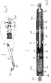
- FIG. 1 shows a three-dimensional representation of an embodiment of the drive device 1 according to the invention, which has the dimensions and substantially the appearance of a classic gas spring for supporting a tailgate.
- the illustrated drive device 1 has a housing tube 10, on which an overtube 20 is guided telescopically displaceable.
- At the two free ends of the nested tubes 10 and 20 are each ball cups 30, 40 are arranged by means of which the drive means, for example, with the tailgate and the body of a motor vehicle in the same manner is connected, as previously done with gas springs.
- the spindle nut 70 is connected to one end of a threaded spindle 60 coaxially enclosing the spindle tube 80, at the other end a ball socket 30 is fixedly arranged.
- the spindle nut 70 is axially displaceably guided in a guide tube 90 surrounding the spindle tube 80, which is fixedly connected to the housing tube 10.
- a helical compression spring 10 is arranged, which is axially supported at one end to the overtube 2 in the region of a ball socket 30 and with its other end to the housing tube 10 ,
- the threaded spindle 60 carries at its end facing a ball socket 30 a guide sleeve 110, with its cylindrical surface, the threaded spindle 60 is guided axially displaceably in the spindle tube 80.
- the guide tube 90 has axial slots which extend substantially over its length.
- radially projecting support pins are arranged on the spindle nut, which protrude radially into the axial slots and ensure an anti-rotation of the spindle nut 70 relative to the guide tube 90,
- the threaded spindle 60 is axially supported via the bearing 50.
- An output shaft 14 of a transmission 15 is connected coaxially rotatably with the threaded spindle 60, wherein the transmission 15 via a further output shaft 17 of an electric motor 16 is rotatably driven.
- the further output shaft 17 also protrudes on the side facing away from the gear 15 from the electric motor 16 and carries on its free end a permanent magnet 18 which axially opposite a hall elements 19, arranged stationary electronics board 200 opposite.
- the second ball socket 40 is connected to the housing tube 10 by means of a closure lid 24.
- carries the substantially disc-shaped electronic board 200 as shown in FIG. 2 shown in the drive device 1 is arranged in a vertical position to the axis of rotation of the tubes 10 and 20, not only the Hall elements 19, but also the power switch 210 and the control of these power switch 210 required electronic circuits 220, in which the computer programs for controlling the Circuit breaker are stored.
- the present invention achieves the same length as the original drive means optimal shielding against the interference frequencies of the pulse width modulation and a minimum voltage drop between the power electronics and the electric motor.
- the electronic board 200 also has a Temperature sensor 230 include, which is optimally arranged by the inventive arrangement of the electronic board to monitor the operating temperature of the electric motor 16.
Landscapes
- Engineering & Computer Science (AREA)
- General Engineering & Computer Science (AREA)
- Mechanical Engineering (AREA)
- Power-Operated Mechanisms For Wings (AREA)
- Measuring Temperature Or Quantity Of Heat (AREA)
- Connection Of Motors, Electrical Generators, Mechanical Devices, And The Like (AREA)
Description
- Die vorliegende Erfindung betrifft eine rohrförmige Antriebseinrichtung für eine Klappe eines Fahrzeugs, vorzugsweise eine Heckklappe oder Tür, mit zwei teleskopisch ineinander gesteckten Rohren, deren freie Enden jeweils an der Klappe des Fahrzeugs und an dem Fahrzeug selbst angelenkt sind, wobei die Rohre mittels einer von einem Elektromotor angetriebenen Spindel mit einer darauf angeordneten Spindelmutter auseinander- und zusammengefahren werden können, um so die Klappe zu öffnen und zu schließen. Dabei sind Elektromotor, Spindel und Spindelmutter sowie eine Elektronikplatine mit Sensor-elementen innerhalb der rohrförmigen Antriebseinrichtung angeordnet.
- Solche rohrförmigen Antriebseinrichtungen werden an Stelle der üblichen Gasfedern beispielsweise an einer Heckklappe eines Kraftfahrzeugs angebracht, um die Heckklappe automatisch bzw. per Fernbedienung öffnen und schließen zu können. Von entscheidender Bedeutung ist es dabei, dass die Baugröße dieser Antriebseinrichtungen nicht wesentlich größer werden darf, als die Baugröße der üblicherweise verwendeten Gasfedern. Trotzdem muss die Antriebseinrichtung einen relativ langen Arbeitsbereich überdecken, ohne selbst länger als die üblichen Gasfedern zu werden.
- Bisher erfolgte die Ansteuerung solcher Antriebseinrichtungen üblicherweise durch eine separate Leistungselektronik in einem eigenen Gehäuse, die die Fahrgeschwindigkeit des Elektromotors der Antriebseinrichtung über Pulsweitenmodulation geregelt hat. In der Antriebseinrichtung selbst befand sich nur eine kleine Sensorplatine, die, meist mittels Hallsensoren, Bewegungsrichtung und Bewegungsgeschwindigkeit der Klappe erfasst hat. Die Leistungselektronik zur Steuerung des Antriebsmotors musste irgendwo im Fahrzeug untergebracht werden. Dies führte dazu, dass noch an anderer Stelle im Fahrzeug Platz verbraucht wurde, ein zusätzliches Bauteil verbaut werden musste, und der PWM-gepulste Betriebsstrom über längere Leitungen übertragen werden musste. Insbesondere Letzteres führte regelmäßig zu erheblichen Problemen mit der elektro-magnetischen Verträglichkeit. Die Verbindungsleitungen zwischen der Leistungselektronik und der Antriebseinrichtung führten durch die 20 kHz-Pulsweitenmodulationsfrequenz zu erheblichen Störabstrahlungen. Des weiteren führten die nicht unerheblichen Leitungs-längen und die zusätzlich erforderlichen Steckverbinder darüber hinaus zu einem erheblichen Spannungsabfall über den Gesamtwiderstand der Leitung und der diversen nach dem Stand der Technik erforderlichen Steckverbinder. Heute beträgt der Gesamtwiderstand bei den Antriebseinrichtungen gemäß dem Stand der Technik etwa 250 mΩ. Dies bedeutet bei einem Motorstrom von 10 A 2,5 V Spannungsverlust, was bei einem 12 V-Netz bereits zu erheblichen Problemen führen kann.
- Diese Problematik wurde bereits bei dem nächstgelegenen Stand der Technik, der
DE 10 2008 030 247 A1 des gleichen Anmelders erkannt. Hier hat man dann versucht, die sonst in einem separaten Gehäuse als eigenes Gerät vorgesehene Leistungselektronik sowie einen elektrischen Energiespeicher direkt in die Antriebseinrichtung einzubauen. Dadurch hat sich dann aber die Baulänge der Antriebseinrichtung in unzulässiger Weise vergrößert, so dass diese Lösung nicht umsetzbar war, da die Antriebsvorrichtung gemäß diesem Stand der Technik nicht mehr in den ursprünglich für die Gasfeder vorgesehen Bauraum passte. - Ferner sei an dieser Stelle auf die Dokumente
EP 0 854 262 A2 , die die Merkmale des Oberbegriffs des Anspruchs 1 offenbart,DE 20 2011 109760 U1 undDE 10 2006 030986 A1 hingewiesen. - Ausgehend von diesem Stand der Technik ist es daher Aufgabe der vorliegenden Erfindung, eine rohrförmige Antriebseinrichtung zu schaffen, die problemlos anstelle der Gasfedern beispielsweise in der Heckklappe eines Kraftfahrzeugs verbaut werden kann, und die trotzdem keine Störabstrahlungen (EMV) verursacht und auch den Spannungsabfall über die Anschlussleitungen, insbesondere beim Beginn des Öffnens der Klappe gering hält.
- Erfindungsgemäß ist es erstmals gelungen, die Leistungselektronik für die Ansteuerung des Elektromotors so weit zu miniaturisieren, dass diese auf der auch bei den Antriebseinrichtungen des Standes der Technik vorhandenen Sensorplatine zusätzlich Platz findet, so dass kein weiterer Bauraum für die Leistungselektronik vorgesehen werden muss, wodurch die Baugröße der Antriebseinrichtung unzulässig wachsen würde.
- Es ist dabei besonders bevorzugt, die Elektronikplatine zwischen dem Elektromotor und dem freien Ende des den Elektromotor tragenden Rohres direkt am Elektromotor anzuordnen. Auf diese Weise werden die PWM-Frequenz beaufschlagten Leitungswege besonders kurz, ebenso wird der Spannungsabfall zwischen der Elektronik und dem Motor minimiert.
- Erfindungsgemäß weist die Elektronikplatine die Form einer Scheibe auf und ist senkrecht zur Symmetrieachse der Rohre angeordnet. Auf diese Weise benötigt die gesamte Elektronik nur den geringstmöglichen Bauraum.
- Weiter ist es besonders bevorzugt, wenn die Elektronikplatine dann einen Temperatursensor umfasst. Da die Platine so nahe an dem Motor angeordnet werden kann, kann durch einfache Temperaturmessung auf der Platine erkannt werden, wenn der Motor sich überhitzen sollte. Es können dann entsprechende Schutzmaßnahmen über die Steuer-software der Leistungselektronik getroffen werden, beispielsweise Verringerung des Ansteuerungsstromes oder Abschaltung des Motors. Im Folgenden wird die vorliegende Erfindung anhand des in den Zeichnungen dargestellten Ausführungsbeispiels näher erläutert. Es zeigt:
-
Figur 1 eine dreidimensionale Darstellung einer Ausführungsform einer erfindungsgemäßen Antriebsvorrichtung mit als Detail herausvergrößerter Elektronikplatine; und -
Figur 2 eine Schnittdarstellung durch die Antriebsvorrichtung derFigur 1 . -
Figur 1 zeigt eine dreidimensionale Darstellung einer Ausführungsform der erfindungsgemäßen Antriebsvorrichtung 1, die die Abmaße und im wesentlichen auch das Aussehen einer klassischen Gasfeder zum Abstützen einer Heckklappe aufweist. Die dargestellte Antriebseinrichtung 1 besitzt ein Gehäuserohr 10, an dem ein Überrohr 20 teleskopisch verschiebbar geführt ist.
An den beiden freien Enden der ineinandergesteckten Rohre 10 und 20 sind jeweils Kugelpfannen 30, 40 angeordnet, mittels derer die Antriebseinrichtung beispielsweise mit der Heckklappe und der Karosserie eines Kraftfahrzeuges in gleicher Weise verbindbar ist, wie dies bisher mit Gasfedern geschieht. - Der detailliertere Aufbau der Antriebseinrichtung ergibt sich aus der
Figur 2 . In einem dem Überrohr 20 zugewandten Endbereich des Gehäuserohres 10 ist ein Lager 50 fest eingebaut, an dem ein Ende einer koaxial in das Überrohr 20 ragenden Gewindespindel 60 drehbar gelagert ist. Auf der Gewindespindel 60 ist eine Spindelmutter 70 gegenüber dem Gehäuserohr 10 drehfest angeordnet. - Die Spindelmutter 70 ist mit einem Ende eines die Gewindespindel 60 koaxial umschließenden Spindelrohrs 80 verbunden, an dessen anderem Ende die eine Kugelpfanne 30 fest angeordnet ist.
Die Spindelmutter 70 ist in einem das Spindelrohr 80 umschließenden Führungsrohr 90 axial verschiebbar geführt, das mit dem Gehäuserohr 10 fest verbunden ist. In dem Ringspalt zwischen dem Führungsrohr 90 und dem dieses mit radialem Abstand koaxial umschließenden Überrohr 20 ist eine Schraubendruckfeder 10 angeordnet, die mit ihrem einen Ende an dem Überrohr 2 im Bereich der einen Kugelpfanne 30 und mit ihrem anderen Ende an dem Gehäuserohr 10 axial abgestützt ist. Die Gewindespindel 60 trägt an ihrem der einen Kugelpfanne 30 zugewandten Ende eine Führungshülse 110, mit deren zylindrischer Mantelfläche die Gewindespindel 60 in dem Spindelrohr 80 axial verschiebbar geführt ist. Das Führungsrohr 90 besitzt axiale Schlitze, die sich weitgehend über dessen Länge erstrecken. Entsprechend der axialen Schlitze sind an der Spindelmutter 70 radial hervor-stehende Abstützzapfen angeordnet, die in die axialen Schlitze radial hineinragen und für eine Verdrehsicherung der Spindelmutter 70 gegenüber dem Führungsrohr 90 sorgen, - Die Gewindespindel 60 ist über das Lager 50 axial abgestützt.
- Eine Abtriebswelle 14 eines Getriebes 15 ist koaxial drehfest mit der Gewindespindel 60 verbunden, wobei das Getriebe 15 über eine weitere Abtriebswelle 17 eines Elektromotors 16 drehbar antreibbar ist.
- Die weitere Abtriebswelle 17 ragt auch auf der dem Getriebe 15 abgewandten Seite aus dem Elektromotor 16 heraus und trägt auf ihrem freien Ende einen Dauermagnet 18, der axial einer Hallelemente 19 aufweisenden, feststehend angeordneten Elektronikplatine 200 gegenüberliegt. Die zweite Kugelpfanne 40 ist mittels eines Verschlussdeckels 24 mit dem Gehäuserohr 10 verbunden.
Wie in der Detaildarstellung vonFigur 1 gezeigt, trägt die im wesentlichen scheibenförmige Elektronikplatine 200, die wie inFigur 2 dargestellt in der Antriebseinrichtung 1 in senkrechter Lage zu der Rotationsachse der Rohre 10 und 20 angeordnet ist, nicht nur die Hallelemente 19, sondern auch die Leistungsschalter 210 sowie die zur Ansteuerung dieser Leistungsschalter 210 erforderlichen elektronischen Schaltkreise 220, in denen auch die Computerprogramme zur Steuerung der Leistungsschalter gespeichert sind. - Auf diese Weise erreicht die vorliegende Erfindung bei gleicher Baulänge wie die ursprünglichen Antriebseinrichtungen eine optimale Abschirmung gegen die Störfrequenzen der Pulsweitenmodulation und einen minimalen Spannungsabfall zwischen der Leistungselektronik und dem Elektromotor.
- Vorzugsweise kann die Elektronikplatine 200 auch noch einen Temperatursensor 230 umfassen, der durch die erfindungsgemäße Anordnung der Elektronikplatine optimal angeordnet ist, um die Betriebstemperatur des Elektromotors 16 zu überwachen.
Claims (5)
- Rohrförmige Antriebseinrichtung (1) für eine Klappe eines Fahrzeugs, vorzugsweise einen Heckdeckel, eine Heckklappe oder Tür,
mit zwei teleskopisch ineinander gesteckten Rohren (10, 20), deren freie Enden (30, 40) jeweils an der Klappe des Fahrzeugs und an dem Fahrzeug selbst anlenkbar sind,
wobei die Rohre (10, 20) mittels einer von einem Elektromotor (16) angetriebenen Spindel (60) mit einer darauf angeordneten Spindelmutter (70) auseinander- und zusammengefahren werden können, um so die Klappe zu öffnen und zu schließen,
wobei Elektromotor (16), Spindel (60) und Spindelmutter (70) sowie eine Elektronikplatine (200) mit Sensorelementen (19, 230) innerhalb der rohrförmigen Antriebseinrichtung (1) angeordnet sind,
wobei die Elektronikplatine (200) die Form einer Scheibe aufweist und senkrecht zur Symmetrieachse der Rohre (10, 20) angeordnet ist, und
wobei auf derselben Elektronikplatine (200) zusätzlich auch eine Leistungselektronik (210) für die Ansteuerung des Elektromotors (16) angeordnet ist,
dadurch gekennzeichnet, dass die Elektronikplatine (200) Hallelemente, Leistungsschalter und zur Ansteuerung dieser Leistungsschalter erforderliche elektronische Schaltkreise, in welchen Computerprogramme zur Steuerung der Leistungsschalter gespeichert sind, umfasst. - Antriebseinrichtung nach Anspruch 1, dadurch gekennzeichnet, dass die Elektronikplatine (200) zwischen dem Elektromotor (16) und dem freien Ende (40) des den Elektromotor (16) tragenden Rohres (10) am Elektromotor (16) angeordnet ist.
- Antriebseinrichtung nach Anspruch 2, dadurch gekennzeichnet, dass die Elektronikplatine (200) auch einen Temperatursensor (230) umfasst.
- Antriebseinrichtung nach einem der vorhergehenden Ansprüche, dadurch gekennzeichnet, dass das Gehäuserohr (10) aus einem Werkstoff hoher elektrischer Leitfähigkeit ausgebildet ist.
- Antriebseinrichtung nach Anspruch 4, dadurch gekennzeichnet, dass das Gehäuserohr (10) aus einem weichmagnetischen Werkstoff besteht.
Applications Claiming Priority (1)
| Application Number | Priority Date | Filing Date | Title |
|---|---|---|---|
| DE102016201772.1A DE102016201772A1 (de) | 2016-02-05 | 2016-02-05 | Rohrförmige Antriebseinrichtung |
Publications (2)
| Publication Number | Publication Date |
|---|---|
| EP3203005A1 EP3203005A1 (de) | 2017-08-09 |
| EP3203005B1 true EP3203005B1 (de) | 2019-08-07 |
Family
ID=58094140
Family Applications (1)
| Application Number | Title | Priority Date | Filing Date |
|---|---|---|---|
| EP17154183.2A Active EP3203005B1 (de) | 2016-02-05 | 2017-02-01 | Rohrförmige antriebseinrichtung |
Country Status (5)
| Country | Link |
|---|---|
| US (1) | US10214952B2 (de) |
| EP (1) | EP3203005B1 (de) |
| JP (1) | JP7085797B2 (de) |
| CN (1) | CN107044240B (de) |
| DE (1) | DE102016201772A1 (de) |
Cited By (2)
| Publication number | Priority date | Publication date | Assignee | Title |
|---|---|---|---|---|
| US11837926B2 (en) | 2020-12-23 | 2023-12-05 | Black & Decker, Inc. | Brushless DC motor with stator teeth having multiple parallel sets of windings |
| US11984771B2 (en) | 2018-03-02 | 2024-05-14 | Black & Decker Inc. | Circuit board for connecting motor windings |
Families Citing this family (7)
| Publication number | Priority date | Publication date | Assignee | Title |
|---|---|---|---|---|
| JPWO2016010145A1 (ja) * | 2014-07-17 | 2017-04-27 | 株式会社ExH | 電力供給システム |
| US20200300325A1 (en) * | 2014-09-19 | 2020-09-24 | Barnes Group Inc. | Electromechanical Spring System |
| DE102017115183A1 (de) * | 2017-07-06 | 2019-01-10 | Edscha Engineering Gmbh | Antriebsvorrichtung für eine Fahrzeugklappe |
| US10916396B2 (en) | 2017-08-24 | 2021-02-09 | Yazaki Corporation | Load controller and load control method |
| CN107780752A (zh) * | 2017-11-30 | 2018-03-09 | 无锡典聚科技有限公司 | 一种电动尾门撑杆导向管止转结构 |
| DE102020132084A1 (de) | 2020-12-03 | 2022-06-09 | Schaeffler Technologies AG & Co. KG | Spindeltrieb |
| CN112815060A (zh) * | 2021-01-27 | 2021-05-18 | 麦格纳汽车系统(苏州)有限公司 | 一种分体式丝杠套管 |
Citations (2)
| Publication number | Priority date | Publication date | Assignee | Title |
|---|---|---|---|---|
| DE102005059051A1 (de) | 2005-12-08 | 2007-06-14 | Kiekert Ag | Kompakter Schwenkantrieb für Fahrzeugklappen |
| DE102008030247A1 (de) | 2008-06-25 | 2010-01-07 | Stabilus Gmbh | Antriebseinrichtung |
Family Cites Families (27)
| Publication number | Priority date | Publication date | Assignee | Title |
|---|---|---|---|---|
| US4177499A (en) * | 1977-11-14 | 1979-12-04 | Volkmann Electric Drives Corporation | Electronic assembly with heat sink means |
| US4981084A (en) * | 1989-04-05 | 1991-01-01 | Morrison-Knudsen Company, Inc. | Transit car door system and operation |
| JPH06137029A (ja) * | 1992-10-21 | 1994-05-17 | Koito Mfg Co Ltd | 安全装置付パワーウインド装置 |
| SE9503753D0 (sv) * | 1995-10-25 | 1995-10-25 | Electrolux Ab | Anordning vid en dammsugare |
| US6726684B1 (en) * | 1996-07-16 | 2004-04-27 | Arthrocare Corporation | Methods for electrosurgical spine surgery |
| NL1005050C2 (nl) * | 1997-01-21 | 1998-07-22 | Waters Beheer B V | Inrichting geschikt voor het elektrisch openen van een in een kozijn verzwenkbare deur of verzwenkbaar raam. |
| JP3239120B2 (ja) * | 2000-02-09 | 2001-12-17 | 愛知電機株式会社 | 単相ブラシレスモータ |
| AU2003257447A1 (en) * | 2002-07-10 | 2004-02-02 | Ab Beheer B.V. | Hand pressure sensor warning device |
| CA2514670A1 (en) * | 2004-08-06 | 2006-02-06 | Magna Closures Inc. | Electromechanical strut |
| DE102006030986B4 (de) * | 2006-07-03 | 2012-01-19 | Edscha Engineering Gmbh | Vorrichtung und Verfahren zur Steuerung einer Fahrzeugklappe oder einer Fahrzeugtür |
| KR100803127B1 (ko) * | 2006-12-06 | 2008-02-14 | 엘지전자 주식회사 | 모터 전원장치 및 이를 포함하는 모터 |
| DE102009042456B4 (de) * | 2009-09-23 | 2013-06-27 | Stabilus Gmbh | Antriebseinrichtung |
| CN102404900A (zh) * | 2010-09-10 | 2012-04-04 | Glk通信技术股份公司 | 无线照明调节亮度控制系统 |
| DE102010053225A1 (de) * | 2010-12-03 | 2012-06-06 | Stabilus Gmbh | Antriebseinrichtung |
| DE202011109760U1 (de) * | 2011-05-13 | 2012-03-27 | Gröninger Antriebstechnik GmbH & Co. KG | Antrieb zum Bewegen eines Flügels, eines Fensters oder einer Tür |
| DE102011082540A1 (de) * | 2011-09-12 | 2013-03-14 | Stabilus Gmbh | Antriebseinrichtung |
| US9372213B2 (en) * | 2012-02-15 | 2016-06-21 | Alpha and Omega, Inc. | Sensors for electrical connectors |
| CN202836625U (zh) * | 2012-10-17 | 2013-03-27 | 山东省科学院海洋仪器仪表研究所 | 可实现远距离传输的温湿度传感系统及传感器 |
| DE102013104358A1 (de) * | 2013-04-29 | 2014-10-30 | Thyssenkrupp Presta Aktiengesellschaft | Aufnahmevorrichtung für eine einen Elektromotor einer Hilfskraftunterstützung einer Fahrzeuglenkung ansteuernden Steuerschaltung |
| IL227458A0 (en) * | 2013-07-11 | 2013-12-31 | Technion Res & Dev Foundation | A method and cave for transmitting light |
| US9435698B2 (en) * | 2013-12-16 | 2016-09-06 | Tdg Aerospace, Inc. | Monitoring systems and methods |
| CN204026375U (zh) * | 2014-08-27 | 2014-12-17 | 湖南马尔斯电子科技有限公司 | 一种防爆防尘防水的led投光灯 |
| JP6145444B2 (ja) * | 2014-12-18 | 2017-06-14 | アイシン精機株式会社 | 車両用開閉体の制御装置 |
| CN204595464U (zh) * | 2015-04-30 | 2015-08-26 | 浙江悦居智能科技股份有限公司 | 一种智能家居板卡poe供电模块 |
| CN204629280U (zh) * | 2015-06-03 | 2015-09-09 | 山西森浦照明科技有限公司 | 一种微波智能控制led吸顶灯 |
| US10745958B2 (en) * | 2015-11-24 | 2020-08-18 | U-Shin Ltd. | Door opening and closing apparatus for vehicle |
| CN108092596B (zh) * | 2016-11-21 | 2022-05-31 | 德昌电机(深圳)有限公司 | 电机应用设备及其控制方法 |
-
2016
- 2016-02-05 DE DE102016201772.1A patent/DE102016201772A1/de not_active Withdrawn
-
2017
- 2017-02-01 EP EP17154183.2A patent/EP3203005B1/de active Active
- 2017-02-02 JP JP2017017555A patent/JP7085797B2/ja active Active
- 2017-02-03 US US15/423,966 patent/US10214952B2/en active Active
- 2017-02-04 CN CN201710064304.8A patent/CN107044240B/zh active Active
Patent Citations (2)
| Publication number | Priority date | Publication date | Assignee | Title |
|---|---|---|---|---|
| DE102005059051A1 (de) | 2005-12-08 | 2007-06-14 | Kiekert Ag | Kompakter Schwenkantrieb für Fahrzeugklappen |
| DE102008030247A1 (de) | 2008-06-25 | 2010-01-07 | Stabilus Gmbh | Antriebseinrichtung |
Non-Patent Citations (2)
| Title |
|---|
| ANONYMOUS: "Brushless DC Motor with Speed Control, TI Design", TEXAS INSTRUMENTS, 2014, pages 1 - 13, XP055698892, Retrieved from the Internet <URL:http://www.ti.com/lit/ug/tidu311/tidu311.pdf?ts=1590582212553> |
| ANONYMOUS: "DRV8308 Brushless DC Motor Controller", TEXAS INSTRUMENTS - DATASHEET, November 2017 (2017-11-01), XP055698894, Retrieved from the Internet <URL:http://www.ti.com/lit/ds/symlink/drv8308.pdf?ts=1590582483903> |
Cited By (2)
| Publication number | Priority date | Publication date | Assignee | Title |
|---|---|---|---|---|
| US11984771B2 (en) | 2018-03-02 | 2024-05-14 | Black & Decker Inc. | Circuit board for connecting motor windings |
| US11837926B2 (en) | 2020-12-23 | 2023-12-05 | Black & Decker, Inc. | Brushless DC motor with stator teeth having multiple parallel sets of windings |
Also Published As
| Publication number | Publication date |
|---|---|
| CN107044240B (zh) | 2021-06-22 |
| CN107044240A (zh) | 2017-08-15 |
| US10214952B2 (en) | 2019-02-26 |
| DE102016201772A1 (de) | 2017-08-10 |
| JP7085797B2 (ja) | 2022-06-17 |
| US20170226789A1 (en) | 2017-08-10 |
| EP3203005A1 (de) | 2017-08-09 |
| JP2017160772A (ja) | 2017-09-14 |
Similar Documents
| Publication | Publication Date | Title |
|---|---|---|
| EP3203005B1 (de) | Rohrförmige antriebseinrichtung | |
| DE102008030247B4 (de) | Antriebseinrichtung | |
| DE4104759C2 (de) | Linearbetätigungseinrichtung | |
| DE102006053730C5 (de) | Antriebseinrichtung | |
| DE102011082540A1 (de) | Antriebseinrichtung | |
| EP1167916B1 (de) | Gehäuse für Winkelmesseinrichtung | |
| DE102008032162B3 (de) | Sitzverstelleinrichtung | |
| DE102006032780A1 (de) | Elektromotorischer Antrieb mit einem rotorseitig angeordneten Drehgeber | |
| EP3873790B1 (de) | Kugelumlauflenkung | |
| DE10122053A1 (de) | Motor mit Drehsensor | |
| EP3681750A1 (de) | Verschlussvorrichtung zum verschliessen einer durchgangsöffnung in einer fahrzeugkarosserie und fahrzeug mit einer solchen verschlussvorrichtung | |
| EP2669156B1 (de) | Anhänger-Rangierantrieb mit koaxialer Anordnung von Antriebskomponenten | |
| DE202006014694U1 (de) | Antriebsanordnung für ein verstellbares Funktionselement in einem Kraftfahrzeug | |
| EP3231976B1 (de) | Drehantrieb mit einer sicherheitsschaltung | |
| DE202017100632U1 (de) | Antriebsanordnung für eine Fensterabschirmvorrichtung | |
| DE102010049999A1 (de) | Elektrische Lenkunterstützungsvorrichtung zur Anordnung an einer Lenksäule eines Kraftfahrzeugs | |
| EP1897714B2 (de) | Antriebsvorrichtung für Fensterrollo | |
| DE4322981C2 (de) | Stellantrieb für die Luftklappe einer Heizungs- oder Klimaanlage für Kraftfahrzeuge | |
| DE202008008644U1 (de) | Raumsparender Servomotor | |
| DE10023226C1 (de) | Elektrohandwerkzeug mit einem drehbaren Handgriff und einer Elektronikhalterung | |
| DE19644056C1 (de) | Elektrischer Garagentorantrieb | |
| DE202019103356U1 (de) | Entstörter Linearantrieb | |
| DE102017129925A1 (de) | Elektromotorstruktur mit Gleichstrom für Anwendungen im Automobilbereich vom Typ Für die Verstellung von Sitzen, Bewegung von Fensterhebern und dergleichen | |
| DE102005022987A1 (de) | Elektrische Servolenkvorrichtung | |
| DE102016122391A1 (de) | Motorantriebsanordnung |
Legal Events
| Date | Code | Title | Description |
|---|---|---|---|
| PUAI | Public reference made under article 153(3) epc to a published international application that has entered the european phase |
Free format text: ORIGINAL CODE: 0009012 |
|
| STAA | Information on the status of an ep patent application or granted ep patent |
Free format text: STATUS: THE APPLICATION HAS BEEN PUBLISHED |
|
| AK | Designated contracting states |
Kind code of ref document: A1 Designated state(s): AL AT BE BG CH CY CZ DE DK EE ES FI FR GB GR HR HU IE IS IT LI LT LU LV MC MK MT NL NO PL PT RO RS SE SI SK SM TR |
|
| AX | Request for extension of the european patent |
Extension state: BA ME |
|
| RIN1 | Information on inventor provided before grant (corrected) |
Inventor name: KNOPP, MICHAEL Inventor name: SABET, DAVE Inventor name: LINK, MARKUS |
|
| STAA | Information on the status of an ep patent application or granted ep patent |
Free format text: STATUS: REQUEST FOR EXAMINATION WAS MADE |
|
| 17P | Request for examination filed |
Effective date: 20180207 |
|
| RBV | Designated contracting states (corrected) |
Designated state(s): AL AT BE BG CH CY CZ DE DK EE ES FI FR GB GR HR HU IE IS IT LI LT LU LV MC MK MT NL NO PL PT RO RS SE SI SK SM TR |
|
| STAA | Information on the status of an ep patent application or granted ep patent |
Free format text: STATUS: EXAMINATION IS IN PROGRESS |
|
| 17Q | First examination report despatched |
Effective date: 20180704 |
|
| GRAP | Despatch of communication of intention to grant a patent |
Free format text: ORIGINAL CODE: EPIDOSNIGR1 |
|
| STAA | Information on the status of an ep patent application or granted ep patent |
Free format text: STATUS: GRANT OF PATENT IS INTENDED |
|
| INTG | Intention to grant announced |
Effective date: 20190306 |
|
| GRAS | Grant fee paid |
Free format text: ORIGINAL CODE: EPIDOSNIGR3 |
|
| GRAA | (expected) grant |
Free format text: ORIGINAL CODE: 0009210 |
|
| STAA | Information on the status of an ep patent application or granted ep patent |
Free format text: STATUS: THE PATENT HAS BEEN GRANTED |
|
| AK | Designated contracting states |
Kind code of ref document: B1 Designated state(s): AL AT BE BG CH CY CZ DE DK EE ES FI FR GB GR HR HU IE IS IT LI LT LU LV MC MK MT NL NO PL PT RO RS SE SI SK SM TR |
|
| REG | Reference to a national code |
Ref country code: GB Ref legal event code: FG4D Free format text: NOT ENGLISH |
|
| REG | Reference to a national code |
Ref country code: CH Ref legal event code: EP Ref country code: AT Ref legal event code: REF Ref document number: 1164138 Country of ref document: AT Kind code of ref document: T Effective date: 20190815 |
|
| REG | Reference to a national code |
Ref country code: DE Ref legal event code: R096 Ref document number: 502017001915 Country of ref document: DE |
|
| REG | Reference to a national code |
Ref country code: IE Ref legal event code: FG4D Free format text: LANGUAGE OF EP DOCUMENT: GERMAN |
|
| REG | Reference to a national code |
Ref country code: SE Ref legal event code: TRGR |
|
| REG | Reference to a national code |
Ref country code: NL Ref legal event code: MP Effective date: 20190807 |
|
| REG | Reference to a national code |
Ref country code: LT Ref legal event code: MG4D |
|
| PG25 | Lapsed in a contracting state [announced via postgrant information from national office to epo] |
Ref country code: PT Free format text: LAPSE BECAUSE OF FAILURE TO SUBMIT A TRANSLATION OF THE DESCRIPTION OR TO PAY THE FEE WITHIN THE PRESCRIBED TIME-LIMIT Effective date: 20191209 Ref country code: NO Free format text: LAPSE BECAUSE OF FAILURE TO SUBMIT A TRANSLATION OF THE DESCRIPTION OR TO PAY THE FEE WITHIN THE PRESCRIBED TIME-LIMIT Effective date: 20191107 Ref country code: FI Free format text: LAPSE BECAUSE OF FAILURE TO SUBMIT A TRANSLATION OF THE DESCRIPTION OR TO PAY THE FEE WITHIN THE PRESCRIBED TIME-LIMIT Effective date: 20190807 Ref country code: HR Free format text: LAPSE BECAUSE OF FAILURE TO SUBMIT A TRANSLATION OF THE DESCRIPTION OR TO PAY THE FEE WITHIN THE PRESCRIBED TIME-LIMIT Effective date: 20190807 Ref country code: BG Free format text: LAPSE BECAUSE OF FAILURE TO SUBMIT A TRANSLATION OF THE DESCRIPTION OR TO PAY THE FEE WITHIN THE PRESCRIBED TIME-LIMIT Effective date: 20191107 Ref country code: NL Free format text: LAPSE BECAUSE OF FAILURE TO SUBMIT A TRANSLATION OF THE DESCRIPTION OR TO PAY THE FEE WITHIN THE PRESCRIBED TIME-LIMIT Effective date: 20190807 Ref country code: LT Free format text: LAPSE BECAUSE OF FAILURE TO SUBMIT A TRANSLATION OF THE DESCRIPTION OR TO PAY THE FEE WITHIN THE PRESCRIBED TIME-LIMIT Effective date: 20190807 |
|
| PG25 | Lapsed in a contracting state [announced via postgrant information from national office to epo] |
Ref country code: GR Free format text: LAPSE BECAUSE OF FAILURE TO SUBMIT A TRANSLATION OF THE DESCRIPTION OR TO PAY THE FEE WITHIN THE PRESCRIBED TIME-LIMIT Effective date: 20191108 Ref country code: AL Free format text: LAPSE BECAUSE OF FAILURE TO SUBMIT A TRANSLATION OF THE DESCRIPTION OR TO PAY THE FEE WITHIN THE PRESCRIBED TIME-LIMIT Effective date: 20190807 Ref country code: LV Free format text: LAPSE BECAUSE OF FAILURE TO SUBMIT A TRANSLATION OF THE DESCRIPTION OR TO PAY THE FEE WITHIN THE PRESCRIBED TIME-LIMIT Effective date: 20190807 Ref country code: IS Free format text: LAPSE BECAUSE OF FAILURE TO SUBMIT A TRANSLATION OF THE DESCRIPTION OR TO PAY THE FEE WITHIN THE PRESCRIBED TIME-LIMIT Effective date: 20191207 Ref country code: RS Free format text: LAPSE BECAUSE OF FAILURE TO SUBMIT A TRANSLATION OF THE DESCRIPTION OR TO PAY THE FEE WITHIN THE PRESCRIBED TIME-LIMIT Effective date: 20190807 Ref country code: ES Free format text: LAPSE BECAUSE OF FAILURE TO SUBMIT A TRANSLATION OF THE DESCRIPTION OR TO PAY THE FEE WITHIN THE PRESCRIBED TIME-LIMIT Effective date: 20190807 |
|
| PG25 | Lapsed in a contracting state [announced via postgrant information from national office to epo] |
Ref country code: TR Free format text: LAPSE BECAUSE OF FAILURE TO SUBMIT A TRANSLATION OF THE DESCRIPTION OR TO PAY THE FEE WITHIN THE PRESCRIBED TIME-LIMIT Effective date: 20190807 |
|
| PG25 | Lapsed in a contracting state [announced via postgrant information from national office to epo] |
Ref country code: RO Free format text: LAPSE BECAUSE OF FAILURE TO SUBMIT A TRANSLATION OF THE DESCRIPTION OR TO PAY THE FEE WITHIN THE PRESCRIBED TIME-LIMIT Effective date: 20190807 Ref country code: PL Free format text: LAPSE BECAUSE OF FAILURE TO SUBMIT A TRANSLATION OF THE DESCRIPTION OR TO PAY THE FEE WITHIN THE PRESCRIBED TIME-LIMIT Effective date: 20190807 Ref country code: DK Free format text: LAPSE BECAUSE OF FAILURE TO SUBMIT A TRANSLATION OF THE DESCRIPTION OR TO PAY THE FEE WITHIN THE PRESCRIBED TIME-LIMIT Effective date: 20190807 Ref country code: EE Free format text: LAPSE BECAUSE OF FAILURE TO SUBMIT A TRANSLATION OF THE DESCRIPTION OR TO PAY THE FEE WITHIN THE PRESCRIBED TIME-LIMIT Effective date: 20190807 |
|
| REG | Reference to a national code |
Ref country code: DE Ref legal event code: R026 Ref document number: 502017001915 Country of ref document: DE |
|
| PLBI | Opposition filed |
Free format text: ORIGINAL CODE: 0009260 |
|
| PG25 | Lapsed in a contracting state [announced via postgrant information from national office to epo] |
Ref country code: CZ Free format text: LAPSE BECAUSE OF FAILURE TO SUBMIT A TRANSLATION OF THE DESCRIPTION OR TO PAY THE FEE WITHIN THE PRESCRIBED TIME-LIMIT Effective date: 20190807 Ref country code: IS Free format text: LAPSE BECAUSE OF FAILURE TO SUBMIT A TRANSLATION OF THE DESCRIPTION OR TO PAY THE FEE WITHIN THE PRESCRIBED TIME-LIMIT Effective date: 20200224 Ref country code: SM Free format text: LAPSE BECAUSE OF FAILURE TO SUBMIT A TRANSLATION OF THE DESCRIPTION OR TO PAY THE FEE WITHIN THE PRESCRIBED TIME-LIMIT Effective date: 20190807 Ref country code: SK Free format text: LAPSE BECAUSE OF FAILURE TO SUBMIT A TRANSLATION OF THE DESCRIPTION OR TO PAY THE FEE WITHIN THE PRESCRIBED TIME-LIMIT Effective date: 20190807 |
|
| PLAX | Notice of opposition and request to file observation + time limit sent |
Free format text: ORIGINAL CODE: EPIDOSNOBS2 |
|
| 26 | Opposition filed |
Opponent name: BROSE FAHRZEUGTEILE SE & CO. KOMMANDITGESELLSCHAFT, BAMBERG Effective date: 20200507 |
|
| PG2D | Information on lapse in contracting state deleted |
Ref country code: IS |
|
| PG25 | Lapsed in a contracting state [announced via postgrant information from national office to epo] |
Ref country code: SI Free format text: LAPSE BECAUSE OF FAILURE TO SUBMIT A TRANSLATION OF THE DESCRIPTION OR TO PAY THE FEE WITHIN THE PRESCRIBED TIME-LIMIT Effective date: 20190807 |
|
| REG | Reference to a national code |
Ref country code: CH Ref legal event code: PL |
|
| PLBB | Reply of patent proprietor to notice(s) of opposition received |
Free format text: ORIGINAL CODE: EPIDOSNOBS3 |
|
| REG | Reference to a national code |
Ref country code: BE Ref legal event code: MM Effective date: 20200229 |
|
| PG25 | Lapsed in a contracting state [announced via postgrant information from national office to epo] |
Ref country code: LU Free format text: LAPSE BECAUSE OF NON-PAYMENT OF DUE FEES Effective date: 20200201 Ref country code: MC Free format text: LAPSE BECAUSE OF FAILURE TO SUBMIT A TRANSLATION OF THE DESCRIPTION OR TO PAY THE FEE WITHIN THE PRESCRIBED TIME-LIMIT Effective date: 20190807 |
|
| PG25 | Lapsed in a contracting state [announced via postgrant information from national office to epo] |
Ref country code: CH Free format text: LAPSE BECAUSE OF NON-PAYMENT OF DUE FEES Effective date: 20200229 Ref country code: LI Free format text: LAPSE BECAUSE OF NON-PAYMENT OF DUE FEES Effective date: 20200229 |
|
| PG25 | Lapsed in a contracting state [announced via postgrant information from national office to epo] |
Ref country code: FR Free format text: LAPSE BECAUSE OF NON-PAYMENT OF DUE FEES Effective date: 20200229 Ref country code: IE Free format text: LAPSE BECAUSE OF NON-PAYMENT OF DUE FEES Effective date: 20200201 |
|
| PG25 | Lapsed in a contracting state [announced via postgrant information from national office to epo] |
Ref country code: BE Free format text: LAPSE BECAUSE OF NON-PAYMENT OF DUE FEES Effective date: 20200229 |
|
| PGFP | Annual fee paid to national office [announced via postgrant information from national office to epo] |
Ref country code: IT Payment date: 20210226 Year of fee payment: 5 |
|
| PGFP | Annual fee paid to national office [announced via postgrant information from national office to epo] |
Ref country code: SE Payment date: 20210226 Year of fee payment: 5 Ref country code: GB Payment date: 20210324 Year of fee payment: 5 |
|
| PG25 | Lapsed in a contracting state [announced via postgrant information from national office to epo] |
Ref country code: MT Free format text: LAPSE BECAUSE OF FAILURE TO SUBMIT A TRANSLATION OF THE DESCRIPTION OR TO PAY THE FEE WITHIN THE PRESCRIBED TIME-LIMIT Effective date: 20190807 Ref country code: CY Free format text: LAPSE BECAUSE OF FAILURE TO SUBMIT A TRANSLATION OF THE DESCRIPTION OR TO PAY THE FEE WITHIN THE PRESCRIBED TIME-LIMIT Effective date: 20190807 |
|
| PG25 | Lapsed in a contracting state [announced via postgrant information from national office to epo] |
Ref country code: MK Free format text: LAPSE BECAUSE OF FAILURE TO SUBMIT A TRANSLATION OF THE DESCRIPTION OR TO PAY THE FEE WITHIN THE PRESCRIBED TIME-LIMIT Effective date: 20190807 |
|
| REG | Reference to a national code |
Ref country code: SE Ref legal event code: EUG |
|
| GBPC | Gb: european patent ceased through non-payment of renewal fee |
Effective date: 20220201 |
|
| PG25 | Lapsed in a contracting state [announced via postgrant information from national office to epo] |
Ref country code: SE Free format text: LAPSE BECAUSE OF NON-PAYMENT OF DUE FEES Effective date: 20220202 |
|
| APBM | Appeal reference recorded |
Free format text: ORIGINAL CODE: EPIDOSNREFNO |
|
| APBP | Date of receipt of notice of appeal recorded |
Free format text: ORIGINAL CODE: EPIDOSNNOA2O |
|
| APAH | Appeal reference modified |
Free format text: ORIGINAL CODE: EPIDOSCREFNO |
|
| APBM | Appeal reference recorded |
Free format text: ORIGINAL CODE: EPIDOSNREFNO |
|
| APBP | Date of receipt of notice of appeal recorded |
Free format text: ORIGINAL CODE: EPIDOSNNOA2O |
|
| PG25 | Lapsed in a contracting state [announced via postgrant information from national office to epo] |
Ref country code: GB Free format text: LAPSE BECAUSE OF NON-PAYMENT OF DUE FEES Effective date: 20220201 |
|
| APBQ | Date of receipt of statement of grounds of appeal recorded |
Free format text: ORIGINAL CODE: EPIDOSNNOA3O |
|
| REG | Reference to a national code |
Ref country code: AT Ref legal event code: MM01 Ref document number: 1164138 Country of ref document: AT Kind code of ref document: T Effective date: 20220201 |
|
| PG25 | Lapsed in a contracting state [announced via postgrant information from national office to epo] |
Ref country code: AT Free format text: LAPSE BECAUSE OF NON-PAYMENT OF DUE FEES Effective date: 20220201 |
|
| PG25 | Lapsed in a contracting state [announced via postgrant information from national office to epo] |
Ref country code: IT Free format text: LAPSE BECAUSE OF NON-PAYMENT OF DUE FEES Effective date: 20220201 |
|
| P01 | Opt-out of the competence of the unified patent court (upc) registered |
Effective date: 20230505 |
|
| PGFP | Annual fee paid to national office [announced via postgrant information from national office to epo] |
Ref country code: DE Payment date: 20240219 Year of fee payment: 8 |