EP3199705B1 - Materialförderer - Google Patents
Materialförderer Download PDFInfo
- Publication number
- EP3199705B1 EP3199705B1 EP14902325.1A EP14902325A EP3199705B1 EP 3199705 B1 EP3199705 B1 EP 3199705B1 EP 14902325 A EP14902325 A EP 14902325A EP 3199705 B1 EP3199705 B1 EP 3199705B1
- Authority
- EP
- European Patent Office
- Prior art keywords
- conveying section
- side plate
- material conveyor
- post
- pivotally connected
- Prior art date
- Legal status (The legal status is an assumption and is not a legal conclusion. Google has not performed a legal analysis and makes no representation as to the accuracy of the status listed.)
- Active
Links
Images
Classifications
-
- B—PERFORMING OPERATIONS; TRANSPORTING
- B65—CONVEYING; PACKING; STORING; HANDLING THIN OR FILAMENTARY MATERIAL
- B65G—TRANSPORT OR STORAGE DEVICES, e.g. CONVEYORS FOR LOADING OR TIPPING, SHOP CONVEYOR SYSTEMS OR PNEUMATIC TUBE CONVEYORS
- B65G21/00—Supporting or protective framework or housings for endless load-carriers or traction elements of belt or chain conveyors
- B65G21/10—Supporting or protective framework or housings for endless load-carriers or traction elements of belt or chain conveyors movable, or having interchangeable or relatively movable parts; Devices for moving framework or parts thereof
-
- B—PERFORMING OPERATIONS; TRANSPORTING
- B65—CONVEYING; PACKING; STORING; HANDLING THIN OR FILAMENTARY MATERIAL
- B65G—TRANSPORT OR STORAGE DEVICES, e.g. CONVEYORS FOR LOADING OR TIPPING, SHOP CONVEYOR SYSTEMS OR PNEUMATIC TUBE CONVEYORS
- B65G41/00—Supporting frames or bases for conveyors as a whole, e.g. transportable conveyor frames
- B65G41/001—Supporting frames or bases for conveyors as a whole, e.g. transportable conveyor frames with the conveyor adjustably mounted on the supporting frame or base
- B65G41/002—Pivotably mounted
-
- E—FIXED CONSTRUCTIONS
- E01—CONSTRUCTION OF ROADS, RAILWAYS, OR BRIDGES
- E01C—CONSTRUCTION OF, OR SURFACES FOR, ROADS, SPORTS GROUNDS, OR THE LIKE; MACHINES OR AUXILIARY TOOLS FOR CONSTRUCTION OR REPAIR
- E01C23/00—Auxiliary devices or arrangements for constructing, repairing, reconditioning, or taking-up road or like surfaces
- E01C23/06—Devices or arrangements for working the finished surface; Devices for repairing or reconditioning the surface of damaged paving; Recycling in place or on the road
- E01C23/08—Devices or arrangements for working the finished surface; Devices for repairing or reconditioning the surface of damaged paving; Recycling in place or on the road for roughening or patterning; for removing the surface down to a predetermined depth high spots or material bonded to the surface, e.g. markings; for maintaining earth roads, clay courts or like surfaces by means of surface working tools, e.g. scarifiers, levelling blades
- E01C23/085—Devices or arrangements for working the finished surface; Devices for repairing or reconditioning the surface of damaged paving; Recycling in place or on the road for roughening or patterning; for removing the surface down to a predetermined depth high spots or material bonded to the surface, e.g. markings; for maintaining earth roads, clay courts or like surfaces by means of surface working tools, e.g. scarifiers, levelling blades using power-driven tools, e.g. vibratory tools
- E01C23/088—Rotary tools, e.g. milling drums
-
- E—FIXED CONSTRUCTIONS
- E01—CONSTRUCTION OF ROADS, RAILWAYS, OR BRIDGES
- E01C—CONSTRUCTION OF, OR SURFACES FOR, ROADS, SPORTS GROUNDS, OR THE LIKE; MACHINES OR AUXILIARY TOOLS FOR CONSTRUCTION OR REPAIR
- E01C23/00—Auxiliary devices or arrangements for constructing, repairing, reconditioning, or taking-up road or like surfaces
- E01C23/06—Devices or arrangements for working the finished surface; Devices for repairing or reconditioning the surface of damaged paving; Recycling in place or on the road
- E01C23/12—Devices or arrangements for working the finished surface; Devices for repairing or reconditioning the surface of damaged paving; Recycling in place or on the road for taking-up, tearing-up, or full-depth breaking-up paving, e.g. sett extractor
- E01C23/122—Devices or arrangements for working the finished surface; Devices for repairing or reconditioning the surface of damaged paving; Recycling in place or on the road for taking-up, tearing-up, or full-depth breaking-up paving, e.g. sett extractor with power-driven tools, e.g. oscillated hammer apparatus
- E01C23/127—Devices or arrangements for working the finished surface; Devices for repairing or reconditioning the surface of damaged paving; Recycling in place or on the road for taking-up, tearing-up, or full-depth breaking-up paving, e.g. sett extractor with power-driven tools, e.g. oscillated hammer apparatus rotary, e.g. rotary hammers
Definitions
- the present invention relates to a material conveyor according to the preamble of claim 1.
- a milling machine is a main equipment for maintenance and construction of asphalt road surface, and it is mainly used for excavation and renovation of the asphalt concrete surface of highways, urban roads, airports, freight yard and so on, while it can also be used to clear the defects of swelling, oil waves, texture, rut and other defects on the road.
- the milling machine mainly includes a walking system, a milling device, a frame and a material conveyor.
- the material conveyor mainly comprises a first conveying section and a second conveying section. When transporting the material conveyor, the material conveyor is generally designed to be foldable in order to reduce the transportation size.
- the material conveyor When the material conveyor is in operation, the material conveyor is unfolded (i.e., the second conveying section is unfolded), while when transporting the milling machine, the material conveyor is folded (i.e., the second conveying section is folded) to reduce the transportation size. It is necessary to lock the second conveying section after the second conveying section is unfolded or folded.
- the locking of the second conveying section is generally carried out in the following three ways:
- the technical problem to be solved by the present invention is to provide a material conveyor with locking devices capable of rapidly and effectively fixing the second conveying section of the material conveyor.
- a material conveyor having the features of claim 1.
- the snapping part further includes a body and a driving portion, wherein the driving portion and the two hooks are respectively connected to the outer periphery of the body and protrude beyond the outer periphery, and the body is pivotally connected to the first conveying section or the second conveying section;
- the first power mechanism is a hydraulic oil cylinder, wherein one end thereof is fixed to the first conveying section or the second conveying section and the other end thereof is pivotally connected to the free end of the driving portion.
- the body is of a fan shape
- the two hooks are respectively connected to the two ends of the arc of the fan shape
- the driving portion is of a link shape and has one end thereof connected at the central angle of the fan shape, and the two hooks and the driving portion are all located in the same plane as the body.
- the end of the first conveying section opposite to the second conveying section is provided with two opposing first side plates, and the end of the second conveying section opposite to the first conveying section is provided with two opposing second side plates;
- the body of the snapping part is pivotally connected to the middle portion of the inner side surface of the first side plate, and extends out of the first conveying section in the direction toward the second conveying section, wherein the first post and the second post are both fixed to the inner side surface of the second side plate corresponding to the first side plate provided with the snapping part, so that the two hooks securely hook with the first post and the second post respectively when the second conveying section is folded or unfolded; one end of the hydraulic oil cylinder is fixed to the first conveying section.
- the end of the first conveying section opposite to the second conveying section is provided with two opposing first side plates
- the end of the second conveying section opposite to the first conveying section is provided with two opposing second side plates
- the body of the snapping part is pivotally connected to the middle portion of the inner side surface of the second side plate, and extends out of the second conveying section in the direction toward the first conveying section, wherein the first post and the second post are both fixed to the inner side surface of the first side plate corresponding to the second side plate provided with the snapping part, so that the two hooks securely hook with the first post and the second post respectively when the second conveying section is folded or unfolded
- one end of the hydraulic oil cylinder is fixed to the second conveying section.
- the pivoting mechanism comprises a second power mechanism, a link and a side link
- the first post is the first pin shaft
- one end of the link is pivotally connected to the outer side surface of the second side plate by the first pin shaft
- one end of the side link is pivotally connected with the outer side surface of the first side plate corresponding to the second side plate pivotally connected with the link
- the other end of the link and the second power mechanism are respectively pivotally connected to the other end of the side link
- the lower end of the first side plate is pivotally connected with the lower end of the second side plate.
- the first pin shaft is located near the upper end of the second side plate, while the second post is located near the lower end of the second side plate, and the second post is further away from the first conveying section than the first pin shaft.
- the beneficial effects of the material conveyor with the locking devices for the material conveyor lies in: the invention can rapidly and effectively fix the second conveying section by the snapping part and the first power mechanism without additional staff to perform the pin inserting work near the material conveyor, and just one operator can complete the folding and unfolding of the second conveying section on the driving platform, so that the folding and unfolding efficiency of the second conveying section is improved and the labor intensity of the operator is relieved.
- the embodiment of the present invention discloses a locking device for a material conveyor, and the material conveyor includes a first conveying section 1 and a second conveying section 2 hinged at the first conveying section 1 by a pivoting mechanism.
- the locking device is used to fix the second conveying section 2 by hooking when the second conveying section 2 is in an unfolded or folded state, which leads to simpler operation and higher efficiency.
- the locking device for the material conveyor includes: a snapping part, a first power mechanism 4, a first post and a second post (in the present embodiment, a first pin shaft 5 is taken as an example to describe the first post, and a second pin shaft 6 is taken as an example to describe the second post).
- the snapping part includes a body 3, a first hook 8, a second hook 9, and a driving portion 10. The first hook 8, the second hook 9 and the driving portion 10 are respectively connected at the outer periphery of the body 3 and protrude from the outer periphery.
- the body 3 is of a fan shape
- the first hook 8 and the second hook 9 are respectively connected to the two ends of the arc of the fan shape, wherein the hook opening directions of the first hook 8 and the second hook 9 are consistent and are oriented in the counter-clockwise direction of the arc of the fan shape.
- the driving portion 10 is of a link shape and has one end thereof connected at the central angle of the fan shape.
- the first hook 8 and the second hook 9, and the driving portion 10 in the present embodiment are all located in the same plane as the body 3.
- the snapping part is pivotally connected to the first conveying section 1, and in this embodiment, the snapping part is pivotally connected to the first conveying section 1 by means of a third pin shaft 7.
- the first power mechanism 4 employs a hydraulic oil cylinder, wherein the base of the hydraulic oil cylinder is fixed to the first conveying section 1, and the free end of the piston rod of the hydraulic oil cylinder is pivotally connected to the free end of the driving portion 10.
- the hydraulic oil cylinder with the extension or retraction of its piston rod, can drive the snapping part to pivot about the third pin shaft 7, and the pivoting direction of the snapping part is the same as the pivoting direction of the second conveying section 2 (that is, the snapping part and the second conveying section 2 pivot in the same or mutually parallel planes).
- the first pin shaft 5 and the second pin shaft 6 are provided on the second conveying section 2.
- the second hook 9 hooks on the second pin shaft 6 so as to fix the second conveying section 2, maintaining the relative position of the second conveying section 2 and the first conveying section 1 stationary;
- the first hook 8 hooks on the first pin shaft 5 so as to fix the second conveying section 2, maintaining the relative position of the second conveying section 2 and the first conveying section 1 stationary.
- the end of the first conveying section 1 opposite to the second conveying section 2 is provided with two opposing first side plates 11 (only one is shown in the drawing), and the end of the second conveying section 2 opposite to the first conveying section 1 is provided with two opposing second side plates 12 (only one is shown in the drawing);
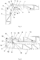
- the body 3 of the snapping part is pivotally connected to the middle portion of the inner side surface of the first side plate 11 by means of the third pin shaft 7, and extends out of the first conveying section 1 in the direction toward the second conveying section 2 (see Fig. 4 ).
- the first pin shaft 5 and the second pin shaft 6 are both fixed to the inner side surface of the second side plate 12 corresponding to the first side plate 11 provided with the snapping part.
- the first pin shaft 5 is located near the upper end of the second side plate 12, while the second pin shaft 6 is located near the lower end of the second side plate 12, and the second pin shaft 6 is farther away from the first conveying section 1 than the first pin shaft 5.
- the pivoting mechanism includes a second power mechanism 13, a link 14, and a side link 15.
- One end of the link 14 is pivotally connected to the outer side surface of the second side plate 12 by the first pin shaft 5. That is, the first pin shaft 5 is not only the pivot for pivotally connecting the link 14 to the second side plate 12, but also a fixture for fixing the first hook 8.
- One end of the side link 15 is pivotally connected to the outer side surface of the first side plate 11 by a fourth pin shaft 16; the other end of the link 14 and the second power mechanism 13 are pivotally connected to the other end of the side link 15 respectively (the pivotally connecting positions are different); the lower end of the first side plate 11 and the lower end of the second side plate 12 are pivotally connected through a fifth pin shaft 17.
- the second conveying section 2 can rotate about the first conveying section 1 with the driving of the second power mechanism 13, achieving the unfolding or folding of the second conveying section 2.
- the second power mechanism 13 employs an oil cylinder.
- the first power mechanism 4 is activated so that the piston rod thereof protrudes, pushing the snapping part to rotate about the third pin shaft 7 counterclockwise until the first hook 8 is hooked on the first pin shaft 5, thus, the second conveying section 2 is locked and the unfolding work of the second conveying section 2 is completed.
- the operation is very convenient, and the working efficiency is improved.
- the first power mechanism 4 When it is necessary for the second conveying section 2 to convert into the folded state from the unfolded state, firstly the first power mechanism 4 is activated so as to retract the piston rod thereof, driving the body 3 to rotate clockwise about the third pin shaft 7, so that the first hook 8 disconnects from the first pin shaft 5, and in this way the snapping part is in an unlocked position.
- the piston rod of the second power mechanism 13 extends out, pushing the side link 15 to rotate counterclockwise, and the side link 15 drives the rod 14 to push the second conveying section 2 to rotate with the fifth pin shaft 17 as the pivot until rotating to the state shown in Fig.
- the second conveying section 2 With the pivoting mechanism of the first conveying section 1 and the second conveying section 2, the second conveying section 2 can be held in the locked position even during the decompression of the oil cylinder as the first power mechanism 4 or during the replacement of the snapping part.
- the present invention enables the rapid and effective locking of the second conveying section 2 without the need for additional staff to wait for work near the material conveyor, and just one operator can complete such work on the driving platform, thereby, the production efficiency is improved, and the work intensity of workers is lowered.
- the first power mechanism 4 and the second power mechanism 13 according to the present invention can employ other power mechanisms in addition to employing the oil cylinders described in the above embodiments, as long as they can respectively drive the snapping part and the second conveying section 2 to pivot.
- the shape of the snapping part is not limited to the structure described above, for example, the body 3 may be a triangle, a rectangle and the like in addition to a fan shape. It is also feasible to remove the body 3 and fixedly connect one end of the first hook 8, one end of the second hook 9 and one end of the driving portion 10 together and pivotally connect them at one point.
- the body 3 is not limited to a sheet, but may have a certain thickness, such as a block shape.
- the present invention mainly utilizes a part having two hooks and two rod-like bodies (the first pin shaft 5 and the second pin shaft 6).
- the second conveying section 2 By hooking one hook and one rod-like body, the second conveying section 2 is fixed when the second conveying section 2 is unfolded, while by hooking the other hook with the other rod-like body, the second conveying section 2 is fixed when the second conveying section 2 is folded. So it is very convenient to fix when the second conveying section 2 is unfolded or folded, saving manpower and improving work efficiency.
- Each pin shaft (the first pin shaft 5, the second pin shaft 6, the third pin shaft 7, the fourth pin shaft 16 and the fifth pin shaft 17) mentioned in the present invention can be fixed by hinged connection, but it can also be fixed by welding.
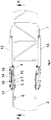
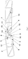
- the present invention also discloses a material conveyor, and as shown in Fig. 3 , the material conveyor includes the two above-mentioned locking devices for the material conveyor, wherein the two locking devices are symmetrically arranged on the material conveyor. Specifically, continuing with reference to Figs. 3 to 6 , the snapping part of one of the locking devices is pivotally connected to the inner side surface of one of the first side plates 11, while the snapping part of the other locking device is pivotally connected to the inner side surface of the other first side plate 11, and these two snapping parts are corresponding to each other.
- the first pin shaft 5 and the second pin shaft 6 of one of the locking devices are provided on the inner surface of one of the second side plates 12, while the first pin shaft 5 and the second pin shaft 6 of the other locking device are provided on the inner surface of the other second side plate 12.
- the first power mechanism 4 of one of the locking devices is provided on the first conveying section 1 and is located at the inside of one of the first side plates 11, while the first power mechanism 4 of the other locking device is provided on the first conveying section 1 and is located at the inside of the other first side plate 11, so that the first power mechanisms 4 of the two locking devices are both provided on the first conveying section 1 and are respectively near the two first side plates 11.
- the second power mechanisms 13 of the two pivoting mechanisms are located at the outside of the two first side plates 11 respectively, while both the link 14 and the side link 15 are located at the outside of the first side plate 11 and the second side plate 12, and the specific position relationship can be seen in Fig. 3 .
Landscapes
- Engineering & Computer Science (AREA)
- Mechanical Engineering (AREA)
- Framework For Endless Conveyors (AREA)
- Clamps And Clips (AREA)
Claims (7)
- Materialförderer, umfassend einen ersten Förderbereich (1), einen zweiten Förderbereich (2) und zwei Verriegelungsvorrichtungen für den Materialförderer, wobei beide der Verriegelungsvorrichtungen des Materialförderers an dem ersten Förderbereich (1) und dem zweiten Förderbereich (2) angeordnet sind, der an dem ersten Förderbereich (1) mittels eines Schwenkmechanismus gelenkig angeordnet ist, dadurch gekennzeichnet, dass jede Verriegelungsvorrichtung des Materialförderers umfasst:einen einrastenden Teil, der schwenkbar mit dem ersten Förderbereich (1) oder dem zweiten Förderbereich (2) verbunden und in der Lage ist, in eine Richtung zu schwenken, in die der zweite Förderbereich (2) schwenkt, wobei der einrastende Teil zwei Haken aufweist;eine erste Strebe und eine zweite Strebe, die an dem zweiten Förderbereich (2) oder dem ersten Förderbereich (1) bereitgestellt sind, mit dem der einrastende Teil nicht schwenkbar verbunden ist, und verwendet werden, mit den zwei Haken jeweils in geeigneter Weise derart einzuhaken, dass die relative Position des zweiten Förderbereichs (2) und des ersten Förderbereichs (1) fixiert ist, wenn der zweite Förderbereich (2) in Bezug auf den ersten Förderbereich (1) in einem eingeklappten oder ausgeklapptem Zustand ist; undeinen ersten Antriebsmechanismus (4) zum Antreiben des einrastenden Teils zum Schwenken.
- Materialförderer nach Anspruch 1, dadurch gekennzeichnet, dass das einrastende Teil ferner einen Körper (3) und einen Antriebsabschnitt (10) umfasst, wobei der Antriebsabschnitt (10) und die zwei Haken jeweils mit dem äußeren Umfang des Körpers (3) verbunden sind und über den äußeren Umfang hinausstehen, und der Körper (3) schwenkbar mit dem ersten Förderbereich (1) oder dem zweiten Förderbereich (2) verbunden ist;
der erste Antriebsmechanismus (4) ein Hydraulikölzylinder ist, wobei ein Ende davon an dem ersten Förderbereich (1) oder dem zweiten Förderbereich (2) fixiert ist und das andere Ende davon schwenkbar mit dem freien Ende des Antriebsabschnitts (10) verbunden ist. - Materialförderer nach Anspruch 2, dadurch gekennzeichnet, dass der Körper (3) fächerförmig ist, und die zwei Haken jeweils mit den zwei Enden des Bogens der Fächerform verbunden sind, wobei der Antriebsabschnitt (10) eine Verbindungselementform aufweist und ein Ende davon an dem Winkelbogen der Fächerform verbunden ist, und sich die zwei Haken und der Antriebsabschnitt (10) alle in derselben Ebene wie der Körper (3) befinden.
- Materialförderer nach Anspruch 3, dadurch gekennzeichnet, dass das Ende des ersten Förderbereichs (1) gegenüber des zweiten Förderbereichs (2) mit zwei sich gegenüberliegenden ersten Seitenplatten (11) versehen ist, und das Ende des zweiten Förderbereichs (2) gegenüber des ersten Förderbereichs (1) mit zwei sich gegenüberliegenden zweiten Seitenplatten (12) versehen ist;
der Körper (3) des einrastenden Teils schwenkbar mit dem mittleren Abschnitt der Innenseitenfläche der ersten Seitenplatte (11) verbunden ist und sich aus dem ersten Förderbereich (1) in der Richtung hin zu dem zweiten Förderbereich (2) erstreckt, wobei die erste Strebe und die zweite Strebe beide an der Innenseitenfläche der zweiten Seitenplatte (12) entsprechend zu der mit dem einrastenden Teil versehenen ersten Seitenplatte (11) fixiert sind, sodass die zwei Haken sicher mit der ersten Strebe bzw. der zweiten Strebe einhaken, wenn der zweite Förderbereich (2) eingeklappt oder ausgeklappt ist;
ein Ende des Hydraulikölzylinders an dem ersten Förderbereich (1) fixiert ist. - Materialförderer nach Anspruch 3, dadurch gekennzeichnet, dass das Ende des ersten Förderbereichs (1) gegenüber des zweiten Förderbereichs (2) mit zwei sich gegenüberliegenden ersten Seitenplatten (11) versehen ist, und das Ende des zweiten Förderbereichs (2) gegenüber des ersten Förderbereichs (1) mit zwei sich gegenüberliegenden zweiten Seitenplatten (12) versehen ist;
der Körper (3) des einrastenden Teils schwenkbar mit dem mittleren Abschnitt der Innenseitenfläche der zweiten Seitenplatte (12) verbunden ist, und sich aus dem zweiten Förderbereich (2) in der Richtung hin zu dem ersten Förderbereich (1) erstreckt, wobei die erste Strebe und die zweite Strebe beide an der Innenseitenfläche der ersten Seitenplatte (11) entsprechend zu der mit dem einrastenden Teil versehenen zweiten Seitenplatte (12) fixiert sind, sodass die zwei Haken sicher mit der ersten Strebe bzw. der zweiten Strebe einhaken, wenn der zweite Förderbereich (2) eingeklappt oder ausgeklappt ist;
ein Ende des Hydraulikölzylinders an dem zweiten Förderbereich (2) fixiert ist. - Materialförderer nach Anspruch 4, dadurch gekennzeichnet, dass der Schwenkmechanismus einen zweiten Antriebsmechanismus (13), ein Verbindungselement (14) und ein Seitenverbindungselement (15) umfasst, und die erste Strebe der erste Bolzenschaft (5) ist;
ein Ende des Verbindungselements (14) durch den ersten Bolzenschaft (5) schwenkbar mit der Außenseitenfläche der zweiten Seitenplatte (12) verbunden ist; ein Ende des Seitenverbindungselements (15) schwenkbar mit der Außenseitenfläche der ersten Seitenplatte (11) entsprechend zu der schwenkbar mit dem Verbindungselement (14) verbundenen zweiten Seitenplatte (12) verbunden ist; das andere Ende des Verbindungselements (14) und der zweite Antriebsmechanismus (13) jeweils schwenkbar mit dem anderen Ende des Seitenverbindungselements (15) verbunden sind; das untere Ende der ersten Seitenplatte (11) schwenkbar mit dem unteren Ende der zweiten Seitenplatte (12) verbunden ist. - Materialförderer nach Anspruch 6, dadurch gekennzeichnet, dass in einem ausgeklapptem Zustand sich der erste Bolzenschaft (5) in der Nähe des oberen Endes der zweiten Seitenplatte (12) befindet, während sich die zweite Strebe in der Nähe des unteren Endes der zweiten Seitenplatte (12) befindet, und sich die zweite Strebe weiter weg von dem ersten Förderbereich (1) als der erste Bolzenschaft (5) befindet.
Applications Claiming Priority (2)
| Application Number | Priority Date | Filing Date | Title |
|---|---|---|---|
| CN201410498420.7A CN104213498B (zh) | 2014-09-25 | 2014-09-25 | 用于输料机的锁定装置及其输料机 |
| PCT/CN2014/092283 WO2016045187A1 (zh) | 2014-09-25 | 2014-11-26 | 用于输料机的锁定装置及其输料机 |
Publications (3)
| Publication Number | Publication Date |
|---|---|
| EP3199705A1 EP3199705A1 (de) | 2017-08-02 |
| EP3199705A4 EP3199705A4 (de) | 2018-05-23 |
| EP3199705B1 true EP3199705B1 (de) | 2019-07-10 |
Family
ID=52095381
Family Applications (1)
| Application Number | Title | Priority Date | Filing Date |
|---|---|---|---|
| EP14902325.1A Active EP3199705B1 (de) | 2014-09-25 | 2014-11-26 | Materialförderer |
Country Status (4)
| Country | Link |
|---|---|
| US (1) | US9828183B2 (de) |
| EP (1) | EP3199705B1 (de) |
| CN (1) | CN104213498B (de) |
| WO (1) | WO2016045187A1 (de) |
Families Citing this family (14)
| Publication number | Priority date | Publication date | Assignee | Title |
|---|---|---|---|---|
| CN106005896A (zh) * | 2016-06-30 | 2016-10-12 | 柳州市奥火工程机械有限公司 | 折叠输送带 |
| CN106378445A (zh) * | 2016-10-08 | 2017-02-08 | 江苏国能合金科技有限公司 | 一种非晶薄带设备车架锁定装置 |
| GB2562803B (en) | 2017-05-26 | 2020-02-05 | Terex Gb Ltd | Telescopic conveyor with pivoted camber means |
| US10370193B2 (en) | 2017-11-13 | 2019-08-06 | Caterpillar Paving Products Inc. | Folding conveyer for a construction machine |
| CN108128597B (zh) * | 2018-01-10 | 2024-03-15 | 江苏徐工工程机械研究院有限公司 | 折叠、卸料高度调节和皮带张紧的装置及带式输送机 |
| CN108974790A (zh) * | 2018-08-02 | 2018-12-11 | 嘉鹏再升科技(深圳)股份有限公司 | 一种折叠式的散料提料装置 |
| CN109183559A (zh) * | 2018-08-02 | 2019-01-11 | 嘉鹏再升科技(深圳)股份有限公司 | 一种连续移动式施工的就地热再生设备 |
| CN108928599B (zh) * | 2018-08-09 | 2023-10-27 | 华南新海(深圳)科技股份有限公司 | 折叠式过道输送机 |
| CN110027891A (zh) * | 2019-05-21 | 2019-07-19 | 三一汽车制造有限公司 | 输料机构及铣刨机 |
| US11142876B2 (en) * | 2019-10-31 | 2021-10-12 | Caterpillar Paving Products Inc. | Articulating conveyor support for a cold planer |
| CN111268403B (zh) * | 2020-04-03 | 2024-03-01 | 上海微松工业自动化有限公司 | 一种物料精确定位的分料装置及其分料方法 |
| CN111472245B (zh) * | 2020-04-29 | 2021-07-27 | 唐山大成路桥有限公司 | 一种输送装置可折叠的铣刨机 |
| CN114056882B (zh) * | 2021-12-13 | 2026-04-21 | 山东路得威工程机械制造有限公司 | 一种用于折叠机构的锁定装置及输料机 |
| CN115211353A (zh) * | 2022-06-09 | 2022-10-21 | 辽宁华胜环保科技有限公司 | 多段自动折叠喷洒系统 |
Family Cites Families (22)
| Publication number | Priority date | Publication date | Assignee | Title |
|---|---|---|---|---|
| US2649177A (en) * | 1951-03-12 | 1953-08-18 | Mathews Conveyer Co | Universal coupling for conveyers |
| US2604201A (en) * | 1951-08-06 | 1952-07-22 | Goodman Mfg Co | Conveyer swivel joint |
| DE2228395B2 (de) | 1972-06-10 | 1974-07-18 | Vereinigte Flugtechnische Werkefokker Gmbh, 2800 Bremen | Bordeigenes Frachtbe- und -Entladegerät für Flugzeuge |
| US4390094A (en) * | 1981-02-18 | 1983-06-28 | Sperry Corporation | Automatic latch for unloading auger |
| US4427105A (en) * | 1981-09-18 | 1984-01-24 | Parham Industries, Inc. | Auger casing latching mechanism |
| CA2119094C (en) | 1993-03-16 | 2005-09-13 | Michael J. Pettijohn | Mobile hydraulic conveyor |
| US5662210A (en) * | 1996-03-21 | 1997-09-02 | Commercial Welding Ltd. | Folding apparatus for transporting particulate material |
| US6910586B2 (en) * | 2003-03-19 | 2005-06-28 | Mccloskey James Paschal | System and method for folding conveyors |
| WO2006088349A1 (en) * | 2005-02-18 | 2006-08-24 | Superior Highwall Miners, Inc. | Conveyor segment and assembly for use in high wall mining, and coupling and releasing methods |
| US7347311B2 (en) * | 2006-06-07 | 2008-03-25 | Volvo Construction Equipment Ab | Folding mechanism for road machinery foldable conveyors |
| WO2009111628A1 (en) * | 2008-03-05 | 2009-09-11 | Earth Corp. Industries, Llc | Reload conveyor with articulating conveyor frame |
| US8359695B2 (en) * | 2008-04-24 | 2013-01-29 | 9089-1557 Quebec Inc. (Entretien De Stationnement M.A.) | Mechanical sweeper |
| DE102008021484B4 (de) * | 2008-04-29 | 2010-01-28 | Wirtgen Gmbh | Knickbares Transportband für eine Baumaschine, selbstfahrende Baumaschine und Verfahren zum Verschwenken eines Transportbandes |
| CN201411625Y (zh) * | 2009-06-12 | 2010-02-24 | 沈阳北方交通重工有限公司 | 一种为铣刨机输送废料的折叠式输送机的折叠机构 |
| CN102372152A (zh) | 2010-08-25 | 2012-03-14 | 施汉冲 | 一种折叠式卸料胶带机 |
| CN202139526U (zh) | 2011-05-26 | 2012-02-08 | 三一重工股份有限公司 | 铣刨机输料折叠控制系统及铣刨机 |
| CN102409601A (zh) * | 2011-09-19 | 2012-04-11 | 徐州徐工筑路机械有限公司 | 一种铣刨机用折叠式输送装置 |
| CN102518031B (zh) * | 2012-01-04 | 2014-10-15 | 三一重工股份有限公司 | 铣刨机二级输料机折叠系统及铣刨机 |
| US8881887B2 (en) * | 2012-06-14 | 2014-11-11 | Caterpillar Inc. | Foldable conveyor |
| CN103243631A (zh) * | 2013-04-16 | 2013-08-14 | 广西柳工机械股份有限公司 | 铣刨机输料架单油缸折叠机构 |
| CN203429545U (zh) * | 2013-09-05 | 2014-02-12 | 中联重科股份有限公司 | 铣刨机输料装置液压控制系统 |
| CN204112196U (zh) * | 2014-09-25 | 2015-01-21 | 戴纳派克(中国)压实摊铺设备有限公司 | 用于输料机的锁定装置及其输料机 |
-
2014
- 2014-09-25 CN CN201410498420.7A patent/CN104213498B/zh active Active
- 2014-11-26 WO PCT/CN2014/092283 patent/WO2016045187A1/zh not_active Ceased
- 2014-11-26 EP EP14902325.1A patent/EP3199705B1/de active Active
- 2014-11-26 US US15/514,071 patent/US9828183B2/en active Active
Non-Patent Citations (1)
| Title |
|---|
| None * |
Also Published As
| Publication number | Publication date |
|---|---|
| EP3199705A4 (de) | 2018-05-23 |
| WO2016045187A1 (zh) | 2016-03-31 |
| US20170305675A1 (en) | 2017-10-26 |
| CN104213498A (zh) | 2014-12-17 |
| CN104213498B (zh) | 2016-04-27 |
| US9828183B2 (en) | 2017-11-28 |
| EP3199705A1 (de) | 2017-08-02 |
Similar Documents
| Publication | Publication Date | Title |
|---|---|---|
| EP3199705B1 (de) | Materialförderer | |
| AU2013254927B2 (en) | Folding mechanism | |
| CN209398433U (zh) | 多功能拱架台车 | |
| PL246521B1 (pl) | Urządzenie do kontroli bezpieczeństwa i sposób jego przemieszczania | |
| CN106639873A (zh) | 一种多功能剪叉撑平台钻机 | |
| BR112016004868B1 (pt) | Unidade de processamento de material mineral e método para operar uma unidade de processamento de material mineral | |
| CN204283263U (zh) | 一种铁钻工 | |
| CN114505829B (zh) | 液压油缸翻身辅助装置 | |
| CN102452616A (zh) | 一种支腿支撑装置及移动式起重机 | |
| CN209398437U (zh) | 一种多功能支护机械手的夹具 | |
| AU2006274471A1 (en) | Folding boom | |
| CN201845080U (zh) | 分离式阵面、馈源自动展开对准装置 | |
| KR101559766B1 (ko) | 붐대 회전 장치와 그를 적용한 고소작업 시스템 및 고소 작업차 | |
| CN102991477B (zh) | 工程机械及其支腿装置 | |
| CN110318785A (zh) | 一种基于隧道机械化全断面开挖的钢架及其施工方法 | |
| CN204112196U (zh) | 用于输料机的锁定装置及其输料机 | |
| CN210885040U (zh) | 摆动支腿及工程机械设备 | |
| CN205057987U (zh) | Pdc钻头清理维修工作台 | |
| CN102900363B (zh) | 履带底盘、旋挖钻机和该履带底盘的运输方法 | |
| CN217976238U (zh) | 基于三臂拱架安装台车的钢架快速安装铰接装置 | |
| KR101681801B1 (ko) | 확장된 작업 반경을 갖는 붐대 회전 장치와 그를 적용한 고소작업 시스템 및 고소 작업차 | |
| CN102491202B (zh) | 行车式起重机 | |
| CN106006410B (zh) | 一种适用于小型吊机中的可伸缩可旋转可折叠式支腿装置 | |
| CN102489981B (zh) | 用于安装或拆卸零部件的辅助装置 | |
| CN206318652U (zh) | 支腿桁架臂起重机 |
Legal Events
| Date | Code | Title | Description |
|---|---|---|---|
| STAA | Information on the status of an ep patent application or granted ep patent |
Free format text: STATUS: THE INTERNATIONAL PUBLICATION HAS BEEN MADE |
|
| PUAI | Public reference made under article 153(3) epc to a published international application that has entered the european phase |
Free format text: ORIGINAL CODE: 0009012 |
|
| STAA | Information on the status of an ep patent application or granted ep patent |
Free format text: STATUS: REQUEST FOR EXAMINATION WAS MADE |
|
| 17P | Request for examination filed |
Effective date: 20170421 |
|
| AK | Designated contracting states |
Kind code of ref document: A1 Designated state(s): AL AT BE BG CH CY CZ DE DK EE ES FI FR GB GR HR HU IE IS IT LI LT LU LV MC MK MT NL NO PL PT RO RS SE SI SK SM TR |
|
| AX | Request for extension of the european patent |
Extension state: BA ME |
|
| DAX | Request for extension of the european patent (deleted) | ||
| REG | Reference to a national code |
Ref country code: DE Ref legal event code: R079 Ref document number: 602014050013 Country of ref document: DE Free format text: PREVIOUS MAIN CLASS: E01C0023088000 Ipc: B65G0021100000 |
|
| A4 | Supplementary search report drawn up and despatched |
Effective date: 20180424 |
|
| RIC1 | Information provided on ipc code assigned before grant |
Ipc: B65G 41/00 20060101ALI20180419BHEP Ipc: B65G 21/10 20060101AFI20180419BHEP Ipc: E01C 23/12 20060101ALI20180419BHEP Ipc: E01C 23/088 20060101ALI20180419BHEP |
|
| STAA | Information on the status of an ep patent application or granted ep patent |
Free format text: STATUS: EXAMINATION IS IN PROGRESS |
|
| 17Q | First examination report despatched |
Effective date: 20181130 |
|
| GRAP | Despatch of communication of intention to grant a patent |
Free format text: ORIGINAL CODE: EPIDOSNIGR1 |
|
| STAA | Information on the status of an ep patent application or granted ep patent |
Free format text: STATUS: GRANT OF PATENT IS INTENDED |
|
| INTG | Intention to grant announced |
Effective date: 20190108 |
|
| GRAS | Grant fee paid |
Free format text: ORIGINAL CODE: EPIDOSNIGR3 |
|
| GRAA | (expected) grant |
Free format text: ORIGINAL CODE: 0009210 |
|
| STAA | Information on the status of an ep patent application or granted ep patent |
Free format text: STATUS: THE PATENT HAS BEEN GRANTED |
|
| AK | Designated contracting states |
Kind code of ref document: B1 Designated state(s): AL AT BE BG CH CY CZ DE DK EE ES FI FR GB GR HR HU IE IS IT LI LT LU LV MC MK MT NL NO PL PT RO RS SE SI SK SM TR |
|
| REG | Reference to a national code |
Ref country code: GB Ref legal event code: FG4D |
|
| REG | Reference to a national code |
Ref country code: CH Ref legal event code: EP Ref country code: AT Ref legal event code: REF Ref document number: 1153353 Country of ref document: AT Kind code of ref document: T Effective date: 20190715 |
|
| REG | Reference to a national code |
Ref country code: DE Ref legal event code: R096 Ref document number: 602014050013 Country of ref document: DE |
|
| REG | Reference to a national code |
Ref country code: IE Ref legal event code: FG4D |
|
| REG | Reference to a national code |
Ref country code: NL Ref legal event code: MP Effective date: 20190710 |
|
| REG | Reference to a national code |
Ref country code: LT Ref legal event code: MG4D |
|
| REG | Reference to a national code |
Ref country code: AT Ref legal event code: MK05 Ref document number: 1153353 Country of ref document: AT Kind code of ref document: T Effective date: 20190710 |
|
| PG25 | Lapsed in a contracting state [announced via postgrant information from national office to epo] |
Ref country code: FI Free format text: LAPSE BECAUSE OF FAILURE TO SUBMIT A TRANSLATION OF THE DESCRIPTION OR TO PAY THE FEE WITHIN THE PRESCRIBED TIME-LIMIT Effective date: 20190710 Ref country code: NO Free format text: LAPSE BECAUSE OF FAILURE TO SUBMIT A TRANSLATION OF THE DESCRIPTION OR TO PAY THE FEE WITHIN THE PRESCRIBED TIME-LIMIT Effective date: 20191010 Ref country code: NL Free format text: LAPSE BECAUSE OF FAILURE TO SUBMIT A TRANSLATION OF THE DESCRIPTION OR TO PAY THE FEE WITHIN THE PRESCRIBED TIME-LIMIT Effective date: 20190710 Ref country code: AT Free format text: LAPSE BECAUSE OF FAILURE TO SUBMIT A TRANSLATION OF THE DESCRIPTION OR TO PAY THE FEE WITHIN THE PRESCRIBED TIME-LIMIT Effective date: 20190710 Ref country code: HR Free format text: LAPSE BECAUSE OF FAILURE TO SUBMIT A TRANSLATION OF THE DESCRIPTION OR TO PAY THE FEE WITHIN THE PRESCRIBED TIME-LIMIT Effective date: 20190710 Ref country code: LT Free format text: LAPSE BECAUSE OF FAILURE TO SUBMIT A TRANSLATION OF THE DESCRIPTION OR TO PAY THE FEE WITHIN THE PRESCRIBED TIME-LIMIT Effective date: 20190710 Ref country code: SE Free format text: LAPSE BECAUSE OF FAILURE TO SUBMIT A TRANSLATION OF THE DESCRIPTION OR TO PAY THE FEE WITHIN THE PRESCRIBED TIME-LIMIT Effective date: 20190710 Ref country code: PT Free format text: LAPSE BECAUSE OF FAILURE TO SUBMIT A TRANSLATION OF THE DESCRIPTION OR TO PAY THE FEE WITHIN THE PRESCRIBED TIME-LIMIT Effective date: 20191111 Ref country code: BG Free format text: LAPSE BECAUSE OF FAILURE TO SUBMIT A TRANSLATION OF THE DESCRIPTION OR TO PAY THE FEE WITHIN THE PRESCRIBED TIME-LIMIT Effective date: 20191010 |
|
| PG25 | Lapsed in a contracting state [announced via postgrant information from national office to epo] |
Ref country code: AL Free format text: LAPSE BECAUSE OF FAILURE TO SUBMIT A TRANSLATION OF THE DESCRIPTION OR TO PAY THE FEE WITHIN THE PRESCRIBED TIME-LIMIT Effective date: 20190710 Ref country code: GR Free format text: LAPSE BECAUSE OF FAILURE TO SUBMIT A TRANSLATION OF THE DESCRIPTION OR TO PAY THE FEE WITHIN THE PRESCRIBED TIME-LIMIT Effective date: 20191011 Ref country code: RS Free format text: LAPSE BECAUSE OF FAILURE TO SUBMIT A TRANSLATION OF THE DESCRIPTION OR TO PAY THE FEE WITHIN THE PRESCRIBED TIME-LIMIT Effective date: 20190710 Ref country code: LV Free format text: LAPSE BECAUSE OF FAILURE TO SUBMIT A TRANSLATION OF THE DESCRIPTION OR TO PAY THE FEE WITHIN THE PRESCRIBED TIME-LIMIT Effective date: 20190710 Ref country code: IS Free format text: LAPSE BECAUSE OF FAILURE TO SUBMIT A TRANSLATION OF THE DESCRIPTION OR TO PAY THE FEE WITHIN THE PRESCRIBED TIME-LIMIT Effective date: 20191110 Ref country code: ES Free format text: LAPSE BECAUSE OF FAILURE TO SUBMIT A TRANSLATION OF THE DESCRIPTION OR TO PAY THE FEE WITHIN THE PRESCRIBED TIME-LIMIT Effective date: 20190710 |
|
| PG25 | Lapsed in a contracting state [announced via postgrant information from national office to epo] |
Ref country code: TR Free format text: LAPSE BECAUSE OF FAILURE TO SUBMIT A TRANSLATION OF THE DESCRIPTION OR TO PAY THE FEE WITHIN THE PRESCRIBED TIME-LIMIT Effective date: 20190710 |
|
| PG25 | Lapsed in a contracting state [announced via postgrant information from national office to epo] |
Ref country code: IT Free format text: LAPSE BECAUSE OF FAILURE TO SUBMIT A TRANSLATION OF THE DESCRIPTION OR TO PAY THE FEE WITHIN THE PRESCRIBED TIME-LIMIT Effective date: 20190710 Ref country code: PL Free format text: LAPSE BECAUSE OF FAILURE TO SUBMIT A TRANSLATION OF THE DESCRIPTION OR TO PAY THE FEE WITHIN THE PRESCRIBED TIME-LIMIT Effective date: 20190710 Ref country code: DK Free format text: LAPSE BECAUSE OF FAILURE TO SUBMIT A TRANSLATION OF THE DESCRIPTION OR TO PAY THE FEE WITHIN THE PRESCRIBED TIME-LIMIT Effective date: 20190710 Ref country code: EE Free format text: LAPSE BECAUSE OF FAILURE TO SUBMIT A TRANSLATION OF THE DESCRIPTION OR TO PAY THE FEE WITHIN THE PRESCRIBED TIME-LIMIT Effective date: 20190710 Ref country code: RO Free format text: LAPSE BECAUSE OF FAILURE TO SUBMIT A TRANSLATION OF THE DESCRIPTION OR TO PAY THE FEE WITHIN THE PRESCRIBED TIME-LIMIT Effective date: 20190710 |
|
| PG25 | Lapsed in a contracting state [announced via postgrant information from national office to epo] |
Ref country code: CZ Free format text: LAPSE BECAUSE OF FAILURE TO SUBMIT A TRANSLATION OF THE DESCRIPTION OR TO PAY THE FEE WITHIN THE PRESCRIBED TIME-LIMIT Effective date: 20190710 Ref country code: IS Free format text: LAPSE BECAUSE OF FAILURE TO SUBMIT A TRANSLATION OF THE DESCRIPTION OR TO PAY THE FEE WITHIN THE PRESCRIBED TIME-LIMIT Effective date: 20200224 Ref country code: SM Free format text: LAPSE BECAUSE OF FAILURE TO SUBMIT A TRANSLATION OF THE DESCRIPTION OR TO PAY THE FEE WITHIN THE PRESCRIBED TIME-LIMIT Effective date: 20190710 Ref country code: SK Free format text: LAPSE BECAUSE OF FAILURE TO SUBMIT A TRANSLATION OF THE DESCRIPTION OR TO PAY THE FEE WITHIN THE PRESCRIBED TIME-LIMIT Effective date: 20190710 |
|
| REG | Reference to a national code |
Ref country code: DE Ref legal event code: R097 Ref document number: 602014050013 Country of ref document: DE |
|
| REG | Reference to a national code |
Ref country code: CH Ref legal event code: PL |
|
| PLBE | No opposition filed within time limit |
Free format text: ORIGINAL CODE: 0009261 |
|
| STAA | Information on the status of an ep patent application or granted ep patent |
Free format text: STATUS: NO OPPOSITION FILED WITHIN TIME LIMIT |
|
| PG2D | Information on lapse in contracting state deleted |
Ref country code: IS |
|
| PG25 | Lapsed in a contracting state [announced via postgrant information from national office to epo] |
Ref country code: LU Free format text: LAPSE BECAUSE OF NON-PAYMENT OF DUE FEES Effective date: 20191126 Ref country code: LI Free format text: LAPSE BECAUSE OF NON-PAYMENT OF DUE FEES Effective date: 20191130 Ref country code: CH Free format text: LAPSE BECAUSE OF NON-PAYMENT OF DUE FEES Effective date: 20191130 Ref country code: MC Free format text: LAPSE BECAUSE OF FAILURE TO SUBMIT A TRANSLATION OF THE DESCRIPTION OR TO PAY THE FEE WITHIN THE PRESCRIBED TIME-LIMIT Effective date: 20190710 |
|
| 26N | No opposition filed |
Effective date: 20200603 |
|
| REG | Reference to a national code |
Ref country code: BE Ref legal event code: MM Effective date: 20191130 |
|
| PG25 | Lapsed in a contracting state [announced via postgrant information from national office to epo] |
Ref country code: SI Free format text: LAPSE BECAUSE OF FAILURE TO SUBMIT A TRANSLATION OF THE DESCRIPTION OR TO PAY THE FEE WITHIN THE PRESCRIBED TIME-LIMIT Effective date: 20190710 |
|
| GBPC | Gb: european patent ceased through non-payment of renewal fee |
Effective date: 20191126 |
|
| PG25 | Lapsed in a contracting state [announced via postgrant information from national office to epo] |
Ref country code: IE Free format text: LAPSE BECAUSE OF NON-PAYMENT OF DUE FEES Effective date: 20191126 Ref country code: FR Free format text: LAPSE BECAUSE OF NON-PAYMENT OF DUE FEES Effective date: 20191130 Ref country code: GB Free format text: LAPSE BECAUSE OF NON-PAYMENT OF DUE FEES Effective date: 20191126 |
|
| PG25 | Lapsed in a contracting state [announced via postgrant information from national office to epo] |
Ref country code: BE Free format text: LAPSE BECAUSE OF NON-PAYMENT OF DUE FEES Effective date: 20191130 |
|
| PG25 | Lapsed in a contracting state [announced via postgrant information from national office to epo] |
Ref country code: CY Free format text: LAPSE BECAUSE OF FAILURE TO SUBMIT A TRANSLATION OF THE DESCRIPTION OR TO PAY THE FEE WITHIN THE PRESCRIBED TIME-LIMIT Effective date: 20190710 |
|
| PG25 | Lapsed in a contracting state [announced via postgrant information from national office to epo] |
Ref country code: MT Free format text: LAPSE BECAUSE OF FAILURE TO SUBMIT A TRANSLATION OF THE DESCRIPTION OR TO PAY THE FEE WITHIN THE PRESCRIBED TIME-LIMIT Effective date: 20190710 Ref country code: HU Free format text: LAPSE BECAUSE OF FAILURE TO SUBMIT A TRANSLATION OF THE DESCRIPTION OR TO PAY THE FEE WITHIN THE PRESCRIBED TIME-LIMIT; INVALID AB INITIO Effective date: 20141126 |
|
| PG25 | Lapsed in a contracting state [announced via postgrant information from national office to epo] |
Ref country code: MK Free format text: LAPSE BECAUSE OF FAILURE TO SUBMIT A TRANSLATION OF THE DESCRIPTION OR TO PAY THE FEE WITHIN THE PRESCRIBED TIME-LIMIT Effective date: 20190710 |
|
| P01 | Opt-out of the competence of the unified patent court (upc) registered |
Effective date: 20230529 |
|
| PGFP | Annual fee paid to national office [announced via postgrant information from national office to epo] |
Ref country code: DE Payment date: 20251118 Year of fee payment: 12 |