US7347311B2 - Folding mechanism for road machinery foldable conveyors - Google Patents
Folding mechanism for road machinery foldable conveyors Download PDFInfo
- Publication number
- US7347311B2 US7347311B2 US11/448,941 US44894106A US7347311B2 US 7347311 B2 US7347311 B2 US 7347311B2 US 44894106 A US44894106 A US 44894106A US 7347311 B2 US7347311 B2 US 7347311B2
- Authority
- US
- United States
- Prior art keywords
- conveyor
- linkage
- actuator
- link
- drive link
- Prior art date
- Legal status (The legal status is an assumption and is not a legal conclusion. Google has not performed a legal analysis and makes no representation as to the accuracy of the status listed.)
- Active, expires
Links
Images


Classifications
-
- B—PERFORMING OPERATIONS; TRANSPORTING
- B65—CONVEYING; PACKING; STORING; HANDLING THIN OR FILAMENTARY MATERIAL
- B65G—TRANSPORT OR STORAGE DEVICES, e.g. CONVEYORS FOR LOADING OR TIPPING, SHOP CONVEYOR SYSTEMS OR PNEUMATIC TUBE CONVEYORS
- B65G21/00—Supporting or protective framework or housings for endless load-carriers or traction elements of belt or chain conveyors
- B65G21/10—Supporting or protective framework or housings for endless load-carriers or traction elements of belt or chain conveyors movable, or having interchangeable or relatively movable parts; Devices for moving framework or parts thereof
- B65G21/14—Supporting or protective framework or housings for endless load-carriers or traction elements of belt or chain conveyors movable, or having interchangeable or relatively movable parts; Devices for moving framework or parts thereof to allow adjustment of length or configuration of load-carrier or traction element
-
- B—PERFORMING OPERATIONS; TRANSPORTING
- B65—CONVEYING; PACKING; STORING; HANDLING THIN OR FILAMENTARY MATERIAL
- B65G—TRANSPORT OR STORAGE DEVICES, e.g. CONVEYORS FOR LOADING OR TIPPING, SHOP CONVEYOR SYSTEMS OR PNEUMATIC TUBE CONVEYORS
- B65G41/00—Supporting frames or bases for conveyors as a whole, e.g. transportable conveyor frames
- B65G41/001—Supporting frames or bases for conveyors as a whole, e.g. transportable conveyor frames with the conveyor adjustably mounted on the supporting frame or base
- B65G41/002—Pivotably mounted
Definitions
- the present invention relates to road construction vehicles, and more particularly to a foldable material transport conveyor for such vehicles.
- One type of road construction vehicle commonly referred to as a milling machine, generally includes a mainframe, a cutting drum rotatably mounted to the frame for removing such as asphalt from a roadbed, and a conveyor.
- the conveyor is used to transport the material cuttings to a truck bed or other collection apparatus.
- these conveyors are foldable to facilitate transport between job sites, usually by folding an outer conveyor section beneath an inner conveyor section that is attached to the main frame.
- the present invention is a folding mechanism for a vehicle conveyor having a longitudinal axis generally along which the conveyor transports materials and including inner and outer sections and a joint pivotally connecting the inner and outer sections.
- Each one of the conveyor inner and outer sections has first and second ends and a centerline extending between the two ends.
- the inner section is connectable with a vehicle and the inner section centerline is generally collinear with the conveyor axis.
- the conveyor outer section is pivotable about the joint between a deployed position, at which the centerlines of the inner and outer conveyor sections are generally collinear and both centerlines extend generally along the conveyor axis, and a folded position at which the conveyor outer section is disposed generally above the conveyor inner section.
- the folding mechanism comprises a linkage configured to displace the conveyor outer section between the deployed and folded position.
- the linkage includes a drive link having a first end pivotably connected with the conveyor inner section, an opposing second end, and a centerline extending between the first and second ends.
- a connector link has a first end pivotably connected with the drive link, a second end pivotably connected with the conveyor outer section, and a centerline extending between the connector link first and second ends.
- the linkage is moveable between a first limit position at which the conveyor outer section is located in the deployed position, the drive link centerline extends generally parallel to the conveyor axis and the connector link centerline extends generally perpendicular to the conveyor axis, and a second limit position. At the second limit position, the conveyor outer section is located in the folded position, the drive link centerline extends generally perpendicular to the conveyor axis, and the connector link centerline extends generally parallel to and is spaced above the conveyor axis.
- the present invention is again a folding mechanism for a conveyor as described above.
- the folding mechanism comprises a linkage configured to displace the conveyor outer section between the deployed and folded positions.
- the linkage includes a drive link having a first end pivotably connected with the conveyor inner section and an opposing second end, and a connector link having a first end pivotably connected with the drive link and a second end pivotably connected with the conveyor outer section.
- the linkage is moveable between a first limit position, at which the conveyor outer section is located in the deployed position, and a second limit position at which the conveyor outer section is located in the folded position.
- an actuator is mounted on the conveyor inner section, configured to displace the linkage between the first and second limit positions, and has a movable member connected with the drive link.
- the actuator movable member is displaceable between a first position, at which the linkage is located at the first limit position, and a second position at which the linkage is located at the second limit position.
- At least one of the actuator and the linkage is configured such that the folding mechanism exerts on the conveyor outer section a first moment about the joint axis when the actuator member displaces from the actuator first position toward the member second position.
- the folding mechanism exerts on the conveyor outer section a second moment about the joint axis when the actuator member displaces from the actuator second position toward the first position.
- the magnitude of the first moment is generally equal to the magnitude of the second moment.
- the present invention is again a folding mechanism for a vehicle conveyor, the conveyor being as generally described above and further having inner and outer conveyor sections with upper and lower surfaces extending generally between the two ends thereof.
- the folding mechanism comprises a linkage configured to displace the conveyor outer section between the deployed and folded positions.
- the linkage includes a drive link having a first end pivotally connected with the conveyor inner section, an opposing second end, and a centerline extending between the first and second ends.
- a connector link has a first end pivotally connected with the drive link, a second end pivotally connected with the conveyor outer section, and a centerline extending between the connector link first and second ends.
- the linkage is moveable between a first limit position, at which the conveyor outer section is located in the deployed position, and a second limit position at which the conveyor outer section is located in the folded position.
- an actuator is mounted on the conveyor inner section, is operatively connected with the drive link, and is configured to angularly displace the drive link about an axis extending through the drive link first end so as to move the linkage between the first and second limit positions.
- the actuator and folding linkage are arranged on the inner and outer conveyor sections such that each one of the actuator, the drive link and the connector link remains spaced generally above the lower surface of the conveyor inner section when the linkage moves between the first and second limit positions.
- the present invention is again a folding mechanism for a conveyor as described above.
- the folding mechanism comprises a linkage configured to displace the conveyor outer section between the deployed and folded positions.
- the linkage includes a drive link having a first end pivotally connected with the conveyor inner section, an opposing second end, and a centerline extending between the first and second ends and a connector link having a first end connected with the drive link, a second end connected with the conveyor outer section, and a centerline extending between the first and second ends.
- the linkage is moveable between a first limit position, at which the conveyor outer section is located in the deployed position, and a second limit position at which the conveyor outer section is located in the folded position.
- An actuator is coupled with the conveyor inner section and has a moveable member linearly displaceable along an axis, the actuator axis extending generally parallel to the conveyor inner section centerline.
- the actuator moveable member is coupled with the drive link such that displacement of the member along the axis moves the linkage between the first limit position, at which the drive link centerline extends generally parallel to and spaced below the actuator axis and the connector link centerline extends generally perpendicular to the actuator axis, and the second limit position.
- the drive link centerline extends generally perpendicular to the actuator axis and the connector link centerline extends generally parallel to and spaced above the actuator axis.
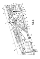
- FIG. 1 is a partly broken-away, side elevational view of a conveyor having a folding mechanism in accordance with the present invention, shown mounted to a road milling machine and in a deployed position;
- FIG. 2 is another view of the conveyor of FIG. 1 , shown in a folded position;
- FIGS. 3A-3C are each an enlarged, broken-away view of the conveyor and folding mechanism, showing an actuator and a single folding mechanism with the conveyor outer section in the deployed position, an intermediate position, and the folded position, respectively;
- FIGS. 4A-4I are each a broken-away, side elevational view of the conveyor and folding mechanism, each showing a different position of a conveyor outer section as the conveyor section is displaced between the deployed and folded position;
- FIG. 5 is an enlarged, broken-away perspective view of the conveyor and folding mechanism, showing two folding linkages with the conveyor outer section in the deployed position;
- FIG. 6 is a greatly enlarged, broken-away perspective view of the folding mechanism, showing a single folding linkage with the conveyor outer section in the deployed position,
- FIGS. 7A-7B collectively FIG. 7 , is a more diagrammatic, enlarged side elevational view of the conveyor and a single folding linkage, shown with the conveyor outer section in the deployed and folded positions;
- FIGS. 8A-8E are each a broken-away, side elevational view of a single folding linkage, each showing a different position of the linkage as the linkage moves between first limit position and an intermediate position;
- FIGS. 9A-9E are each a broken-away, side elevational view of a single folding linkage, each showing a different position of the linkage as the linkage moves between the intermediate position and a second limit positions.
- position is used herein to indicate a position, location, configuration, orientation, etc., of one or more components of a conveyor or/and a folding mechanism and each is depicted in the drawings with reference to a randomly selected point on the item being described. Such points in the drawing figures are randomly selected for convenience only and have no particular relevance to the present invention.
- FIGS. 1-9 a folding mechanism 10 for a vehicle conveyor 1 , the conveyor 1 having a longitudinal axis 1 a generally along which the conveyor 1 transports materials (e.g., roadway cuttings, etc.) and including inner and outer sections 2 , 3 and a joint 4 pivotally connecting the inner and outer sections 2 , 3 .
- Each one of the conveyor inner and outer sections 2 , 3 has first and second ends 2 a , 2 b and 3 a , 3 b , respectively, and a centerline 2 c , 3 c extending between the two ends 2 a , 2 b and 3 a , 3 b .
- the conveyor inner section 2 is connectable with a vehicle V ( FIGS. 1 and 2 ) and the inner section centerline 2 c is (and always remains) generally collinear with the conveyor axis 1 a .
- the conveyor outer section 3 is pivotable about the joint 4 between a deployed position C D ( FIGS. 1 , 3 A, 4 A, 6 and 7 A) at which the centerlines 2 c , 3 c of the inner and outer conveyor sections 2 , 3 are generally collinear and both centerlines 2 c , 3 c extend generally along the conveyor axis 1 a , and a folded position C F ( FIGS. 2 , 3 C, 4 I and 7 B) at which the conveyor outer section 3 is disposed generally above the conveyor inner section 2 .
- the folding mechanism 10 comprises at least one and preferably two linkages 12 each configured to displace the conveyor outer section 3 between the deployed and folded positions C D , C F , and at least one and preferably two actuator(s) 14 mounted to the conveyor inner section 2 and configured to displace the linkage(s) 12 between first and second limit positions L 1 , L 2 , as described below.
- Each linkage 12 includes a drive link 16 connected with the conveyor inner section 2 and a connector link 18 connected with the conveyor outer section 3 .
- the drive link 16 has a first end 16 a pivotably connected with the conveyor inner section 3 , an opposing second end 16 b , and a centerline 16 c extending between the first and second ends 16 a , 16 b .
- the drive link 16 is connected with the conveyor inner section 2 at a conveyor attachment point 20 , such that the link 16 is angularly displaceable about a drive link axis 21 extending through the link first end 16 a and the attachment point 20 on the conveyor section 2 .
- the connector link 18 has a first end 18 a pivotably connected with the drive link 16 , a second end 18 b pivotably connected with the conveyor outer section 3 , and a centerline 18 c extending between the connector link first and second ends 18 a , 18 b .
- the connector link 18 is connected with the conveyor outer section 3 at a conveyor attachment point 22 , such that the link 18 is angularly displaceable about a connector link axis 23 extending through the link second end 18 b and the attachment point 22 on the conveyor section 3 .
- the two links 16 , 18 are connected together by a link joint 24 so as to be relatively angularly displaceable about an axis 25 extending through the drive link second end 16 b , the joint 24 , and the connector link first end 18 a.
- the linkage(s) 12 are each moveable between first and second limit positions L 1 , L 2 in order to move or pivotally displace the conveyor outer section 3 about the joint 4 between the deployed and folded positions C D , C F .
- the linkage 12 is disposed or arranged at the first limit position L 1
- the conveyor outer section 3 is located in the deployed position C D
- each link 16 , 18 is arranged as follows.
- the drive link 16 is located at a drive link first limit position p d1 , at which link centerline 16 c extends generally parallel to the conveyor axis 1 a (and thus also to the inner section centerline 2 c ), and the connector link 18 is located at a connector link first limit position p C1 , at which the link centerline 18 c extends generally perpendicular to both the conveyor axis 1 a and the outer section centerline 3 a (see FIGS. 3A , 4 A and 7 A).
- the drive link centerline 16 c extends substantially parallel to, and is spaced below, the conveyor transport axis 1 a (i.e., about O° between line 16 c and axis 1 a ) and the connector link centerline 18 c extends substantially perpendicular to the conveyor axis 1 a (i.e., an angle A C between the axis 1 a and centerline 18 c is about 90°).
- the conveyor outer section 3 is located in the folded position C F and the two links 16 , 18 are arranged as follows.
- the drive link 18 is located at a drive link second limit position p D2 , at which the link centerline 16 c extends generally perpendicular to the conveyor axis 1 a (and thus also to inner conveyor section centerline 2 a ), and the connector link 18 is located at a connector link second limit position p C2 , at which the link centerline 18 c extends generally parallel to and is spaced above the conveyor axis 1 a , and is preferably generally parallel to, but spaced below, the conveyor outer section centerline 3 a (see FIGS.
- the drive and connector links 16 , 18 are arranged such that an angle A D between the drive link centerline 16 c and the conveyor axis 1 a (or the inner section centerline 3 a ) is about 75° and an angle A C between the connector link centerline 18 c and conveyor axis 1 a (or the outer section centerline 3 a ) is less than about 10°.
- an angle A D between the drive link centerline 16 c and the conveyor axis 1 a is about 75°
- an angle A C between the connector link centerline 18 c and conveyor axis 1 a (or the outer section centerline 3 a ) is less than about 10°.
- the conveyor 1 is preferably constructed such that the conveyor outer section 3 moves through a total angular displacement A C about the joint axis 4 a of about one hundred eighty degrees (180°) when displacing between the deployed and folded positions C D , C F .
- the conveyor outer section 3 moves through a plurality of different angular positions about the joint axis 4 a between the two limit or “end” positions C D , C F , while the linkage 12 simultaneously moves through a series of different arrangements or positions.
- the linkage 12 is continuously adjusted or “rearranged” between the two linkage limit positions L 1 , L 2 as the drive link 16 pivotally displaces with respect the inner conveyor section 2 and the connector link 18 simultaneously pivots and linearly displaces between the two link limit positions p C1 , p C2 .
- the drive link 16 merely pivots or angularly displaces between the two link positions p D1 , p D2 since the link 16 is pivotally attached to the conveyor inner section 2 , which is generally immovable during displacement of the outer section 3 .
- the link 18 since the connector link 18 is attached both to the pivoting conveyor outer section 3 and the pivoting drive link 16 , the link 18 simultaneously pivots with respect to the drive link 16 about axis 25 through the link joint 24 , pivots with respect to the outer conveyor section 3 about axis 23 through the conveyor attachment point 22 , and linearly displaces between the connector link first and second limit positions p C1 , p C2 .
- the conveyor outer section 3 moves through or is temporarily disposeable at a central intermediate position C I located between the deployed and folded positions C D , C F , at which the outer section centerline 3 c extends generally perpendicular to the inner section centerline 2 a .
- the conveyor outer section 3 first moves generally upwardly until reaching the intermediate position C I , and thereafter moves generally downwardly toward the folded position C D , and vice-versa.
- the linkage 12 is configured to move as follows.
- the drive link 16 displaces in the first angular direction D 1 about the drive link axis 21 through a drive link first angle DA 1 and the connector link 18 pivots in the opposing direction D 2 about the connector link axis 23 through a connector link first angle CA 1 with respect to the conveyor 3 a , as indicated in FIG. 8E .
- the two links 16 , 18 pivot with respect to the attached conveyor section 2 , 3 , respectively, in opposing angular directions D 1 , D 2 , respectively, and thus move away from each other about the joint axis 25 .
- the drive link first angle DA 1 has a value of about fifty-five degrees (55°) and the connector link first angle CA 1 has a value of about ninety degrees (90°).
- the drive link 16 continues to displace in the first direction D 1 about the drive link axis 21 and moves through a drive link second angle DA 2 .
- the connector link 18 reverses direction so as to displace in the first direction D 1 about the connector link axis 23 , and moves through a connector link second angle CA 2 .
- the two links 16 , 18 pivot with respect to the attached conveyor section 2 , 3 , respectively, in a common angular direction D 1 and thus move generally toward each other about the joint axis 25 .
- the drive link second angle DA 2 has a value of about twenty degrees (22°) and the connector link second angle CA 2 has a value of about nine degrees (9°).
- the angular displacement of the two links 16 , 18 is substantially greater when moving between the deployed and intermediate positions C D , C I as compared with the corresponding link displacements when moving between the intermediate and folded positions C I , C F .
- the drive link first angle DA 1 is preferably at least two times greater than the drive link second angle DA 2
- the connector link first angle CA 1 is preferably at least nine times greater than the connector link second angle CA 2 .
- the linkage 12 moves in a generally opposite manner when the conveyor outer section 3 displaces in the second direction D 2 about the joint axis 4 a from the folded position C F to the deployed position C D . That is, the drive and connector links 16 , 18 generally move away from each other about the joint axis 4 a when displacing the conveyor outer section 3 from the folded position C F to the intermediate position C I , and then move generally toward each other as the outer section 3 moves between the intermediate position C I toward the deployed position C D . Additionally, the angular displacement of each link 16 , 18 is substantially lesser when moving between the folded and intermediate positions C F , C I as compared with the displacement between the intermediate and deployed positions C I , C D .
- the linkage(s) 12 are each preferably a four bar mechanism that further includes a base link 26 provided by at least a portion (generally indicated by phantom lines) of the inner conveyor section 2 and an output link 28 provided by at least a portion (indicated by phantom lines) of the output conveyor section 3 .
- the base link 26 is provided by a portion of the conveyor outer section extending between the drive link attachment point 20 and the joint 4 and the follower link 28 includes the portion of the outer conveyor section 3 extending between the connector link attachment point 22 and the joint 4 .
- the base link 26 is generally relatively immovable, i.e., does not displace during movement of the other three links 16 , 18 , 28 , while the output link 28 moves about one-hundred eighty degrees (180°) during displacement of the outer conveyor section 3 .
- the linkage four bar mechanism is of the non-Grashoff variety such that none of the links 16 , 18 , 26 , or 28 is capable of angularly displacing through three hundred degrees (360°), i.e., no link is capable making of a complete revolution about any link axis 21 , 23 , 21 , 23 , or 25 .
- the actuator(s) 14 each preferably has a central axis 14 c and a moveable drive member 30 linearly displaceable generally along the axis 14 c , the axis 14 c preferably extending generally parallel with the conveyor axis 1 a .
- the actuator drive member 30 is connected with the associated drive link 16 such that displacement of the drive member 30 along the axis 14 c moves the linkage 12 between the first and second limit positions L 1 , L 2 , thereby moving the conveyor outer section 3 between the deployed and folded positions C D , C F .
- the actuator drive member 30 is displaceable along the actuator axis 14 c between a first position A 1 , at which the linkage 12 is disposed at the first limit position L 1 , and a second position A 2 at which the linkage 12 is disposed at the second limit position L 2 .
- the actuator 14 is configured such that the actuator axis 14 c remains generally parallel with the conveyor axis 1 a when the drive member 30 displaces between the first and second positions A 1 , A 2 .
- each actuator 14 is capable of pivoting about an end axis 14 c through a relatively small maximum angular displacement (e.g., about 6°-7°) when moving between the first and second positions A 1 , A 2 , as best shown in FIG. 3B , but does act upon the linkage 12 along the axis 14 c or “line of action” that extends generally parallel with respect to the conveyor centerline 1 a.
- At least one of the actuator 14 and the linkage(s) 12 is/are configured (e.g., sized, positioned, oriented, etc.) such that the folding mechanism 10 exerts on the conveyor outer section 3 a first moment M 1 about the joint axis 4 a at the deployed position C D and a second, generally equal moment M 2 about the axis 4 a on the conveyor outer section 3 at the folded position C F .
- the folding mechanism 10 exerts on the conveyor outer section 3 the first moment M 2 about the joint axis 4 a when the actuator member 30 displaces from the actuator first position A 1 in a direction l 1 toward the member second position A 2 .
- the mechanism 10 exerts on the conveyor outer section 3 the second moment M 2 about the joint axis 4 a when the actuator member 30 displaces from the actuator second position A 2 in direction l 2 toward the first position A 1 , with the magnitude of the first moment M 1 being generally equal to a magnitude of the second moment M 2 .
- the initial angular acceleration on the conveyor outer section 3 when it moves from rest at the deployed position C D in a first direction D 1 ( FIG. 4A ) toward the folded position C F , is generally equal to the angular acceleration in a second, opposing angular direction D 2 ( FIG. 4C ) when the conveyor section 3 moves from rest at the folded position C F toward the deployed position C D .
- the linkage(s) 12 and/or the actuator(s) 14 is/are configured such that the magnitude of the moment at all intermediate positions between the deployed and folded positions C D , C F (e.g., as shown in FIGS. 8B-8E and 9 A- 9 D) is preferably generally lesser than the first and second moments M 1 , M 2 .
- the maximum moment applied to (and thus the angular acceleration of) the conveyor outer section 3 occurs at the two linkage limit positions C D , C F , and thus at the two positions from which the conveyor section 3 is moved from an angularly stationary or “rest” position, and at each position C D , C F , the “counter moment” generated by the weight W of the conveyor outer section 3 is greatest.
- the actuator(s) 14 are each configured to exert an actuator force F A on the drive link 16 , which has a first magnitude m A1 when the linkage 12 is disposed at the first limit position and a second, substantially greater magnitude m A2 when the linkage 12 is disposed at the second limit position L 2 .
- the connector link 18 exerts a pivot force F P on the conveyor outer section 3 when the actuator 14 exerts the actuator force F A on the drive link 16 .
- the force F A applied to the drive link 16 is transferred through the link joint 24 to the connector link second end 18 b , generating a tensile force in the link 18 that is applied in a direction along the centerline 18 c to the second conveyor attachment point 22 , and thus the conveyor outer section 3 .
- the actuator 14 or/and the linkage 12 is configured such that the pivot force F P has a first magnitude m P1 and a first moment arm a m1 about the joint axis 4 a when the linkage 12 is disposed at the first limit position L 1 .
- the pivot force F P has a second magnitude m P2 and a second moment arm a m2 about the joint axis 4 a when the linkage 12 is disposed at the second limit position L 2 .
- the product of the pivot force first magnitude m P1 and the first moment arm a m1 is generally equal to the product of the pivot force second magnitude m P2 and the second moment arm a m2 ; that is, m P1 ⁇ a m1 ⁇ m P2 ⁇ a m2 , such that the two moments M 1 , M 2 are at least generally (if not substantially) equal as discussed above.
- each actuator 14 preferably includes a cylinder 36 with an interior chamber 37 containing a working fluid and the actuator drive member includes a rod 38 .
- the rod 38 is movably disposed at least partially within the cylinder chamber 37 so as to define rod side and cylinder side chamber sections 37 a , 37 b (see FIG. 3B ).
- the rod 38 is located or disposed at a generally extended position R E with respect to cylinder 36 at the actuator drive member first position A 1 and alternatively, the rod 38 is disposed at a generally retracted position R R with respect to the cylinder 36 at the drive member second position A 2 .
- working fluid within the rod chamber section 37 a displaces the rod 38 when the actuator 14 displaces the drive link 16 from the drive link first position p D1 toward the drive link second position p D2 .
- working fluid in the cylinder side chamber section 37 b displaces the rod 38 when the actuator 14 displaces the drive link 16 from the drive link second position p D2 toward the drive link first position p D1 .
- the actuator 14 is sized such that the magnitude m A1 of the force F A exerted by the actuator member 30 on the link 16 when the rod 38 is in the retracted position R R is a fraction of the magnitude m A2 of the force F A exerted by the member 30 on the drive link 16 when the rod 38 is in the extended position R E .
- the fraction of the force m A1 /m A2 has a value such that the first moment magnitude M 1 is generally equal to a second moment magnitude M 2 , as discussed in detail above.
- each one of the conveyor inner and outer sections 2 , 3 preferably further has upper and lower surfaces 2 d , 2 e and 3 d , 3 e extending generally between the two section ends 2 a , 2 b and 3 a , 3 b , respectively.
- the upper surfaces 2 d , 3 d of the two conveyor sections 2 , 3 are generally coplanar when the conveyor outer section 3 is located at the deployed position C D .
- the conveyor outer section 3 is generally disposed above the upper surface 2 d of the conveyor inner section 2 when the outer section 3 is located at the folded position C F .
- the actuator(s) 14 and the linkage(s) 12 are preferably each arranged on the inner and outer conveyor sections 2 , 3 such that each one of the actuator 12 , the drive link 16 and the connector link 18 remains spaced generally above the lower surface 2 e of the conveyor inner section 2 when the linkage 12 displaces between the first and second limit positions L 1 , L 2 . More specifically, the actuator 14 preferably remains disposed generally between the upper and lower surfaces 2 d , 2 e of the conveyor inner section 2 , or extends slightly above the upper surface 2 d , at all positions of the linkage 12 .
- the drive link 16 is disposed between the upper and lower surfaces 2 d , 3 d , 2 e , 3 e of each conveyor section 2 , 3 in the first position P D1 and extends across the inner ends 2 a , 3 a of the two conveyor sections 2 , 3 , and is disposed generally between the lower surfaces 2 e , 3 e and extends generally across the inner ends 2 a , 3 a of the two conveyor sections 2 , 3 at the link second position p D2 . Further, the connector link 18 remains disposed generally between the upper and lower surfaces 3 d , 3 e of the conveyor outer section 3 at all positions of the connector link 18 and the linkage 12 .
- the linkage 12 and actuator 14 are contained within the sides of the conveyor sections 2 , 3 , and thus do not extend outwardly thereof, and are thereby arranged to prevent damage to any portion of the folding mechanism 10 (e.g., through contact with another vehicle, etc.).
- the conveyor 1 is preferably a vehicle conveyor used with a road construction vehicle V, which is most preferably a milling machine with a mainframe F.
- the conveyor 1 may be used with any other type of vehicle V, and the folding mechanism 10 may even be used in non-vehicle applications.
- the conveyor inner section 2 is movably coupled with the vehicle frame F by a yoke assembly 40 that permits the inner section 2 , and thus the entire conveyor 1 , to both pivotally elevate (i.e., up-down) and traverse (i.e., side-to-side) with respect to the mainframe F.
- the conveyor inner section 2 may be directly pivotally or fixedly connected with the vehicle mainframe F and/or fixedly or pivotally connected by any other appropriate means.
- each one of the first and second conveyor sections 2 , 3 preferably includes a frame 5 , 6 , respectively, configured to support at least one drive roller or pulley 7 and the conveyor 1 preferably further includes a single endless belt (not shown) extending generally about the rollers 7 of both of the two conveyor section frames 5 , 6 .
- each frame 5 , 6 is preferably a generally rectangular and has opposing inner and outer ends 5 a , 5 b and 6 a , 6 b , respectively, and upper and lower ends 5 c , 5 d and 6 c , 6 d , respectively, and opposing left and right lateral sides 5 e , 5 f and 6 e , 6 f , respectively.
- each conveyor section 2 , 3 preferably includes a plurality of axially spaced apart support rollers (none shown) connected with each frame 5 , 6 so as to generally disposed between the two pulleys 7 and configured to support the conveyor belt.
- the conveyor 1 also preferably includes at least one motor (not shown) drivingly coupled with one of the pulleys 7 , preferably the pulley 7 mounted to the conveyor outer section 3 . The motor rotates the coupled pulley 7 to drive the belt to circulate about the conveyor frames 5 , 6 , such that the other pulley 7 basically functions as an idler.
- the conveyor 1 is preferably constructed as generally discussed above, the folding mechanism 10 of the present invention may be used with any other appropriate conveyor structure.
- the conveyor 1 may include two separate belts (not shown) each extending about a separate one of the two conveyor section frames 5 , 6 or/and may be driven by a motor at the conveyor inner end or by two motors at each end.
- the conveyor 1 may alternatively be constructed so as to fold generally downwardly, such that in the conveyor folded position C F , the conveyor outer section 3 is disposed generally beneath the conveyor inner section 2 .
- the conveyor 1 may be configured for use with another vehicle, such as a cargo ship, or may be used with a static structure, for example, a warehouse.
- the scope of the present invention is not limited by the particular structure or application of the conveyor 1 , and the folding mechanism 10 may be used with a conveyor 1 of any appropriate construction.
- the folding mechanism 10 preferably includes two linkages 12 each disposed on a separate lateral side 1 c , 1 d of the conveyor 1 .
- the folding mechanism 10 preferably includes first and second linkages 13 A, 13 B each including a drive link 17 A, 17 B and a connector link 19 A, 19 B, respectively.
- the first drive link 13 A is attached to the first lateral side 5 e of the conveyor inner section frame 5 and the first connector link 19 A is connected with the first lateral side 6 e of the conveyor outer section frame 6 and with first drive link 19 A.
- the second drive link 13 B is attached to the second lateral side 5 f of the conveyor inner section frame 5 and the second connector link 19 B is connected with the second lateral side 6 f of the conveyor outer section frame 6 and with second drive link 19 B.
- the first and second drive links 17 A, 17 B each pivot about the drive link axis 21 , which extends laterally through the conveyor inner section 2 and through the first end 16 a of each one of the first and second drive links 17 A, 17 B, and the two drive links 17 A, 17 B each have a generally equal length ID between each link first and second ends 16 a , 16 b .
- first and second connector links 19 A, 19 B each pivot about the connector link axis 23 , which extends laterally through the conveyor outer section 3 and through the second ends 18 b of the two connector links 19 A, 19 B, the two connector links 19 A, 19 B each having a generally equal length l C between the link first and second ends 18 a , 18 b .
- first and second linkages 13 A, 13 B are each configured such that the first and second drive links 17 A, 17 B each displace generally simultaneously about the drive link axis 21 and the first and second connector links 19 A, 19 B each displace generally simultaneously about the connector link axis 23 .
- the two linkages 13 A, 13 B generally move in a substantially identical manner between the two limit positions L 1 , L 2 , which prevents undesired torsional loading on the outer conveyor section 3 and/or the joint 4 .
- the folding mechanism 10 preferably includes two actuators 14 , specifically first and second actuators 15 A, 15 B, respectively, each operating a separate one of the preferred linkages 13 A, 13 B.
- Each of the first and second actuators 15 A, 15 B is mounted to a separate lateral side 5 e , 5 f of the inner conveyor section frame 5 , is connected with a proximal one of the two drive links 17 A, 17 B, and is configured to displace the associated one of the first and second linkages 13 A, 13 B generally simultaneously between the first and second limit positions L 1 , L 2 of each of the two linkages 13 A, 13 B.
- each actuator 15 A, 15 B is mounted on the one side 5 e , 5 f of the inner conveyor section frame 5 by means of a bracket 42 connected with the actuator cylinder 36 so as to permit a slight pivotal displacement of the cylinder 36 , and thus the actuator 14 , within a vertical plane (not indicated), as discussed above.
- each actuator cylinder 36 is attached at a position at or at least proximal to, the upper end 5 c of the conveyor section frame 5 , and the actuator rod 38 is connected with the drive link 16 at a link attachment point 44 spaced from the drive link centerline 16 c , and preferably generally above the centerline 16 c (see, e.g., FIG. 7A ).
- the link attachment point 44 is displaced generally along the actuator axis 14 c as the drive link 16 angularly displaces between the drive link first position p D1 , at which the link centerline 16 c is generally parallel with the actuator axis 14 c , and the link second position p D2 , at which the link centerline 16 c is generally perpendicular to the actuator axis 14 c , and most preferably at an acute angle A D (see FIG. 7B ) thereto, as described above.
- each of the two actuators 15 A, 15 B preferably includes a hydraulic cylinder, but may alternatively include a pneumatic cylinder or any other appropriate type of actuator, such as for example, an electric or hydraulic motor (e.g., with a screw shaft and drive nut member).
- the actuator(s) 14 may alternatively be mounted to the conveyor outer section 3 and/or may be configured to move the conveyor outer section 3 toward the deployed position C D when “retracting” and toward the folded position C F when “extending”.
- the folding mechanism 10 may include only a single actuator 14 directly attached or connected with one of the two preferred drive links 17 A, 17 B (or even with a single drive link 16 ). The scope of present invention encompasses these and all other alternative arrangements or structures of the actuator 14 that enables the folding mechanism to broadly function as described herein.
- each of the two preferred drive links 16 preferably includes a generally triangular body 50 having a main leg 52 and two side legs 54 , 56 .
- the link body main leg 52 extends generally along the drive link centerline 16 c and provides the main load carrying and transferring capability of the drive link 16 .
- each of two side legs 54 , 56 extend from generally proximal to a separate end 52 a , 52 b of the main leg 52 and converge or connect at a leg joint 58 that includes a tab 60 providing the link attachment point 44 .
- each drive link 16 may include a T-shaped body (not shown) having a main leg extending generally along the drive link centerline and connective leg connected with the main leg at a position between the first and second ends so as to extend outwardly from the link centerline, the connective leg providing the link attachment point 44 .
- the drive link 16 may include a generally solid triangular shaped body or plate or may be formed in any other appropriate manner.
- the folding mechanism 10 preferably further includes a drive link shaft 62 extending laterally through the frame 5 of the conveyor inner section 2 and having opposing ends 62 a , 62 b extending outwardly from a separate frame lateral side 5 e , 5 f , respectively.
- the drive link axis 21 extends longitudinally through the link shaft 62 and each of the first and second drive links 17 A, 17 B is mounted to a separate one of the shaft ends 62 a , 62 b , respectively.
- the connector link 18 includes a pair of spaced apart, generally rectangular elongated plates 64 each having opposing ends 64 a , 64 b which provide the connector link first and second ends 18 .
- Each connector link 18 is preferably pivotally attached to the conveyor outer section 3 by a pin shaft 66 extending through bracket 68 mounted to the conveyor outer section 3 , preferably proximal to the frame upper end 6 c , and through each plate end 64 b .
- the connector link 18 may be constructed in any other appropriate manner, such as a single rectangular bar, etc., and or may be pivotally coupled with the conveyor outer section 3 and/or the drive link 16 by any other appropriate means.
Abstract
Description
Claims (36)
Priority Applications (5)
| Application Number | Priority Date | Filing Date | Title |
|---|---|---|---|
| US11/448,941 US7347311B2 (en) | 2006-06-07 | 2006-06-07 | Folding mechanism for road machinery foldable conveyors |
| EP07011065A EP1864921B1 (en) | 2006-06-07 | 2007-06-05 | Foldable conveyor for road machinery |
| DE602007005419T DE602007005419D1 (en) | 2006-06-07 | 2007-06-05 | Foldable conveyor system for road machines |
| AT07011065T ATE461892T1 (en) | 2006-06-07 | 2007-06-05 | FOLDABLE CONVEYOR SYSTEM FOR ROAD MACHINES |
| CN2007101082653A CN101100840B (en) | 2006-06-07 | 2007-06-07 | Folding mechanism for road machinery foldable conveyors |
Applications Claiming Priority (1)
| Application Number | Priority Date | Filing Date | Title |
|---|---|---|---|
| US11/448,941 US7347311B2 (en) | 2006-06-07 | 2006-06-07 | Folding mechanism for road machinery foldable conveyors |
Publications (2)
| Publication Number | Publication Date |
|---|---|
| US20070284215A1 US20070284215A1 (en) | 2007-12-13 |
| US7347311B2 true US7347311B2 (en) | 2008-03-25 |
Family
ID=38537535
Family Applications (1)
| Application Number | Title | Priority Date | Filing Date |
|---|---|---|---|
| US11/448,941 Active 2026-07-31 US7347311B2 (en) | 2006-06-07 | 2006-06-07 | Folding mechanism for road machinery foldable conveyors |
Country Status (5)
| Country | Link |
|---|---|
| US (1) | US7347311B2 (en) |
| EP (1) | EP1864921B1 (en) |
| CN (1) | CN101100840B (en) |
| AT (1) | ATE461892T1 (en) |
| DE (1) | DE602007005419D1 (en) |
Cited By (20)
| Publication number | Priority date | Publication date | Assignee | Title |
|---|---|---|---|---|
| US20090156278A1 (en) * | 2007-12-17 | 2009-06-18 | Cooksey William L | Pivoting conveyor including a holding mechanism configurable for holding the conveyor in multiple positions |
| US20090267402A1 (en) * | 2008-04-29 | 2009-10-29 | Wirtgen Gmbh | Folding Transport Conveyor For A Construction Machine, Automotive Construction Machine, As Well As Method For Pivoting A Transport Conveyor |
| US20120175287A1 (en) * | 2006-06-22 | 2012-07-12 | Terex Usa, Llc | Mobile aggregate material processing system and method |
| US20130306437A1 (en) * | 2012-05-18 | 2013-11-21 | Gordon Dunn | Folding mechanism with locking function |
| US8881887B2 (en) | 2012-06-14 | 2014-11-11 | Caterpillar Inc. | Foldable conveyor |
| US20160199850A1 (en) * | 2013-09-04 | 2016-07-14 | Metso Minerals, Inc. | Mineral material processing plant and a method for operating a processing plant |
| US9549505B1 (en) * | 2015-09-21 | 2017-01-24 | Deere & Company | Agricultural vehicle conveyance linkage |
| US9840816B2 (en) | 2013-12-20 | 2017-12-12 | Wirtgen Gmbh | Construction machine, as well as method for milling off and transporting away a milled-off stream of material of a construction machine |
| US9878850B2 (en) | 2014-11-13 | 2018-01-30 | Caterpillar Paving Products Inc. | Cold planer folding conveyor |
| US10370193B2 (en) | 2017-11-13 | 2019-08-06 | Caterpillar Paving Products Inc. | Folding conveyer for a construction machine |
| US20200122928A1 (en) * | 2018-10-22 | 2020-04-23 | Walmart Apollo, Llc | Folding wing for a conveyor |
| US10635758B2 (en) | 2016-07-15 | 2020-04-28 | Fastbrick Ip Pty Ltd | Brick/block laying machine incorporated in a vehicle |
| US10865578B2 (en) | 2016-07-15 | 2020-12-15 | Fastbrick Ip Pty Ltd | Boom for material transport |
| US20210139245A1 (en) * | 2019-11-07 | 2021-05-13 | Caterpillar Paving Products Inc. | Trajectory control of discharge conveyor |
| US11319164B2 (en) * | 2016-10-18 | 2022-05-03 | Kleemann Gmbh | Self-locking charging hopper |
| US11370619B2 (en) * | 2019-06-27 | 2022-06-28 | Terex Gb Limited | Material processing apparatus with access state conveyor |
| US11401115B2 (en) | 2017-10-11 | 2022-08-02 | Fastbrick Ip Pty Ltd | Machine for conveying objects and multi-bay carousel for use therewith |
| US11441899B2 (en) | 2017-07-05 | 2022-09-13 | Fastbrick Ip Pty Ltd | Real time position and orientation tracker |
| US11656357B2 (en) | 2017-08-17 | 2023-05-23 | Fastbrick Ip Pty Ltd | Laser tracker with improved roll angle measurement |
| US11958193B2 (en) | 2017-08-17 | 2024-04-16 | Fastbrick Ip Pty Ltd | Communication system for an interaction system |
Families Citing this family (9)
| Publication number | Priority date | Publication date | Assignee | Title |
|---|---|---|---|---|
| US7997406B2 (en) * | 2009-05-14 | 2011-08-16 | Flsmidth A/S | Conveyor apparatus |
| CN102518031B (en) * | 2012-01-04 | 2014-10-15 | 三一重工股份有限公司 | Folding system for secondary transfer machine of milling machine and milling machine |
| CN104213498B (en) * | 2014-09-25 | 2016-04-27 | 戴纳派克(中国)压实摊铺设备有限公司 | For locking device and the conveyer thereof of conveyer |
| CN107758222A (en) * | 2016-08-19 | 2018-03-06 | 中国铁建重工集团有限公司 | A kind of foldable belt feeder |
| DE102016015482B4 (en) * | 2016-12-23 | 2020-12-24 | Bomag Gmbh | Floor milling machine with foldable conveyor belt |
| CN106586380B (en) * | 2017-02-07 | 2022-09-13 | 山东科技大学 | Take limit function's upper and lower bending type belt conveyor |
| US10428471B1 (en) * | 2018-05-22 | 2019-10-01 | Caterpillar Paving Products Inc. | Systems and methods for controlling cold planer material flow |
| US11885080B2 (en) * | 2020-07-08 | 2024-01-30 | Caterpillar Paving Products Inc. | Material tracking for milling machines |
| DE102021114706A1 (en) * | 2021-06-08 | 2022-12-08 | Wirtgen Gmbh | Self-propelled milling machine with a machine frame and a conveyor for discharging material |
Citations (16)
| Publication number | Priority date | Publication date | Assignee | Title |
|---|---|---|---|---|
| US2812867A (en) * | 1954-11-29 | 1957-11-12 | Victor E Anderson | Box car unloading apparatus |
| US3085675A (en) | 1961-05-22 | 1963-04-16 | Hawaiian Dev Company | Folding conveyor |
| US3456776A (en) * | 1967-10-26 | 1969-07-22 | Koch Supplier Inc | Belt conveyor for sanitary food conveying |
| US3493136A (en) | 1967-06-26 | 1970-02-03 | Spellman Hydraveyor Inc | Vehicle mounted conveyor |
| US3616893A (en) | 1969-04-03 | 1971-11-02 | Athey Products Corp | Mobile hydraulically foldable conveyor |
| US3987890A (en) | 1976-03-31 | 1976-10-26 | Sperry Rand Corporation | Directional control apparatus for a bale thrower |
| US4923359A (en) | 1987-10-21 | 1990-05-08 | Stephen Leonard Foster | Extendable boom for belt-conveyor |
| US5178253A (en) | 1991-08-26 | 1993-01-12 | Ingersoll-Rand Company | Swing mechanism for a vehicular conveyor |
| US5360097A (en) | 1992-10-28 | 1994-11-01 | Granite Rock Company | Mobile conveyor system |
| US5443351A (en) | 1992-02-28 | 1995-08-22 | Pettijohn; Michael J. | Mobile hydraulic conveyor |
| US5662210A (en) * | 1996-03-21 | 1997-09-02 | Commercial Welding Ltd. | Folding apparatus for transporting particulate material |
| US5819950A (en) | 1996-04-05 | 1998-10-13 | Mccloskey; James Paschal | Portable trommel |
| US6296109B1 (en) | 2000-02-02 | 2001-10-02 | Astec Industries Inc. | Fold linkage and method of using same |
| US6302265B1 (en) * | 2000-02-22 | 2001-10-16 | Cmi Corporation | Fold-over conveyor assembly |
| US6543622B1 (en) | 2001-03-27 | 2003-04-08 | Terex Corporation | Portable conveyor with swivel and fold |
| US6708814B2 (en) * | 2000-11-04 | 2004-03-23 | Extec Industries, Plc | Folding mechanism for a two part endless conveyor |
Family Cites Families (3)
| Publication number | Priority date | Publication date | Assignee | Title |
|---|---|---|---|---|
| US5339123A (en) * | 1992-09-10 | 1994-08-16 | Nikon Corporation | Data imprinting device for camera |
| US6171885B1 (en) * | 1999-10-12 | 2001-01-09 | Taiwan Semiconductor Manufacturing Company | High efficiency color filter process for semiconductor array imaging devices |
| US7064909B2 (en) * | 2004-08-26 | 2006-06-20 | Prodisc Technology Inc. | Image pickup lens assembly with a filter lens |
-
2006
- 2006-06-07 US US11/448,941 patent/US7347311B2/en active Active
-
2007
- 2007-06-05 EP EP07011065A patent/EP1864921B1/en not_active Not-in-force
- 2007-06-05 AT AT07011065T patent/ATE461892T1/en not_active IP Right Cessation
- 2007-06-05 DE DE602007005419T patent/DE602007005419D1/en active Active
- 2007-06-07 CN CN2007101082653A patent/CN101100840B/en not_active Expired - Fee Related
Patent Citations (16)
| Publication number | Priority date | Publication date | Assignee | Title |
|---|---|---|---|---|
| US2812867A (en) * | 1954-11-29 | 1957-11-12 | Victor E Anderson | Box car unloading apparatus |
| US3085675A (en) | 1961-05-22 | 1963-04-16 | Hawaiian Dev Company | Folding conveyor |
| US3493136A (en) | 1967-06-26 | 1970-02-03 | Spellman Hydraveyor Inc | Vehicle mounted conveyor |
| US3456776A (en) * | 1967-10-26 | 1969-07-22 | Koch Supplier Inc | Belt conveyor for sanitary food conveying |
| US3616893A (en) | 1969-04-03 | 1971-11-02 | Athey Products Corp | Mobile hydraulically foldable conveyor |
| US3987890A (en) | 1976-03-31 | 1976-10-26 | Sperry Rand Corporation | Directional control apparatus for a bale thrower |
| US4923359A (en) | 1987-10-21 | 1990-05-08 | Stephen Leonard Foster | Extendable boom for belt-conveyor |
| US5178253A (en) | 1991-08-26 | 1993-01-12 | Ingersoll-Rand Company | Swing mechanism for a vehicular conveyor |
| US5443351A (en) | 1992-02-28 | 1995-08-22 | Pettijohn; Michael J. | Mobile hydraulic conveyor |
| US5360097A (en) | 1992-10-28 | 1994-11-01 | Granite Rock Company | Mobile conveyor system |
| US5662210A (en) * | 1996-03-21 | 1997-09-02 | Commercial Welding Ltd. | Folding apparatus for transporting particulate material |
| US5819950A (en) | 1996-04-05 | 1998-10-13 | Mccloskey; James Paschal | Portable trommel |
| US6296109B1 (en) | 2000-02-02 | 2001-10-02 | Astec Industries Inc. | Fold linkage and method of using same |
| US6302265B1 (en) * | 2000-02-22 | 2001-10-16 | Cmi Corporation | Fold-over conveyor assembly |
| US6708814B2 (en) * | 2000-11-04 | 2004-03-23 | Extec Industries, Plc | Folding mechanism for a two part endless conveyor |
| US6543622B1 (en) | 2001-03-27 | 2003-04-08 | Terex Corporation | Portable conveyor with swivel and fold |
Cited By (37)
| Publication number | Priority date | Publication date | Assignee | Title |
|---|---|---|---|---|
| US9849461B2 (en) | 2006-06-22 | 2017-12-26 | Terex Usa, Llc | Mobile aggregate crushing system and method |
| US20120175287A1 (en) * | 2006-06-22 | 2012-07-12 | Terex Usa, Llc | Mobile aggregate material processing system and method |
| US8403147B2 (en) * | 2006-06-22 | 2013-03-26 | Terex Usa, Llc | Mobile aggregate material processing system and method |
| US11780677B2 (en) | 2006-06-22 | 2023-10-10 | Terex Usa, Llc | Multi-deck, multi-adjust diverter |
| US10793359B2 (en) | 2006-06-22 | 2020-10-06 | Terex Usa, Llc | Mobile aggregate crushing system and method |
| US8979008B2 (en) | 2006-06-22 | 2015-03-17 | Terex Usa, Llc | Mobile aggregate crushing system and method |
| US20090156278A1 (en) * | 2007-12-17 | 2009-06-18 | Cooksey William L | Pivoting conveyor including a holding mechanism configurable for holding the conveyor in multiple positions |
| US20090267402A1 (en) * | 2008-04-29 | 2009-10-29 | Wirtgen Gmbh | Folding Transport Conveyor For A Construction Machine, Automotive Construction Machine, As Well As Method For Pivoting A Transport Conveyor |
| US8424666B2 (en) * | 2008-04-29 | 2013-04-23 | Wirtgen Gmbh | Folding transport conveyor for a construction machine, automotive construction machine, as well as method for pivoting a transport conveyor |
| US8770386B2 (en) | 2008-04-29 | 2014-07-08 | Wirtgen Gmbh | Folding transport conveyor for a construction machine, automotive construction machine, as well as method for pivoting a transport conveyor |
| US8925712B2 (en) * | 2012-05-18 | 2015-01-06 | Terex Gb Limited | Folding mechanism with locking function |
| US20130306437A1 (en) * | 2012-05-18 | 2013-11-21 | Gordon Dunn | Folding mechanism with locking function |
| US8881887B2 (en) | 2012-06-14 | 2014-11-11 | Caterpillar Inc. | Foldable conveyor |
| US9597690B2 (en) * | 2013-09-04 | 2017-03-21 | Metso Minerals, Inc. | Mineral material processing plant and a method for operating a processing plant |
| US20160199850A1 (en) * | 2013-09-04 | 2016-07-14 | Metso Minerals, Inc. | Mineral material processing plant and a method for operating a processing plant |
| US9840816B2 (en) | 2013-12-20 | 2017-12-12 | Wirtgen Gmbh | Construction machine, as well as method for milling off and transporting away a milled-off stream of material of a construction machine |
| US10337155B2 (en) | 2013-12-20 | 2019-07-02 | Wirtgen Gmbh | Construction machine, as well as method for milling off and transporting away a milled-off stream of material of a construction machine |
| US9878850B2 (en) | 2014-11-13 | 2018-01-30 | Caterpillar Paving Products Inc. | Cold planer folding conveyor |
| US9549505B1 (en) * | 2015-09-21 | 2017-01-24 | Deere & Company | Agricultural vehicle conveyance linkage |
| US11299894B2 (en) | 2016-07-15 | 2022-04-12 | Fastbrick Ip Pty Ltd | Boom for material transport |
| US11842124B2 (en) | 2016-07-15 | 2023-12-12 | Fastbrick Ip Pty Ltd | Dynamic compensation of a robot arm mounted on a flexible arm |
| US10865578B2 (en) | 2016-07-15 | 2020-12-15 | Fastbrick Ip Pty Ltd | Boom for material transport |
| US10876308B2 (en) | 2016-07-15 | 2020-12-29 | Fastbrick Ip Pty Ltd | Boom for material transport |
| US11687686B2 (en) | 2016-07-15 | 2023-06-27 | Fastbrick Ip Pty Ltd | Brick/block laying machine incorporated in a vehicle |
| US10635758B2 (en) | 2016-07-15 | 2020-04-28 | Fastbrick Ip Pty Ltd | Brick/block laying machine incorporated in a vehicle |
| US11106836B2 (en) | 2016-07-15 | 2021-08-31 | Fastbrick Ip Pty Ltd | Brick/block laying machine incorporated in a vehicle |
| US11319164B2 (en) * | 2016-10-18 | 2022-05-03 | Kleemann Gmbh | Self-locking charging hopper |
| US11441899B2 (en) | 2017-07-05 | 2022-09-13 | Fastbrick Ip Pty Ltd | Real time position and orientation tracker |
| US11656357B2 (en) | 2017-08-17 | 2023-05-23 | Fastbrick Ip Pty Ltd | Laser tracker with improved roll angle measurement |
| US11958193B2 (en) | 2017-08-17 | 2024-04-16 | Fastbrick Ip Pty Ltd | Communication system for an interaction system |
| US11401115B2 (en) | 2017-10-11 | 2022-08-02 | Fastbrick Ip Pty Ltd | Machine for conveying objects and multi-bay carousel for use therewith |
| US10370193B2 (en) | 2017-11-13 | 2019-08-06 | Caterpillar Paving Products Inc. | Folding conveyer for a construction machine |
| US20200122928A1 (en) * | 2018-10-22 | 2020-04-23 | Walmart Apollo, Llc | Folding wing for a conveyor |
| US10800609B2 (en) * | 2018-10-22 | 2020-10-13 | Walmart Apollo, Llc | Folding wing for a conveyor |
| US11370619B2 (en) * | 2019-06-27 | 2022-06-28 | Terex Gb Limited | Material processing apparatus with access state conveyor |
| US11014753B1 (en) * | 2019-11-07 | 2021-05-25 | Caterpillar Paving Products Inc. | Trajectory control of discharge conveyor |
| US20210139245A1 (en) * | 2019-11-07 | 2021-05-13 | Caterpillar Paving Products Inc. | Trajectory control of discharge conveyor |
Also Published As
| Publication number | Publication date |
|---|---|
| DE602007005419D1 (en) | 2010-05-06 |
| EP1864921A1 (en) | 2007-12-12 |
| CN101100840B (en) | 2011-08-10 |
| ATE461892T1 (en) | 2010-04-15 |
| US20070284215A1 (en) | 2007-12-13 |
| CN101100840A (en) | 2008-01-09 |
| EP1864921B1 (en) | 2010-03-24 |
Similar Documents
| Publication | Publication Date | Title |
|---|---|---|
| US7347311B2 (en) | Folding mechanism for road machinery foldable conveyors | |
| US8573387B2 (en) | Foldable framework for auxiliary conveyor | |
| US4591432A (en) | Sieving apparatus | |
| US7331425B2 (en) | Lift machine | |
| US6543622B1 (en) | Portable conveyor with swivel and fold | |
| US5086911A (en) | Foldable framework for belt conveyors | |
| US9878850B2 (en) | Cold planer folding conveyor | |
| US8881887B2 (en) | Foldable conveyor | |
| US5178253A (en) | Swing mechanism for a vehicular conveyor | |
| CN113905944A (en) | Lift steering system and method | |
| US5333725A (en) | Foldable framework for belt conveyor | |
| US6119847A (en) | Folding auger | |
| CN108239910A (en) | Ground milling machine with folding conveyer belt | |
| US6302265B1 (en) | Fold-over conveyor assembly | |
| US20030197110A1 (en) | Sliding articulated extension-retraction mechanism | |
| EP0506812B1 (en) | Foldable framework for belt conveyor | |
| US4498568A (en) | Swinging chute linkage assemblies | |
| KR101438868B1 (en) | Lifting mechanism and transport vehicle equipped with such mechanism | |
| GB2212132A (en) | Apparatus for a folding-down loader tailboard | |
| US4160501A (en) | Side-fold conveyor | |
| US20040037687A1 (en) | Transport system for the transport of components | |
| CN110713138B (en) | Freight elevator for air transporter | |
| GB2351719A (en) | Foldable frame for a conveyor system | |
| SU1217651A1 (en) | Manipulator | |
| EP4140922A1 (en) | Mobile aggregate processing apparatus |
Legal Events
| Date | Code | Title | Description |
|---|---|---|---|
| AS | Assignment |
Owner name: INGERSOLL-RAND COMPANY, NEW JERSEY Free format text: ASSIGNMENT OF ASSIGNORS INTEREST;ASSIGNOR:RUDGE, BRIAN;REEL/FRAME:017984/0993 Effective date: 20060607 |
|
| AS | Assignment |
Owner name: VOLVO CONSTRUCTION EQUIPMENT AB, SWEDEN Free format text: ASSIGNMENT OF ASSIGNORS INTEREST;ASSIGNOR:INGERSOLL-RAND COMPANY;REEL/FRAME:019562/0763 Effective date: 20070430 Owner name: VOLVO CONSTRUCTION EQUIPMENT AB,SWEDEN Free format text: ASSIGNMENT OF ASSIGNORS INTEREST;ASSIGNOR:INGERSOLL-RAND COMPANY;REEL/FRAME:019562/0763 Effective date: 20070430 |
|
| STCF | Information on status: patent grant |
Free format text: PATENTED CASE |
|
| FPAY | Fee payment |
Year of fee payment: 4 |
|
| FPAY | Fee payment |
Year of fee payment: 8 |
|
| MAFP | Maintenance fee payment |
Free format text: PAYMENT OF MAINTENANCE FEE, 12TH YEAR, LARGE ENTITY (ORIGINAL EVENT CODE: M1553); ENTITY STATUS OF PATENT OWNER: LARGE ENTITY Year of fee payment: 12 |