EP3199256B1 - Manufacturing method of press-formed article and press forming apparatus - Google Patents
Manufacturing method of press-formed article and press forming apparatus Download PDFInfo
- Publication number
- EP3199256B1 EP3199256B1 EP17000007.9A EP17000007A EP3199256B1 EP 3199256 B1 EP3199256 B1 EP 3199256B1 EP 17000007 A EP17000007 A EP 17000007A EP 3199256 B1 EP3199256 B1 EP 3199256B1
- Authority
- EP
- European Patent Office
- Prior art keywords
- die
- pressed
- press
- press forming
- bent
- Prior art date
- Legal status (The legal status is an assumption and is not a legal conclusion. Google has not performed a legal analysis and makes no representation as to the accuracy of the status listed.)
- Active
Links
- 238000004519 manufacturing process Methods 0.000 title claims description 66
- 238000003825 pressing Methods 0.000 claims description 64
- 230000007423 decrease Effects 0.000 claims description 13
- 230000003247 decreasing effect Effects 0.000 claims description 10
- 238000013459 approach Methods 0.000 claims description 9
- 238000007731 hot pressing Methods 0.000 claims description 7
- 239000000463 material Substances 0.000 description 27
- 239000011325 microbead Substances 0.000 description 10
- 238000005452 bending Methods 0.000 description 8
- 238000000034 method Methods 0.000 description 8
- 230000008719 thickening Effects 0.000 description 7
- 230000015572 biosynthetic process Effects 0.000 description 4
- 229910052751 metal Inorganic materials 0.000 description 4
- 239000002184 metal Substances 0.000 description 4
- 229910000831 Steel Inorganic materials 0.000 description 3
- 230000000052 comparative effect Effects 0.000 description 3
- 230000000694 effects Effects 0.000 description 3
- 238000010438 heat treatment Methods 0.000 description 3
- 239000010959 steel Substances 0.000 description 3
- 238000009826 distribution Methods 0.000 description 2
- 238000005516 engineering process Methods 0.000 description 2
- 239000007769 metal material Substances 0.000 description 2
- RYGMFSIKBFXOCR-UHFFFAOYSA-N Copper Chemical compound [Cu] RYGMFSIKBFXOCR-UHFFFAOYSA-N 0.000 description 1
- RTAQQCXQSZGOHL-UHFFFAOYSA-N Titanium Chemical compound [Ti] RTAQQCXQSZGOHL-UHFFFAOYSA-N 0.000 description 1
- 229910052782 aluminium Inorganic materials 0.000 description 1
- XAGFODPZIPBFFR-UHFFFAOYSA-N aluminium Chemical compound [Al] XAGFODPZIPBFFR-UHFFFAOYSA-N 0.000 description 1
- 229910052802 copper Inorganic materials 0.000 description 1
- 239000010949 copper Substances 0.000 description 1
- 230000005484 gravity Effects 0.000 description 1
- 238000003754 machining Methods 0.000 description 1
- 238000005482 strain hardening Methods 0.000 description 1
- 239000000758 substrate Substances 0.000 description 1
- 230000008961 swelling Effects 0.000 description 1
- 239000010936 titanium Substances 0.000 description 1
- 229910052719 titanium Inorganic materials 0.000 description 1
Images


Classifications
-
- B—PERFORMING OPERATIONS; TRANSPORTING
- B21—MECHANICAL METAL-WORKING WITHOUT ESSENTIALLY REMOVING MATERIAL; PUNCHING METAL
- B21D—WORKING OR PROCESSING OF SHEET METAL OR METAL TUBES, RODS OR PROFILES WITHOUT ESSENTIALLY REMOVING MATERIAL; PUNCHING METAL
- B21D53/00—Making other particular articles
- B21D53/88—Making other particular articles other parts for vehicles, e.g. cowlings, mudguards
-
- B—PERFORMING OPERATIONS; TRANSPORTING
- B21—MECHANICAL METAL-WORKING WITHOUT ESSENTIALLY REMOVING MATERIAL; PUNCHING METAL
- B21D—WORKING OR PROCESSING OF SHEET METAL OR METAL TUBES, RODS OR PROFILES WITHOUT ESSENTIALLY REMOVING MATERIAL; PUNCHING METAL
- B21D22/00—Shaping without cutting, by stamping, spinning, or deep-drawing
- B21D22/02—Stamping using rigid devices or tools
-
- B—PERFORMING OPERATIONS; TRANSPORTING
- B21—MECHANICAL METAL-WORKING WITHOUT ESSENTIALLY REMOVING MATERIAL; PUNCHING METAL
- B21D—WORKING OR PROCESSING OF SHEET METAL OR METAL TUBES, RODS OR PROFILES WITHOUT ESSENTIALLY REMOVING MATERIAL; PUNCHING METAL
- B21D13/00—Corrugating sheet metal, rods or profiles; Bending sheet metal, rods or profiles into wave form
- B21D13/02—Corrugating sheet metal, rods or profiles; Bending sheet metal, rods or profiles into wave form by pressing
-
- B—PERFORMING OPERATIONS; TRANSPORTING
- B21—MECHANICAL METAL-WORKING WITHOUT ESSENTIALLY REMOVING MATERIAL; PUNCHING METAL
- B21D—WORKING OR PROCESSING OF SHEET METAL OR METAL TUBES, RODS OR PROFILES WITHOUT ESSENTIALLY REMOVING MATERIAL; PUNCHING METAL
- B21D22/00—Shaping without cutting, by stamping, spinning, or deep-drawing
- B21D22/02—Stamping using rigid devices or tools
- B21D22/06—Stamping using rigid devices or tools having relatively-movable die parts
-
- B—PERFORMING OPERATIONS; TRANSPORTING
- B21—MECHANICAL METAL-WORKING WITHOUT ESSENTIALLY REMOVING MATERIAL; PUNCHING METAL
- B21D—WORKING OR PROCESSING OF SHEET METAL OR METAL TUBES, RODS OR PROFILES WITHOUT ESSENTIALLY REMOVING MATERIAL; PUNCHING METAL
- B21D22/00—Shaping without cutting, by stamping, spinning, or deep-drawing
- B21D22/20—Deep-drawing
- B21D22/26—Deep-drawing for making peculiarly, e.g. irregularly, shaped articles
-
- B—PERFORMING OPERATIONS; TRANSPORTING
- B21—MECHANICAL METAL-WORKING WITHOUT ESSENTIALLY REMOVING MATERIAL; PUNCHING METAL
- B21D—WORKING OR PROCESSING OF SHEET METAL OR METAL TUBES, RODS OR PROFILES WITHOUT ESSENTIALLY REMOVING MATERIAL; PUNCHING METAL
- B21D37/00—Tools as parts of machines covered by this subclass
- B21D37/10—Die sets; Pillar guides
-
- B—PERFORMING OPERATIONS; TRANSPORTING
- B21—MECHANICAL METAL-WORKING WITHOUT ESSENTIALLY REMOVING MATERIAL; PUNCHING METAL
- B21J—FORGING; HAMMERING; PRESSING METAL; RIVETING; FORGE FURNACES
- B21J5/00—Methods for forging, hammering, or pressing; Special equipment or accessories therefor
- B21J5/06—Methods for forging, hammering, or pressing; Special equipment or accessories therefor for performing particular operations
- B21J5/08—Upsetting
-
- B—PERFORMING OPERATIONS; TRANSPORTING
- B21—MECHANICAL METAL-WORKING WITHOUT ESSENTIALLY REMOVING MATERIAL; PUNCHING METAL
- B21D—WORKING OR PROCESSING OF SHEET METAL OR METAL TUBES, RODS OR PROFILES WITHOUT ESSENTIALLY REMOVING MATERIAL; PUNCHING METAL
- B21D22/00—Shaping without cutting, by stamping, spinning, or deep-drawing
- B21D22/20—Deep-drawing
- B21D22/22—Deep-drawing with devices for holding the edge of the blanks
-
- B—PERFORMING OPERATIONS; TRANSPORTING
- B21—MECHANICAL METAL-WORKING WITHOUT ESSENTIALLY REMOVING MATERIAL; PUNCHING METAL
- B21D—WORKING OR PROCESSING OF SHEET METAL OR METAL TUBES, RODS OR PROFILES WITHOUT ESSENTIALLY REMOVING MATERIAL; PUNCHING METAL
- B21D35/00—Combined processes according to or processes combined with methods covered by groups B21D1/00 - B21D31/00
- B21D35/002—Processes combined with methods covered by groups B21D1/00 - B21D31/00
- B21D35/005—Processes combined with methods covered by groups B21D1/00 - B21D31/00 characterized by the material of the blank or the workpiece
- B21D35/006—Blanks having varying thickness, e.g. tailored blanks
Definitions
- the present invention relates to a manufacturing method of a press-formed article, and a press forming apparatus.
- a method of preparing a flat plate member on which a microbead in a wave shape constructed by a continuous protruded and recessed portion is formed, and press forming the flat plate member for manufacturing an automobile pillar is disclosed in JP 2011-161941 A .
- This method can be used to press the microbead in the thickness direction for increasing the plate thickness, thereby manufacturing the partially thickened pillar.
- the manufacturing method of a pillar disclosed in JP 2011-161941 A includes bending to the flat plate member, thereby forming the microbead in advance, and pressing the microbead to form the thickened portion.
- strain is generated by stretching the material in the bending for forming the microbead before the pressing, and, as a result, the thickness is decreased in the plate material. Therefore, even if the microbead is pressed in the subsequent process, an intended thickened amount is not realized, and large decreases in the thickness are locally generated, which may constitute start points of cracks in the press-formed article.
- the method disclosed in JP 2011-161941 A may not be used to appropriately obtain a desired shape as described before.
- WO-A-2014/208244 discloses a device for forming thin-plate substrate. Protruding portions are disposed on an upper die so as to protrude towards a lower die.
- WO-A-2015/147297 discloses a method of manufacturing a plate-like formed body having a plurality of thickened portions.
- JP-A-2015150601 discloses a thickness increasing method for press parts and vehicle press parts.
- the present invention has been made in view of the above-mentioned problem, and therefore has an object to provide a manufacturing method of a press-formed article and a press forming apparatus for more appropriately obtaining a desired shape, and a press-formed article manufactured by the manufacturing method of a press-formed article.
- a method of manufacturing a press-formed article according to one aspect of the present invention is a method defined in claim 1.
- the second bent portion is pressed by the pressing portion of the first die during the press forming of the portion to be pressed.
- the material can be caused to flow over the entire portion to be pressed during the press forming, thereby preventing the local decrease in the thickness, which may be the start point of the crack in the press-formed article.
- the portion to be pressed in the press forming step, may be thickened. As a result, a press-formed article increased in strength in the portion to be pressed can be manufactured.
- the portion to be pressed in the press forming step, may be press formed until the height of the portion to be pressed disappears after the press forming. As a result, the press-formed article increased in the strength can be manufactured.
- the portion to be pressed in the press forming step, may be press formed so that the portion to be pressed after the press forming has a bent shape less in the height than that before the press forming.
- the "bent shape” means an arbitrary shape bent so as to swell out in the thickness direction of a plate material.
- a surrounding portion of the portion to be pressed out of the member to be pressed may be sandwiched by the first die and the second die.
- the first bent portions and the second bent portion are formed on the portion to be pressed.
- the formation of the first and second bent portions on the portion to be pressed during the press forming in this way can eliminate the necessity of the formation of the first and second bent portions in advance before the press forming, thereby increasing the efficiency of the manufacturing process.
- the first die may include a first die center portion including the pressing portion, and a first die surrounding portion formed separately from the first die center portion and configured to move independently of the first die center portion.
- the press forming step after the first die surrounding portion is moved toward the second die to form the first bent portions and the second bent portion on the portion to be pressed, the second bent portion may be pressed and deformed by the pressing portion.
- the first die center portion can be started to move after the second bent portion is formed on the portion to be pressed during the press forming, thereby using the pressing portion to surely press the second bent portion.
- the portion to be pressed on which the first bent portions and the second bent portion are formed in advance may be press formed.
- the first bent portions can more surely be formed at the position opposing the holding portions of the second die, and the second bent portion can more surely be formed at the position opposing to the pressing portion of the first die by forming the first and second bent portions on the portion to be pressed in advance before the press forming in this way.
- the first bent portions can more surely be held by the holding portions, and the second bent portion can more surely be pressed by the pressing portion during the press forming.
- a distance between the pressing portion and the second die and a distance between the holding portions and the first die may be the same when the press forming step is completed. As a result, the thickness of the portion to be pressed can be uniform.
- a protruded and recessed region may be provided on the portion to be pressed.
- the press-formed article reinforced by the protruded and recessed region, and thus increased in the strength can be manufactured.
- the manufacturing method of a press-formed article may further include a step of flattening the protruded and recessed region after the press forming.
- a buckling of the plate material may be generated.
- the buckling of the plate material can be prevented by carrying out the machining in such a sequence that, after the protruded and recessed region is once formed on the portion to be pressed, the protruded and recessed region is flattened.
- the member to be pressed may be formed by hot pressing.
- the flow of the material in the portion to be pressed can be controlled during the press forming, and the press-formed article in a desired shape can easily be obtained even in the case of the hot pressing in which the material is likely to flow.
- a press-formed article according to another aspect of the present invention is manufactured by the manufacturing method of a press-formed article.
- a decrease in the strength caused by generation of local decrease in the thickness during the pressing can be prevented by forming the press-formed article in a desired shape.
- a press forming apparatus is a press forming apparatus defined in claim 11.
- the second bent portion can be pressed by the pressing portion of the first die during the press forming.
- the material can be caused to flow over the entire portion to be pressed during the press forming, thereby preventing the local decrease in the thickness, which may be the start point of the crack in the press-formed article.
- the first die may include a first die center portion including the pressing portion, and a first die surrounding portion formed separately from the first die center portion and configured to move independently of the first die center portion.
- the first die center portion can be started to move after the second bent portion is formed on the portion to be pressed during the press forming, thereby using the pressing portion to surely press the second bent portion.
- the present invention can provide a manufacturing method of a press-formed article and a press forming apparatus for more appropriately obtaining a desired shape, and a press-formed-article manufactured by the manufacturing method of a press-formed article.
- the press forming apparatus 1 is an apparatus for manufacturing a press-formed article in a hat shape in the cross sectional view by applying press forming to a portion to be pressed 31 in a bent shape formed on a member to be pressed 30 in a plate shape.
- the "portion to be pressed” is a portion to be deformed by the pressing on the member to be pressed.
- the press forming apparatus 1 includes a first die 10, which is an upper die, a second die 20, which is a lower die, and a driving section 40.
- up/down direction is simply referred to as "up/down direction". Note that the up/down direction does not always need to be the gravity direction.
- the second die 20 opposes the first die 10 in the up/down direction.
- the driving section 40 moves the first die 10 so as to approach the second die 20 or so as to depart from the second die 20 in the up/down direction.
- the member to be pressed 30 is a plate formed of a metal material such as hard steel, soft steel, aluminum, titanium, and copper.
- the member to be pressed 30 includes the portion to be pressed 31 to be thickened by the press forming and surrounding portions 32 and 33 each bent into an L shape in the cross sectional view, and connected to respective ends of the portion to be pressed 31, and these portions are connected to one another in a single plate shape.
- the surrounding portions 32 and 33 are portions not to be pressed by the first die 10 and the second die 20.
- the portion to be pressed 31 has a curved shape curved into a trapezoidal shape in the cross sectional view as shown in FIG. 1 . More specifically, the portion to be pressed 31 has the trapezoidal shape having a height H in the up/down direction, and includes a first flat plate portion 31E, which is the upper base of the trapezoid, and second flat plate portions 31F and 31C in a pair, which are legs of the trapezoid, and are connected to respective ends of the first flat plate portion 31E.
- the second flat plate portions 31F and 31C are connected to the surrounding portions 32 and 33, respectively, so as to form approximately the same angle as each other, and, as a result, the portion to be pressed 31 has a shape of an isosceles trapezoid.
- a line length of the portion to be pressed 31 before the pressing is longer than a length along an undulation of a protruded and recessed region 91A, described later, of a press-formed article 90 shown in FIG. 12 .
- the "line length" of the portion to be pressed 31 is a length from one end of the portion to be pressed 31 to the other end along the portion to be pressed 31, and a line length, which is a sum of the first and second flat plate portions 31E, 31F, and 31C.
- the press forming when the press forming is applied to the portion to be pressed 31 so as to form the protruded and recessed region 91A (in other words, so that the height H of the trapezoid disappears), the line length of the portion to be pressed 31 can be decreased, thereby thickening the portion to be pressed 31.
- the second flat plate portions 31F and 31C of the portion to be pressed 31 serve as portions for securing the line length for the thickening.
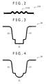
- the portion to be pressed 31 is configured to have such a curved shape, thereby sufficiently securing the line length required for the thickening. More specifically, a longer line length can be secured compared with the case where a microbead 310A formed by a continuous protruded and recessed region is formed on a portion to be pressed 310 in a flat plate shape as shown in a comparative example of FIG. 2 .
- the length (line length) from one end of the portion to be pressed 31 to the other end along the portion to be pressed 31 can be greatly increased, thereby increasing a thickened amount of the portion to be pressed 31 according to this embodiment compared with the comparative example in which the microbead 310A is formed.
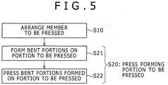
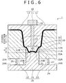
- the shape of the portion to be pressed 31 is not limited to the trapezoidal shape in the cross sectional view as described above, may be a shape bent in a rectangular shape in the cross sectional view as in FIG. 3 , or may be bent in an arc (arch) shape in the cross sectional view as shown in FIG. 4 .
- the first die 10 includes an upper press forming surface 10A in a wave shape for pressing one main surface of the portion to be pressed 31 as shown in FIG. 1 .
- the first die 10 includes a first die center portion 11 arranged at the center of the first die 10 and first die surrounding portions 12 formed separately from the first die center portion 11, and arranged on respective sides of the first die center portion 11 so as to sandwich side surfaces of the first die center portion 11.
- the upper press forming surface 10A is constructed by a first forming surface 11A provided at a bottom end of the first die center portion 11 and second forming surfaces 12A provided at respective bottom ends of the first die surrounding portions 12.
- the upper press forming surface 10A has a surface including a continuous protruded and recessed region by aligning the height of the first forming surface 11A and the height of the second forming surfaces 12A to each other as shown in FIG. 8 .
- the first die 10 includes the upper press forming surface 10A, and includes an upper forming die portion 74, which is a portion for applying the press forming to the portion to be pressed 31, and upper sandwiching die portions 75 and 76 for sandwiching and fixing the surrounding portions 32 and 33 as shown in FIG. 1 .
- the upper forming die portion 74 is formed integrally by the first die center portion 11 and parts of the first die surrounding portions 12.
- the upper sandwiching die portions 75 and 76 are formed as portions of the first die surrounding portions 12.
- the first die center portion 11 and the first die surrounding portions 12 are configured to be moved by the driving section 40 in the up/down direction independently of each other. In other words, only the first die surrounding portions 12 can be moved in the up/down direction while the position of the first die center portion 11 is fixed, and only the first die center portion 11 can be moved in the up/down direction while the positions of the first die surrounding portions 12 are fixed.
- a pressing portion 14 in a shape protruding downward toward the second die 20 is provided on the first forming surface 11A of the first die center portion 11.
- the pressing portion 14 is a center portion of the first forming surface 11A, and protrudes downward more than portions on both sides thereof.
- a second bent portion 31B bending in a protruded shape toward the first die 10 is formed on the portion to be pressed 31 during the press forming as shown in FIG. 7 , and the second bent portion 31B can be pressed by the pressing portion 14.
- the second die 20 includes a lower press forming surface 20A in a wave shape opposing the upper press forming surface 10A of the first die 10 as shown in FIG. 1 .
- the second die 20 includes a second die center portion 21, and second die surrounding portions 22 formed independently of the second die center portion 21.
- the second die center portion 21 includes a support portion 24 placed on a horizontal surface, and a forming portion 25 standing upward from an approximate center of the support portion 24 toward the first die 10.
- the lower press forming surface 20A is provided on a top of the forming portion 25.
- the lower press forming surface 20A is formed of a continuous protruded and recessed region as the upper press forming surface 10A, and has a length the same as the width of the protruded and recessed region 91A formed on the press-formed article 90 shown in FIG. 12 .
- protruded portions of the upper press forming surface 10A oppose recessed portions of the lower press forming surface 20A, and recessed portions of the upper press forming surface 10A oppose protruded portions of the lower press forming surface 20A. Therefore, a protruded and recessed region along the protruded and recessed surfaces of the upper and lower press forming surfaces 10A and 20A can be formed on the portion to be pressed 31 by using the upper press forming surface 10A and the lower press forming surface 20A to apply the press forming to the portion to be pressed 31 in the wave shape as shown in FIG. 9 .
- Two first bent portions 31A each bent in a protruded shape toward the second die 20 are formed on the portion to be pressed 31 so as to be separated from each other on the portion to be pressed 31 during the press forming as shown in FIG. 7 .
- the two first bent portions 31A can be held by groove-shaped holding portions 20B in a pair provided on the lower press forming surface 20A.
- the holding portions 20B are provided so as to be separated from each other, thereby positioning on respective sides of a recessed groove positioned at the center of the lower press forming surface 20A, and are positioned outside the pressing portion 14 of the first die 10.
- the pressing portion 14 is positioned between the two holding portions 20B.
- the second die surrounding portions 22 are arranged so as to oppose the first die surrounding portions 12 in the up/down direction, and sandwich the surrounding portions 32 and 33 in gaps with the first die surrounding portions 12 as illustrated in FIG. 1 .
- Bottom end surfaces 22A of the second die surrounding portions 22 are connected to one ends of elastic members 26 and 27 such as springs, and the second die surrounding portions 22 are connected to a top surface 24A of the support portion 24 via the elastic members 26 and 27.
- the second die surrounding portions 22 are positioned so as to form steps on a upper side with respect to the forming portion 25 of the second die center portion 21 in the state before the start of the pressing shown in FIG.
- a press space S for storing the portion to be pressed 31 is formed between the upper press forming surface 10A and the lower press forming surface 20A as a result. Then, the first die surrounding portions 12 move down, thereby downward pressing the second die surrounding portions 22, the elastic members 26 and 27 thus contract, and the second die surrounding portions 22 move down while sliding over side surfaces of the forming portion 25. As a result, the press space S gradually decreases, and the portion to be pressed 31 is pressed.
- the second die center portion 21 corresponds to a lower forming die portion for applying, together with the upper forming die portion 74, the press forming to the portion to be pressed 31, and the second die surrounding portions 22 correspond to lower sandwiching die portions for sandwiching and fixing, together with the upper sandwiching die portions 75 and 76, the surrounding portions 32 and 33.
- the lower forming die portion and the lower sandwiching die portions are constructed independently of each other according to this embodiment.
- the driving section 40 is used to move down the first die 10 so as to approach the second die 20. As a result, the press space S can be decreased, thereby applying the press forming to the portion to be pressed 31.
- the driving section 40 is arranged at a top portion of the first die 10, and includes a reciprocally movable hydraulic or electric piston.
- the first die center portion 11 and the first die surrounding portions 12 can be upward/downward moved independently of each other by using the piston to press these portions.
- FIGS 1 and 6 to 10 sequentially show a process of moving down the first die 10 toward the second die 20, thereby decreasing the press space S to apply the press forming to the portion to be pressed 31.
- a description is given of the hot pressing for applying the press forming to the member to be pressed 30 softened by heating according to this embodiment, but this manufacturing method is not limited to the hot pressing, and can be similarly used for cold working.
- the member to be pressed 30 in the flat plate shape formed of various metal materials such as hard steel is prepared, and the member to be pressed 30 is machined to form the portion to be pressed 31 bent in the trapezoidal shape. Then, the member to be pressed 30 is heated in an electric furnace, or is heated by supplying an electric current, thereby being brought into the softened state.
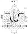
- Step S10 for arranging the member to be pressed 30 in the press forming apparatus 1 is carried out.
- the member to be pressed 30 softened by the heating is arranged between the first die 10 and the second die 20.
- the surrounding portions 32 and 33 are arranged between the first die surrounding portions 12 and the second die surrounding portions 22, and the portion to be pressed 31 is arranged in the press space S.
- Step S20 for applying the press forming to the member to be pressed 31 is carried out.
- the first die 10 is moved so as to approach the second die 20 to decrease the press space S, thereby applying the press forming to the portion to be pressed 31 so that the height H of the portion to be pressed 31 decreases.
- Step S20 a bending step S21 for forming the first bent portions 31A and the second bent portion 31B on the portion to be pressed 31 as shown in FIG. 7 , and a deformation step S22 for pressing the second bent portion 31B to deform while the first bent portion 31A are held by the holding portions 20B as shown in FIG. 8 are carried out in sequence.
- the first die surrounding portions 12 are moved downward toward the second die surrounding portions 22 by the driving section 40 while the position of the first die center portion 11 is fixed in the state of FIG. 1 .
- the surrounding portions 32 and 33 are sandwiched and fixed by the first die surrounding portions 12 and the second die surrounding portions 22 as shown in FIG. 6 .
- a flow of the material toward the surrounding portions 32 and 33 are prevented.
- the press space S is decreased by further moving downward the first die surrounding portions 12, thereby gradually decreasing the height H of the portion to be pressed 31. Then, when the height H of the portion to be pressed 31 becomes equal to or less than a predetermined value, the portion to be pressed 31 bends, and the pair of first bent portions 31A each bent in the protruded shape toward the second die 20 and the second bent portion 31B bent in the protruded shape from the position between the pair of the first bent portions 31A toward the first die 10 are formed on the portion to be pressed 31 as shown in FIG. 7 .
- the material between the holding portions 20B and the surrounding portions 32 and 33 flows toward the holding portions 20B, and further flows from the holding portions 20B toward the pressing portion 14 as the first die 10 approaches the second die 20 while the surrounding portions 32 and 33 are fixed.
- the first bent portions 31A swell out so as to fit into the recessed grooves of the holding portions 20B, and are thus fixed in position as shown in FIG. 7
- the second bent portion 31B swells out upward so as to oppose the pressing portion 14 of the first die 10.
- both the first die center portion 11 and the first die surrounding portions 12 are moved downward by the driving section 40, and the second bent portion 31B is pressed by the pressing portion 14 of the first die 10 while the first bent portions 31A are held by the holding portions 20B as shown in FIG. 8 in Step S22 for the deformation.
- the second bent portion 31B deforms so as to bend downward.
- the material flows in the portion to be pressed 31, but a flow of the material toward the outsides of the holding portions 20B (namely toward the surrounding portions 32 and 33) is suppressed by the first bent portions 31A being held by the holding portions 20B, and an excessive amount of the material is prevented from unevenly being distributed to the both sides of the portion to be pressed 31.
- the material is also prevented from entering the surrounding portions 32 and 33 by the ends of the surrounding portions 32 and 33 connected to the portion to be pressed 31 being sandwiched by the first die surrounding portions 12 and the second die surrounding portions 22.
- An excessive amount of the material is prevented from being unevenly distributed in the center portion of the portion to be pressed 31 by the second bent portion 31B being pressed by the pressing portion 14.
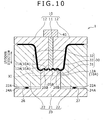
- the movements of the first die center portion 11 and the first die surrounding portions 12 are stopped when these portions are moved downward until the height H of the portion to be pressed 31 disappears as shown in FIGS. 9 and 10 , and the press forming is completed.
- a distance L1 between the pressing portion 14 and a portion of the second die 20 opposing the pressing portion 14 (bottom surface of the recessed groove on the lower press forming surface 20A) and a distance L2 between the bottom surface of the holding portion 20B and a portion of the first die 10 opposing the bottom surface of the holding portion 20B (the protruded portion on the upper press forming surface 10A) are the same when the pressing is completed as shown in an enlarged view in FIG. 11 .
- the portion to be pressed 31 is thickened as the height H decreases by applying the press forming to the portion to be pressed 31 in the height direction (namely, the up/down direction) while the material is prevented from flowing toward the surrounding portions 32 and 33.
- a plate thickness T1 of the portion to be pressed 31 is thickened more than a plate thickness T2 of the surrounding portions 32 and 33 (portions other than the portion to be pressed 31), resulting in manufacturing of a partially thickened press-formed article as shown in FIG. 11 .
- the plate thicknesses T1 and T2 are respectively the thinnest plate thicknesses (lowest plate thicknesses) of the portion to be pressed 31 and the surrounding portions 32 and 33.
- the protruded and recessed region 91A in the shape along the protruded and recessed surfaces of the upper and lower press forming surfaces 10A and 20A is formed simultaneously with the thickening on the portion to be pressed 31 after the forming.
- the first die 10 is moved upward by the driving section 40, and the press-formed article is taken out after the press forming is completed in this way.
- the press-formed article 90 is a component used as a frame member of an automobile such as a front pillar, a cross member, and a side sill, and is manufactured by the manufacturing method of a press-formed article according to this embodiment.
- the press-formed article 90 has the shape machined into the hat shape, and includes a top plate portion 91 thickened by the press forming applied to the portion to be pressed 31, vertical wall portions 92 and 93 connected to respective ends of the top plate portion 91, and flange portions 94 and 95 connected to ends (ends on opposite sides of the sides connecting to the top plate portion 91) of the vertical wall portions 92 and 93 as shown in FIG. 12 .
- the vertical wall portions 92 and 93 and the flange portions 94 and 95 are portions corresponding to the surrounding portions 32 and 33 (see FIG. 1 .), and are less in the plate thickness than the top plate portion 91. In other words, the press-formed article 90 is partially thickened at the top plate portion 91.
- the continuous protruded and recessed region 91A is formed so as to follow the protruded and recessed surfaces of the press forming surfaces 10A and 20A of the first die 10 and the second die 20 on the top plate portion 91 (thickened portion) as shown in FIG. 12 .
- This protruded and recessed region 91A is a portion in a wave shape formed so as to repeat in a sufficiently small width than a width W in the left/right direction in FIG. 12 of the top plate portion 91.
- the strength in the thickened portion 91 is increased by providing the protruded and recessed region 91A compared with a case where the region is in a flat surface shape.
- the press forming apparatus 1 is an apparatus for manufacturing the press-formed article 90 by applying the press forming to the portion to be pressed 31 in the bent shape (curved shape) formed on the member to be pressed 30 in the plate shape.
- the press forming apparatus 1 includes the first die 10 that has the upper press forming surface 10A, the second die 20 that has the lower press forming surface 20A opposing the upper press forming surface 10A, and forms the press space S for storing the portion to be pressed 31 in the gap with the first die 10, and the driving section 40 that relatively moves the first die 10 and the second die 20 so as to approach each other, thereby decreasing the press space S.
- the groove-shaped holding portions 20B are provided on the second die 20 so as to be separated from each other for holding the two first bent portions 31A on the portion to be pressed 31.
- the first die 10 includes the pressing portion 14 that is positioned between the two holding portions 20B, has the shape protruding toward the second die 20, and presses the second bent portion 31B on the portion to be pressed 31.
- the manufacturing method of a press-formed article is the method of manufacturing the press-formed article 90 by applying the press forming to the portion to be pressed 31 in the curved shape formed on the member to be pressed 30 in the plate shape.
- the manufacturing method includes Step S10 of arranging the member to be pressed 30 between the first die 10 and the second die 20, and Step S20 for relatively moving the first die 10 and the second die 20 so as to approach each other, thereby applying the press forming to the portion to be pressed 31 so that the height H of the portion to be pressed 31 decreases.
- Step S20 for applying the press forming while the pair of first bent portions 31A each bent in the protruded shape toward the second die 20 on the portion to be pressed 31 are held by the pair of holding portions 20B each in the groove shape provided so as to be separated from each other on the second die 20, the second bent portion 31B bent in the protruded shape from the position between the first bent portions 31A toward the first die 10 on the portion to be pressed 31 is pressed by the pressing portion 14 of the first die 10, thereby deforming the second bent portion 31B so as to thicken the portion to be pressed 31.
- the thickened portion can be formed by constructing the portion to be pressed 31 in the bent shape so as to secure the line length required for the thickening, and applying the press forming so as to decrease the height H of the portion to be pressed 31. Therefore, a longer line length required for the thickening can be secured compared with the case of the comparative example shown in FIG. 2 where the microbead 310A is formed on the portion to be pressed 310 in the flat plate shape, and the press-formed article 90 more in the thickened amount can be manufactured.
- the second bent portion 31B provided between the first bent portions 31A is pressed by the pressing portion 14 of the first die 10 while the first bent portions 31A are held by the holding portions 20B of the second die 20 during the press forming of the portion to be pressed 31.
- the material can be prevented from unevenly being distributed to the both sides or the center portion of the portion to be pressed 31.
- An intended thickened amount can be obtained, and a local thinning that may be a start point of a crack in the press-formed article 90 can be prevented by controlling the flow of the material during the press forming in this way.
- the press-formed article in a desired shape can appropriately be obtained.
- Step S20 for applying the press forming the press forming is applied to the portion to be pressed 31 so as to increase in the plate thickness more than the potions (surrounding portions 32 and 33) other than the portion to be pressed 31 in the member to be pressed 30.
- the press-formed article 90 increased in the strength can be manufactured by partially forming the thickened portion.
- Step S20 for applying the press forming the press forming is applied to the portion to be pressed 31 until the height H of the portion to be pressed 31 disappears after the forming, in other words, the ends of the surrounding portions 32 and 33 connected to the portion to be pressed 31 and the portion to be pressed 31 are approximately at the same positions in the up/down direction.
- the thickened amount on the portion to be pressed 31 can be increased, and the press-formed article 90 increased more in the strength can be manufactured.
- the member to be pressed 30 includes the surrounding portions 32 and 33 connected to the ends of the portion to be pressed 31.
- Step S20 for applying the press forming the portions of the surrounding portions 32 and 33 connected to the portion to be pressed 31 are sandwiched by the first die 10 (first die surrounding portions 12) and the second die 20 (second die surrounding portions 22).
- the flow of the material from the ends of the portion to be pressed 31 toward the center portion can be promoted during the press forming, thereby more effectively suppressing the uneven distribution of an excessive amount of the material to the ends of the portion to be pressed 31.
- Step S20 for applying the press forming the first bent portions 31A and the second bent portion 31B are formed on the portion to be pressed 31. More specifically, Step S20 for applying the press forming includes the bending step S21 for forming the first bent portions 31A and the second bent portion 31B on the portion to be pressed 31, and the deformation step S22 for pressing and deforming the second bent portion 31B while the first bent portions 31A are held by the holding portions 20B.
- the formation of the first and second bent portions 31A and 31B on the portion to be pressed 31 during the press forming in this way can eliminate the necessity of the formation of the first and second bent portions 31A and 31B in advance before the press forming, thereby increasing the efficiency of the manufacturing process.
- the first die 10 includes the first die center portion 11 including the pressing portion 14, and the first die surrounding portions 12 formed independently of the first die center portion 11, and configured to move independently of the first die center portion 11.
- Step S20 for applying the press forming after the first bent portions 31A and the second bent portion 31B are formed on the portion to be pressed 31 by moving the first die surrounding portions 12, the second bent portion 31B is pressed and deformed by the pressing portion 14. More specifically, in Step S21 for the bending, the first bent portions 31A and the second bent portion 31B are formed on the portion to be pressed 31 by moving downward the first die surrounding portions 12.
- the second bent portion 31B is pressed and deformed by the pressing portion 14 by downward moving the first die center portion 11 in Step S22 for the deformation.
- the first die center portion 11 can be started to move after the second bent portion 31B is formed on the portion to be pressed 31 during the press forming, thereby using the pressing portion 14 to surely press the second bent portion 31B.
- the distance L1 between the pressing portion 14 and the second die 20 and the distance L2 between the holding portions 20B and the first die 10 are the same when Step S20 for the press forming is completed.
- the thickness of the portion to be pressed 31 can be uniform.
- Step S20 for applying the press forming the protruded and recessed region 91A is provided on the portion to be pressed 31.
- the press-formed article 90 reinforced by the protruded and recessed region 91A and thus increased in the strength can be manufactured.
- the member to be pressed 30 may be formed by the hot pressing.
- the flow of the material in the portion to be pressed 31 can be controlled according to this embodiment as described above, and the intended thickened amount can be thus obtained even in the case of the hot pressing in which the material is likely to flow during the press forming.
- the protruded and recessed region 91A can be provided without changing the plate thickness of the portion to be pressed 31 before and after the pressing in Step S22 for the deformation according to the first embodiment.
- the strength of the press-formed article can be secured by providing the protruded and recessed region 91A even in this case.
- a height in the up/down direction (refer to FIG. 9 ) of a protruded and recessed portion of the protruded and recessed region 91A namely a distance between a top and a bottom, is more than that in the case where the portion to be pressed 31 is thickened.
- the portion to be pressed 31 only needs not to be decreased in the plate thickness by the press forming in this way, and the press forming may be applied for the thickening as in the first embodiment, or the press forming may be applied so as to maintain a constant plate thickness of the portion to be pressed 31.
- the press forming apparatus 2 is an apparatus for manufacturing a press-formed article by applying the press forming to a portion to be pressed 71 bent in an M shape in the cross sectional view formed on a member to be pressed 70 in a plate shape as shown in FIG. 13 .
- the line length of the portion to be pressed 71 is more than the length along the protruded and recessed region 91A on the press-formed article 90 shown in FIG. 12 as in the first embodiment.
- the press forming apparatus 2 includes an upper die 50, a lower die 60, and the driving section 40.
- a pressing portion 61 is provided on the lower die 60 as described later according to the second embodiment, and the lower die 60 corresponds to the first die 10 on which the pressing portion 14 shown in FIG. 1 is provided.
- the lower die 60 is referred to as "first die 60" hereinafter.
- Holding portions 50B are provided on the upper die 50, and the upper die 50 corresponds to the second die 20 on which the holding portions 20B shown in FIG. 1 are provided.
- the upper die 50 is referred to as “second die 50” hereinafter.
- the driving section 40 moves the second die 50 so as to approach the first die 60 or so as to depart from the first die 60 in the up/down direction. In other words, the second die 50 is moved upward/downward while the position of the first die 60 is fixed according to the second embodiment, which is different from the first embodiment.
- the second die 50 includes a second die center portion 51 in a block shape on which an upper press forming surface 50A in a wave shape is formed and second die surrounding portions 52 each in a block shape arranged so as to sandwich both side surfaces of the second die center portion 51.
- the driving section 40 is arranged on a top portion of the second die center portion 51, and the second die center portion 51 is configured to be upward/downward moved by the driving section 40.
- the upper press forming surface 50A is constructed by a continuous protruded and recessed region, and two recessed grooves constitute the holding portions 50B provided so as to be separated from each other, thereby existing on both sides of a center recessed groove. Two first bent portions 71A formed on the portion to be pressed 71 can be held by the holding portions 50B.
- the second die center portion 51 corresponds to the upper forming die portion and the second die surrounding portions 52 correspond to the upper sandwiching die portions according to this embodiment.
- the first die 60 includes a lower press forming surface 60A in a wave shape opposing the upper press forming surface 50A.
- the portion to be pressed 71 is stored in the press space S formed between the upper press forming surface 50A and the lower press forming surface 60A, and surrounding portions 72 and 73 are arranged between the second die surrounding portions 52 and the first die 60.
- the lower press forming surface 60A includes a pressing portion 61 in a shape protruding toward the second die 50 at its center, and can use the pressing portion 61 to press a second bent portion 71B formed on the portion to be pressed 71.
- the pressing portion 61 is a part of the first die 60 according to this embodiment, and the pressing portion 61 integrally moves with other die portions, which is different from the first embodiment.
- a portion on which the lower press forming surface 60A is formed at the center portion of the first die 60 corresponds to the lower forming die portion, and portions on both sides thereof correspond to the lower sandwiching die portions according to this embodiment.
- the lower forming die portion and the lower sandwiching die portions are integrally formed as the single first die 60 according to this embodiment, which is different from the first embodiment.
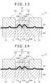
- the member to be pressed 70 on which the first bent portions 71A and the second bent portion 71B are formed in advance by bending on the portion to be pressed 71, is prepared, is brought into a softened state by heating, and then is arranged between the second die 50 and the first die 60 as shown in FIG. 13 in Step S10 (see FIG. 5 .).
- the portion to be pressed 71 is positioned in the press space S, and the surrounding portions 72 and 73 are sandwiched and fixed by the second die surrounding portion 52 and the first die 60.
- the press space S is decreased by using the driving section 40 to move down the second die center portion 51 toward the first die 60 in Step S20 (see FIG. 5 .).
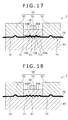
- the height H of the portion to be pressed 71 gradually decreases, thereby increasing the thickness of the portion to be pressed 71 in the state where the surrounding portions 72 and 73 are sandwiched as sequentially shown in FIGS. 14 to 18 .
- the member to be pressed 70 on which the first bent portions 71A and the second bent portion 71B are formed in advance on the portion to be pressed 71 is prepared, and the press-formed article is manufactured by applying the press forming to the member to be pressed 70 according to the second embodiment in this way.
- the first bent portions 71A can surely be formed at the positions opposing the holding portions 50B of the second die 50, and the second bent portion 71B can surely be formed at the position opposing the pressing portion 61 of the first die 60 by forming the first and second bent portions 71A and 71B on the portion to be pressed 71 in advance before the press forming in this way.
- the first bent portions 71A can more surely be held by the holding portions 50B, and the second bent portion 71B can more surely be pressed by the pressing portion 61 during the press forming.
- the pressing portion 61 may be in contact with the second bent portion 71B in the state before the start of the pressing as shown in FIG. 13 , but the configuration is not limited to this case, a gap may be formed between the pressing portion 61 and the second bent portion 71B in the state before the start of the press, and the pressing portion 61 may be brought in contact with the second bent portion 71B by moving down the second die center portion 51 during the pressing.
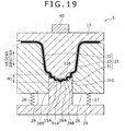
- a first die 15 includes an upper press forming surface 15A in a wave shape, and the upper press forming surface 15A has a protruded shape at a center swelling out toward a second die center portion 28 (second die) in the press forming apparatus 3 as shown in FIG. 19 .
- a pressing portion 15B is provided at a top of the upper press forming surface 15A as in the first embodiment.
- the second die center portion 28 includes a lower press forming surface 28A in a wave shape opposing the upper press forming surface 15A, and the lower press forming surface 28A has a recessed shape so as to depart from the first die 15. Continuous protruded and recessed regions are formed on the upper and lower press forming surfaces 15A and 28A as in the first embodiment.
- a pair of holding portions 28B is provided so as to be separated from each other on the lower press forming surface 28A as in the first embodiment.
- the member to be pressed 30 is arranged so that the portion to be pressed 31 is positioned between the upper and lower press forming surfaces 15A and 28A, and the surrounding portions 32 and 33 are positioned between the first die 15 and the second die surrounding portions 29, and the press forming is applied to the portion to be pressed 31 by moving down the first die 15 in the press forming apparatus 3.
- the press forming is applied to the portion to be pressed 31 so as to have a bent shape 31G in a protruded shape toward the second die center portion 28 along the shapes of the upper and lower press forming surfaces 15A and 28A.
- the bent shape 31G is a shape curved so as to protrude toward the second die center portion 28 as shown in FIG. 19 .
- the protruded and recessed region 91A is simultaneously formed on the bent shape 31G.
- a height HI of the portion to be pressed 31 after the forming is less than the height H ( FIG. 1 ) of the portion to be pressed 31 in a trapezoidal shape before the forming.
- a width of the bent shape 31G in the left/right direction of FIG. 19 is more than a width of the protruded and recessed region 91A.
- the press-formed article bent in the thickened portion can be manufactured by using the dies on which the press forming surfaces 15A and 28A in the shapes described above are formed according to this embodiment.
- the press forming may be applied to the portion to be pressed 31 so as to include a bent shape protruded toward the first die 15 conversely in this embodiment.
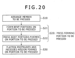
- Step S10 of arranging the member to be pressed 30 and Step S20 for applying the press forming to the portion to be pressed 31 are sequentially carried out as in the first embodiment
- Step S30 of flattening the protruded and recessed region of the portion to be pressed 31 is further carried out according to the fourth embodiment as shown in FIG. 20 .
- the protruded and recessed region 31D can be flattened by arranging the portion to be pressed 31 on which the continuous protruded and recessed region 31D is formed between dies 83 and 84 including press forming surfaces 83A and 84A each in a flat surface shape, and using the press forming surfaces 83A and 84A to press the portion to be pressed 31 in the thickness direction as shown in FIG. 21 .
- a press-formed article including a thickened portion 34 on which the protruded and recessed region disappears, and a flat surface 34A is formed can be manufactured as shown in FIG. 22 .
- the plate material can be prevented from being buckled by flattening the protruded and recessed region 31D after once forming the protruded and recessed region 31D on the portion to be pressed 31 in this way, which is different from the case where the portion to be pressed 31 is directly formed into the flat shape.
- a step of using dies and the like to press and flatten the protruded and recessed region 91A in the thickness direction after the protruded and recessed region 91A is formed on the bent shape 31G may be carried out also according to the third embodiment as in the fourth embodiment.
- the protruded and recessed shapes on the upper press forming surface 10A of the first die 10 and the lower press forming surface 20A of the second die 20 may be left-right asymmetric in the cross sectional view as shown in FIG. 23 .
- the width of the recessed grooves may not be the same over the entire surface.
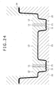
- a plurality (two) of portions to be pressed 31 may be formed on the member to be pressed 30, and a press-formed article on which a plurality of thickened portions are formed may be manufactured by applying the press forming to the portions to be pressed 31 as shown in FIG. 24 .
- the number of provided portions to be pressed 31 may be equal to or more than three.
- the portion to be pressed is not necessarily be uniformly thickened as long as the desired strength is provided for the press-formed article according to the first embodiment. The same holds true for the other embodiments.
- the configuration according to the first embodiment is not limited to the case where the second bent portion 31B is formed at the center of the portion to be pressed 31, and the second bent portion 31B may be formed at a position closer to one of the ends of the portion to be pressed 31 rather than at the center thereof.
- the configuration is not limited to the case where only the pair of first bent portions 31A and the one second bent portion 31B positioned therebetween are formed on the portion to be pressed 31, and a plurality of pairs of first bent portions 31A and the second bent portions 31B respectively positioned therebetween may be formed.
- the configuration according to the first embodiment is not limited to the case where only the first die 10 moves, and the second die 20 may move upward, or both the first die 10 and the second die 20 may move.
- the first die center portion 11 and the first die surrounding portions 12 may be integrated with each other.
Applications Claiming Priority (1)
| Application Number | Priority Date | Filing Date | Title |
|---|---|---|---|
| JP2016015907A JP6659380B2 (ja) | 2016-01-29 | 2016-01-29 | プレス成形品の製造方法及びプレス成形装置 |
Publications (2)
| Publication Number | Publication Date |
|---|---|
| EP3199256A1 EP3199256A1 (en) | 2017-08-02 |
| EP3199256B1 true EP3199256B1 (en) | 2019-03-13 |
Family
ID=57868010
Family Applications (1)
| Application Number | Title | Priority Date | Filing Date |
|---|---|---|---|
| EP17000007.9A Active EP3199256B1 (en) | 2016-01-29 | 2017-01-03 | Manufacturing method of press-formed article and press forming apparatus |
Country Status (4)
| Country | Link |
|---|---|
| US (1) | US10300519B2 (zh) |
| EP (1) | EP3199256B1 (zh) |
| JP (1) | JP6659380B2 (zh) |
| CN (1) | CN107020335B (zh) |
Families Citing this family (13)
| Publication number | Priority date | Publication date | Assignee | Title |
|---|---|---|---|---|
| JP6659733B2 (ja) * | 2016-07-13 | 2020-03-04 | 日本製鉄株式会社 | ホットスタンプ成形品の製造方法 |
| JP6721544B2 (ja) | 2017-06-28 | 2020-07-15 | 株式会社神戸製鋼所 | プレス成形品の製造方法 |
| CN109256884A (zh) | 2017-10-13 | 2019-01-22 | 朱卫 | 一种用钛金属生产的马达外壳 |
| JP7017944B2 (ja) * | 2018-02-09 | 2022-02-09 | 株式会社三井ハイテック | 金属成形体の製造方法 |
| WO2019187863A1 (ja) * | 2018-03-28 | 2019-10-03 | Jfeスチール株式会社 | プレス成形品の設計方法、プレス成形金型、プレス成形品およびプレス成形品の製造方法 |
| CN108817230B (zh) * | 2018-07-19 | 2019-12-03 | 安徽江淮汽车集团股份有限公司 | 一种模具结构 |
| JP6677289B1 (ja) * | 2018-12-12 | 2020-04-08 | Jfeスチール株式会社 | プレス成形方法 |
| JP7110144B2 (ja) * | 2019-03-15 | 2022-08-01 | 本田技研工業株式会社 | 車体フレームの製造方法 |
| JP2020146747A (ja) | 2019-03-15 | 2020-09-17 | 本田技研工業株式会社 | 車体フレームの製造方法、及び車体フレーム |
| CN112676416B (zh) * | 2019-10-17 | 2023-05-05 | 本田技研工业株式会社 | 车身骨架构件的制造方法 |
| CN110993128A (zh) * | 2019-12-02 | 2020-04-10 | 吉林农业大学 | 一种压水堆燃料组件用的格架 |
| CN111940605B (zh) * | 2020-08-04 | 2022-09-23 | 惠州融汇科技有限公司 | 新能源汽车电池箱体顶盖成型结构 |
| CN114101474A (zh) * | 2020-08-31 | 2022-03-01 | 宝山钢铁股份有限公司 | 一种模组背板凸包二道次成形加工方法 |
Family Cites Families (19)
| Publication number | Priority date | Publication date | Assignee | Title |
|---|---|---|---|---|
| USRE16115E (en) * | 1925-07-14 | Poration | ||
| US1771028A (en) * | 1928-12-31 | 1930-07-22 | Kewanee Boiler Corp | Method of corrugating metal boiler sheets |
| SE463082B (sv) * | 1986-10-24 | 1990-10-08 | Nordisk Kartro Ab | Anordning foer profilering av en stegvis frammatad materialbana |
| FR2660220B1 (fr) * | 1990-04-03 | 1995-02-24 | Lorraine Laminage | Procede et dispositif de formage d'une partie en relief sur un flan de tole et produit obtenu selon ce procede. |
| JPH05154572A (ja) * | 1991-12-03 | 1993-06-22 | Matsushita Electric Ind Co Ltd | 成形方法とその成形金型 |
| JP3950023B2 (ja) * | 2002-08-21 | 2007-07-25 | 中央精機株式会社 | 自動車用ホイールディスクの製造方法 |
| JP4418168B2 (ja) * | 2003-05-14 | 2010-02-17 | 本田技研工業株式会社 | 楕円形環体の製造方法 |
| JP2009072801A (ja) * | 2007-09-19 | 2009-04-09 | Topre Corp | ホットプレス部品の部分増厚方法及び部分増厚装置 |
| JP2011005552A (ja) * | 2008-09-01 | 2011-01-13 | Mazda Motor Corp | 金属製閉断面部材の製造方法 |
| JP5515279B2 (ja) * | 2008-11-20 | 2014-06-11 | 日産自動車株式会社 | プレス成形品、プレス成形品の製造方法および製造装置 |
| JP5470812B2 (ja) * | 2008-11-20 | 2014-04-16 | 日産自動車株式会社 | プレス成形品の製造方法および製造装置、並びにプレス成形品 |
| JP5416498B2 (ja) * | 2009-07-23 | 2014-02-12 | 本田技研工業株式会社 | テーラードブランク板の成形方法及びその装置 |
| JP5585103B2 (ja) * | 2010-02-04 | 2014-09-10 | トヨタ自動車株式会社 | 骨格部材および骨格部材の製造方法 |
| CN103547388B (zh) * | 2011-05-20 | 2015-10-07 | 新日铁住金株式会社 | 冲压成型方法以及车身部件 |
| WO2014208244A1 (ja) * | 2013-06-25 | 2014-12-31 | 日産自動車株式会社 | 薄板状基材の成形装置および成形方法 |
| JP6073194B2 (ja) | 2013-07-03 | 2017-02-01 | 昭和電工株式会社 | 磁気記録媒体、磁気記憶装置 |
| JP6237313B2 (ja) * | 2014-02-17 | 2017-11-29 | トヨタ自動車株式会社 | プレス部品の増厚加工方法及び車両用プレス部品 |
| JP6179665B2 (ja) * | 2014-03-28 | 2017-08-16 | 新日鐵住金株式会社 | 複数の増肉部分を有する板状成形体の製造方法及び複数の増肉部を有する板状成形体 |
| CN204770231U (zh) * | 2015-07-18 | 2015-11-18 | 宁波永诚五金机械有限公司 | 一种膨胀套筒的生产模具 |
-
2016
- 2016-01-29 JP JP2016015907A patent/JP6659380B2/ja active Active
- 2016-12-01 US US15/366,989 patent/US10300519B2/en active Active
- 2016-12-29 CN CN201611248434.9A patent/CN107020335B/zh active Active
-
2017
- 2017-01-03 EP EP17000007.9A patent/EP3199256B1/en active Active
Non-Patent Citations (1)
| Title |
|---|
| None * |
Also Published As
| Publication number | Publication date |
|---|---|
| JP2017131960A (ja) | 2017-08-03 |
| CN107020335A (zh) | 2017-08-08 |
| JP6659380B2 (ja) | 2020-03-04 |
| CN107020335B (zh) | 2019-08-20 |
| EP3199256A1 (en) | 2017-08-02 |
| US20170216901A1 (en) | 2017-08-03 |
| US10300519B2 (en) | 2019-05-28 |
Similar Documents
| Publication | Publication Date | Title |
|---|---|---|
| EP3199256B1 (en) | Manufacturing method of press-formed article and press forming apparatus | |
| US10022766B2 (en) | Press forming method and method of manufacturing press-formed part | |
| US8776570B2 (en) | Workpiece bending method and apparatus | |
| US10220427B2 (en) | Press-molding apparatus, press-molding method, and press-molded product | |
| RU2674059C2 (ru) | Способ изготовления, устройство для изготовления и производственная линия для изготовления штампованных деталей | |
| JP6028885B1 (ja) | プレス成形方法及びプレス成形装置 | |
| JP5835768B2 (ja) | フレーム部品の製造方法 | |
| KR101579028B1 (ko) | 폐단면 구조 부품의 제조 방법 및 장치 | |
| US20190105697A1 (en) | Press-molded product, press-molded product producing method, and press-molded product producing apparatus | |
| CA2920874C (en) | Method and press-forming apparatus for manufacturing structural member for automotive body | |
| JP4198445B2 (ja) | 車両用荷重受け物品の製造方法並びにその製造装置 | |
| TW201819063A (zh) | 壓製成形品的製造方法及製造裝置 | |
| CN110769948B (zh) | 加压成形品的制造方法 | |
| US20180361461A1 (en) | Manufacturing method of press-molded article and press molding apparatus | |
| JP2013103226A (ja) | 板金の曲げ癖矯正装置 | |
| WO2019049322A1 (ja) | ホットスタンプ成形品、その製造方法および製造装置 | |
| JP2008189311A (ja) | 車両用荷重受け物品 | |
| US20220055085A1 (en) | Press forming method | |
| JP2010149179A (ja) | プレス成形品の製造方法、プレス成形品の製造装置、およびプレス成形品 | |
| JP6550322B2 (ja) | プレス成形品の製造方法及びプレス成形装置 | |
| JP3931736B2 (ja) | プレス成形型 | |
| JP2020163397A (ja) | プレス成形方法及び金属板 | |
| JP2022139485A (ja) | プレス成形品の製造方法及び製造設備 | |
| JP2022116608A (ja) | プレス成形方法およびプレス成形金型 |
Legal Events
| Date | Code | Title | Description |
|---|---|---|---|
| PUAI | Public reference made under article 153(3) epc to a published international application that has entered the european phase |
Free format text: ORIGINAL CODE: 0009012 |
|
| STAA | Information on the status of an ep patent application or granted ep patent |
Free format text: STATUS: THE APPLICATION HAS BEEN PUBLISHED |
|
| AK | Designated contracting states |
Kind code of ref document: A1 Designated state(s): AL AT BE BG CH CY CZ DE DK EE ES FI FR GB GR HR HU IE IS IT LI LT LU LV MC MK MT NL NO PL PT RO RS SE SI SK SM TR |
|
| AX | Request for extension of the european patent |
Extension state: BA ME |
|
| STAA | Information on the status of an ep patent application or granted ep patent |
Free format text: STATUS: REQUEST FOR EXAMINATION WAS MADE |
|
| 17P | Request for examination filed |
Effective date: 20171116 |
|
| RBV | Designated contracting states (corrected) |
Designated state(s): AL AT BE BG CH CY CZ DE DK EE ES FI FR GB GR HR HU IE IS IT LI LT LU LV MC MK MT NL NO PL PT RO RS SE SI SK SM TR |
|
| RIC1 | Information provided on ipc code assigned before grant |
Ipc: B21D 22/06 20060101ALI20180517BHEP Ipc: B21D 22/22 20060101ALN20180517BHEP Ipc: B21D 13/02 20060101AFI20180517BHEP |
|
| GRAP | Despatch of communication of intention to grant a patent |
Free format text: ORIGINAL CODE: EPIDOSNIGR1 |
|
| STAA | Information on the status of an ep patent application or granted ep patent |
Free format text: STATUS: GRANT OF PATENT IS INTENDED |
|
| INTG | Intention to grant announced |
Effective date: 20180918 |
|
| GRAS | Grant fee paid |
Free format text: ORIGINAL CODE: EPIDOSNIGR3 |
|
| GRAA | (expected) grant |
Free format text: ORIGINAL CODE: 0009210 |
|
| STAA | Information on the status of an ep patent application or granted ep patent |
Free format text: STATUS: THE PATENT HAS BEEN GRANTED |
|
| AK | Designated contracting states |
Kind code of ref document: B1 Designated state(s): AL AT BE BG CH CY CZ DE DK EE ES FI FR GB GR HR HU IE IS IT LI LT LU LV MC MK MT NL NO PL PT RO RS SE SI SK SM TR |
|
| REG | Reference to a national code |
Ref country code: GB Ref legal event code: FG4D |
|
| REG | Reference to a national code |
Ref country code: CH Ref legal event code: EP Ref country code: AT Ref legal event code: REF Ref document number: 1107003 Country of ref document: AT Kind code of ref document: T Effective date: 20190315 |
|
| REG | Reference to a national code |
Ref country code: DE Ref legal event code: R096 Ref document number: 602017002557 Country of ref document: DE |
|
| REG | Reference to a national code |
Ref country code: IE Ref legal event code: FG4D |
|
| REG | Reference to a national code |
Ref country code: NL Ref legal event code: MP Effective date: 20190313 |
|
| REG | Reference to a national code |
Ref country code: LT Ref legal event code: MG4D |
|
| PG25 | Lapsed in a contracting state [announced via postgrant information from national office to epo] |
Ref country code: LT Free format text: LAPSE BECAUSE OF FAILURE TO SUBMIT A TRANSLATION OF THE DESCRIPTION OR TO PAY THE FEE WITHIN THE PRESCRIBED TIME-LIMIT Effective date: 20190313 Ref country code: FI Free format text: LAPSE BECAUSE OF FAILURE TO SUBMIT A TRANSLATION OF THE DESCRIPTION OR TO PAY THE FEE WITHIN THE PRESCRIBED TIME-LIMIT Effective date: 20190313 Ref country code: NO Free format text: LAPSE BECAUSE OF FAILURE TO SUBMIT A TRANSLATION OF THE DESCRIPTION OR TO PAY THE FEE WITHIN THE PRESCRIBED TIME-LIMIT Effective date: 20190613 Ref country code: SE Free format text: LAPSE BECAUSE OF FAILURE TO SUBMIT A TRANSLATION OF THE DESCRIPTION OR TO PAY THE FEE WITHIN THE PRESCRIBED TIME-LIMIT Effective date: 20190313 |
|
| PG25 | Lapsed in a contracting state [announced via postgrant information from national office to epo] |
Ref country code: NL Free format text: LAPSE BECAUSE OF FAILURE TO SUBMIT A TRANSLATION OF THE DESCRIPTION OR TO PAY THE FEE WITHIN THE PRESCRIBED TIME-LIMIT Effective date: 20190313 Ref country code: GR Free format text: LAPSE BECAUSE OF FAILURE TO SUBMIT A TRANSLATION OF THE DESCRIPTION OR TO PAY THE FEE WITHIN THE PRESCRIBED TIME-LIMIT Effective date: 20190614 Ref country code: HR Free format text: LAPSE BECAUSE OF FAILURE TO SUBMIT A TRANSLATION OF THE DESCRIPTION OR TO PAY THE FEE WITHIN THE PRESCRIBED TIME-LIMIT Effective date: 20190313 Ref country code: LV Free format text: LAPSE BECAUSE OF FAILURE TO SUBMIT A TRANSLATION OF THE DESCRIPTION OR TO PAY THE FEE WITHIN THE PRESCRIBED TIME-LIMIT Effective date: 20190313 Ref country code: BG Free format text: LAPSE BECAUSE OF FAILURE TO SUBMIT A TRANSLATION OF THE DESCRIPTION OR TO PAY THE FEE WITHIN THE PRESCRIBED TIME-LIMIT Effective date: 20190613 Ref country code: RS Free format text: LAPSE BECAUSE OF FAILURE TO SUBMIT A TRANSLATION OF THE DESCRIPTION OR TO PAY THE FEE WITHIN THE PRESCRIBED TIME-LIMIT Effective date: 20190313 |
|
| PG25 | Lapsed in a contracting state [announced via postgrant information from national office to epo] |
Ref country code: ES Free format text: LAPSE BECAUSE OF FAILURE TO SUBMIT A TRANSLATION OF THE DESCRIPTION OR TO PAY THE FEE WITHIN THE PRESCRIBED TIME-LIMIT Effective date: 20190313 Ref country code: AL Free format text: LAPSE BECAUSE OF FAILURE TO SUBMIT A TRANSLATION OF THE DESCRIPTION OR TO PAY THE FEE WITHIN THE PRESCRIBED TIME-LIMIT Effective date: 20190313 Ref country code: PT Free format text: LAPSE BECAUSE OF FAILURE TO SUBMIT A TRANSLATION OF THE DESCRIPTION OR TO PAY THE FEE WITHIN THE PRESCRIBED TIME-LIMIT Effective date: 20190713 Ref country code: CZ Free format text: LAPSE BECAUSE OF FAILURE TO SUBMIT A TRANSLATION OF THE DESCRIPTION OR TO PAY THE FEE WITHIN THE PRESCRIBED TIME-LIMIT Effective date: 20190313 Ref country code: IT Free format text: LAPSE BECAUSE OF FAILURE TO SUBMIT A TRANSLATION OF THE DESCRIPTION OR TO PAY THE FEE WITHIN THE PRESCRIBED TIME-LIMIT Effective date: 20190313 Ref country code: EE Free format text: LAPSE BECAUSE OF FAILURE TO SUBMIT A TRANSLATION OF THE DESCRIPTION OR TO PAY THE FEE WITHIN THE PRESCRIBED TIME-LIMIT Effective date: 20190313 Ref country code: SK Free format text: LAPSE BECAUSE OF FAILURE TO SUBMIT A TRANSLATION OF THE DESCRIPTION OR TO PAY THE FEE WITHIN THE PRESCRIBED TIME-LIMIT Effective date: 20190313 Ref country code: RO Free format text: LAPSE BECAUSE OF FAILURE TO SUBMIT A TRANSLATION OF THE DESCRIPTION OR TO PAY THE FEE WITHIN THE PRESCRIBED TIME-LIMIT Effective date: 20190313 |
|
| PG25 | Lapsed in a contracting state [announced via postgrant information from national office to epo] |
Ref country code: PL Free format text: LAPSE BECAUSE OF FAILURE TO SUBMIT A TRANSLATION OF THE DESCRIPTION OR TO PAY THE FEE WITHIN THE PRESCRIBED TIME-LIMIT Effective date: 20190313 Ref country code: SM Free format text: LAPSE BECAUSE OF FAILURE TO SUBMIT A TRANSLATION OF THE DESCRIPTION OR TO PAY THE FEE WITHIN THE PRESCRIBED TIME-LIMIT Effective date: 20190313 |
|
| REG | Reference to a national code |
Ref country code: DE Ref legal event code: R097 Ref document number: 602017002557 Country of ref document: DE |
|
| PG25 | Lapsed in a contracting state [announced via postgrant information from national office to epo] |
Ref country code: IS Free format text: LAPSE BECAUSE OF FAILURE TO SUBMIT A TRANSLATION OF THE DESCRIPTION OR TO PAY THE FEE WITHIN THE PRESCRIBED TIME-LIMIT Effective date: 20190713 |
|
| PLBE | No opposition filed within time limit |
Free format text: ORIGINAL CODE: 0009261 |
|
| STAA | Information on the status of an ep patent application or granted ep patent |
Free format text: STATUS: NO OPPOSITION FILED WITHIN TIME LIMIT |
|
| PG25 | Lapsed in a contracting state [announced via postgrant information from national office to epo] |
Ref country code: DK Free format text: LAPSE BECAUSE OF FAILURE TO SUBMIT A TRANSLATION OF THE DESCRIPTION OR TO PAY THE FEE WITHIN THE PRESCRIBED TIME-LIMIT Effective date: 20190313 |
|
| 26N | No opposition filed |
Effective date: 20191216 |
|
| PG25 | Lapsed in a contracting state [announced via postgrant information from national office to epo] |
Ref country code: SI Free format text: LAPSE BECAUSE OF FAILURE TO SUBMIT A TRANSLATION OF THE DESCRIPTION OR TO PAY THE FEE WITHIN THE PRESCRIBED TIME-LIMIT Effective date: 20190313 |
|
| PG25 | Lapsed in a contracting state [announced via postgrant information from national office to epo] |
Ref country code: TR Free format text: LAPSE BECAUSE OF FAILURE TO SUBMIT A TRANSLATION OF THE DESCRIPTION OR TO PAY THE FEE WITHIN THE PRESCRIBED TIME-LIMIT Effective date: 20190313 |
|
| PG25 | Lapsed in a contracting state [announced via postgrant information from national office to epo] |
Ref country code: MC Free format text: LAPSE BECAUSE OF FAILURE TO SUBMIT A TRANSLATION OF THE DESCRIPTION OR TO PAY THE FEE WITHIN THE PRESCRIBED TIME-LIMIT Effective date: 20190313 |
|
| REG | Reference to a national code |
Ref country code: CH Ref legal event code: PL |
|
| REG | Reference to a national code |
Ref country code: BE Ref legal event code: MM Effective date: 20200131 |
|
| PG25 | Lapsed in a contracting state [announced via postgrant information from national office to epo] |
Ref country code: LU Free format text: LAPSE BECAUSE OF NON-PAYMENT OF DUE FEES Effective date: 20200103 |
|
| PG25 | Lapsed in a contracting state [announced via postgrant information from national office to epo] |
Ref country code: LI Free format text: LAPSE BECAUSE OF NON-PAYMENT OF DUE FEES Effective date: 20200131 Ref country code: CH Free format text: LAPSE BECAUSE OF NON-PAYMENT OF DUE FEES Effective date: 20200131 Ref country code: BE Free format text: LAPSE BECAUSE OF NON-PAYMENT OF DUE FEES Effective date: 20200131 |
|
| PG25 | Lapsed in a contracting state [announced via postgrant information from national office to epo] |
Ref country code: IE Free format text: LAPSE BECAUSE OF NON-PAYMENT OF DUE FEES Effective date: 20200103 |
|
| REG | Reference to a national code |
Ref country code: AT Ref legal event code: UEP Ref document number: 1107003 Country of ref document: AT Kind code of ref document: T Effective date: 20190313 |
|
| PG25 | Lapsed in a contracting state [announced via postgrant information from national office to epo] |
Ref country code: MT Free format text: LAPSE BECAUSE OF FAILURE TO SUBMIT A TRANSLATION OF THE DESCRIPTION OR TO PAY THE FEE WITHIN THE PRESCRIBED TIME-LIMIT Effective date: 20190313 Ref country code: CY Free format text: LAPSE BECAUSE OF FAILURE TO SUBMIT A TRANSLATION OF THE DESCRIPTION OR TO PAY THE FEE WITHIN THE PRESCRIBED TIME-LIMIT Effective date: 20190313 |
|
| PG25 | Lapsed in a contracting state [announced via postgrant information from national office to epo] |
Ref country code: MK Free format text: LAPSE BECAUSE OF FAILURE TO SUBMIT A TRANSLATION OF THE DESCRIPTION OR TO PAY THE FEE WITHIN THE PRESCRIBED TIME-LIMIT Effective date: 20190313 |
|
| PGFP | Annual fee paid to national office [announced via postgrant information from national office to epo] |
Ref country code: AT Payment date: 20221228 Year of fee payment: 7 |
|
| PGFP | Annual fee paid to national office [announced via postgrant information from national office to epo] |
Ref country code: DE Payment date: 20221130 Year of fee payment: 7 |
|
| P01 | Opt-out of the competence of the unified patent court (upc) registered |
Effective date: 20230523 |
|
| PGFP | Annual fee paid to national office [announced via postgrant information from national office to epo] |
Ref country code: GB Payment date: 20231130 Year of fee payment: 8 |
|
| PGFP | Annual fee paid to national office [announced via postgrant information from national office to epo] |
Ref country code: FR Payment date: 20231212 Year of fee payment: 8 |
|
| PGFP | Annual fee paid to national office [announced via postgrant information from national office to epo] |
Ref country code: AT Payment date: 20231227 Year of fee payment: 8 |