EP3199256A1 - Manufacturing method of press-formed article, press-formed article, and press forming apparatus - Google Patents
Manufacturing method of press-formed article, press-formed article, and press forming apparatus Download PDFInfo
- Publication number
- EP3199256A1 EP3199256A1 EP17000007.9A EP17000007A EP3199256A1 EP 3199256 A1 EP3199256 A1 EP 3199256A1 EP 17000007 A EP17000007 A EP 17000007A EP 3199256 A1 EP3199256 A1 EP 3199256A1
- Authority
- EP
- European Patent Office
- Prior art keywords
- die
- pressed
- press
- press forming
- bent
- Prior art date
- Legal status (The legal status is an assumption and is not a legal conclusion. Google has not performed a legal analysis and makes no representation as to the accuracy of the status listed.)
- Granted
Links
- 238000004519 manufacturing process Methods 0.000 title claims abstract description 72
- 238000003825 pressing Methods 0.000 claims abstract description 67
- 230000007423 decrease Effects 0.000 claims abstract description 15
- 238000013459 approach Methods 0.000 claims abstract description 12
- 230000003247 decreasing effect Effects 0.000 claims description 11
- 238000007731 hot pressing Methods 0.000 claims description 7
- 239000000463 material Substances 0.000 description 27
- 239000011325 microbead Substances 0.000 description 10
- 238000005452 bending Methods 0.000 description 8
- 230000008719 thickening Effects 0.000 description 7
- 238000000034 method Methods 0.000 description 6
- 230000015572 biosynthetic process Effects 0.000 description 4
- 229910052751 metal Inorganic materials 0.000 description 4
- 239000002184 metal Substances 0.000 description 4
- 229910000831 Steel Inorganic materials 0.000 description 3
- 230000000052 comparative effect Effects 0.000 description 3
- 230000000694 effects Effects 0.000 description 3
- 238000010438 heat treatment Methods 0.000 description 3
- 239000010959 steel Substances 0.000 description 3
- 238000009826 distribution Methods 0.000 description 2
- 238000005516 engineering process Methods 0.000 description 2
- 239000007769 metal material Substances 0.000 description 2
- RYGMFSIKBFXOCR-UHFFFAOYSA-N Copper Chemical compound [Cu] RYGMFSIKBFXOCR-UHFFFAOYSA-N 0.000 description 1
- RTAQQCXQSZGOHL-UHFFFAOYSA-N Titanium Chemical compound [Ti] RTAQQCXQSZGOHL-UHFFFAOYSA-N 0.000 description 1
- 229910052782 aluminium Inorganic materials 0.000 description 1
- XAGFODPZIPBFFR-UHFFFAOYSA-N aluminium Chemical compound [Al] XAGFODPZIPBFFR-UHFFFAOYSA-N 0.000 description 1
- 229910052802 copper Inorganic materials 0.000 description 1
- 239000010949 copper Substances 0.000 description 1
- 230000005484 gravity Effects 0.000 description 1
- 238000003754 machining Methods 0.000 description 1
- 238000005482 strain hardening Methods 0.000 description 1
- 230000008961 swelling Effects 0.000 description 1
- 239000010936 titanium Substances 0.000 description 1
- 229910052719 titanium Inorganic materials 0.000 description 1
Images


Classifications
-
- B—PERFORMING OPERATIONS; TRANSPORTING
- B21—MECHANICAL METAL-WORKING WITHOUT ESSENTIALLY REMOVING MATERIAL; PUNCHING METAL
- B21D—WORKING OR PROCESSING OF SHEET METAL OR METAL TUBES, RODS OR PROFILES WITHOUT ESSENTIALLY REMOVING MATERIAL; PUNCHING METAL
- B21D53/00—Making other particular articles
- B21D53/88—Making other particular articles other parts for vehicles, e.g. cowlings, mudguards
-
- B—PERFORMING OPERATIONS; TRANSPORTING
- B21—MECHANICAL METAL-WORKING WITHOUT ESSENTIALLY REMOVING MATERIAL; PUNCHING METAL
- B21D—WORKING OR PROCESSING OF SHEET METAL OR METAL TUBES, RODS OR PROFILES WITHOUT ESSENTIALLY REMOVING MATERIAL; PUNCHING METAL
- B21D22/00—Shaping without cutting, by stamping, spinning, or deep-drawing
- B21D22/02—Stamping using rigid devices or tools
-
- B—PERFORMING OPERATIONS; TRANSPORTING
- B21—MECHANICAL METAL-WORKING WITHOUT ESSENTIALLY REMOVING MATERIAL; PUNCHING METAL
- B21D—WORKING OR PROCESSING OF SHEET METAL OR METAL TUBES, RODS OR PROFILES WITHOUT ESSENTIALLY REMOVING MATERIAL; PUNCHING METAL
- B21D13/00—Corrugating sheet metal, rods or profiles; Bending sheet metal, rods or profiles into wave form
- B21D13/02—Corrugating sheet metal, rods or profiles; Bending sheet metal, rods or profiles into wave form by pressing
-
- B—PERFORMING OPERATIONS; TRANSPORTING
- B21—MECHANICAL METAL-WORKING WITHOUT ESSENTIALLY REMOVING MATERIAL; PUNCHING METAL
- B21D—WORKING OR PROCESSING OF SHEET METAL OR METAL TUBES, RODS OR PROFILES WITHOUT ESSENTIALLY REMOVING MATERIAL; PUNCHING METAL
- B21D22/00—Shaping without cutting, by stamping, spinning, or deep-drawing
- B21D22/02—Stamping using rigid devices or tools
- B21D22/06—Stamping using rigid devices or tools having relatively-movable die parts
-
- B—PERFORMING OPERATIONS; TRANSPORTING
- B21—MECHANICAL METAL-WORKING WITHOUT ESSENTIALLY REMOVING MATERIAL; PUNCHING METAL
- B21D—WORKING OR PROCESSING OF SHEET METAL OR METAL TUBES, RODS OR PROFILES WITHOUT ESSENTIALLY REMOVING MATERIAL; PUNCHING METAL
- B21D22/00—Shaping without cutting, by stamping, spinning, or deep-drawing
- B21D22/20—Deep-drawing
- B21D22/26—Deep-drawing for making peculiarly, e.g. irregularly, shaped articles
-
- B—PERFORMING OPERATIONS; TRANSPORTING
- B21—MECHANICAL METAL-WORKING WITHOUT ESSENTIALLY REMOVING MATERIAL; PUNCHING METAL
- B21D—WORKING OR PROCESSING OF SHEET METAL OR METAL TUBES, RODS OR PROFILES WITHOUT ESSENTIALLY REMOVING MATERIAL; PUNCHING METAL
- B21D37/00—Tools as parts of machines covered by this subclass
- B21D37/10—Die sets; Pillar guides
-
- B—PERFORMING OPERATIONS; TRANSPORTING
- B21—MECHANICAL METAL-WORKING WITHOUT ESSENTIALLY REMOVING MATERIAL; PUNCHING METAL
- B21J—FORGING; HAMMERING; PRESSING METAL; RIVETING; FORGE FURNACES
- B21J5/00—Methods for forging, hammering, or pressing; Special equipment or accessories therefor
- B21J5/06—Methods for forging, hammering, or pressing; Special equipment or accessories therefor for performing particular operations
- B21J5/08—Upsetting
-
- B—PERFORMING OPERATIONS; TRANSPORTING
- B21—MECHANICAL METAL-WORKING WITHOUT ESSENTIALLY REMOVING MATERIAL; PUNCHING METAL
- B21D—WORKING OR PROCESSING OF SHEET METAL OR METAL TUBES, RODS OR PROFILES WITHOUT ESSENTIALLY REMOVING MATERIAL; PUNCHING METAL
- B21D22/00—Shaping without cutting, by stamping, spinning, or deep-drawing
- B21D22/20—Deep-drawing
- B21D22/22—Deep-drawing with devices for holding the edge of the blanks
-
- B—PERFORMING OPERATIONS; TRANSPORTING
- B21—MECHANICAL METAL-WORKING WITHOUT ESSENTIALLY REMOVING MATERIAL; PUNCHING METAL
- B21D—WORKING OR PROCESSING OF SHEET METAL OR METAL TUBES, RODS OR PROFILES WITHOUT ESSENTIALLY REMOVING MATERIAL; PUNCHING METAL
- B21D35/00—Combined processes according to or processes combined with methods covered by groups B21D1/00 - B21D31/00
- B21D35/002—Processes combined with methods covered by groups B21D1/00 - B21D31/00
- B21D35/005—Processes combined with methods covered by groups B21D1/00 - B21D31/00 characterized by the material of the blank or the workpiece
- B21D35/006—Blanks having varying thickness, e.g. tailored blanks
Abstract
Description
- The present invention relates to a manufacturing method of a press-formed article, a press-formed article, and a press forming apparatus.
- Hitherto, there is known a technology of manufacturing frame members for automobiles by press forming applied metal plates. In this application for the frame members for automobiles, there is an increasing need for a metal plate constant in the plate thickness as well as a metal plate reinforced by partially forming a thickened portion increased in a plate thickness. A technology of manufacturing a structural component partially increased in the thickness in this way by press forming a metal plate is disclosed in Japanese Patent Application Laid-Open No.
2011-161941 JP 2011-161941 A - A method of preparing a flat plate member on which a microbead in a wave shape constructed by a continuous protruded and recessed portion is formed, and press forming the flat plate member for manufacturing an automobile pillar is disclosed in
JP 2011-161941 A - The manufacturing method of a pillar disclosed in
JP 2011-161941 A JP 2011-161941 A - The present invention has been made in view of the above-mentioned problem, and therefore has an object to provide a manufacturing method of a press-formed article and a press forming apparatus for more appropriately obtaining a desired shape, and a press-formed article manufactured by the manufacturing method of a press-formed article.
- A method of manufacturing a press-formed article according to one aspect of the present invention is a method of manufacturing a press-formed article by press forming a bent-shaped portion to be pressed that is formed on a plate-shaped member to be pressed. The manufacturing method of a press-formed article includes: the steps of arranging the member to be pressed between a first die and a second die; and press forming the portion to be pressed so that a height of the portion to be pressed decreases by moving the first die and the second die relative to each other so as to approach each other. In the press forming step, while first bent portions in a pair each bent in a protruded shape toward the second die on the portion to be pressed are held by groove-shaped holding portions in a pair provided so as to be separated from each other on the second die, a second bent portion bent in a protruded shape from a position between the first bent portions toward the first die on the portion to be pressed is pressed and deformed by a pressing portion of the first die
- In the manufacturing method of a press-formed article, while the first bent portions are held by the holding portions of the second die, the second bent portion is pressed by the pressing portion of the first die during the press forming of the portion to be pressed. As a result, the material can be caused to flow over the entire portion to be pressed during the press forming, thereby preventing the local decrease in the thickness, which may be the start point of the crack in the press-formed article. Thus, with the manufacturing method of a press-formed article, a press-formed article in a desired shape can appropriately be obtained.
- In the manufacturing method of a press-formed article, in the press forming step, the portion to be pressed may be thickened. As a result, a press-formed article increased in strength in the portion to be pressed can be manufactured.
- In the manufacturing method of a press-formed article, in the press forming step, the portion to be pressed may be press formed until the height of the portion to be pressed disappears after the press forming. As a result, the press-formed article increased in the strength can be manufactured.
- In the manufacturing method of a press-formed article, in the press forming step, the portion to be pressed may be press formed so that the portion to be pressed after the press forming has a bent shape less in the height than that before the press forming. As a result, the press-formed article having the bent shape can be manufactured. The "bent shape" means an arbitrary shape bent so as to swell out in the thickness direction of a plate material.
- In the press forming step, a surrounding portion of the portion to be pressed out of the member to be pressed may be sandwiched by the first die and the second die.
- As a result, the entrance of the material toward the surrounding portion is suppressed during the press forming.
- In the manufacturing method of a press-formed article, in the press forming step, the first bent portions and the second bent portion may be formed on the portion to be pressed. The formation of the first and second bent portions on the portion to be pressed during the press forming in this way can eliminate the necessity of the formation of the first and second bent portions in advance before the press forming, thereby increasing the efficiency of the manufacturing process.
- In the manufacturing method of a press-formed article, the first die may include a first die center portion including the pressing portion, and a first die surrounding portion formed separately from the first die center portion and configured to move independently of the first die center portion. In the press forming step, after the first die surrounding portion is moved toward the second die to form the first bent portions and the second bent portion on the portion to be pressed, the second bent portion may be pressed and deformed by the pressing portion. As a result, the first die center portion can be started to move after the second bent portion is formed on the portion to be pressed during the press forming, thereby using the pressing portion to surely press the second bent portion.
- In the manufacturing method of a press-formed article, in the press forming step, the portion to be pressed on which the first bent portions and the second bent portion are formed in advance may be press formed.
- The first bent portions can more surely be formed at the position opposing the holding portions of the second die, and the second bent portion can more surely be formed at the position opposing to the pressing portion of the first die by forming the first and second bent portions on the portion to be pressed in advance before the press forming in this way. As a result, the first bent portions can more surely be held by the holding portions, and the second bent portion can more surely be pressed by the pressing portion during the press forming.
- In the manufacturing method of a press-formed article, a distance between the pressing portion and the second die and a distance between the holding portions and the first die may be the same when the press forming step is completed. As a result, the thickness of the portion to be pressed can be uniform.
- In the manufacturing method of a press-formed article, in the press forming step, a protruded and recessed region may be provided on the portion to be pressed. As a result, the press-formed article reinforced by the protruded and recessed region, and thus increased in the strength can be manufactured.
- The manufacturing method of a press-formed article may further include a step of flattening the protruded and recessed region after the press forming. When the portion to be pressed is directly formed into a flat shape, a buckling of the plate material may be generated. In contrast, the buckling of the plate material can be prevented by carrying out the machining in such a sequence that, after the protruded and recessed region is once formed on the portion to be pressed, the protruded and recessed region is flattened.
- In the manufacturing method of a press-formed article, the member to be pressed may be formed by hot pressing. As described before, in the manufacturing method of a press-formed article, the flow of the material in the portion to be pressed can be controlled during the press forming, and the press-formed article in a desired shape can easily be obtained even in the case of the hot pressing in which the material is likely to flow.
- A press-formed article according to another aspect of the present invention is manufactured by the manufacturing method of a press-formed article. A decrease in the strength caused by generation of local decrease in the thickness during the pressing can be prevented by forming the press-formed article in a desired shape.
- A press forming apparatus according another aspect of the present invention is a press forming apparatus for manufacturing a press-formed article by press forming a bent-shaped portion to be pressed that is formed on a plate-shaped member to be pressed. The press forming apparatus includes: a first die that includes a press forming surface; a second die that includes a press forming surface opposing the press forming surface and forms a press space between the first die and the second die in which the portion to be pressed is stored; and a driving section that moves the first die and the second die relative to each other so as to approach each other, thereby decreasing the press space. Groove-shaped holding portions in a pair are provided on the second die so as to be separated from each other and hold two first bent portions on the portion to be pressed. The first die a pressing portion that is positioned between the two holding portions, has a shape protruding toward the second die, and presses a second bent portion on the portion to be pressed.
- In the press forming apparatus, while the first bent portions are held by the holding portions of the second die, the second bent portion can be pressed by the pressing portion of the first die during the press forming. As a result, the material can be caused to flow over the entire portion to be pressed during the press forming, thereby preventing the local decrease in the thickness, which may be the start point of the crack in the press-formed article. Thus, with the press forming apparatus, a press-formed article in a desired shape can appropriately be manufactured.
- In the press forming apparatus, the first die may include a first die center portion including the pressing portion, and a first die surrounding portion formed separately from the first die center portion and configured to move independently of the first die center portion. As a result, the first die center portion can be started to move after the second bent portion is formed on the portion to be pressed during the press forming, thereby using the pressing portion to surely press the second bent portion.
- The present invention can provide a manufacturing method of a press-formed article and a press forming apparatus for more appropriately obtaining a desired shape, and a press-formed-article manufactured by the manufacturing method of a press-formed article.
-
-
FIG. 1 is a view of the configuration of a press forming apparatus according to a first embodiment of the present invention. -
FIG. 2 is a view of a microbead formed on a portion to be pressed. -
FIG. 3 is a view of a shape of a member to be pressed according to a variation of the first embodiment. -
FIG. 4 is a view of the shape of the member to be pressed according to another variation of the first embodiment. -
FIG. 5 is a flowchart of a manufacturing method of a press-formed article according to the first embodiment of the present invention. -
FIG. 6 is a view of a state where surrounding portions in the member to be pressed are sandwiched by dies. -
FIG. 7 is a view of a state where first and second bent portions are formed on the portion to be pressed of the member to be pressed. -
FIG. 8 is a view of a state where the second bent portion formed on the portion to be pressed is pressed by a pressing portion of an upper die. -
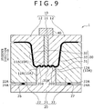
FIG. 9 is a view of a state where a protruded and recessed region is formed on the portion to be pressed. -
FIG. 10 is a view of a state where press forming for the portion to be pressed is completed. -
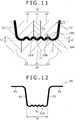
FIG. 11 is an enlarged view of a region XI inFIG. 10 . -
FIG. 12 is a view of a press-formed article according to the first embodiment of the present invention. -
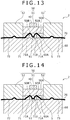
FIG. 13 is a view of the configuration of a press forming apparatus according to a second embodiment of the present invention. -
FIG. 14 is a view of a state where the press forming is applied to a portion to be pressed by the press forming apparatus. -
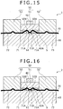
FIG. 15 is a view of a state where the press forming is applied to the portion to be pressed by the press forming apparatus. -
FIG. 16 is a view of a state where the press forming is applied to the portion to be pressed by the press forming apparatus. -
FIG. 17 is a view of a state where the press forming is applied to the portion to be pressed by the press forming apparatus. -
FIG. 18 is a view of a state where the press forming for the portion to be pressed is completed. -
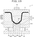
FIG. 19 is a view of the configuration of a press forming apparatus according to a third embodiment of the present invention. -
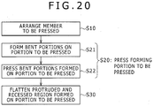
FIG. 20 is a flowchart of a manufacturing method of a press-formed article according to a fourth embodiment of the present invention. -
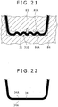
FIG. 21 is a view of a step of flattening a protruded and recessed region formed on a portion to be pressed. -
FIG. 22 is a view of a press-formed article including a flattened thickened portion. -
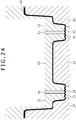
FIG. 23 is an enlarged view of a press forming apparatus according to another embodiment of the present invention. -
FIG. 24 is a view of a press forming apparatus according to another embodiment of the present invention: - Hereinafter, embodiments of the present invention will be described in detail with reference to drawings.
- First, a description is given of a configuration of a
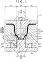
press forming apparatus 1 according to a first embodiment of the present invention mainly with reference toFIG. 1 . Thepress forming apparatus 1 is an apparatus for manufacturing a press-formed article in a hat shape in the cross sectional view by applying press forming to a portion to be pressed 31 in a bent shape formed on a member to be pressed 30 in a plate shape. On this occasion, the "portion to be pressed" is a portion to be deformed by the pressing on the member to be pressed. Thepress forming apparatus 1 includes afirst die 10, which is an upper die, asecond die 20, which is a lower die, and adriving section 40. Hereinafter, an up/down direction inFIG. 1 is simply referred to as "up/down direction". Note that the up/down direction does not always need to be the gravity direction. Thesecond die 20 opposes thefirst die 10 in the up/down direction. The drivingsection 40 moves thefirst die 10 so as to approach thesecond die 20 or so as to depart from thesecond die 20 in the up/down direction. - The member to be pressed 30 is a plate formed of a metal material such as hard steel, soft steel, aluminum, titanium, and copper. The member to be pressed 30 includes the portion to be pressed 31 to be thickened by the press forming and surrounding
portions portions first die 10 and thesecond die 20. - The portion to be pressed 31 has a curved shape curved into a trapezoidal shape in the cross sectional view as shown in
FIG. 1 . More specifically, the portion to be pressed 31 has the trapezoidal shape having a height H in the up/down direction, and includes a firstflat plate portion 31E, which is the upper base of the trapezoid, and secondflat plate portions flat plate portion 31E. The secondflat plate portions portions - A line length of the portion to be pressed 31 before the pressing is longer than a length along an undulation of a protruded and recessed
region 91A, described later, of a press-formedarticle 90 shown inFIG. 12 . On this occasion, the "line length" of the portion to be pressed 31 is a length from one end of the portion to be pressed 31 to the other end along the portion to be pressed 31, and a line length, which is a sum of the first and secondflat plate portions region 91A (in other words, so that the height H of the trapezoid disappears), the line length of the portion to be pressed 31 can be decreased, thereby thickening the portion to be pressed 31. In other words, the secondflat plate portions - The portion to be pressed 31 is configured to have such a curved shape, thereby sufficiently securing the line length required for the thickening. More specifically, a longer line length can be secured compared with the case where a
microbead 310A formed by a continuous protruded and recessed region is formed on a portion to be pressed 310 in a flat plate shape as shown in a comparative example ofFIG. 2 . In other words, the length (line length) from one end of the portion to be pressed 31 to the other end along the portion to be pressed 31 can be greatly increased, thereby increasing a thickened amount of the portion to be pressed 31 according to this embodiment compared with the comparative example in which themicrobead 310A is formed. Moreover, the shape of the portion to be pressed 31 is not limited to the trapezoidal shape in the cross sectional view as described above, may be a shape bent in a rectangular shape in the cross sectional view as inFIG. 3 , or may be bent in an arc (arch) shape in the cross sectional view as shown inFIG. 4 . - The
first die 10 includes an upperpress forming surface 10A in a wave shape for pressing one main surface of the portion to be pressed 31 as shown inFIG. 1 . Thefirst die 10 includes a firstdie center portion 11 arranged at the center of thefirst die 10 and firstdie surrounding portions 12 formed separately from the firstdie center portion 11, and arranged on respective sides of the firstdie center portion 11 so as to sandwich side surfaces of the firstdie center portion 11. The upperpress forming surface 10A is constructed by a first formingsurface 11A provided at a bottom end of the firstdie center portion 11 and second formingsurfaces 12A provided at respective bottom ends of the firstdie surrounding portions 12. Moreover, the upperpress forming surface 10A has a surface including a continuous protruded and recessed region by aligning the height of the first formingsurface 11A and the height of the second formingsurfaces 12A to each other as shown inFIG. 8 . - Moreover, the
first die 10 includes the upperpress forming surface 10A, and includes an upper formingdie portion 74, which is a portion for applying the press forming to the portion to be pressed 31, and upper sandwiching dieportions portions FIG. 1 . The upper formingdie portion 74 is formed integrally by the firstdie center portion 11 and parts of the firstdie surrounding portions 12. The upper sandwiching dieportions die surrounding portions 12. - The first
die center portion 11 and the firstdie surrounding portions 12 are configured to be moved by the drivingsection 40 in the up/down direction independently of each other. In other words, only the firstdie surrounding portions 12 can be moved in the up/down direction while the position of the firstdie center portion 11 is fixed, and only the firstdie center portion 11 can be moved in the up/down direction while the positions of the firstdie surrounding portions 12 are fixed. - A
pressing portion 14 in a shape protruding downward toward thesecond die 20 is provided on the first formingsurface 11A of the firstdie center portion 11. Thepressing portion 14 is a center portion of the first formingsurface 11A, and protrudes downward more than portions on both sides thereof. A secondbent portion 31B bending in a protruded shape toward thefirst die 10 is formed on the portion to be pressed 31 during the press forming as shown inFIG. 7 , and the secondbent portion 31B can be pressed by thepressing portion 14. - The
second die 20 includes a lowerpress forming surface 20A in a wave shape opposing the upperpress forming surface 10A of thefirst die 10 as shown inFIG. 1 . Thesecond die 20 includes a seconddie center portion 21, and seconddie surrounding portions 22 formed independently of the seconddie center portion 21. - The second
die center portion 21 includes asupport portion 24 placed on a horizontal surface, and a formingportion 25 standing upward from an approximate center of thesupport portion 24 toward thefirst die 10. The lowerpress forming surface 20A is provided on a top of the formingportion 25. The lowerpress forming surface 20A is formed of a continuous protruded and recessed region as the upperpress forming surface 10A, and has a length the same as the width of the protruded and recessedregion 91A formed on the press-formedarticle 90 shown inFIG. 12 . Moreover, protruded portions of the upperpress forming surface 10A oppose recessed portions of the lowerpress forming surface 20A, and recessed portions of the upperpress forming surface 10A oppose protruded portions of the lowerpress forming surface 20A. Therefore, a protruded and recessed region along the protruded and recessed surfaces of the upper and lowerpress forming surfaces press forming surface 10A and the lowerpress forming surface 20A to apply the press forming to the portion to be pressed 31 in the wave shape as shown inFIG. 9 . - Two first
bent portions 31A each bent in a protruded shape toward thesecond die 20 are formed on the portion to be pressed 31 so as to be separated from each other on the portion to be pressed 31 during the press forming as shown inFIG. 7 . The two firstbent portions 31A can be held by groove-shapedholding portions 20B in a pair provided on the lowerpress forming surface 20A. The holdingportions 20B are provided so as to be separated from each other, thereby positioning on respective sides of a recessed groove positioned at the center of the lowerpress forming surface 20A, and are positioned outside thepressing portion 14 of thefirst die 10. In other words, thepressing portion 14 is positioned between the two holdingportions 20B. - The second
die surrounding portions 22 are arranged so as to oppose the firstdie surrounding portions 12 in the up/down direction, and sandwich the surroundingportions die surrounding portions 12 as illustrated inFIG. 1 . Bottom end surfaces 22A of the seconddie surrounding portions 22 are connected to one ends ofelastic members die surrounding portions 22 are connected to atop surface 24A of thesupport portion 24 via theelastic members die surrounding portions 22 are positioned so as to form steps on a upper side with respect to the formingportion 25 of the seconddie center portion 21 in the state before the start of the pressing shown inFIG. 1 , and a press space S for storing the portion to be pressed 31 is formed between the upperpress forming surface 10A and the lowerpress forming surface 20A as a result. Then, the firstdie surrounding portions 12 move down, thereby downward pressing the seconddie surrounding portions 22, theelastic members die surrounding portions 22 move down while sliding over side surfaces of the formingportion 25. As a result, the press space S gradually decreases, and the portion to be pressed 31 is pressed. - In the
second die 20, the seconddie center portion 21 corresponds to a lower forming die portion for applying, together with the upper formingdie portion 74, the press forming to the portion to be pressed 31, and the seconddie surrounding portions 22 correspond to lower sandwiching die portions for sandwiching and fixing, together with the upper sandwiching dieportions portions - The driving
section 40 is used to move down thefirst die 10 so as to approach thesecond die 20. As a result, the press space S can be decreased, thereby applying the press forming to the portion to be pressed 31. The drivingsection 40 is arranged at a top portion of thefirst die 10, and includes a reciprocally movable hydraulic or electric piston. The firstdie center portion 11 and the firstdie surrounding portions 12 can be upward/downward moved independently of each other by using the piston to press these portions. - A description will now be given of a process of using the
press forming apparatus 1 to apply the press forming to the portion to be pressed 31 mainly referring to a flowchart shown inFIG. 5 andFIGS. 1 and6 to 10 .FIGS 1 and6 to 10 sequentially show a process of moving down thefirst die 10 toward thesecond die 20, thereby decreasing the press space S to apply the press forming to the portion to be pressed 31. Moreover, a description is given of the hot pressing for applying the press forming to the member to be pressed 30 softened by heating according to this embodiment, but this manufacturing method is not limited to the hot pressing, and can be similarly used for cold working. - First, the member to be pressed 30 in the flat plate shape formed of various metal materials such as hard steel is prepared, and the member to be pressed 30 is machined to form the portion to be pressed 31 bent in the trapezoidal shape. Then, the member to be pressed 30 is heated in an electric furnace, or is heated by supplying an electric current, thereby being brought into the softened state.
- Then, Step S10 for arranging the member to be pressed 30 in the
press forming apparatus 1 is carried out. In Step S10, the member to be pressed 30 softened by the heating is arranged between thefirst die 10 and thesecond die 20. On this occasion, as shown inFIG. 1 , the surroundingportions die surrounding portions 12 and the seconddie surrounding portions 22, and the portion to be pressed 31 is arranged in the press space S. - Then, Step S20 for applying the press forming to the member to be pressed 31 is carried out. In Step S20, the
first die 10 is moved so as to approach thesecond die 20 to decrease the press space S, thereby applying the press forming to the portion to be pressed 31 so that the height H of the portion to be pressed 31 decreases. In Step S20, a bending step S21 for forming the firstbent portions 31A and the secondbent portion 31B on the portion to be pressed 31 as shown inFIG. 7 , and a deformation step S22 for pressing the secondbent portion 31B to deform while the firstbent portion 31A are held by the holdingportions 20B as shown inFIG. 8 are carried out in sequence. - First, in the bending step S21, the first
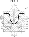
die surrounding portions 12 are moved downward toward the seconddie surrounding portions 22 by the drivingsection 40 while the position of the firstdie center portion 11 is fixed in the state ofFIG. 1 . As a result, the surroundingportions die surrounding portions 12 and the seconddie surrounding portions 22 as shown inFIG. 6 . As a result, a flow of the material toward the surroundingportions - In this state, the press space S is decreased by further moving downward the first
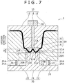
die surrounding portions 12, thereby gradually decreasing the height H of the portion to be pressed 31. Then, when the height H of the portion to be pressed 31 becomes equal to or less than a predetermined value, the portion to be pressed 31 bends, and the pair of firstbent portions 31A each bent in the protruded shape toward thesecond die 20 and the secondbent portion 31B bent in the protruded shape from the position between the pair of the firstbent portions 31A toward thefirst die 10 are formed on the portion to be pressed 31 as shown inFIG. 7 . On this occasion, the material between the holdingportions 20B and the surroundingportions portions 20B, and further flows from the holdingportions 20B toward thepressing portion 14 as the first die 10 approaches thesecond die 20 while the surroundingportions bent portions 31A swell out so as to fit into the recessed grooves of the holdingportions 20B, and are thus fixed in position as shown inFIG. 7 , and the secondbent portion 31B swells out upward so as to oppose thepressing portion 14 of thefirst die 10. - Then, both the first
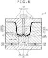
die center portion 11 and the firstdie surrounding portions 12 are moved downward by the drivingsection 40, and the secondbent portion 31B is pressed by thepressing portion 14 of thefirst die 10 while the firstbent portions 31A are held by the holdingportions 20B as shown inFIG. 8 in Step S22 for the deformation. As a result, the secondbent portion 31B deforms so as to bend downward. On this occasion, the material flows in the portion to be pressed 31, but a flow of the material toward the outsides of the holdingportions 20B (namely toward the surroundingportions 32 and 33) is suppressed by the firstbent portions 31A being held by the holdingportions 20B, and an excessive amount of the material is prevented from unevenly being distributed to the both sides of the portion to be pressed 31. Moreover, the material is also prevented from entering the surroundingportions portions die surrounding portions 12 and the seconddie surrounding portions 22. An excessive amount of the material is prevented from being unevenly distributed in the center portion of the portion to be pressed 31 by the secondbent portion 31B being pressed by thepressing portion 14. Then, the movements of the firstdie center portion 11 and the firstdie surrounding portions 12 are stopped when these portions are moved downward until the height H of the portion to be pressed 31 disappears as shown inFIGS. 9 and10 , and the press forming is completed. A distance L1 between thepressing portion 14 and a portion of thesecond die 20 opposing the pressing portion 14 (bottom surface of the recessed groove on the lowerpress forming surface 20A) and a distance L2 between the bottom surface of the holdingportion 20B and a portion of thefirst die 10 opposing the bottom surface of the holdingportion 20B (the protruded portion on the upperpress forming surface 10A) are the same when the pressing is completed as shown in an enlarged view inFIG. 11 . - As described above, the portion to be pressed 31 is thickened as the height H decreases by applying the press forming to the portion to be pressed 31 in the height direction (namely, the up/down direction) while the material is prevented from flowing toward the surrounding
portions portions 32 and 33 (portions other than the portion to be pressed 31), resulting in manufacturing of a partially thickened press-formed article as shown inFIG. 11 . On this occasion, the plate thicknesses T1 and T2 are respectively the thinnest plate thicknesses (lowest plate thicknesses) of the portion to be pressed 31 and the surroundingportions region 91A in the shape along the protruded and recessed surfaces of the upper and lowerpress forming surfaces first die 10 is moved upward by the drivingsection 40, and the press-formed article is taken out after the press forming is completed in this way. - A description will now be given of the press-formed
article 90 according to this embodiment referring toFIG. 12 . The press-formedarticle 90 is a component used as a frame member of an automobile such as a front pillar, a cross member, and a side sill, and is manufactured by the manufacturing method of a press-formed article according to this embodiment. - The press-formed
article 90 has the shape machined into the hat shape, and includes atop plate portion 91 thickened by the press forming applied to the portion to be pressed 31,vertical wall portions top plate portion 91, andflange portions vertical wall portions FIG. 12 . Thevertical wall portions flange portions portions 32 and 33 (seeFIG. 1 .), and are less in the plate thickness than thetop plate portion 91. In other words, the press-formedarticle 90 is partially thickened at thetop plate portion 91. Moreover, the continuous protruded and recessedregion 91A is formed so as to follow the protruded and recessed surfaces of thepress forming surfaces first die 10 and thesecond die 20 on the top plate portion 91 (thickened portion) as shown inFIG. 12 . This protruded and recessedregion 91A is a portion in a wave shape formed so as to repeat in a sufficiently small width than a width W in the left/right direction inFIG. 12 of thetop plate portion 91. The strength in the thickenedportion 91 is increased by providing the protruded and recessedregion 91A compared with a case where the region is in a flat surface shape. - A description will now be given of characteristics and operations/effects of a
press forming apparatus 1 and the manufacturing method of a press-formed article according to this embodiment. - The
press forming apparatus 1 is an apparatus for manufacturing the press-formedarticle 90 by applying the press forming to the portion to be pressed 31 in the bent shape (curved shape) formed on the member to be pressed 30 in the plate shape. Thepress forming apparatus 1 includes thefirst die 10 that has the upperpress forming surface 10A, thesecond die 20 that has the lowerpress forming surface 20A opposing the upperpress forming surface 10A, and forms the press space S for storing the portion to be pressed 31 in the gap with thefirst die 10, and the drivingsection 40 that relatively moves thefirst die 10 and thesecond die 20 so as to approach each other, thereby decreasing the press space S. The groove-shapedholding portions 20B are provided on thesecond die 20 so as to be separated from each other for holding the two firstbent portions 31A on the portion to be pressed 31. Thefirst die 10 includes thepressing portion 14 that is positioned between the two holdingportions 20B, has the shape protruding toward thesecond die 20, and presses the secondbent portion 31B on the portion to be pressed 31. - The manufacturing method of a press-formed article is the method of manufacturing the press-formed
article 90 by applying the press forming to the portion to be pressed 31 in the curved shape formed on the member to be pressed 30 in the plate shape. The manufacturing method includes Step S10 of arranging the member to be pressed 30 between thefirst die 10 and thesecond die 20, and Step S20 for relatively moving thefirst die 10 and thesecond die 20 so as to approach each other, thereby applying the press forming to the portion to be pressed 31 so that the height H of the portion to be pressed 31 decreases. In Step S20 for applying the press forming, while the pair of firstbent portions 31A each bent in the protruded shape toward thesecond die 20 on the portion to be pressed 31 are held by the pair of holdingportions 20B each in the groove shape provided so as to be separated from each other on thesecond die 20, the secondbent portion 31B bent in the protruded shape from the position between the firstbent portions 31A toward thefirst die 10 on the portion to be pressed 31 is pressed by thepressing portion 14 of thefirst die 10, thereby deforming the secondbent portion 31B so as to thicken the portion to be pressed 31. - With the above-mentioned characteristic, the thickened portion can be formed by constructing the portion to be pressed 31 in the bent shape so as to secure the line length required for the thickening, and applying the press forming so as to decrease the height H of the portion to be pressed 31. Therefore, a longer line length required for the thickening can be secured compared with the case of the comparative example shown in
FIG. 2 where themicrobead 310A is formed on the portion to be pressed 310 in the flat plate shape, and the press-formedarticle 90 more in the thickened amount can be manufactured. Moreover, the secondbent portion 31B provided between the firstbent portions 31A is pressed by thepressing portion 14 of thefirst die 10 while the firstbent portions 31A are held by the holdingportions 20B of thesecond die 20 during the press forming of the portion to be pressed 31. As a result, the material can be prevented from unevenly being distributed to the both sides or the center portion of the portion to be pressed 31. An intended thickened amount can be obtained, and a local thinning that may be a start point of a crack in the press-formedarticle 90 can be prevented by controlling the flow of the material during the press forming in this way. As a result, the press-formed article in a desired shape can appropriately be obtained. - In the manufacturing method of a press-formed article, in Step S20 for applying the press forming, the press forming is applied to the portion to be pressed 31 so as to increase in the plate thickness more than the potions (surrounding
portions 32 and 33) other than the portion to be pressed 31 in the member to be pressed 30. As a result, the press-formedarticle 90 increased in the strength can be manufactured by partially forming the thickened portion. - In the manufacturing method of a press-formed article, in Step S20 for applying the press forming, the press forming is applied to the portion to be pressed 31 until the height H of the portion to be pressed 31 disappears after the forming, in other words, the ends of the surrounding
portions article 90 increased more in the strength can be manufactured. - In the manufacturing method of a press-formed article, the member to be pressed 30 includes the surrounding
portions portions - In the manufacturing method of a press-formed article, in Step S20 for applying the press forming, the first
bent portions 31A and the secondbent portion 31B are formed on the portion to be pressed 31. More specifically, Step S20 for applying the press forming includes the bending step S21 for forming the firstbent portions 31A and the secondbent portion 31B on the portion to be pressed 31, and the deformation step S22 for pressing and deforming the secondbent portion 31B while the firstbent portions 31A are held by the holdingportions 20B. The formation of the first and secondbent portions bent portions - In the manufacturing method of a press-formed article, the
first die 10 includes the firstdie center portion 11 including thepressing portion 14, and the firstdie surrounding portions 12 formed independently of the firstdie center portion 11, and configured to move independently of the firstdie center portion 11. In Step S20 for applying the press forming, after the firstbent portions 31A and the secondbent portion 31B are formed on the portion to be pressed 31 by moving the firstdie surrounding portions 12, the secondbent portion 31B is pressed and deformed by thepressing portion 14. More specifically, in Step S21 for the bending, the firstbent portions 31A and the secondbent portion 31B are formed on the portion to be pressed 31 by moving downward the firstdie surrounding portions 12. Then, the secondbent portion 31B is pressed and deformed by thepressing portion 14 by downward moving the firstdie center portion 11 in Step S22 for the deformation. As a result, the firstdie center portion 11 can be started to move after the secondbent portion 31B is formed on the portion to be pressed 31 during the press forming, thereby using thepressing portion 14 to surely press the secondbent portion 31B. - In the manufacturing method of a press-formed article, the distance L1 between the
pressing portion 14 and thesecond die 20 and the distance L2 between the holdingportions 20B and thefirst die 10 are the same when Step S20 for the press forming is completed. As a result, the thickness of the portion to be pressed 31 can be uniform. - In the manufacturing method of a press-formed article, in Step S20 for applying the press forming, the protruded and recessed
region 91A is provided on the portion to be pressed 31. As a result, the press-formedarticle 90 reinforced by the protruded and recessedregion 91A and thus increased in the strength can be manufactured. - In the manufacturing method of a press-formed article, the member to be pressed 30 may be formed by the hot pressing. The flow of the material in the portion to be pressed 31 can be controlled according to this embodiment as described above, and the intended thickened amount can be thus obtained even in the case of the hot pressing in which the material is likely to flow during the press forming.
- The protruded and recessed
region 91A can be provided without changing the plate thickness of the portion to be pressed 31 before and after the pressing in Step S22 for the deformation according to the first embodiment. The strength of the press-formed article can be secured by providing the protruded and recessedregion 91A even in this case. The same holds true for the following embodiments. It should be noted that a height in the up/down direction (refer toFIG. 9 ) of a protruded and recessed portion of the protruded and recessedregion 91A, namely a distance between a top and a bottom, is more than that in the case where the portion to be pressed 31 is thickened. The portion to be pressed 31 only needs not to be decreased in the plate thickness by the press forming in this way, and the press forming may be applied for the thickening as in the first embodiment, or the press forming may be applied so as to maintain a constant plate thickness of the portion to be pressed 31. - A description will now be given of a
press forming apparatus 2 and a manufacturing method of a press-formed article according to a second embodiment of the present invention with reference toFIGS. 13 to 18 . It should be noted that only points different from the first embodiment will be detailed in the second embodiment. - The
press forming apparatus 2 is an apparatus for manufacturing a press-formed article by applying the press forming to a portion to be pressed 71 bent in an M shape in the cross sectional view formed on a member to be pressed 70 in a plate shape as shown inFIG. 13 . The line length of the portion to be pressed 71 is more than the length along the protruded and recessedregion 91A on the press-formedarticle 90 shown inFIG. 12 as in the first embodiment. Thepress forming apparatus 2 includes anupper die 50, alower die 60, and the drivingsection 40. Apressing portion 61 is provided on thelower die 60 as described later according to the second embodiment, and thelower die 60 corresponds to thefirst die 10 on which thepressing portion 14 shown inFIG. 1 is provided. Thelower die 60 is referred to as "first die 60" hereinafter. Holdingportions 50B are provided on theupper die 50, and theupper die 50 corresponds to thesecond die 20 on which the holdingportions 20B shown inFIG. 1 are provided. Theupper die 50 is referred to as "second die 50" hereinafter. The drivingsection 40 moves thesecond die 50 so as to approach thefirst die 60 or so as to depart from thefirst die 60 in the up/down direction. In other words, thesecond die 50 is moved upward/downward while the position of thefirst die 60 is fixed according to the second embodiment, which is different from the first embodiment. - The
second die 50 includes a seconddie center portion 51 in a block shape on which an upperpress forming surface 50A in a wave shape is formed and seconddie surrounding portions 52 each in a block shape arranged so as to sandwich both side surfaces of the seconddie center portion 51. The drivingsection 40 is arranged on a top portion of the seconddie center portion 51, and the seconddie center portion 51 is configured to be upward/downward moved by the drivingsection 40. The upperpress forming surface 50A is constructed by a continuous protruded and recessed region, and two recessed grooves constitute the holdingportions 50B provided so as to be separated from each other, thereby existing on both sides of a center recessed groove. Two firstbent portions 71A formed on the portion to be pressed 71 can be held by the holdingportions 50B. The seconddie center portion 51 corresponds to the upper forming die portion and the seconddie surrounding portions 52 correspond to the upper sandwiching die portions according to this embodiment. - The
first die 60 includes a lowerpress forming surface 60A in a wave shape opposing the upperpress forming surface 50A. The portion to be pressed 71 is stored in the press space S formed between the upperpress forming surface 50A and the lowerpress forming surface 60A, and surroundingportions die surrounding portions 52 and thefirst die 60. The lowerpress forming surface 60A includes apressing portion 61 in a shape protruding toward thesecond die 50 at its center, and can use thepressing portion 61 to press a secondbent portion 71B formed on the portion to be pressed 71. Thepressing portion 61 is a part of thefirst die 60 according to this embodiment, and thepressing portion 61 integrally moves with other die portions, which is different from the first embodiment. - Moreover, a portion on which the lower
press forming surface 60A is formed at the center portion of thefirst die 60 corresponds to the lower forming die portion, and portions on both sides thereof correspond to the lower sandwiching die portions according to this embodiment. In other words, the lower forming die portion and the lower sandwiching die portions are integrally formed as the singlefirst die 60 according to this embodiment, which is different from the first embodiment. - A description will now be given of the manufacturing method of a press-formed article carried out by using the
press forming apparatus 2. - First, the member to be pressed 70, on which the first
bent portions 71A and the secondbent portion 71B are formed in advance by bending on the portion to be pressed 71, is prepared, is brought into a softened state by heating, and then is arranged between thesecond die 50 and thefirst die 60 as shown inFIG. 13 in Step S10 (seeFIG. 5 .). On this occasion, the portion to be pressed 71 is positioned in the press space S, and the surroundingportions die surrounding portion 52 and thefirst die 60. Moreover, there is brought about such a state that the firstbent portions 71A are fit into the holdingportions 50B of thesecond die 50, and the secondbent portion 71B abuts against thepressing portion 61 of thefirst die 60. - Then, the press space S is decreased by using the
driving section 40 to move down the seconddie center portion 51 toward thefirst die 60 in Step S20 (seeFIG. 5 .). As a result, the height H of the portion to be pressed 71 gradually decreases, thereby increasing the thickness of the portion to be pressed 71 in the state where the surroundingportions FIGS. 14 to 18 . On this occasion, a flow of an excessive amount of the material to outsides of the firstbent portions 71A is suppressed by the firstbent portions 71A being held by the holdingportions 50B, and a distribution of an excessive amount of the material to the portion between the firstbent portions 71A is suppressed by the secondbent portion 71B being pressed by thepressing portion 61 as in the first embodiment. As a result, the press-formed article in the flat plate shape including the thickened portion on which the continuous protruded and the recessed region is formed is manufactured as shown inFIG. 18 . - The member to be pressed 70 on which the first
bent portions 71A and the secondbent portion 71B are formed in advance on the portion to be pressed 71 is prepared, and the press-formed article is manufactured by applying the press forming to the member to be pressed 70 according to the second embodiment in this way. The firstbent portions 71A can surely be formed at the positions opposing the holdingportions 50B of thesecond die 50, and the secondbent portion 71B can surely be formed at the position opposing thepressing portion 61 of thefirst die 60 by forming the first and secondbent portions bent portions 71A can more surely be held by the holdingportions 50B, and the secondbent portion 71B can more surely be pressed by thepressing portion 61 during the press forming. - It should be noted that the
pressing portion 61 may be in contact with the secondbent portion 71B in the state before the start of the pressing as shown inFIG. 13 , but the configuration is not limited to this case, a gap may be formed between thepressing portion 61 and the secondbent portion 71B in the state before the start of the press, and thepressing portion 61 may be brought in contact with the secondbent portion 71B by moving down the seconddie center portion 51 during the pressing. - A description will now be given of a
press forming apparatus 3 and a manufacturing method of a press-formed article according to a third embodiment of the present invention with reference toFIG. 19 . It should be noted that only points different from the first embodiment will be detailed in the third embodiment. - A first die 15 (upper die) includes an upper
press forming surface 15A in a wave shape, and the upperpress forming surface 15A has a protruded shape at a center swelling out toward a second die center portion 28 (second die) in thepress forming apparatus 3 as shown inFIG. 19 . Apressing portion 15B is provided at a top of the upperpress forming surface 15A as in the first embodiment. Moreover, the seconddie center portion 28 includes a lowerpress forming surface 28A in a wave shape opposing the upperpress forming surface 15A, and the lowerpress forming surface 28A has a recessed shape so as to depart from thefirst die 15. Continuous protruded and recessed regions are formed on the upper and lowerpress forming surfaces portions 28B is provided so as to be separated from each other on the lowerpress forming surface 28A as in the first embodiment. - The member to be pressed 30 is arranged so that the portion to be pressed 31 is positioned between the upper and lower
press forming surfaces portions first die 15 and the seconddie surrounding portions 29, and the press forming is applied to the portion to be pressed 31 by moving down thefirst die 15 in thepress forming apparatus 3. As a result, the press forming is applied to the portion to be pressed 31 so as to have abent shape 31G in a protruded shape toward the seconddie center portion 28 along the shapes of the upper and lowerpress forming surfaces bent shape 31G is a shape curved so as to protrude toward the seconddie center portion 28 as shown inFIG. 19 . Moreover, the protruded and recessedregion 91A is simultaneously formed on thebent shape 31G. On this occasion, a height H1 of the portion to be pressed 31 after the forming is less than the height H (FIG. 1 ) of the portion to be pressed 31 in a trapezoidal shape before the forming. Moreover, a width of thebent shape 31G in the left/right direction ofFIG. 19 is more than a width of the protruded and recessedregion 91A. The press-formed article bent in the thickened portion can be manufactured by using the dies on which thepress forming surfaces first die 15 conversely in this embodiment. - A description will now be given of a manufacturing method of a press-formed article according to a fourth embodiment of the present invention with reference to a flowchart in
FIG. 20 . After Step S10 of arranging the member to be pressed 30 and Step S20 for applying the press forming to the portion to be pressed 31 are sequentially carried out as in the first embodiment, Step S30 of flattening the protruded and recessed region of the portion to be pressed 31 is further carried out according to the fourth embodiment as shown inFIG. 20 . - Specifically, the protruded and recessed
region 31D can be flattened by arranging the portion to be pressed 31 on which the continuous protruded and recessedregion 31D is formed between dies 83 and 84 includingpress forming surfaces press forming surfaces FIG. 21 . As a result, a press-formed article including a thickenedportion 34 on which the protruded and recessed region disappears, and aflat surface 34A is formed can be manufactured as shown inFIG. 22 . The plate material can be prevented from being buckled by flattening the protruded and recessedregion 31D after once forming the protruded and recessedregion 31D on the portion to be pressed 31 in this way, which is different from the case where the portion to be pressed 31 is directly formed into the flat shape. A step of using dies and the like to press and flatten the protruded and recessedregion 91A in the thickness direction after the protruded and recessedregion 91A is formed on thebent shape 31G may be carried out also according to the third embodiment as in the fourth embodiment. - Finally, a description is given of other embodiments of the present invention.
- The protruded and recessed shapes on the upper
press forming surface 10A of thefirst die 10 and the lowerpress forming surface 20A of thesecond die 20 may be left-right asymmetric in the cross sectional view as shown inFIG. 23 . In other words, the width of the recessed grooves may not be the same over the entire surface. Moreover, a plurality (two) of portions to be pressed 31 may be formed on the member to be pressed 30, and a press-formed article on which a plurality of thickened portions are formed may be manufactured by applying the press forming to the portions to be pressed 31 as shown inFIG. 24 . The number of provided portions to be pressed 31 may be equal to or more than three. - The portion to be pressed is not necessarily be uniformly thickened as long as the desired strength is provided for the press-formed article according to the first embodiment. The same holds true for the other embodiments.
- The configuration according to the first embodiment is not limited to the case where the second
bent portion 31B is formed at the center of the portion to be pressed 31, and the secondbent portion 31B may be formed at a position closer to one of the ends of the portion to be pressed 31 rather than at the center thereof. Moreover, the configuration is not limited to the case where only the pair of firstbent portions 31A and the one secondbent portion 31B positioned therebetween are formed on the portion to be pressed 31, and a plurality of pairs of firstbent portions 31A and the secondbent portions 31B respectively positioned therebetween may be formed. - The configuration according to the first embodiment is not limited to the case where only the
first die 10 moves, and thesecond die 20 may move upward, or both thefirst die 10 and thesecond die 20 may move. The firstdie center portion 11 and the firstdie surrounding portions 12 may be integrated with each other. - It should be considered that the embodiments disclosed herein are exemplary in all respects, and are not limitative. The scope of the present invention is not represented by the above description but by the scope of claims, and it is intended that connotation equivalent to the scope of claims, and all changes within the scope are included.
Claims (15)
- A method of manufacturing a press-formed article by press forming a bent-shaped portion to be pressed that is formed on a plate-shaped member to be pressed comprising the steps of:arranging the member to be pressed between a first die and a second die; andpress forming the portion to be pressed so that a height of the portion to be pressed decreases by moving the first die and the second die relative to each other so as to approach each other,wherein in the press forming step, while first bent portions in a pair each bent in a protruded shape toward the second die on the portion to be pressed are held by groove-shaped holding portions in a pair provided so as to be separated from each other on the second die, a second bent portion bent in a protruded shape from a position between the first bent portions toward the first die on the portion to be pressed is pressed and deformed by a pressing portion of the first die.
- The method of manufacturing a press-formed article according to claim 1,
wherein in the press forming step, the portion to be pressed is thickened. - The method of manufacturing a press-formed article according to claim 1 or 2,
wherein in the press forming step, the portion to be pressed is press formed until the height of the portion to be pressed disappears after the press forming. - The method of manufacturing a press-formed article according to any one of preceding claims,
wherein in the press forming step, the portion to be pressed is press formed so that the portion to be pressed after the press forming has a bent shape less in the height than that before the press forming. - The method of manufacturing a press-formed article according to any one of preceding claims,
wherein in the press forming step, a surrounding portion of the portion to be pressed out of the member to be pressed is sandwiched by the first die and the second die. - The method of manufacturing a press-formed article according to any one of preceding claims,
wherein in the press forming step, the first bent portions and the second bent portion are formed on the portion to be pressed. - The method of manufacturing a press-formed article according to any one of preceding claims,
wherein the first die includes a first die center portion including the pressing portion, and a first die surrounding portion formed separately from the first die center portion and configured to move independently of the first die center portion, and
wherein in the press forming step, after the first die surrounding portion is moved toward the second die to form the first bent portions and the second bent portion on the portion to be pressed, the second bent portion is pressed and deformed by the pressing portion. - The method of manufacturing a press-formed article according to any one of preceding claims,
wherein in the press forming step, the portion to be pressed on which the first bent portions and the second bent portion are formed in advance is press formed. - The method of manufacturing a press-formed article according to any one of preceding claims,
wherein a distance between the pressing portion and the second die and a distance between the holding portions and the first die are the same when the press forming step is completed. - The method of manufacturing a press-formed article according to any one of preceding claims,
wherein in the press forming step, a protruded and recessed region is provided on the portion to be pressed. - The method of manufacturing a press-formed article according to claim 10, further comprising the step of:flattening the protruded and recessed region after the press forming step.
- The method of manufacturing a press-formed article according to any one of preceding claims,
wherein the member to be pressed is formed by hot pressing. - A press-formed article manufactured by the method of manufacturing a press-formed article according to any one of preceding claims.
- A press forming apparatus manufacturing a press-formed article by press forming a bent-shaped portion to be pressed that is formed on a plate-shaped member to be pressed, comprising:a first die that includes a press forming surface;a second die that includes a press forming surface opposing the press forming surface and forms a press space between the first die and the second die in which the portion to be pressed is stored; anda driving section that moves the first die and the second die relative to each other so as to approach each other, thereby decreasing the press space,wherein groove-shaped holding portions in a pair are provided on the second die so as to be separated from each other and to hold two first bent portions on the portion to be pressed, andwherein the first die includes a pressing portion that is positioned between the two holding portions, has a shape protruding toward the second die, and presses a second bent portion on the portion to be pressed.
- The press forming apparatus according to claim 14,
wherein the first die includes a first die center portion including the pressing portion, and a first die surrounding portion formed separately from the first die center portion and configured to move independently of the first die center portion.
Applications Claiming Priority (1)
| Application Number | Priority Date | Filing Date | Title |
|---|---|---|---|
| JP2016015907A JP6659380B2 (en) | 2016-01-29 | 2016-01-29 | Method for manufacturing press-formed product and press-forming apparatus |
Publications (2)
| Publication Number | Publication Date |
|---|---|
| EP3199256A1 true EP3199256A1 (en) | 2017-08-02 |
| EP3199256B1 EP3199256B1 (en) | 2019-03-13 |
Family
ID=57868010
Family Applications (1)
| Application Number | Title | Priority Date | Filing Date |
|---|---|---|---|
| EP17000007.9A Active EP3199256B1 (en) | 2016-01-29 | 2017-01-03 | Manufacturing method of press-formed article and press forming apparatus |
Country Status (4)
| Country | Link |
|---|---|
| US (1) | US10300519B2 (en) |
| EP (1) | EP3199256B1 (en) |
| JP (1) | JP6659380B2 (en) |
| CN (1) | CN107020335B (en) |
Cited By (4)
| Publication number | Priority date | Publication date | Assignee | Title |
|---|---|---|---|---|
| EP3588747A4 (en) * | 2017-10-13 | 2020-04-22 | Wei Zhu | Motor housing produced by using titanium |
| EP3646961A1 (en) * | 2017-06-28 | 2020-05-06 | Kabushiki Kaisha Kobe Seiko Sho (Kobe Steel, Ltd.) | Method for manufacturing press molded product |
| EP3778053A4 (en) * | 2018-03-28 | 2021-05-19 | JFE Steel Corporation | Designing method for press-molded article, press-molding die, press-molded article, and production method for press-molded article |
| CN114101474A (en) * | 2020-08-31 | 2022-03-01 | 宝山钢铁股份有限公司 | Two-pass forming processing method for convex hull of module backboard |
Families Citing this family (9)
| Publication number | Priority date | Publication date | Assignee | Title |
|---|---|---|---|---|
| CA3030104A1 (en) * | 2016-07-13 | 2018-01-18 | Nippon Steel & Sumitomo Metal Corporation | Hot-stamping formed article, vehicle member, and manufacturing method of hot-stamping formed article |
| JP7017944B2 (en) * | 2018-02-09 | 2022-02-09 | 株式会社三井ハイテック | Manufacturing method of metal molded body |
| CN108817230B (en) * | 2018-07-19 | 2019-12-03 | 安徽江淮汽车集团股份有限公司 | A kind of mould structure |
| JP6677289B1 (en) * | 2018-12-12 | 2020-04-08 | Jfeスチール株式会社 | Press molding method |
| JP2020146747A (en) * | 2019-03-15 | 2020-09-17 | 本田技研工業株式会社 | Manufacturing method for vehicle body frame and vehicle body frame |
| JP7110144B2 (en) * | 2019-03-15 | 2022-08-01 | 本田技研工業株式会社 | Manufacturing method of body frame |
| CN112676416B (en) * | 2019-10-17 | 2023-05-05 | 本田技研工业株式会社 | Method for manufacturing vehicle body skeleton member |
| CN110993128A (en) * | 2019-12-02 | 2020-04-10 | 吉林农业大学 | Grillwork for pressurized water reactor fuel assembly |
| CN111940605B (en) * | 2020-08-04 | 2022-09-23 | 惠州融汇科技有限公司 | New energy automobile battery box top cap shaping structure |
Citations (6)
| Publication number | Priority date | Publication date | Assignee | Title |
|---|---|---|---|---|
| JP2010120062A (en) * | 2008-11-20 | 2010-06-03 | Nissan Motor Co Ltd | Method and apparatus for manufacturing press formed product, and the press formed product |
| JP2011161941A (en) | 2010-02-04 | 2011-08-25 | Toyota Motor Corp | Skeleton member and method for manufacturing skeleton member |
| EP2711104A1 (en) * | 2011-05-20 | 2014-03-26 | Nippon Steel & Sumitomo Metal Corporation | Press-molding method, and vehicle component |
| WO2014208244A1 (en) * | 2013-06-25 | 2014-12-31 | 日産自動車株式会社 | Device and method for forming thin-plate substrate |
| JP2015150601A (en) * | 2014-02-17 | 2015-08-24 | トヨタ自動車株式会社 | Thickness increasing method for press parts and vehicle press parts |
| WO2015147297A1 (en) * | 2014-03-28 | 2015-10-01 | 新日鐵住金株式会社 | Method for manufacturing sheet-shaped formed component having multiple sections of increased thickness, and sheet-shaped formed component having multiple sections of increased thickness |
Family Cites Families (13)
| Publication number | Priority date | Publication date | Assignee | Title |
|---|---|---|---|---|
| USRE16115E (en) * | 1925-07-14 | Poration | ||
| US1771028A (en) * | 1928-12-31 | 1930-07-22 | Kewanee Boiler Corp | Method of corrugating metal boiler sheets |
| SE463082B (en) * | 1986-10-24 | 1990-10-08 | Nordisk Kartro Ab | DEVICE FOR PROFILING A STEP FORMATED MATERIAL COVER |
| FR2660220B1 (en) * | 1990-04-03 | 1995-02-24 | Lorraine Laminage | PROCESS AND DEVICE FOR FORMING A RELIEF PART ON A SHEET OF SHEET AND PRODUCT OBTAINED ACCORDING TO THIS PROCESS. |
| JPH05154572A (en) * | 1991-12-03 | 1993-06-22 | Matsushita Electric Ind Co Ltd | Forming method and mold for forming |
| JP3950023B2 (en) * | 2002-08-21 | 2007-07-25 | 中央精機株式会社 | Manufacturing method of wheel disc for automobile |
| JP4418168B2 (en) * | 2003-05-14 | 2010-02-17 | 本田技研工業株式会社 | Manufacturing method of elliptical ring |
| JP2009072801A (en) * | 2007-09-19 | 2009-04-09 | Topre Corp | Method and device for partially thickening hot-pressed component |
| JP2011005552A (en) * | 2008-09-01 | 2011-01-13 | Mazda Motor Corp | Method of manufacturing member having closed cross section made of metal |
| JP5515279B2 (en) * | 2008-11-20 | 2014-06-11 | 日産自動車株式会社 | Press-molded product, press-molded product manufacturing method and manufacturing apparatus |
| JP5416498B2 (en) * | 2009-07-23 | 2014-02-12 | 本田技研工業株式会社 | Method and apparatus for forming tailored blank plate |
| JP6073194B2 (en) | 2013-07-03 | 2017-02-01 | 昭和電工株式会社 | Magnetic recording medium, magnetic storage device |
| CN204770231U (en) * | 2015-07-18 | 2015-11-18 | 宁波永诚五金机械有限公司 | Expansion sleeve's production mould |
-
2016
- 2016-01-29 JP JP2016015907A patent/JP6659380B2/en active Active
- 2016-12-01 US US15/366,989 patent/US10300519B2/en active Active
- 2016-12-29 CN CN201611248434.9A patent/CN107020335B/en active Active
-
2017
- 2017-01-03 EP EP17000007.9A patent/EP3199256B1/en active Active
Patent Citations (6)
| Publication number | Priority date | Publication date | Assignee | Title |
|---|---|---|---|---|
| JP2010120062A (en) * | 2008-11-20 | 2010-06-03 | Nissan Motor Co Ltd | Method and apparatus for manufacturing press formed product, and the press formed product |
| JP2011161941A (en) | 2010-02-04 | 2011-08-25 | Toyota Motor Corp | Skeleton member and method for manufacturing skeleton member |
| EP2711104A1 (en) * | 2011-05-20 | 2014-03-26 | Nippon Steel & Sumitomo Metal Corporation | Press-molding method, and vehicle component |
| WO2014208244A1 (en) * | 2013-06-25 | 2014-12-31 | 日産自動車株式会社 | Device and method for forming thin-plate substrate |
| JP2015150601A (en) * | 2014-02-17 | 2015-08-24 | トヨタ自動車株式会社 | Thickness increasing method for press parts and vehicle press parts |
| WO2015147297A1 (en) * | 2014-03-28 | 2015-10-01 | 新日鐵住金株式会社 | Method for manufacturing sheet-shaped formed component having multiple sections of increased thickness, and sheet-shaped formed component having multiple sections of increased thickness |
Cited By (6)
| Publication number | Priority date | Publication date | Assignee | Title |
|---|---|---|---|---|
| EP3646961A1 (en) * | 2017-06-28 | 2020-05-06 | Kabushiki Kaisha Kobe Seiko Sho (Kobe Steel, Ltd.) | Method for manufacturing press molded product |
| EP3646961A4 (en) * | 2017-06-28 | 2021-03-10 | Kabushiki Kaisha Kobe Seiko Sho (Kobe Steel, Ltd.) | Method for manufacturing press molded product |
| EP3588747A4 (en) * | 2017-10-13 | 2020-04-22 | Wei Zhu | Motor housing produced by using titanium |
| US10938264B2 (en) | 2017-10-13 | 2021-03-02 | Wei Zhu | Motor housing made of titanium |
| EP3778053A4 (en) * | 2018-03-28 | 2021-05-19 | JFE Steel Corporation | Designing method for press-molded article, press-molding die, press-molded article, and production method for press-molded article |
| CN114101474A (en) * | 2020-08-31 | 2022-03-01 | 宝山钢铁股份有限公司 | Two-pass forming processing method for convex hull of module backboard |
Also Published As
| Publication number | Publication date |
|---|---|
| US20170216901A1 (en) | 2017-08-03 |
| CN107020335B (en) | 2019-08-20 |
| US10300519B2 (en) | 2019-05-28 |
| CN107020335A (en) | 2017-08-08 |
| EP3199256B1 (en) | 2019-03-13 |
| JP6659380B2 (en) | 2020-03-04 |
| JP2017131960A (en) | 2017-08-03 |
Similar Documents
| Publication | Publication Date | Title |
|---|---|---|
| EP3199256B1 (en) | Manufacturing method of press-formed article and press forming apparatus | |
| RU2674059C2 (en) | Method of manufacturing, device for manufacturing and production line for manufacturing stamped parts | |
| US10220427B2 (en) | Press-molding apparatus, press-molding method, and press-molded product | |
| JP6028885B1 (en) | Press molding method and press molding apparatus | |
| JP5835768B2 (en) | Manufacturing method of frame parts | |
| KR101579028B1 (en) | Method for manufacturing closed-structure part and apparatus for the same | |
| US20190105697A1 (en) | Press-molded product, press-molded product producing method, and press-molded product producing apparatus | |
| CA2920874C (en) | Method and press-forming apparatus for manufacturing structural member for automotive body | |
| EP2857117B1 (en) | Method of forming structure having closed cross section, and device for forming structure having closed cross section | |
| JP4198445B2 (en) | Method and apparatus for manufacturing load receiving article for vehicle | |
| TW201819063A (en) | Method and device for manufacturing press formed article | |
| JPWO2015040969A1 (en) | PRESS-MOLDED PRODUCT, PRESS-MOLDED PRODUCTION METHOD, AND PRESS-MOLDED PRODUCTION DEVICE | |
| JP7004658B2 (en) | Bending method | |
| CN110769948B (en) | Method for producing press-molded article | |
| US20180361461A1 (en) | Manufacturing method of press-molded article and press molding apparatus | |
| JP2013103226A (en) | Bend straightening device for sheet metal | |
| JP2008189311A (en) | Load receiving article for vehicle | |
| KR101848411B1 (en) | Manufacturing apparatus and method for automotive bumper beam | |
| US20220055085A1 (en) | Press forming method | |
| JP2010149179A (en) | Method and apparatus of manufacturing press-formed article, and press-formed article | |
| JP6550322B2 (en) | Method of manufacturing press-formed product and press forming apparatus | |
| JP3931736B2 (en) | Press mold | |
| JP7246227B2 (en) | Press molding method and metal plate | |
| JP2022139485A (en) | Method and facility for manufacturing press molded article | |
| JP2022116608A (en) | Press molding method and press molding die |
Legal Events
| Date | Code | Title | Description |
|---|---|---|---|
| PUAI | Public reference made under article 153(3) epc to a published international application that has entered the european phase |
Free format text: ORIGINAL CODE: 0009012 |
|
| STAA | Information on the status of an ep patent application or granted ep patent |
Free format text: STATUS: THE APPLICATION HAS BEEN PUBLISHED |
|
| AK | Designated contracting states |
Kind code of ref document: A1 Designated state(s): AL AT BE BG CH CY CZ DE DK EE ES FI FR GB GR HR HU IE IS IT LI LT LU LV MC MK MT NL NO PL PT RO RS SE SI SK SM TR |
|
| AX | Request for extension of the european patent |
Extension state: BA ME |
|
| STAA | Information on the status of an ep patent application or granted ep patent |
Free format text: STATUS: REQUEST FOR EXAMINATION WAS MADE |
|
| 17P | Request for examination filed |
Effective date: 20171116 |
|
| RBV | Designated contracting states (corrected) |
Designated state(s): AL AT BE BG CH CY CZ DE DK EE ES FI FR GB GR HR HU IE IS IT LI LT LU LV MC MK MT NL NO PL PT RO RS SE SI SK SM TR |
|
| RIC1 | Information provided on ipc code assigned before grant |
Ipc: B21D 22/06 20060101ALI20180517BHEP Ipc: B21D 22/22 20060101ALN20180517BHEP Ipc: B21D 13/02 20060101AFI20180517BHEP |
|
| GRAP | Despatch of communication of intention to grant a patent |
Free format text: ORIGINAL CODE: EPIDOSNIGR1 |
|
| STAA | Information on the status of an ep patent application or granted ep patent |
Free format text: STATUS: GRANT OF PATENT IS INTENDED |
|
| INTG | Intention to grant announced |
Effective date: 20180918 |
|
| GRAS | Grant fee paid |
Free format text: ORIGINAL CODE: EPIDOSNIGR3 |
|
| GRAA | (expected) grant |
Free format text: ORIGINAL CODE: 0009210 |
|
| STAA | Information on the status of an ep patent application or granted ep patent |
Free format text: STATUS: THE PATENT HAS BEEN GRANTED |
|
| AK | Designated contracting states |
Kind code of ref document: B1 Designated state(s): AL AT BE BG CH CY CZ DE DK EE ES FI FR GB GR HR HU IE IS IT LI LT LU LV MC MK MT NL NO PL PT RO RS SE SI SK SM TR |
|
| REG | Reference to a national code |
Ref country code: GB Ref legal event code: FG4D |
|
| REG | Reference to a national code |
Ref country code: CH Ref legal event code: EP Ref country code: AT Ref legal event code: REF Ref document number: 1107003 Country of ref document: AT Kind code of ref document: T Effective date: 20190315 |
|
| REG | Reference to a national code |
Ref country code: DE Ref legal event code: R096 Ref document number: 602017002557 Country of ref document: DE |
|
| REG | Reference to a national code |
Ref country code: IE Ref legal event code: FG4D |
|
| REG | Reference to a national code |
Ref country code: NL Ref legal event code: MP Effective date: 20190313 |
|
| REG | Reference to a national code |
Ref country code: LT Ref legal event code: MG4D |
|
| PG25 | Lapsed in a contracting state [announced via postgrant information from national office to epo] |
Ref country code: LT Free format text: LAPSE BECAUSE OF FAILURE TO SUBMIT A TRANSLATION OF THE DESCRIPTION OR TO PAY THE FEE WITHIN THE PRESCRIBED TIME-LIMIT Effective date: 20190313 Ref country code: FI Free format text: LAPSE BECAUSE OF FAILURE TO SUBMIT A TRANSLATION OF THE DESCRIPTION OR TO PAY THE FEE WITHIN THE PRESCRIBED TIME-LIMIT Effective date: 20190313 Ref country code: NO Free format text: LAPSE BECAUSE OF FAILURE TO SUBMIT A TRANSLATION OF THE DESCRIPTION OR TO PAY THE FEE WITHIN THE PRESCRIBED TIME-LIMIT Effective date: 20190613 Ref country code: SE Free format text: LAPSE BECAUSE OF FAILURE TO SUBMIT A TRANSLATION OF THE DESCRIPTION OR TO PAY THE FEE WITHIN THE PRESCRIBED TIME-LIMIT Effective date: 20190313 |
|
| PG25 | Lapsed in a contracting state [announced via postgrant information from national office to epo] |
Ref country code: NL Free format text: LAPSE BECAUSE OF FAILURE TO SUBMIT A TRANSLATION OF THE DESCRIPTION OR TO PAY THE FEE WITHIN THE PRESCRIBED TIME-LIMIT Effective date: 20190313 Ref country code: GR Free format text: LAPSE BECAUSE OF FAILURE TO SUBMIT A TRANSLATION OF THE DESCRIPTION OR TO PAY THE FEE WITHIN THE PRESCRIBED TIME-LIMIT Effective date: 20190614 Ref country code: HR Free format text: LAPSE BECAUSE OF FAILURE TO SUBMIT A TRANSLATION OF THE DESCRIPTION OR TO PAY THE FEE WITHIN THE PRESCRIBED TIME-LIMIT Effective date: 20190313 Ref country code: LV Free format text: LAPSE BECAUSE OF FAILURE TO SUBMIT A TRANSLATION OF THE DESCRIPTION OR TO PAY THE FEE WITHIN THE PRESCRIBED TIME-LIMIT Effective date: 20190313 Ref country code: BG Free format text: LAPSE BECAUSE OF FAILURE TO SUBMIT A TRANSLATION OF THE DESCRIPTION OR TO PAY THE FEE WITHIN THE PRESCRIBED TIME-LIMIT Effective date: 20190613 Ref country code: RS Free format text: LAPSE BECAUSE OF FAILURE TO SUBMIT A TRANSLATION OF THE DESCRIPTION OR TO PAY THE FEE WITHIN THE PRESCRIBED TIME-LIMIT Effective date: 20190313 |
|
| PG25 | Lapsed in a contracting state [announced via postgrant information from national office to epo] |
Ref country code: ES Free format text: LAPSE BECAUSE OF FAILURE TO SUBMIT A TRANSLATION OF THE DESCRIPTION OR TO PAY THE FEE WITHIN THE PRESCRIBED TIME-LIMIT Effective date: 20190313 Ref country code: AL Free format text: LAPSE BECAUSE OF FAILURE TO SUBMIT A TRANSLATION OF THE DESCRIPTION OR TO PAY THE FEE WITHIN THE PRESCRIBED TIME-LIMIT Effective date: 20190313 Ref country code: PT Free format text: LAPSE BECAUSE OF FAILURE TO SUBMIT A TRANSLATION OF THE DESCRIPTION OR TO PAY THE FEE WITHIN THE PRESCRIBED TIME-LIMIT Effective date: 20190713 Ref country code: CZ Free format text: LAPSE BECAUSE OF FAILURE TO SUBMIT A TRANSLATION OF THE DESCRIPTION OR TO PAY THE FEE WITHIN THE PRESCRIBED TIME-LIMIT Effective date: 20190313 Ref country code: IT Free format text: LAPSE BECAUSE OF FAILURE TO SUBMIT A TRANSLATION OF THE DESCRIPTION OR TO PAY THE FEE WITHIN THE PRESCRIBED TIME-LIMIT Effective date: 20190313 Ref country code: EE Free format text: LAPSE BECAUSE OF FAILURE TO SUBMIT A TRANSLATION OF THE DESCRIPTION OR TO PAY THE FEE WITHIN THE PRESCRIBED TIME-LIMIT Effective date: 20190313 Ref country code: SK Free format text: LAPSE BECAUSE OF FAILURE TO SUBMIT A TRANSLATION OF THE DESCRIPTION OR TO PAY THE FEE WITHIN THE PRESCRIBED TIME-LIMIT Effective date: 20190313 Ref country code: RO Free format text: LAPSE BECAUSE OF FAILURE TO SUBMIT A TRANSLATION OF THE DESCRIPTION OR TO PAY THE FEE WITHIN THE PRESCRIBED TIME-LIMIT Effective date: 20190313 |
|
| PG25 | Lapsed in a contracting state [announced via postgrant information from national office to epo] |
Ref country code: PL Free format text: LAPSE BECAUSE OF FAILURE TO SUBMIT A TRANSLATION OF THE DESCRIPTION OR TO PAY THE FEE WITHIN THE PRESCRIBED TIME-LIMIT Effective date: 20190313 Ref country code: SM Free format text: LAPSE BECAUSE OF FAILURE TO SUBMIT A TRANSLATION OF THE DESCRIPTION OR TO PAY THE FEE WITHIN THE PRESCRIBED TIME-LIMIT Effective date: 20190313 |
|
| REG | Reference to a national code |
Ref country code: DE Ref legal event code: R097 Ref document number: 602017002557 Country of ref document: DE |
|
| PG25 | Lapsed in a contracting state [announced via postgrant information from national office to epo] |
Ref country code: IS Free format text: LAPSE BECAUSE OF FAILURE TO SUBMIT A TRANSLATION OF THE DESCRIPTION OR TO PAY THE FEE WITHIN THE PRESCRIBED TIME-LIMIT Effective date: 20190713 |
|
| PLBE | No opposition filed within time limit |
Free format text: ORIGINAL CODE: 0009261 |
|
| STAA | Information on the status of an ep patent application or granted ep patent |
Free format text: STATUS: NO OPPOSITION FILED WITHIN TIME LIMIT |
|
| PG25 | Lapsed in a contracting state [announced via postgrant information from national office to epo] |
Ref country code: DK Free format text: LAPSE BECAUSE OF FAILURE TO SUBMIT A TRANSLATION OF THE DESCRIPTION OR TO PAY THE FEE WITHIN THE PRESCRIBED TIME-LIMIT Effective date: 20190313 |
|
| 26N | No opposition filed |
Effective date: 20191216 |
|
| PG25 | Lapsed in a contracting state [announced via postgrant information from national office to epo] |
Ref country code: SI Free format text: LAPSE BECAUSE OF FAILURE TO SUBMIT A TRANSLATION OF THE DESCRIPTION OR TO PAY THE FEE WITHIN THE PRESCRIBED TIME-LIMIT Effective date: 20190313 |
|
| PG25 | Lapsed in a contracting state [announced via postgrant information from national office to epo] |
Ref country code: TR Free format text: LAPSE BECAUSE OF FAILURE TO SUBMIT A TRANSLATION OF THE DESCRIPTION OR TO PAY THE FEE WITHIN THE PRESCRIBED TIME-LIMIT Effective date: 20190313 |
|
| PG25 | Lapsed in a contracting state [announced via postgrant information from national office to epo] |
Ref country code: MC Free format text: LAPSE BECAUSE OF FAILURE TO SUBMIT A TRANSLATION OF THE DESCRIPTION OR TO PAY THE FEE WITHIN THE PRESCRIBED TIME-LIMIT Effective date: 20190313 |
|
| REG | Reference to a national code |
Ref country code: CH Ref legal event code: PL |
|
| REG | Reference to a national code |
Ref country code: BE Ref legal event code: MM Effective date: 20200131 |
|
| PG25 | Lapsed in a contracting state [announced via postgrant information from national office to epo] |
Ref country code: LU Free format text: LAPSE BECAUSE OF NON-PAYMENT OF DUE FEES Effective date: 20200103 |
|
| PG25 | Lapsed in a contracting state [announced via postgrant information from national office to epo] |
Ref country code: LI Free format text: LAPSE BECAUSE OF NON-PAYMENT OF DUE FEES Effective date: 20200131 Ref country code: CH Free format text: LAPSE BECAUSE OF NON-PAYMENT OF DUE FEES Effective date: 20200131 Ref country code: BE Free format text: LAPSE BECAUSE OF NON-PAYMENT OF DUE FEES Effective date: 20200131 |
|
| PG25 | Lapsed in a contracting state [announced via postgrant information from national office to epo] |
Ref country code: IE Free format text: LAPSE BECAUSE OF NON-PAYMENT OF DUE FEES Effective date: 20200103 |
|
| REG | Reference to a national code |
Ref country code: AT Ref legal event code: UEP Ref document number: 1107003 Country of ref document: AT Kind code of ref document: T Effective date: 20190313 |
|
| PG25 | Lapsed in a contracting state [announced via postgrant information from national office to epo] |
Ref country code: MT Free format text: LAPSE BECAUSE OF FAILURE TO SUBMIT A TRANSLATION OF THE DESCRIPTION OR TO PAY THE FEE WITHIN THE PRESCRIBED TIME-LIMIT Effective date: 20190313 Ref country code: CY Free format text: LAPSE BECAUSE OF FAILURE TO SUBMIT A TRANSLATION OF THE DESCRIPTION OR TO PAY THE FEE WITHIN THE PRESCRIBED TIME-LIMIT Effective date: 20190313 |
|
| PG25 | Lapsed in a contracting state [announced via postgrant information from national office to epo] |
Ref country code: MK Free format text: LAPSE BECAUSE OF FAILURE TO SUBMIT A TRANSLATION OF THE DESCRIPTION OR TO PAY THE FEE WITHIN THE PRESCRIBED TIME-LIMIT Effective date: 20190313 |
|
| PGFP | Annual fee paid to national office [announced via postgrant information from national office to epo] |
Ref country code: AT Payment date: 20221228 Year of fee payment: 7 |
|
| PGFP | Annual fee paid to national office [announced via postgrant information from national office to epo] |
Ref country code: DE Payment date: 20221130 Year of fee payment: 7 |
|
| P01 | Opt-out of the competence of the unified patent court (upc) registered |
Effective date: 20230523 |
|
| PGFP | Annual fee paid to national office [announced via postgrant information from national office to epo] |
Ref country code: GB Payment date: 20231130 Year of fee payment: 8 |
|
| PGFP | Annual fee paid to national office [announced via postgrant information from national office to epo] |
Ref country code: FR Payment date: 20231212 Year of fee payment: 8 |
|
| PGFP | Annual fee paid to national office [announced via postgrant information from national office to epo] |
Ref country code: AT Payment date: 20231227 Year of fee payment: 8 |