JP6659380B2 - Method for manufacturing press-formed product and press-forming apparatus - Google Patents
Method for manufacturing press-formed product and press-forming apparatus Download PDFInfo
- Publication number
- JP6659380B2 JP6659380B2 JP2016015907A JP2016015907A JP6659380B2 JP 6659380 B2 JP6659380 B2 JP 6659380B2 JP 2016015907 A JP2016015907 A JP 2016015907A JP 2016015907 A JP2016015907 A JP 2016015907A JP 6659380 B2 JP6659380 B2 JP 6659380B2
- Authority
- JP
- Japan
- Prior art keywords
- press
- mold
- pressed
- bent
- forming
- Prior art date
- Legal status (The legal status is an assumption and is not a legal conclusion. Google has not performed a legal analysis and makes no representation as to the accuracy of the status listed.)
- Active
Links
Images


Classifications
-
- B—PERFORMING OPERATIONS; TRANSPORTING
- B21—MECHANICAL METAL-WORKING WITHOUT ESSENTIALLY REMOVING MATERIAL; PUNCHING METAL
- B21D—WORKING OR PROCESSING OF SHEET METAL OR METAL TUBES, RODS OR PROFILES WITHOUT ESSENTIALLY REMOVING MATERIAL; PUNCHING METAL
- B21D22/00—Shaping without cutting, by stamping, spinning, or deep-drawing
- B21D22/02—Stamping using rigid devices or tools
-
- B—PERFORMING OPERATIONS; TRANSPORTING
- B21—MECHANICAL METAL-WORKING WITHOUT ESSENTIALLY REMOVING MATERIAL; PUNCHING METAL
- B21D—WORKING OR PROCESSING OF SHEET METAL OR METAL TUBES, RODS OR PROFILES WITHOUT ESSENTIALLY REMOVING MATERIAL; PUNCHING METAL
- B21D53/00—Making other particular articles
- B21D53/88—Making other particular articles other parts for vehicles, e.g. cowlings, mudguards
-
- B—PERFORMING OPERATIONS; TRANSPORTING
- B21—MECHANICAL METAL-WORKING WITHOUT ESSENTIALLY REMOVING MATERIAL; PUNCHING METAL
- B21D—WORKING OR PROCESSING OF SHEET METAL OR METAL TUBES, RODS OR PROFILES WITHOUT ESSENTIALLY REMOVING MATERIAL; PUNCHING METAL
- B21D13/00—Corrugating sheet metal, rods or profiles; Bending sheet metal, rods or profiles into wave form
- B21D13/02—Corrugating sheet metal, rods or profiles; Bending sheet metal, rods or profiles into wave form by pressing
-
- B—PERFORMING OPERATIONS; TRANSPORTING
- B21—MECHANICAL METAL-WORKING WITHOUT ESSENTIALLY REMOVING MATERIAL; PUNCHING METAL
- B21D—WORKING OR PROCESSING OF SHEET METAL OR METAL TUBES, RODS OR PROFILES WITHOUT ESSENTIALLY REMOVING MATERIAL; PUNCHING METAL
- B21D22/00—Shaping without cutting, by stamping, spinning, or deep-drawing
- B21D22/02—Stamping using rigid devices or tools
- B21D22/06—Stamping using rigid devices or tools having relatively-movable die parts
-
- B—PERFORMING OPERATIONS; TRANSPORTING
- B21—MECHANICAL METAL-WORKING WITHOUT ESSENTIALLY REMOVING MATERIAL; PUNCHING METAL
- B21D—WORKING OR PROCESSING OF SHEET METAL OR METAL TUBES, RODS OR PROFILES WITHOUT ESSENTIALLY REMOVING MATERIAL; PUNCHING METAL
- B21D22/00—Shaping without cutting, by stamping, spinning, or deep-drawing
- B21D22/20—Deep-drawing
- B21D22/26—Deep-drawing for making peculiarly, e.g. irregularly, shaped articles
-
- B—PERFORMING OPERATIONS; TRANSPORTING
- B21—MECHANICAL METAL-WORKING WITHOUT ESSENTIALLY REMOVING MATERIAL; PUNCHING METAL
- B21D—WORKING OR PROCESSING OF SHEET METAL OR METAL TUBES, RODS OR PROFILES WITHOUT ESSENTIALLY REMOVING MATERIAL; PUNCHING METAL
- B21D37/00—Tools as parts of machines covered by this subclass
- B21D37/10—Die sets; Pillar guides
-
- B—PERFORMING OPERATIONS; TRANSPORTING
- B21—MECHANICAL METAL-WORKING WITHOUT ESSENTIALLY REMOVING MATERIAL; PUNCHING METAL
- B21J—FORGING; HAMMERING; PRESSING METAL; RIVETING; FORGE FURNACES
- B21J5/00—Methods for forging, hammering, or pressing; Special equipment or accessories therefor
- B21J5/06—Methods for forging, hammering, or pressing; Special equipment or accessories therefor for performing particular operations
- B21J5/08—Upsetting
-
- B—PERFORMING OPERATIONS; TRANSPORTING
- B21—MECHANICAL METAL-WORKING WITHOUT ESSENTIALLY REMOVING MATERIAL; PUNCHING METAL
- B21D—WORKING OR PROCESSING OF SHEET METAL OR METAL TUBES, RODS OR PROFILES WITHOUT ESSENTIALLY REMOVING MATERIAL; PUNCHING METAL
- B21D22/00—Shaping without cutting, by stamping, spinning, or deep-drawing
- B21D22/20—Deep-drawing
- B21D22/22—Deep-drawing with devices for holding the edge of the blanks
-
- B—PERFORMING OPERATIONS; TRANSPORTING
- B21—MECHANICAL METAL-WORKING WITHOUT ESSENTIALLY REMOVING MATERIAL; PUNCHING METAL
- B21D—WORKING OR PROCESSING OF SHEET METAL OR METAL TUBES, RODS OR PROFILES WITHOUT ESSENTIALLY REMOVING MATERIAL; PUNCHING METAL
- B21D35/00—Combined processes according to or processes combined with methods covered by groups B21D1/00 - B21D31/00
- B21D35/002—Processes combined with methods covered by groups B21D1/00 - B21D31/00
- B21D35/005—Processes combined with methods covered by groups B21D1/00 - B21D31/00 characterized by the material of the blank or the workpiece
- B21D35/006—Blanks having varying thickness, e.g. tailored blanks
Landscapes
- Engineering & Computer Science (AREA)
- Mechanical Engineering (AREA)
- Shaping Metal By Deep-Drawing, Or The Like (AREA)
- Forging (AREA)
- Bending Of Plates, Rods, And Pipes (AREA)
- Manufacture Of Motors, Generators (AREA)
Description
本発明は、プレス成形品の製造方法、プレス成形品及びプレス成形装置に関する。 The present invention relates to a method for manufacturing a press-formed product, a press-formed product, and a press-forming apparatus.
従来、自動車の骨格部材を金属板のプレス成形により製造する技術が知られている。このような自動車用骨格部材の用途においては、板厚が一定の金属板だけでなく、板厚が増加した増厚部を部分的に形成することにより補強された金属板への要求が高まっている。下記特許文献1には、このように部分増厚された骨格部材を金属板のプレス成形により製造する技術が開示されている。
2. Description of the Related Art Conventionally, a technique for manufacturing a frame member of an automobile by press molding a metal plate is known. In the use of such a frame member for automobiles, there is an increasing demand for not only a metal plate having a constant plate thickness but also a metal plate reinforced by partially forming a thickened portion having an increased plate thickness. I have.
下記特許文献1には、自動車用ピラーの製造において、連続した凹凸部からなる波状のマイクロビードが形成された平板部材を準備し、これに対してプレス加工を施す方法が開示されている。この方法によれば、マイクロビードを厚み方向にプレスして板厚を増加させることにより、部分増厚されたピラーを製造することができる。
上記特許文献1に開示されたピラーの製造方法では、まず、平板部材に対して曲げ加工を施すことによりマイクロビードを予め形成し、当該マイクロビードをプレス加工することにより増厚部が形成される。この場合、プレス加工前のマイクロビードを形成する曲げ加工において材料が引き伸ばされることにより歪が発生し、それによって板材において減肉が生じる。このため、後工程においてマイクロビードをプレス加工しても狙いの増厚量が得られず、また局所的に大きな減肉が発生してプレス成形品における割れの起点となる虞もある。このように、特許文献1に開示される手法では、所望の形状を適切に得ることができない虞がある。
In the method of manufacturing a pillar disclosed in
本発明は、上記課題に鑑みてなされたものであり、その目的は、所望の形状をより適切に得るためのプレス成形品の製造方法及びプレス成形装置、並びに当該プレス成形品の製造方法により製造されたプレス成形品を提供することである。 The present invention has been made in view of the above problems, and an object of the present invention is to provide a press-formed product manufacturing method and a press-forming apparatus for more appropriately obtaining a desired shape, and a press-formed product manufacturing method. The purpose of the present invention is to provide a finished press-formed product.
本発明の一局面に係るプレス成形品の製造方法は、板状の被プレス部材に形成された曲がった形状の被プレス部をプレス成形することによりプレス成形品を製造する方法である。上記プレス成形品の製造方法は、前記被プレス部材を第1金型と第2金型との間に配置する工程を備えている。前記第1金型は、押圧部を含む。前記第2金型は、少なくとも2つの溝状の保持部が互いに離間するように設けられた成形面を含む。前記方法は、前記第1金型と前記第2金型とを相対移動させて互いに近づけることにより、前記被プレス部の高さが小さくなるように前記被プレス部をプレス成形する工程をさらに備えている。前記プレス成形する工程では、前記第2金型に形成された前記2つの溝状の保持部に対して前記被プレス部がプレスされるにつれて、前記第2金型に向かって凸状に屈曲する一対の第1屈曲部及び前記一対の第1屈曲部の間の位置から前記第1金型に向かって凸状に屈曲する第2屈曲部が前記被プレス部に形成される。前記プレス成形する工程では、前記2つの溝状の保持部により前記一対の第1屈曲部を保持しつつ、前記一対の第1屈曲部の間の位置に形成された前記第2屈曲部を前記第1金型の前記押圧部により前記第2金型に向かってプレスして変形させることにより前記第2屈曲部の中央を前記第2金型に向かって屈曲させる。 A method of manufacturing a press-formed product according to one aspect of the present invention is a method of manufacturing a press-formed product by press-forming a curved pressed portion formed on a plate-shaped pressed member. The method for manufacturing a press-formed product includes a step of disposing the member to be pressed between a first mold and a second mold . The first mold includes a pressing portion. The second mold includes a molding surface provided with at least two groove-shaped holding portions separated from each other. The method by approaching each other and said second mold and said first mold are relatively moved, the further the the object to be pressed portion so that the height of the press section is reduced as engineering press forming Have. In the step of press molding, as the pressed portion is pressed against the two groove-shaped holding portions formed in the second mold, the convex portion bends toward the second mold. A second bent portion that is bent in a convex shape toward the first mold from a position between the pair of first bent portions and the pair of first bent portions is formed in the pressed portion. The pressing at the molding to process, the two while maintaining the first bent portions of the pair by a groove-like hold portion, said second bent portion formed at a position between the first bent portion before Symbol pair the toward the second mold by the pressing portion of the first mold to bend toward the center of the second bent portion in the second mold so as to deform by pressing.
上記プレス成形品の製造方法では、被プレス部のプレス成形中において、第1屈曲部を第2金型の保持部により保持しつつ、第2屈曲部を第1金型の押圧部によりプレスする。これにより、プレス成形中において被プレス部の全体に亘り材料を流動させることができ、プレス成形品における割れの起点となり得るような局所的な減肉を防ぐことができる。従って、上記プレス成形品の製造方法によれば、所望の形状のプレス成形品を適切に得ることができる。また、プレス成形中において第1及び第2屈曲部を被プレス部に形成することにより、プレス成形前に第1及び第2屈曲部を予め形成する必要がなく、製造プロセスを効率化することができる。 In the method of manufacturing a press-formed product, the second bent portion is pressed by the pressing portion of the first mold while the first bent portion is held by the holding portion of the second mold during the press forming of the pressed portion. . Thereby, the material can be caused to flow over the entire pressed portion during the press forming, and it is possible to prevent local wall thinning that can be a starting point of a crack in the press-formed product. Therefore, according to the method for manufacturing a press-formed product, a press-formed product having a desired shape can be appropriately obtained. Further, by forming the first and second bent portions in the pressed portion during the press forming, the first and second bent portions do not need to be formed in advance before the press forming, and the manufacturing process can be made more efficient. it can.
上記プレス成形品の製造方法において、前記プレス成形する工程では、前記被プレス部を増厚してもよい。これにより、被プレス部の強度が向上したプレス成形品を製造することができる。 In the method for manufacturing a press-formed product, in the step of press-forming, the pressed portion may be thickened. As a result, a press-formed product in which the strength of the pressed portion is improved can be manufactured.
上記プレス成形品の製造方法において、前記プレス成形する工程では、成形後に前記被プレス部の高さがなくなるまで前記被プレス部をプレス成形してもよい。これにより、強度がより向上したプレス成形品を製造することができる。 In the method for manufacturing a press-formed product, in the step of press-forming, the pressed portion may be press-formed until the height of the pressed portion disappears after the forming. Thereby, a press-formed product with further improved strength can be manufactured.
上記プレス成形品の製造方法において、前記プレス成形する工程では、成形後の前記被プレス部が成形前よりも高さが小さい屈曲形状を有するように前記被プレス部をプレス成形してもよい。これにより、屈曲形状を有するプレス成形品を製造することができる。「屈曲形状」とは、板材の厚み方向に膨出するように曲がった任意の形状を意味する。 In the method for manufacturing a press-formed product, in the step of press-forming, the pressed portion may be press-formed so that the pressed portion after forming has a bent shape whose height is smaller than that before the forming. Thereby, a press-formed product having a bent shape can be manufactured. The “bent shape” means an arbitrary shape bent so as to swell in the thickness direction of the plate material.
前記プレス成形する工程では、前記被プレス部材のうち前記被プレス部の周辺部を前記第1金型および前記第2金型により挟持してもよい。 In the step of press forming, a peripheral portion of the pressed portion of the pressed member may be sandwiched by the first mold and the second mold.
これにより、プレス成形時に、周辺部に向かって材料が進入してしまうことが抑制される。 Thereby, at the time of press molding, the material is suppressed from entering the peripheral portion.
上記プレス成形品の製造方法において、前記第1金型は、前記押圧部を有する第1金型中央部と、前記第1金型中央部と別体に形成され、前記第1金型中央部と独立して移動可能に構成された第1金型周辺部と、を有していてもよい。前記プレス成形する工程では、前記第1金型周辺部を前記第2金型に向かって移動させることにより前記被プレス部において前記第1屈曲部及び前記第2屈曲部を形成した後、前記第2屈曲部を前記押圧部によりプレスして変形させてもよい。これにより、プレス成形中において被プレス部に第2屈曲部が形成された後に第1金型中央部の移動を開始させることができ、第2屈曲部を押圧部によってより確実にプレスすることができる。 In the method for manufacturing a press-formed product, the first mold is formed separately from a first mold central portion having the pressing portion and the first mold central portion, and the first mold central portion is formed separately from the first mold central portion. And a first mold peripheral portion configured to be independently movable. In the step of press forming, the first bent portion and the second bent portion are formed in the pressed portion by moving the first die peripheral portion toward the second die, and then the second bent portion is formed. (2) The bent portion may be deformed by pressing with the pressing portion. Accordingly, the movement of the center of the first mold can be started after the second bent portion is formed in the pressed portion during the press forming, and the second bent portion can be more reliably pressed by the pressing portion. it can.
上記プレス成形品の製造方法では、前記プレス成形する工程の完了時において、前記押圧部と前記第2金型との間の距離と前記保持部と前記第1金型との間の距離が同じであってもよい。これにより、被プレス部の厚みの均一化を図ることができる。 In the method of manufacturing a press-formed product, at the time of completion of the step of press-forming, the distance between the pressing portion and the second die is the same as the distance between the holding portion and the first die. It may be. Thereby, the thickness of the pressed portion can be made uniform.
上記プレス成形品の製造方法において、前記プレス成形する工程では、前記被プレス部に凹凸領域を付与してもよい。これにより、凹凸領域によって補強され、強度がより向上したプレス成形品を製造することができる。 In the method for manufacturing a press-formed product, in the step of press-forming, an uneven region may be provided to the pressed portion. This makes it possible to manufacture a press-formed product reinforced by the uneven region and having improved strength.
上記プレス成形品の製造方法は、前記プレス成形する工程の後、前記凹凸領域を平坦化する工程をさらに備えていてもよい。被プレス部を直接平坦形状に成形すると、板材の座屈が生じる虞がある。これに対して、被プレス部において一旦凹凸領域を形成した後、当該凹凸領域を平坦化するという順序で加工することにより、板材の座屈を防ぐことができる。 The method for producing a press-formed product may further include, after the step of press-forming, a step of flattening the uneven region. When the pressed portion is directly formed into a flat shape, there is a possibility that buckling of the plate material occurs. On the other hand, the buckling of the plate material can be prevented by forming the uneven region once in the pressed portion and then processing the uneven region to flatten the uneven region.
上記プレス成形品の製造方法において、ホットプレスにより前記被プレス部材を成形してもよい。上述の通り、上記プレス成形品の製造方法では、プレス成形中に被プレス部における材料の流動を制御することができるため、材料が流動し易いホットプレスの場合でも所望の形状のプレス成形品を容易に得ることができる。 In the method for manufacturing a press-formed product, the member to be pressed may be formed by hot pressing. As described above, in the method of manufacturing a press-formed product, since the flow of the material in the pressed portion can be controlled during the press-forming, the press-formed product having a desired shape can be formed even in a hot press in which the material easily flows. Can be easily obtained.
本発明の他の局面に係るプレス成形品は、上記プレス成形品の製造方法により製造される。プレス成形品が所望の形状とされることにより、プレス時に局所的な減肉が発生することによる強度の低下が防止される。 A press-formed product according to another aspect of the present invention is manufactured by the above-described method for manufacturing a press-formed product. By forming the press-formed product into a desired shape, a decrease in strength due to local thickness loss during pressing is prevented.
本発明の他の局面に係るプレス成形装置は、板状の被プレス部材に形成された曲がった形状の被プレス部をプレス成形することによりプレス成形品を製造するプレス成形装置である。上記プレス成形装置は、第1プレス成形面を有する第1金型と、前記第1プレス成形面に対向する第2プレス成形面を有し、前記第1金型との間において前記被プレス部が収容されるプレス空間を形成する第2金型と、を備えている。前記第2プレス成形面には、少なくとも2つの溝状の保持部が互いに離間するように設けられている。前記プレス成形装置は、前記プレス空間が縮小されるように前記第1金型と前記第2金型とを相対移動させて互いに近づける駆動部をさらに備えている。前記プレス成形装置は、前記駆動部によって前記第1金型と前記第2金型とを互いに近づけることにより、前記第2金型に向かって凸状に屈曲する一対の第1屈曲部及び前記一対の第1屈曲部の間の位置から前記第1金型に向かって凸状に屈曲する第2屈曲部が前記被プレス部に形成されるように構成されている。前記第1金型は、前記2つの溝状の保持部の間に位置すると共に前記第2金型に向かって突出する形状を有し、前記被プレス部における前記第2屈曲部をプレスするための押圧部を有する。 A press forming apparatus according to another aspect of the present invention is a press forming apparatus that manufactures a press-formed product by press-forming a bent pressed portion formed on a plate-shaped pressed member. The press forming apparatus includes a first mold having a first press-forming surface, a second press-forming surface facing said first press-forming surface, the object to be pressed portion between said first mold And a second mold that forms a press space in which is accommodated . At least two groove-shaped holding portions are provided on the second press-formed surface so as to be separated from each other. The press forming apparatus further includes a drive unit that relatively moves the first mold and the second mold so as to approach each other so that the press space is reduced. The press forming device includes a pair of the first bent portion and the pair of the first bent portions that are bent toward the second mold by bringing the first mold and the second mold closer to each other by the driving unit. A second bent portion that is bent in a convex shape toward the first mold from a position between the first bent portions is formed in the pressed portion. Wherein the first mold, the conjunction is located between two groove-shaped holding portion has a shape protruding toward the second mold, for pressing said second bend of the object press section Having a pressing portion.
上記プレス成形装置では、プレス成形中において、第1屈曲部を第2金型の保持部により保持しつつ、第2屈曲部を第1金型の押圧部によりプレスすることができる。これにより、プレス成形中において被プレス部の全体に亘り材料を流動させることができ、プレス成形品における割れの起点となり得るような局所的な減肉を防ぐことができる。従って、上記プレス成形装置によれば、所望の形状のプレス成形品を適切に製造することができる。 In the above press forming apparatus, during the press forming, the second bent portion can be pressed by the pressing portion of the first die while the first bent portion is held by the holding portion of the second die. Thereby, the material can be caused to flow over the entire pressed portion during the press forming, and it is possible to prevent local wall thinning that can be a starting point of a crack in the press-formed product. Therefore, according to the above press forming apparatus, a press formed product having a desired shape can be appropriately manufactured.
上記プレス成形装置において、前記第1金型は、前記押圧部を有する第1金型中央部と、前記第1金型中央部と別体に形成され、前記第1金型中央部と独立して移動可能に構成された第1金型周辺部と、を有していてもよい。これにより、プレス成形中において被プレス部に第2屈曲部が形成された後に第1金型中央部の移動を開始させることができ、第2屈曲部を押圧部によってより確実にプレスすることができる。 In the above press forming apparatus, the first mold is formed separately from the first mold central portion having the pressing portion and the first mold central portion, and is independent of the first mold central portion. And a first mold peripheral portion configured to be movable. Accordingly, the movement of the center of the first mold can be started after the second bent portion is formed in the pressed portion during the press forming, and the second bent portion can be more reliably pressed by the pressing portion. it can.
本発明によれば、所望の形状をより適切に得るためのプレス成形品の製造方法及びプレス成形装置、並びに当該プレス成形品の製造方法により製造されたプレス成形品を提供することができる。 ADVANTAGE OF THE INVENTION According to this invention, the manufacturing method and press molding apparatus of a press molded article for obtaining a desired shape more appropriately, and the press molded article manufactured by the manufacturing method of the said press molded article can be provided.
以下、図面に基づいて、本発明の実施形態につき詳細に説明する。 Hereinafter, embodiments of the present invention will be described in detail with reference to the drawings.
(実施形態1)
[プレス成形装置]
まず、本発明の実施形態1に係るプレス成形装置1の構成について、図1を主に参照して説明する。プレス成形装置1は、板状の被プレス部材30に形成された曲がった形状の被プレス部31をプレス成形することにより、断面視ハット状のプレス成形品を製造する装置である。ここで、「被プレス部」とは、被プレス部材においてプレスによって変形される部位をいう。プレス成形装置1は、上金型である第1金型10と、下金型である第2金型20と、駆動部40と、を有する。以下、図1の上下方向を単に「上下方向」という。なお、上下方向は必ずしも重力方向である必要はない。第2金型20は第1金型10に対して上下方向に対向する。駆動部40は、第1金型10を第2金型20に近づくように又は第2金型20から離れるように上下方向に移動させる。
(Embodiment 1)
[Press molding equipment]
First, the configuration of a
被プレス部材30は、硬鋼、軟鋼、アルミニウム、チタン又は銅などの金属材料からなる板材である。被プレス部材30は、プレス成形されることにより増厚される被プレス部31と、被プレス部31の両端に接続され、断面視L字状に屈曲する周辺部32,33と、を含み、これらが一枚の板状に繋がっている。なお、周辺部32,33は第1金型10および第2金型20によりプレスされない部位である。
The member to be pressed 30 is a plate made of a metal material such as hard steel, mild steel, aluminum, titanium, or copper. The pressed
図1に示すように、被プレス部31は、断面視で台形状に曲がった湾曲形状を有する。より具体的には、被プレス部31は、上下方向における高さHを有する台形形状からなり、台形の上底である第1平板部31Eと、台形の脚であり、第1平板部31Eの両端に接続された一対の第2平板部31F,31Cと、を有する。一対の第2平板部31F,31Cは、周辺部32,33に対して略同じ角度を成すように接続されており、これにより被プレス部31は等脚台形の形状となっている。
As shown in FIG. 1, the pressed
プレス前の被プレス部31の線長は、図12に示すプレス成形品90における後述の凹凸領域91Aの起伏に沿った長さよりも大きくなっている。ここで、被プレス部31の「線長」とは、被プレス部31の一方の端部から当該被プレス部31に沿って他方の端部に至る長さであり、第1及び第2平板部31E,31F,31Cの合計の線長である。このため、凹凸領域91Aが形成されるように(換言すれば、台形の高さHがなくなるように)被プレス部31をプレス成形することにより、被プレス部31の線長が短くなり、それによって被プレス部31を増厚することができる。即ち、被プレス部31における第2平板部31F,31Cが、増厚のための線長を確保するための部分となっている。
The line length of the pressed
被プレス部31は、上述のような湾曲形状に構成されることにより、増厚に必要な線長が十分に確保されている。より具体的には、図2の比較例に示すように平板状の被プレス部310において連続した凹凸領域からなるマイクロビード310Aが形成されたものに比べて、より大きな線長を確保することができる。つまり、本実施形態では、被プレス部31の一方の端部から当該被プレス部31に沿って他方の端部に至るまでの長さ(線長)を、マイクロビード310Aが形成された比較例の場合よりも大幅に大きくすることが可能であり、それによって被プレス部31の増厚量をより大きくすることができる。また被プレス部31の形状は、上述のような断面視で台形形状に限定されず、図3に示すように断面視で矩形状に曲がった形状であってもよいし、図4に示すように断面視で円弧(アーチ)状に曲がった形状であってもよい。
The portion to be pressed 31 is formed in the above-described curved shape, so that a sufficient wire length for thickening is secured. More specifically, as shown in the comparative example of FIG. 2, it is possible to secure a larger line length as compared with a flat plate-shaped
図1に示すように、第1金型10は、被プレス部31の一方の主面をプレスする波状の上側プレス成形面10Aを有する。第1金型10は、第1金型10における中央に配置された第1金型中央部11と、第1金型中央部11と別体に形成され、第1金型中央部11の側面を挟むように当該第1金型中央部11の両側に配置された第1金型周辺部12と、を有する。上側プレス成形面10Aは、第1金型中央部11の下端に設けられた第1成形面11Aと、第1金型周辺部12の下端に設けられた第2成形面12Aと、によって構成されている。また図8に示すように、第1成形面11Aの高さと第2成形面12Aの高さを揃えることにより、上側プレス成形面10Aは連続した凹凸領域を有する面となる。
As shown in FIG. 1, the
また図1に示すように、第1金型10は、上側プレス成形面10Aを有し、被プレス部31をプレス成形する部分である上側成形用金型部74と、周辺部32,33を挟持して固定する上側挟持用金型部75,76と、を有する。上側成形用金型部74は、第1金型中央部11と第1金型周辺部12の一部とが一体となって構成され、上側挟持用金型部75,76は、第1金型周辺部12の一部として構成される。
As shown in FIG. 1, the
第1金型中央部11及び第1金型周辺部12は、駆動部40により互いに独立して上下方向に移動可能に構成されている。つまり、第1金型中央部11の位置を固定した状態で第1金型周辺部12のみを上下方向に移動させ、第1金型周辺部12の位置を固定した状態で第1金型中央部11のみを上下方向に移動させることができる。
The first mold
第1金型中央部11の第1成形面11Aには、第2金型20に向かって下方に突出する形状を有する押圧部14が設けられている。押圧部14は、第1成形面11Aの中央部分であって、その両側の部分よりも下方に突出している。図7に示すように、プレス成形中において、被プレス部31には第1金型10に向かって凸状に屈曲する第2屈曲部31Bが形成されるが、当該第2屈曲部31Bを押圧部14によってプレスすることができる。
A
図1に示すように、第2金型20は、第1金型10の上側プレス成形面10Aに対向する波状の下側プレス成形面20Aを有する。第2金型20は、第2金型中央部21と、第2金型中央部21と別体に形成された第2金型周辺部22と、を有する。
As shown in FIG. 1, the
第2金型中央部21は、水平面上に設置される支持部24と、支持部24の略中央から第1金型10に向かって上方に立設された成型部25と、を有する。下側プレス成形面20Aは、成型部25の頂部に設けられている。下側プレス成形面20Aは、上側プレス成形面10Aと同様に連続した凹凸領域によって構成されており、図12に示すプレス成形品90に形成された凹凸領域91Aの幅と同じ長さを有する。また上側プレス成形面10Aの凸部は下側プレス成形面20Aの凹部に対向し、上側プレス成形面10Aの凹部が下側プレス成形面20Aの凸部に対向している。このため、図9に示すように、上側プレス成形面10Aと下側プレス成形面20Aとによって波形の被プレス部31をプレス成形することにより、被プレス部31において上側及び下側プレス成形面10A,20Aの凹凸面に沿った凹凸領域を形成することができる。
The second mold
図7に示すように、プレス成形中において、被プレス部31には第2金型20に向かって凸状に屈曲する2つの第1屈曲部31Aが互いに離間するように形成される。当該2つの第1屈曲部31Aを、下側プレス成形面20Aに設けられた凹溝状の一対の保持部20Bにより保持することができる。一対の保持部20Bは、下側プレス成形面20Aの中央に位置する凹溝を挟むように互いに離間して設けられており、第1金型10の押圧部14よりも外側に位置している。つまり、押圧部14は2つの保持部20Bの間に位置している。
As shown in FIG. 7, during the press forming, two first
図1に示すように、第2金型周辺部22は、第1金型周辺部12に対して上下方向に対向するように配置され、第1金型周辺部12との間に周辺部32,33を挟持する。第2金型周辺部22は、下端面22Aにバネなどの弾性部材26,27の一端が接続され、当該弾性部材26,27によって支持部24の上面24Aに接続されている。図1に示すプレス開始前の状態において、第2金型周辺部22は、第2金型中央部21の成型部25に対して段差を成すように上側に位置しており、これにより上側プレス成形面10Aと下側プレス成形面20Aとの間に被プレス部31が収容されるプレス空間Sが形成されている。そして、第1金型周辺部12が下降して第2金型周辺部22が下方に押されることにより、弾性部材26,27が収縮し、第2金型周辺部22は成型部25の側面に摺接しつつ下降する。これにより、プレス空間Sが徐々に縮小され、被プレス部31がプレスされる。
As shown in FIG. 1, the second mold
第2金型20においては、第2金型中央部21が上側成形用金型部74と共に被プレス部31をプレス成形する下側成形用金型部に相当し、第2金型周辺部22が上側挟持用金型部75,76と共に周辺部32,33を挟持して固定する下側挟持用金型部に相当する。つまり、本実施形態では、下側成形用金型部と下側挟持用金型部とが互いに別体として構成されている。
In the
駆動部40は、第1金型10が第2金型20に近づくように下降させるためのものである。これにより、プレス空間Sを縮小し、被プレス部31をプレス成形することができる。駆動部40は、第1金型10の上部に配置され、油圧式又は電動式の往復移動可能なピストンを有する。このピストンによって第1金型中央部11及び第1金型周辺部12の各々を押すことにより、これらを互いに独立して上下移動させることができる。
The
[プレス成形品の製造方法]
次に、上記プレス成形装置1を用いて被プレス部31をプレス成形するプロセスについて、図5に示すフローチャート及び図1,6〜10を主に参照して説明する。図1,6〜10は、第1金型10を第2金型20に向かって下降させることによりプレス空間Sを縮小し、被プレス部31をプレス成形する過程を順に示している。また本実施形態では、加熱により軟化した被プレス部材30をプレス成形するホットプレスについて説明するがこれに限定されず、冷間加工においても本製造方法を同様に用いることができる。
[Manufacturing method of press-formed product]
Next, a process of press-forming the pressed
始めに、硬鋼などの種々の金属材料からなる平板状の被プレス部材30が準備され、これを加工することにより台形状に曲がった被プレス部31が形成される。そして、被プレス部材30が電気炉内において加熱され又は通電加熱されることにより、軟化状態とされる。
First, a plate-like
次に、被プレス部材30をプレス成形装置1に配置する工程S10が実施される。この工程S10では、加熱により軟化した被プレス部材30が第1金型10と第2金型20との間に配置される。このとき、図1に示すように、周辺部32,33は第1金型周辺部12と第2金型周辺部22との間に配置され、被プレス部31はプレス空間Sに配置される。
Next, a step S10 of arranging the member to be pressed 30 in the
次に、被プレス部31をプレス成形する工程S20が実施される。この工程S20では、第1金型10を第2金型20に近づけてプレス空間Sを縮小することにより、被プレス部31の高さHが小さくなるように当該被プレス部31をプレス成形する。この工程S20では、図7に示すように被プレス部31に第1屈曲部31A及び第2屈曲部31Bを形成する屈曲工程S21と、図8に示すように第1屈曲部31Aを保持部20Bにより保持しつつ、第2屈曲部31Bをプレスして変形させる変形工程S22と、が順に実施される。
Next, a step S20 of press-forming the pressed
まず屈曲工程S21では、図1の状態において第1金型中央部11の位置を固定しつつ第1金型周辺部12を駆動部40によって第2金型周辺部22側に下降させる。これにより、図6に示すように周辺部32,33が第1金型周辺部12と第2金型周辺部22とにより挟持されて固定される。これにより、周辺部32,33側への材料の流動が阻止される。
First, in the bending step S21, the first mold
この状態で第1金型周辺部12をさらに下降させることにより、プレス空間Sが縮小され、被プレス部31の高さHが徐々に小さくなる。そして、被プレス部31の高さHが所定値以下になると被プレス部31が屈曲し、図7に示すように被プレス部31において第2金型20に向かって凸状に屈曲する一対の第1屈曲部31Aと、当該一対の第1屈曲部31Aの間の位置から第1金型10に向かって凸状に屈曲する第2屈曲部31Bと、が形成される。このとき、周辺部32,33が固定された状態で第1金型10が第2金型20に近づくに従い、保持部20Bと周辺部32,33との間の材料が保持部20B側に流動し、さらに保持部20Bから押圧部14に向かって流動する。これにより、図7に示すように、第1屈曲部31Aは保持部20Bの凹溝内に嵌り込むように膨出して位置固定され、第2屈曲部31Bは第1金型10の押圧部14に対向するように上側に膨出する。
By further lowering the first mold
次に変形工程S22では、第1金型中央部11及び第1金型周辺部12の両方を駆動部40により下降させ、図8に示すように第1屈曲部31Aを保持部20Bにより保持しつつ、第1金型10の押圧部14により第2屈曲部31Bをプレスする。これにより、第2屈曲部31Bは下向きに曲がるように変形する。このとき、被プレス部31において材料の流動が生じるが、第1屈曲部31Aが保持部20Bにより保持されることにより、保持部20Bよりも外側(すなわち、周辺部側32,33)への材料の流動が抑制されて、被プレス部31の両側において過剰量の材料が偏在してしまうことが防止される。また、周辺部32,33の被プレス部31に接続された端部が第1金型周辺部12と第2金型周辺部22とによって挟持されていることにより、材料が周辺部32,33へ進入してしまうことも抑制される。被プレス部31の中央部分においても、第2屈曲部31Bが押圧部14によってプレスされることにより、過剰量の材料が偏在してしまうことが防止される。そして、図9,10に示すように、被プレス部31の高さHがなくなるまで下降させた時点で第1金型中央部11及び第1金型周辺部12の移動が停止され、プレス成形が完了する。図11の拡大図に示すように、プレス完了時において、押圧部14とこれに対向する第2金型20の部位(下側プレス成形面20Aにおける凹溝の底面)との間の距離L1と、保持部20Bの底面とこれに対向する第1金型10の部位(上側プレス成形面10Aにおける凸部)との間の距離L2は、同じになる。
Next, in the deforming step S22, both the first mold
以上のように、周辺部32,33側への材料の流動を阻止した状態で被プレス部31を高さ方向(すなわち、上下方向)にプレス成形することにより、被プレス部31は高さHの減少に応じて増厚される。これにより、図11に示すように、被プレス部31の板厚T1が周辺部32,33(被プレス部31以外の部分)の板厚T2よりも大きくなり、部分増厚されたプレス成形品が製造される。ここで、板厚T1,T2はそれぞれ、被プレス部31、および、周辺部32,33の最も薄い部分の板厚(最低板厚)である。また、成形後の被プレス部31には、上側及び下側プレス成形面10A,20Aの凹凸面に沿った形状の凹凸領域91Aが増厚と同時に形成される。このようにしてプレス成形が完了した後、第1金型10を駆動部40によって上昇させ、プレス成形品が取り出される。
As described above, by pressing the pressed
[プレス成形品]
次に、本実施形態に係るプレス成形品90について、図12を参照して説明する。プレス成形品90は、例えばフロントピラー、クロスメンバー、サイドシルなどの自動車用の骨格部材として用いられる部品であって、上記本実施形態に係るプレス成形品の製造方法により製造されている。
[Press molded products]
Next, a press-formed
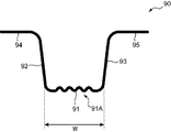
図12に示すように、プレス成形品90は、ハット状に加工された形状を有し、被プレス部31のプレス成形により増厚された天板部91と、天板部91の両端に繋がった縦壁部92,93と、縦壁部92,93の端部(天板部91と繋がる側と反対側の端部)に繋がったフランジ部94,95と、を有する。縦壁部92,93及びフランジ部94,95は、周辺部32,33(図1)に相当する部分であり、天板部91よりも板厚が小さくなっている。つまり、プレス成形品90は、天板部91において部分増厚されたものとなっている。また図12に示すように、天板部91(増厚部)には、第1金型10及び第2金型20のプレス成形面10A,20Aの凹凸面に沿うように連続した凹凸領域91Aが形成されている。この凹凸領域91Aは、天板部91の図12における左右方向における幅Wに対して十分に小さいピッチで繰り返されるように形成された波状の部位である。このように凹凸領域91Aを設けることによって、平坦面状のものに比べて増厚部91における強度がより向上している。
As shown in FIG. 12, the press-formed
[作用効果]
次に、上記本実施形態に係るプレス成形装置1及びプレス成形品の製造方法の特徴及びその作用効果について説明する。
[Effects]
Next, the features of the press-forming
プレス成形装置1は、板状の被プレス部材30に形成された曲がった形状(湾曲形状)の被プレス部31をプレス成形することによりプレス成形品90を製造する装置である。プレス成形装置1は、上側プレス成形面10Aを有する第1金型10と、上側プレス成形面10Aに対向する下側プレス成形面20Aを有し、第1金型10との間において被プレス部31が収容されるプレス空間Sを形成する第2金型20と、プレス空間Sが縮小されるように第1金型10と第2金型20とを相対移動させて互いに近づける駆動部40と、を備えている。第2金型20には、被プレス部31における2つの第1屈曲部31Aを保持するための凹溝状の一対の保持部20Bが互いに離間した状態で設けられている。第1金型10は、2つの保持部20Bの間に位置すると共に第2金型20に向かって突出する形状し、被プレス部31における第2屈曲部31Bをプレスするための押圧部14を有する。
The
上記プレス成形品の製造方法は、板状の被プレス部材30に形成された湾曲形状の被プレス部31をプレス成形することによりプレス成形品90を製造する方法である。この製造方法は、被プレス部材30を第1金型10と第2金型20との間に配置する工程S10と、第1金型10と第2金型20とを相対移動させて互いに近づけることにより、被プレス部31の高さHが小さくなるように被プレス部31をプレス成形する工程S20と、を備えている。プレス成形する工程S20では、被プレス部31において第2金型20に向かって凸状に屈曲する一対の第1屈曲部31Aを、第2金型20において互いに離間するように設けられた凹溝状の一対の保持部20Bにより保持しつつ、被プレス部31において一対の第1屈曲部31Aの間の位置から第1金型10に向かって凸状に屈曲する第2屈曲部31Bを第1金型10の押圧部14によりプレスして変形させることにより被プレス部31を増厚させる。
The method for manufacturing a press-formed product is a method for manufacturing a press-formed
上記特徴によれば、被プレス部31を増厚に必要な線長が確保されるように曲がった形状に構成し、当該被プレス部31の高さHが小さくなるようにプレス成形することにより増厚部を形成することができる。このため、図2に示す比較例のように平板状の被プレス部310にマイクロビード310Aを形成する場合に比べて増厚に必要な線長をより長く確保することが可能となり、増厚量が大きいプレス成形品90を製造することができる。また被プレス部31のプレス成形中において、第1屈曲部31Aを第2金型20の保持部20Bにより保持しつつ、第1屈曲部31Aの間に設けられた第2屈曲部31Bは第1金型10の押圧部14によりプレスされる。これにより、被プレス部31の両側、あるいは、中央部に材料が偏在してしまうことが抑制される。このようにプレス成形中における材料の流動を制御することにより、狙いの増厚量を得ることが可能となり、またプレス成形品90における割れの起点となり得るような局所的な減肉を防ぐことができる。その結果、所望の形状のプレス成形品が適切に得られる。
According to the above feature, by forming the pressed
上記プレス成形品の製造方法において、プレス成形する工程S20では、被プレス部材30における被プレス部31以外の部分(周辺部32,33)よりも板厚が大きくなるように被プレス部31をプレス成形する。これにより、増厚部が部分的に形成されることにより強度が向上したプレス成形品90を製造することができる。
In the above-described method for manufacturing a press-formed product, in the step S20 of press-forming, the pressed
上記プレス成形品の製造方法において、プレス成形する工程S20では、成形後に被プレス部31の高さHがなくなるまで、すなわち、周辺部32,33の被プレス部31に接続される端部と、被プレス部31とが上下方向において略同じ位置になるまで被プレス部31をプレス成形する。これにより、被プレス部31における増厚量をより大きくすることができ、強度がより向上したプレス成形品90を製造することができる。
In the above-described method of manufacturing a press-formed product, in the step S20 of press-forming, until the height H of the pressed
上記プレス成形品の製造方法において、被プレス部材30は、被プレス部31の端部に繋がった周辺部32,33を有する。プレス成形する工程S20では、周辺部32,33の被プレス部31に繋がった部分を第1金型10(第1金型周辺部12)と第2金型20(第2金型周辺部22)とにより挟持する。これにより、プレス成形中において被プレス部31の端部から中央部に向かって材料の流動を促すことが可能となり、被プレス部31の端部において過剰量の材料が偏在することをより効果的に抑制することができる。
In the method of manufacturing a press-formed product, the member to be pressed 30 has the
上記プレス成形品の製造方法では、プレス成形する工程S20において、被プレス部31に第1屈曲部31A及び第2屈曲部31Bを形成する。より具体的には、プレス成形する工程S20は、被プレス部31に第1屈曲部31A及び第2屈曲部31Bを形成する屈曲工程S21と、第1屈曲部31Aを保持部20Bにより保持しつつ、第2屈曲部31Bをプレスして変形させる変形工程S22と、を含む。このように、プレス成形中において第1及び第2屈曲部31A,31Bを被プレス部31に形成することにより、プレス成形前に第1及び第2屈曲部31A,31Bを予め形成する必要がなく、製造プロセスを効率化することができる。
In the above-described method of manufacturing a press-formed product, the first
上記プレス成形品の製造方法において、第1金型10は、押圧部14を有する第1金型中央部11と、第1金型中央部11と別体に形成され、第1金型中央部11と独立して移動可能に構成された第1金型周辺部12と、を有する。プレス成形する工程S20では、第1金型周辺部12を移動させることにより被プレス部31において第1屈曲部31A及び第2屈曲部31Bを形成した後、第2屈曲部31Bを押圧部14によりプレスして変形させる。より具体的には、屈曲工程S21では、第1金型周辺部12を下方に移動させることにより被プレス部31において第1屈曲部31A及び第2屈曲部31Bを形成する。そして、変形工程S22では、第1金型中央部11を下方に移動させることにより第2屈曲部31Bを押圧部14によりプレスして変形させる。これにより、プレス成形中において被プレス部31に第2屈曲部31Bが形成された後に第1金型中央部11の移動を開始させることができ、第2屈曲部31Bを押圧部14によってより確実にプレスすることができる。
In the method for manufacturing a press-formed product, the
上記プレス成形品の製造方法では、プレス成形する工程S20の完了時において、押圧部14と第2金型20との間の距離L1と保持部20Bと第1金型10との間の距離L2が同じになる。これにより、被プレス部31の厚みの均一化を図ることができる。
In the method of manufacturing a press-formed product, at the time of completion of the step S20 of press-forming, the distance L1 between the
上記プレス成形品の製造方法において、プレス成形する工程S20では、被プレス部31に凹凸領域91Aを付与する。これにより、凹凸領域91Aによって補強され、強度がより向上したプレス成形品90を製造することができる。
In the above-described method for manufacturing a press-formed product, in the step S20 of press-forming, the pressed
上記プレス成形品の製造方法では、ホットプレスにより被プレス部材30を成形する。上述の通り、本実施形態ではプレス成形中において被プレス部31における材料の流動を制御することができるため、材料が流動し易いホットプレスの場合でも狙いの増厚量を得ることができる。
In the method of manufacturing a press-formed product, the member to be pressed 30 is formed by hot pressing. As described above, in the present embodiment, since the flow of the material in the pressed
(変形例)
実施形態1では、変形工程S22において、プレスの前後において被プレス部31の板厚を変化させることなく凹凸領域91Aを付与することも可能である。この場合であっても、凹凸領域91Aが付与されることにより、プレス成形品の強度を確保することができる。以下の実施形態においても同様である。なお、凹凸領域91Aにおける凹凸部分の上下方向(図9等参照)の高さ、すなわち、頂部と底部との間の距離は被プレス部31が増厚される場合に比べて高くなる。このように、被プレス部31は、プレス成形により板厚が減少しなければ良く、上記実施形態1のように増厚するようにプレス成形されてもよいし、一定の板厚を保持するようにプレス成形されてもよい。
(Modification)
In the first embodiment, in the deformation step S22, it is also possible to provide the
(実施形態2)
次に、本発明の実施形態2に係るプレス成形装置2及びプレス成形品の製造方法について、図13〜図18を参照して説明する。なお、実施形態2では、上記実施形態1と異なる点についてのみ詳細に説明する。
(Embodiment 2)
Next, a
[プレス成形装置]
図13に示すように、プレス成形装置2は、板状の被プレス部材70に形成された断面視M字状に曲がった形状の被プレス部71をプレス成形することによりプレス成形品を製造する装置である。被プレス部71の線長は、上記実施形態1と同様に、図12に示すプレス成形品90における凹凸領域91Aに沿った長さよりも大きくなっている。プレス成形装置2は、上金型50と、下金型60と、駆動部40と、を有する。実施形態2では、後述するように押圧部61が下金型60に設けられており、下金型60は、図1に示す押圧部14が設けられる第1金型10に対応している。以下、下金型60を「第1金型60」と呼ぶ。保持部50Bは上金型50に設けられており、上金型50は、図1に示す保持部20Bが設けられる第2金型20に対応する。以下、上金型50を「第2金型50」と呼ぶ。駆動部40は、第2金型50を第1金型60に近づくように又は第1金型60から離れるように上下方向に移動させる。つまり、実施形態2では、上記実施形態1と異なり、第1金型60の位置を固定しつつ第2金型50を上下移動させる。
[Press molding equipment]
As illustrated in FIG. 13, the
第2金型50は、波状の上側プレス成形面50Aが形成されたブロック状の第2金型中央部51と、第2金型中央部51の両側面を挟むように配置されたブロック状の第2金型周辺部52と、を有する。第2金型中央部51の上部には駆動部40が配置され、第2金型中央部51は駆動部40によって上下移動するように構成されている。上側プレス成形面50Aは、連続した凹凸領域によって構成されており、中央の凹溝を挟むように互いに離間して設けられた2つの凹溝が保持部50Bとなっている。この保持部50Bによって、被プレス部71に形成された2つの第1屈曲部71Aを保持することができる。本実施形態では、第2金型中央部51が上側成形用金型部に相当し、第2金型周辺部52が上側挟持用金型部に相当する。
The
第1金型60は、上側プレス成形面50Aに対向する波状の下側プレス成形面60Aを有する。被プレス部71は、上側プレス成形面50Aと下側プレス成形面60Aとの間に形成されたプレス空間Sに収容され、周辺部72,73は、第2金型周辺部52と第1金型60との間に配置される。下側プレス成形面60Aは、その中央に第2金型50に向かって突出する形状を有する押圧部61を有しており、この押圧部61によって被プレス部71に形成された第2屈曲部71Bをプレスすることができる。本実施形態では、押圧部61が第1金型60の一部となっており、上記実施形態1と異なり押圧部61が他の金型部分と共に一体として移動する。
The
また本実施形態では、第1金型60の中央部において下側プレス成形面60Aが形成された部分が下側成形用金型部に相当し、その両側の部分が下側挟持用金型部に相当する。つまり、本実施形態では、上記実施形態1と異なり、下側成形用金型部と下側挟持用金型部とが一つの第1金型60として一体形成されている。
In the present embodiment, the portion where the lower
[プレス成形品の製造方法]
次に、上記プレス成形装置2を用いて実施されるプレス成形品の製造方法について説明する。
[Manufacturing method of press-formed product]
Next, a method of manufacturing a press-formed product performed using the press-forming
まず工程S10(図5)では、曲げ加工によって第1屈曲部71A及び第2屈曲部71Bが被プレス部71に予め形成された被プレス部材70が準備され、加熱により軟化状態となった後、図13に示すように第2金型50と第1金型60との間に配置される。このとき、被プレス部71がプレス空間Sに位置すると共に、周辺部72,73が第2金型周辺部52と第1金型60とにより挟持されて固定される。また第1屈曲部71Aが第2金型50の保持部50Bに嵌り込み、且つ第2屈曲部71Bが第1金型60の押圧部61に当接する状態とされる。
First, in step S10 (FIG. 5), the pressed
次に工程S20(図5)では、駆動部40によって第2金型中央部51を第1金型60に向かって下降させることにより、プレス空間Sを縮小させる。これにより、図14〜図18において順に示すように、周辺部72,73が挟持された状態で被プレス部71の高さHが徐々に小さくなり、被プレス部71が増厚される。このとき、上記実施形態1と同様に、第1屈曲部71Aが保持部50Bによって保持されることにより第1屈曲部71Aの外側へ過剰量の材料が流動するのが抑制され、また第2屈曲部71Bが押圧部61によってプレスされることにより第1屈曲部71Aの間に過剰量の材料が偏在するのも抑制される。これにより、図18に示すように、連続した凹凸領域が形成された増厚部を有する平板状のプレス成形品が製造される。
Next, in step S20 (FIG. 5), the press space S is reduced by lowering the second mold
このように実施形態2では、第1屈曲部71A及び第2屈曲部71Bが被プレス部71に予め形成された被プレス部材70が準備され、これをプレス成形することによりプレス成形品が製造される。このように、プレス成形前に第1及び第2屈曲部71A,71Bを被プレス部71に予め形成することにより、第1屈曲部71Aを第2金型50の保持部50Bに対向する位置に、第2屈曲部71Bを第1金型60の押圧部61に対向する位置により確実に形成することができる。その結果、プレス成形中において第1屈曲部71Aを保持部50Bにおいてより確実に保持し、第2屈曲部71Bを押圧部61によってより確実にプレスすることができる。
As described above, in the second embodiment, the pressed
なお、図13に示すように、プレス開始前の状態において押圧部61が第2屈曲部71Bに当接していてもよいがこれに限定されず、プレス開始前の状態において押圧部61と第2屈曲部71Bとの間に隙間が形成されており、プレス中において第2金型中央部51を下降させることにより押圧部61が第2屈曲部71Bに当接してもよい。
In addition, as shown in FIG. 13, the
(実施形態3)
次に、本発明の実施形態3に係るプレス成形装置3及びプレス成形品の製造方法について、図19を参照して説明する。なお、実施形態3では、上記実施形態1と異なる点についてのみ説明する。
(Embodiment 3)
Next, a
図19に示すように、プレス成形装置3において、第1金型15(上金型)は波状の上側プレス成形面15Aを有しており、当該上側プレス成形面15Aは第2金型中央部28(第2金型)に向かって中央が凸状に膨出した形状を有する。また上側プレス成形面15Aの頂部には、上記実施形態1と同様に押圧部15Bが設けられている。また第2金型中央部28は、上側プレス成形面15Aに対向する波状の下側プレス成形面28Aを有し、当該下側プレス成形面28Aは第1金型15から離れるように凹状の形状を有する。上側及び下側プレス成形面15A,28Aには、上記実施形態1と同様に、連続した凹凸領域が形成されている。また下側プレス成形面28Aには、上記実施形態1と同様に、互いに離間するように一対の保持部28Bが設けられている。
As shown in FIG. 19, in the
このプレス成形装置3では、被プレス部31が上側及び下側プレス成形面15A,28Aの間に位置し、周辺部32,33が第1金型15と第2金型周辺部29との間に位置するように被プレス部材30が配置され、第1金型15を下降させることにより被プレス部31がプレス成形される。これにより、被プレス部31は、上側及び下側プレス成形面15A,28Aの形状に沿って、第2金型中央部28に向かって凸状の屈曲形状31Gを有するようにプレス成形される。この屈曲形状31Gとは、図19に示すように第2金型中央部28に向かって突き出るように湾曲した形状である。また凹凸領域91Aは屈曲形状31G上に同時に成形される。このとき、成形後における被プレス部31の高さH1は、成形前の台形状の被プレス部31の高さH(図1)よりも小さくなる。また、屈曲形状31Gの図19の左右方向における幅は、凹凸領域91Aのピッチに比べて大きい。本実施形態では、上述のような形状のプレス成形面15A,28Aが形成された金型を用いることにより、増厚部が屈曲したプレス成形品を製造することができる。なお、本実施形態とは逆に、第1金型15に向かって凸の屈曲形状を有するように被プレス部31がプレス成形されてもよい。
In the
(実施形態4)
次に、本発明の実施形態4に係るプレス成形品の製造方法について、図20のフローチャートを参照して説明する。図20に示すように、実施形態4では、上記実施形態1と同様に被プレス部材30を配置する工程S10及び被プレス部31をプレス成形する工程S20が順に実施された後、被プレス部31の凹凸領域を平坦化する工程S30がさらに実施される。
(Embodiment 4)
Next, a method for manufacturing a press-formed product according to Embodiment 4 of the present invention will be described with reference to the flowchart in FIG. As shown in FIG. 20, in the fourth embodiment, after the step S10 of arranging the member to be pressed 30 and the step S20 of press-forming the part to be pressed 31 are sequentially performed in the same manner as in the first embodiment, the part to be pressed 31 The step S30 of flattening the uneven region is further performed.
具体的には、図21に示すように、連続する凹凸領域31Dが形成された被プレス部31を平坦面状のプレス成形面83A,84Aを有する金型83,84の間に配置し、当該プレス成形面83A,84Aによって被プレス部31を厚み方向にプレスすることにより、凹凸領域31Dを平坦化することができる。これにより、図22に示すように、凹凸領域がなくなり平坦面34Aが形成された増厚部34を有するプレス成形品を製造することができる。このように、被プレス部31において一旦凹凸領域31Dを形成した後、当該凹凸領域31Dを平坦化することにより、被プレス部31を直接平坦形状に成形する場合と異なり、板材の座屈を防ぐことができる。上述の実施形態3においても、実施形態4と同様に、屈曲形状31Gに凹凸領域91Aが形成された後、金型などを用いて凹凸領域91Aを厚み方向にプレスして平坦化する工程がさらに行われてもよい。
Specifically, as shown in FIG. 21, the pressed
(その他実施形態)
最後に、本発明のその他実施形態について説明する。
(Other embodiments)
Finally, other embodiments of the present invention will be described.
図23に示すように、第1金型10の上側プレス成形面10A及び第2金型20の下側プレス成形面20Aにおける凹凸形状は、断面視において左右非対称であってもよい。つまり、面全体において凹溝の幅が一定でなくてもよい。また図24に示すように、被プレス部材30において複数(2つ)の被プレス部31が形成され、これらをプレス成形することにより複数の増厚部が形成されたプレス成形品が製造されてもよい。被プレス部31の数は、3つ以上設けられてもよい。
As shown in FIG. 23, the irregularities on the upper
実施形態1では、プレス成形品に所望の強度が得られる場合には、必ずしも被プレス部が均一に増厚されている必要はない。他の実施形態においても同様である。 In the first embodiment, when a desired strength is obtained in the press-formed product, the pressed portion does not necessarily need to be uniformly thickened. The same applies to other embodiments.
上記実施形態1において、被プレス部31の中央に第2屈曲部31Bが形成される場合に限定されず、中央よりも一方の端部側の位置に形成されてもよい。また被プレス部31において一対の第1屈曲部31A及びその間に位置する1つの第2屈曲部31Bのみが形成される場合に限定されず、複数対の第1屈曲部31A及びその間に位置する第2屈曲部31Bが形成されてもよい。
In the first embodiment, the present invention is not limited to the case where the second
上記実施形態1において、第1金型10のみが移動する場合に限定されず、第2金型20も上側に向かって移動してもよいし、第1金型10及び第2金型20の両方が移動してもよい。第1金型中央部11と第1金型周辺部12とが一体とされてもよい。
In the first embodiment, the present invention is not limited to the case where only the
今回開示された実施形態は、全ての点で例示であって、制限的なものではないと解されるべきである。本発明の範囲は、上記した説明ではなくて特許請求の範囲により示され、特許請求の範囲と均等の意味及び範囲内での全ての変更が含まれることが意図される。 The embodiments disclosed this time are to be considered in all respects as illustrative and not restrictive. The scope of the present invention is defined by the terms of the claims, rather than the description above, and is intended to include any modifications within the scope and meaning equivalent to the terms of the claims.
1,2,3 プレス成形装置
10 上金型(第1金型)
10A 上側プレス成形面(プレス成形面)
14 押圧部
20 下金型(第2金型)
20A 下側プレス成形面(プレス成形面)
20B 保持部
30 被プレス部材
31 被プレス部
31A 第1屈曲部
31B 第2屈曲部
32,33 周辺部
40 駆動部
90 プレス成形品
91 天板部(増厚部)
91A 凹凸領域
P1,P2 接続部
S プレス空間
T1,T2 板厚
1,2,3
10A Upper press forming surface (press forming surface)
14
20A Lower press forming surface (press forming surface)
91A Uneven area P1, P2 Connection S Press space T1, T2 Thickness
Claims (12)
前記被プレス部材を第1金型と第2金型との間に配置する工程を備え、
前記第1金型は、押圧部を含み、
前記第2金型は、少なくとも2つの溝状の保持部が互いに離間するように設けられた成形面を含み、
前記方法は、前記第1金型と前記第2金型とを相対移動させて互いに近づけることにより、前記被プレス部の高さが小さくなるように前記被プレス部をプレス成形する工程をさらに備え、
前記プレス成形する工程では、前記第2金型に形成された前記2つの溝状の保持部に対して前記被プレス部がプレスされるにつれて、前記第2金型に向かって凸状に屈曲する一対の第1屈曲部及び前記一対の第1屈曲部の間の位置から前記第1金型に向かって凸状に屈曲する第2屈曲部が前記被プレス部に形成され、
前記プレス成形する工程では、前記2つの溝状の保持部により前記一対の第1屈曲部を保持しつつ、前記一対の第1屈曲部の間の位置に形成された前記第2屈曲部を前記第1金型の前記押圧部により前記第2金型に向かってプレスして変形させることにより前記第2屈曲部の中央を前記第2金型に向かって屈曲させる、プレス成形品の製造方法。 A method of manufacturing a press-formed product by press-forming a pressed portion having a curved shape formed in a plate-shaped pressed member,
Comprising the step of placing the object to be pressed member between the first mold and the second mold,
The first mold includes a pressing portion,
The second mold includes a molding surface provided with at least two groove-shaped holding portions separated from each other,
The method by approaching each other and said second mold and said first mold are relatively moved, the further the the object to be pressed portion so that the height of the press section is reduced as engineering press forming Prepared,
In the step of press molding, as the pressed portion is pressed against the two groove-shaped holding portions formed in the second mold, the convex portion is bent toward the second mold. A second bent portion that is bent in a convex shape toward the first mold from a position between the pair of first bent portions and the pair of first bent portions is formed in the pressed portion,
The pressing at the molding to process, the two while maintaining the first bent portions of the pair by a groove-like hold portion, said second bent portion formed at a position between the first bent portion before Symbol pair toward the second mold by the pressing portion of the first mold to bend toward the center of the second bent portion in the second mold by deforming and pressing, the press-molded product manufacturing Method.
前記プレス成形する工程では、前記第1金型周辺部を前記第2金型に向かって移動させることにより前記被プレス部において前記第1屈曲部及び前記第2屈曲部を形成した後、前記第2屈曲部を前記押圧部によりプレスして変形させる、請求項1に記載のプレス成形品の製造方法。 The first mold is formed separately from the first mold central portion having the pressing portion and the first mold central portion, and is configured to be movable independently of the first mold central portion. And a first mold peripheral portion,
In the step of press forming, the first bent portion and the second bent portion are formed in the pressed portion by moving the first mold peripheral portion toward the second mold, and then the second bent portion is formed. 2. The method for manufacturing a press-formed product according to claim 1 , wherein the bent portion is pressed and deformed by the pressing portion.
第1プレス成形面を有する第1金型と、
前記第1プレス成形面に対向する第2プレス成形面を有し、前記第1金型との間において前記被プレス部が収容されるプレス空間を形成する第2金型と、を備え、
前記第2プレス成形面には、少なくとも2つの溝状の保持部が互いに離間するように設けられており、
前記プレス成形装置は、前記プレス空間が縮小されるように前記第1金型と前記第2金型とを相対移動させて互いに近づける駆動部をさらに備え、
前記駆動部によって前記第1金型と前記第2金型とを互いに近づけることにより、前記第2金型に向かって凸状に屈曲する一対の第1屈曲部及び前記一対の第1屈曲部の間の位置から前記第1金型に向かって凸状に屈曲する第2屈曲部が前記被プレス部に形成されるように構成されており、
前記第1金型は、前記2つの溝状の保持部の間に位置すると共に前記第2金型に向かって突出する形状を有し、前記被プレス部における前記第2屈曲部をプレスするための押圧部を有する、プレス成形装置。 A press forming apparatus for manufacturing a press-formed product by press-forming a pressed portion having a bent shape formed in a plate-shaped pressed member,
A first mold having a first press forming surface;
A second mold that has a second press-molding surface facing the first press-molding surface and forms a press space in which the pressed part is housed between the first mold and the first mold .
On the second press-formed surface, at least two groove-shaped holding portions are provided so as to be separated from each other,
The press forming apparatus further includes a driving unit that relatively moves the first mold and the second mold so as to approach each other so that the press space is reduced,
By bringing the first mold and the second mold closer to each other by the driving unit, a pair of first bent portions and a pair of the first bent portions bent in a convex shape toward the second mold are formed. A second bent portion bent in a convex shape toward the first mold from a position therebetween is configured to be formed in the pressed portion;
Wherein the first mold, the conjunction is located between two groove-shaped holding portion has a shape protruding toward the second mold, for pressing said second bend of the object press section Press forming device having a pressing portion of
Priority Applications (4)
| Application Number | Priority Date | Filing Date | Title |
|---|---|---|---|
| JP2016015907A JP6659380B2 (en) | 2016-01-29 | 2016-01-29 | Method for manufacturing press-formed product and press-forming apparatus |
| US15/366,989 US10300519B2 (en) | 2016-01-29 | 2016-12-01 | Manufacturing method of press-formed article, press-formed article, and press forming apparatus |
| CN201611248434.9A CN107020335B (en) | 2016-01-29 | 2016-12-29 | The manufacturing method of stamping part, stamping part and press molding equipment |
| EP17000007.9A EP3199256B1 (en) | 2016-01-29 | 2017-01-03 | Manufacturing method of press-formed article and press forming apparatus |
Applications Claiming Priority (1)
| Application Number | Priority Date | Filing Date | Title |
|---|---|---|---|
| JP2016015907A JP6659380B2 (en) | 2016-01-29 | 2016-01-29 | Method for manufacturing press-formed product and press-forming apparatus |
Publications (2)
| Publication Number | Publication Date |
|---|---|
| JP2017131960A JP2017131960A (en) | 2017-08-03 |
| JP6659380B2 true JP6659380B2 (en) | 2020-03-04 |
Family
ID=57868010
Family Applications (1)
| Application Number | Title | Priority Date | Filing Date |
|---|---|---|---|
| JP2016015907A Active JP6659380B2 (en) | 2016-01-29 | 2016-01-29 | Method for manufacturing press-formed product and press-forming apparatus |
Country Status (4)
| Country | Link |
|---|---|
| US (1) | US10300519B2 (en) |
| EP (1) | EP3199256B1 (en) |
| JP (1) | JP6659380B2 (en) |
| CN (1) | CN107020335B (en) |
Families Citing this family (13)
| Publication number | Priority date | Publication date | Assignee | Title |
|---|---|---|---|---|
| EP3485995B1 (en) * | 2016-07-13 | 2022-05-04 | Nippon Steel Corporation | Hot-stamp molded product, automobile member, and method for producing hot-stamp molded product |
| JP6721544B2 (en) | 2017-06-28 | 2020-07-15 | 株式会社神戸製鋼所 | Method for manufacturing press-formed products |
| CN109256884A (en) | 2017-10-13 | 2019-01-22 | 朱卫 | A kind of motor case produced with titanium |
| JP7017944B2 (en) * | 2018-02-09 | 2022-02-09 | 株式会社三井ハイテック | Manufacturing method of metal molded body |
| US20210023601A1 (en) * | 2018-03-28 | 2021-01-28 | Jfe Steel Corporation | Method of designing press-formed product, press-forming die, press-formed product, and method of producing press-formed product |
| CN108817230B (en) * | 2018-07-19 | 2019-12-03 | 安徽江淮汽车集团股份有限公司 | A kind of mould structure |
| JP6677289B1 (en) * | 2018-12-12 | 2020-04-08 | Jfeスチール株式会社 | Press molding method |
| JP7110144B2 (en) * | 2019-03-15 | 2022-08-01 | 本田技研工業株式会社 | Manufacturing method of body frame |
| JP2020146747A (en) * | 2019-03-15 | 2020-09-17 | 本田技研工業株式会社 | Manufacturing method for vehicle body frame and vehicle body frame |
| CN112676416B (en) * | 2019-10-17 | 2023-05-05 | 本田技研工业株式会社 | Method for manufacturing vehicle body skeleton member |
| CN110993128A (en) * | 2019-12-02 | 2020-04-10 | 吉林农业大学 | Grillwork for pressurized water reactor fuel assembly |
| CN111940605B (en) * | 2020-08-04 | 2022-09-23 | 惠州融汇科技有限公司 | New energy automobile battery box top cap shaping structure |
| CN114101474B (en) * | 2020-08-31 | 2024-05-14 | 宝山钢铁股份有限公司 | Two-pass forming processing method for convex hull of module backboard |
Family Cites Families (19)
| Publication number | Priority date | Publication date | Assignee | Title |
|---|---|---|---|---|
| USRE16115E (en) * | 1925-07-14 | Poration | ||
| US1771028A (en) * | 1928-12-31 | 1930-07-22 | Kewanee Boiler Corp | Method of corrugating metal boiler sheets |
| SE463082B (en) * | 1986-10-24 | 1990-10-08 | Nordisk Kartro Ab | DEVICE FOR PROFILING A STEP FORMATED MATERIAL COVER |
| FR2660220B1 (en) * | 1990-04-03 | 1995-02-24 | Lorraine Laminage | PROCESS AND DEVICE FOR FORMING A RELIEF PART ON A SHEET OF SHEET AND PRODUCT OBTAINED ACCORDING TO THIS PROCESS. |
| JPH05154572A (en) * | 1991-12-03 | 1993-06-22 | Matsushita Electric Ind Co Ltd | Forming method and mold for forming |
| JP3950023B2 (en) * | 2002-08-21 | 2007-07-25 | 中央精機株式会社 | Manufacturing method of wheel disc for automobile |
| JP4418168B2 (en) * | 2003-05-14 | 2010-02-17 | 本田技研工業株式会社 | Manufacturing method of elliptical ring |
| JP2009072801A (en) * | 2007-09-19 | 2009-04-09 | Topre Corp | Method and device for partially thickening hot-pressed component |
| JP2011005552A (en) * | 2008-09-01 | 2011-01-13 | Mazda Motor Corp | Method of manufacturing member having closed cross section made of metal |
| JP5515279B2 (en) * | 2008-11-20 | 2014-06-11 | 日産自動車株式会社 | Press-molded product, press-molded product manufacturing method and manufacturing apparatus |
| JP5470812B2 (en) * | 2008-11-20 | 2014-04-16 | 日産自動車株式会社 | Method and apparatus for manufacturing a press-molded product, and press-molded product |
| JP5416498B2 (en) * | 2009-07-23 | 2014-02-12 | 本田技研工業株式会社 | Method and apparatus for forming tailored blank plate |
| JP5585103B2 (en) * | 2010-02-04 | 2014-09-10 | トヨタ自動車株式会社 | Framework member and method of manufacturing the framework member |
| EP3943204A1 (en) * | 2011-05-20 | 2022-01-26 | Nippon Steel Corporation | Press forming method |
| CN105339104B (en) * | 2013-06-25 | 2017-05-03 | 日产自动车株式会社 | Device and method for forming thin-plate substrate |
| JP6073194B2 (en) | 2013-07-03 | 2017-02-01 | 昭和電工株式会社 | Magnetic recording medium, magnetic storage device |
| JP6237313B2 (en) * | 2014-02-17 | 2017-11-29 | トヨタ自動車株式会社 | Thickening method for press parts and press parts for vehicles |
| KR101929643B1 (en) * | 2014-03-28 | 2018-12-14 | 신닛테츠스미킨 카부시키카이샤 | Method for manufacturing sheet-shaped formed component having multiple sections of increased thickness, and sheet-shaped formed component having multiple sections of increased thickness |
| CN204770231U (en) * | 2015-07-18 | 2015-11-18 | 宁波永诚五金机械有限公司 | Expansion sleeve's production mould |
-
2016
- 2016-01-29 JP JP2016015907A patent/JP6659380B2/en active Active
- 2016-12-01 US US15/366,989 patent/US10300519B2/en active Active
- 2016-12-29 CN CN201611248434.9A patent/CN107020335B/en active Active
-
2017
- 2017-01-03 EP EP17000007.9A patent/EP3199256B1/en active Active
Also Published As
| Publication number | Publication date |
|---|---|
| EP3199256A1 (en) | 2017-08-02 |
| CN107020335A (en) | 2017-08-08 |
| CN107020335B (en) | 2019-08-20 |
| EP3199256B1 (en) | 2019-03-13 |
| US20170216901A1 (en) | 2017-08-03 |
| JP2017131960A (en) | 2017-08-03 |
| US10300519B2 (en) | 2019-05-28 |
Similar Documents
| Publication | Publication Date | Title |
|---|---|---|
| JP6659380B2 (en) | Method for manufacturing press-formed product and press-forming apparatus | |
| EP2198986B1 (en) | Press-processing method and press-processing apparatus | |
| JP5835768B2 (en) | Manufacturing method of frame parts | |
| KR102220417B1 (en) | Press-molded product manufacturing method and manufacturing device | |
| JP2017148847A (en) | Press forming die | |
| KR101940165B1 (en) | Press-molding method and method for producing press-molded component | |
| KR101579028B1 (en) | Method for manufacturing closed-structure part and apparatus for the same | |
| JP6721544B2 (en) | Method for manufacturing press-formed products | |
| JP2011067841A (en) | Method of manufacturing hollow pillar-shaped part | |
| JP5866988B2 (en) | Sheet metal bending wrinkle correction device | |
| JP6311853B1 (en) | Hot stamp molded product, manufacturing method and manufacturing apparatus thereof | |
| JP6112226B2 (en) | Press molding method and method of manufacturing press molded parts | |
| JP6550322B2 (en) | Method of manufacturing press-formed product and press forming apparatus | |
| JP3931736B2 (en) | Press mold | |
| JP7341840B2 (en) | Automotive panel manufacturing method | |
| JP7246349B2 (en) | Press molding method and press molding die | |
| JP7350607B2 (en) | Automotive panel manufacturing method | |
| JP7246227B2 (en) | Press molding method and metal plate | |
| JP7272925B2 (en) | Automotive panel manufacturing method | |
| JP2023148085A (en) | Drawing method | |
| JP2021115610A (en) | Method of and device for producing press-molded article | |
| CN115666811A (en) | Press forming die and press forming method |
Legal Events
| Date | Code | Title | Description |
|---|---|---|---|
| A621 | Written request for application examination |
Free format text: JAPANESE INTERMEDIATE CODE: A621 Effective date: 20181203 |
|
| A131 | Notification of reasons for refusal |
Free format text: JAPANESE INTERMEDIATE CODE: A131 Effective date: 20191023 |
|
| A977 | Report on retrieval |
Free format text: JAPANESE INTERMEDIATE CODE: A971007 Effective date: 20191023 |
|
| A521 | Request for written amendment filed |
Free format text: JAPANESE INTERMEDIATE CODE: A523 Effective date: 20191206 |
|
| TRDD | Decision of grant or rejection written | ||
| A01 | Written decision to grant a patent or to grant a registration (utility model) |
Free format text: JAPANESE INTERMEDIATE CODE: A01 Effective date: 20200204 |
|
| A61 | First payment of annual fees (during grant procedure) |
Free format text: JAPANESE INTERMEDIATE CODE: A61 Effective date: 20200206 |
|
| R150 | Certificate of patent or registration of utility model |
Ref document number: 6659380 Country of ref document: JP Free format text: JAPANESE INTERMEDIATE CODE: R150 |