EP3150792B1 - Thermisch getrenntes profilrahmensystem - Google Patents
Thermisch getrenntes profilrahmensystem Download PDFInfo
- Publication number
- EP3150792B1 EP3150792B1 EP16191534.3A EP16191534A EP3150792B1 EP 3150792 B1 EP3150792 B1 EP 3150792B1 EP 16191534 A EP16191534 A EP 16191534A EP 3150792 B1 EP3150792 B1 EP 3150792B1
- Authority
- EP
- European Patent Office
- Prior art keywords
- profile
- frame system
- support element
- section
- plate arrangement
- Prior art date
- Legal status (The legal status is an assumption and is not a legal conclusion. Google has not performed a legal analysis and makes no representation as to the accuracy of the status listed.)
- Active
Links
- 239000011521 glass Substances 0.000 claims description 31
- 239000000463 material Substances 0.000 claims description 14
- 239000002984 plastic foam Substances 0.000 claims description 11
- 238000007789 sealing Methods 0.000 claims description 11
- 239000000853 adhesive Substances 0.000 claims description 9
- 230000001070 adhesive effect Effects 0.000 claims description 9
- 239000002184 metal Substances 0.000 claims description 9
- 229910052751 metal Inorganic materials 0.000 claims description 9
- 239000002131 composite material Substances 0.000 claims description 8
- 230000001788 irregular Effects 0.000 claims description 4
- 229910001092 metal group alloy Inorganic materials 0.000 claims description 3
- 229910000831 Steel Inorganic materials 0.000 claims description 2
- 241000826860 Trapezium Species 0.000 claims description 2
- 229910052782 aluminium Inorganic materials 0.000 claims description 2
- XAGFODPZIPBFFR-UHFFFAOYSA-N aluminium Chemical compound [Al] XAGFODPZIPBFFR-UHFFFAOYSA-N 0.000 claims description 2
- 239000010959 steel Substances 0.000 claims description 2
- 239000004411 aluminium Substances 0.000 claims 1
- 238000005452 bending Methods 0.000 description 14
- 238000011161 development Methods 0.000 description 10
- 230000018109 developmental process Effects 0.000 description 10
- 125000006850 spacer group Chemical group 0.000 description 10
- 239000004033 plastic Substances 0.000 description 8
- 238000009413 insulation Methods 0.000 description 3
- 230000001419 dependent effect Effects 0.000 description 2
- 239000013013 elastic material Substances 0.000 description 2
- 238000010521 absorption reaction Methods 0.000 description 1
- 230000015572 biosynthetic process Effects 0.000 description 1
- 238000010276 construction Methods 0.000 description 1
- 230000000694 effects Effects 0.000 description 1
- 239000006260 foam Substances 0.000 description 1
- 238000009432 framing Methods 0.000 description 1
- 230000005484 gravity Effects 0.000 description 1
- 238000010438 heat treatment Methods 0.000 description 1
- 230000001771 impaired effect Effects 0.000 description 1
- 238000007373 indentation Methods 0.000 description 1
- 239000011810 insulating material Substances 0.000 description 1
- 239000011499 joint compound Substances 0.000 description 1
- 238000004519 manufacturing process Methods 0.000 description 1
- 239000004753 textile Substances 0.000 description 1
- XLYOFNOQVPJJNP-UHFFFAOYSA-N water Substances O XLYOFNOQVPJJNP-UHFFFAOYSA-N 0.000 description 1
Images


Classifications
-
- E—FIXED CONSTRUCTIONS
- E06—DOORS, WINDOWS, SHUTTERS, OR ROLLER BLINDS IN GENERAL; LADDERS
- E06B—FIXED OR MOVABLE CLOSURES FOR OPENINGS IN BUILDINGS, VEHICLES, FENCES OR LIKE ENCLOSURES IN GENERAL, e.g. DOORS, WINDOWS, BLINDS, GATES
- E06B3/00—Window sashes, door leaves, or like elements for closing wall or like openings; Layout of fixed or moving closures, e.g. windows in wall or like openings; Features of rigidly-mounted outer frames relating to the mounting of wing frames
- E06B3/04—Wing frames not characterised by the manner of movement
- E06B3/263—Frames with special provision for insulation
- E06B3/26336—Frames with special provision for insulation with two metal frame members having interpenetrating or overlapping parts when mounted
-
- E—FIXED CONSTRUCTIONS
- E06—DOORS, WINDOWS, SHUTTERS, OR ROLLER BLINDS IN GENERAL; LADDERS
- E06B—FIXED OR MOVABLE CLOSURES FOR OPENINGS IN BUILDINGS, VEHICLES, FENCES OR LIKE ENCLOSURES IN GENERAL, e.g. DOORS, WINDOWS, BLINDS, GATES
- E06B3/00—Window sashes, door leaves, or like elements for closing wall or like openings; Layout of fixed or moving closures, e.g. windows in wall or like openings; Features of rigidly-mounted outer frames relating to the mounting of wing frames
- E06B3/04—Wing frames not characterised by the manner of movement
- E06B3/263—Frames with special provision for insulation
- E06B3/26301—Frames with special provision for insulation with prefabricated insulating strips between two metal section members
- E06B3/26305—Connection details
- E06B2003/26316—Disconnectable connections or permitting shifting between the sections
-
- E—FIXED CONSTRUCTIONS
- E06—DOORS, WINDOWS, SHUTTERS, OR ROLLER BLINDS IN GENERAL; LADDERS
- E06B—FIXED OR MOVABLE CLOSURES FOR OPENINGS IN BUILDINGS, VEHICLES, FENCES OR LIKE ENCLOSURES IN GENERAL, e.g. DOORS, WINDOWS, BLINDS, GATES
- E06B3/00—Window sashes, door leaves, or like elements for closing wall or like openings; Layout of fixed or moving closures, e.g. windows in wall or like openings; Features of rigidly-mounted outer frames relating to the mounting of wing frames
- E06B3/04—Wing frames not characterised by the manner of movement
- E06B3/263—Frames with special provision for insulation
- E06B2003/26349—Details of insulating strips
- E06B2003/2635—Specific form characteristics
- E06B2003/26352—Specific form characteristics hollow
-
- E—FIXED CONSTRUCTIONS
- E06—DOORS, WINDOWS, SHUTTERS, OR ROLLER BLINDS IN GENERAL; LADDERS
- E06B—FIXED OR MOVABLE CLOSURES FOR OPENINGS IN BUILDINGS, VEHICLES, FENCES OR LIKE ENCLOSURES IN GENERAL, e.g. DOORS, WINDOWS, BLINDS, GATES
- E06B3/00—Window sashes, door leaves, or like elements for closing wall or like openings; Layout of fixed or moving closures, e.g. windows in wall or like openings; Features of rigidly-mounted outer frames relating to the mounting of wing frames
- E06B3/04—Wing frames not characterised by the manner of movement
- E06B3/263—Frames with special provision for insulation
- E06B2003/26349—Details of insulating strips
- E06B2003/26387—Performing extra functions
- E06B2003/2639—Provisions for fittings, e.g. locks or hinges
Definitions
- the invention relates to a profile frame system with thermal break, as can be used, for example, in doors, gates, conservatories and windows for holding panels, in particular glass, composite or wooden panels.
- profile frame systems are preferably made of metal or a metal alloy and are exposed to strong temperature fluctuations and different weather conditions, at least on their outside. Additional mechanical loads stem from the fact that doors, gates or windows can be opened or closed.
- a high temperature difference between the outside of the profile frame system, ie that which is arranged outside the building, and the inside of the profile frame system proves to be problematic.
- a high outside temperature could result in faster heating of the building interior.
- the interior of the building would cool down faster in winter.
- profile frame systems are often constructed in two parts. These include a first profile and a second profile.
- the first profile is separated from the second profile by an insulating material.
- Such profile frame systems are known from the prior art. For example, this is on the EP 2 085 557 A2 or the EP 1 327 739 A2 or the EP 2 573 307 A1 or the DE 10 2010 017 586 A1 or the DE 10 2010 023 607 A1 referred.
- the first profile contacts a front surface of the glass panel and the second profile contacts a rear surface of the glass panel.
- An insulating bar connects the two profiles with one another, with the insulating bar being arranged perpendicularly to the front surface or rear surface of the glass pane. Both profiles run parallel to the glass plate.
- a disadvantage of such a structure is that the profile pointing outwards can be lengthened by several millimeters compared to the profile pointing inwards at high outside temperatures. This creates a bending force that presses on the front surface of the glass panel. This and additional mechanical loads, for example due to opening or closing the door or window, can cause the glass plate to shatter.
- a profile frame system which has a first profile and a second profile. Both profiles have a first and a second profile section.
- the first two profile sections run parallel to one another and parallel to a glass plate.
- the two second profile sections run in the direction of the respective other profile and come to rest there in a U-shaped support shoulder and are correspondingly fixed there.
- the two second profile sections also have sections that run parallel to the first profile sections towards one another and end with the formation of a space between them.
- the ends have a concave shape and at least partially encompass a profile bar that is inserted in this space.
- a window and door frame are known. These include a first and a second profile, each having first and second profile sections. First profile sections extend parallel to the glass, whereas second profile sections extend perpendicularly to the glass in the direction of the respective other profile. A profile includes two second profile sections, so that together they form a U-shape. The second profile section of the other profile protrudes into this U-shape. A seal, in particular in the form of textiles, is formed between the respective profile sections. In this case, the second profile sections have a changing cross section, as a result of which the stability of the entire arrangement is increased.
- the DE 26 34 668 A1 shows two profile rails that are connected to one another by means of a connecting piece. Both profile rails have first and second profile sections, which are shown without overlapping when looking at the central plane.
- the metal profile comprises two profile elements, with only a first profile element being indirectly connected to both sides of a glass pane.
- the AT 403 827 B describes a roof window with a corresponding profile structure.
- the profile includes an inclined drainage surface which forms a channel which is arranged inside the profile and has openings for the passage of water.
- corner element for the production of sanitary cells is known. This corner element is used to hold two profiles that are fixed at an angle of 90° to each other.
- the DE 2 103 904 A1 describes a metal window frame made of thin sheet metal profiles.
- the metal window frame also includes two profiles, each with one leg.
- the legs of the two profiles run towards one another and at least partially encompass a profile bar which consists of a plastic.
- U.S. 4,018,022 A and the DE 24 14 720 A1 From the GB 768 499 A a similar structure is known. However, a plastic rod can still be glued to two profile sections.
- the thermal insulation between the outer and the inner profile should not be impaired.
- the profile frame system according to the invention for holding a panel arrangement can be used, for example, in doors, gates, conservatories, windows and the like, in particular for holding panels and panes, eg in the form of glass panes or panels, or in the form of composite or wooden panels.
- It includes a first profile, which has a first profile section and a second profile section.
- the first profile section of the first profile has a contact area which is in direct or indirect contact or can be brought into contact with a first side surface of the panel arrangement.
- a second profile has a first profile section and a second profile section.
- the first profile section of the second profile also has a contact area which is in direct or indirect contact with a second side surface of the panel arrangement or can be brought into contact.
- the second side surface of the plate arrangement runs parallel to the first side surface.
- the second profile section of the first profile and the second profile section of the second profile are in view of an end face of the plate arrangement or in the direction of a center plane arranged overlapping but without contact to form a spacer frame to each other.
- At least one support element is arranged in the spacer frame at least in a partial length area of the profile frame system, as a result of which the second profile section of the first profile and the second profile section of the second profile are connected to one another and/or kept at a distance and/or fastened to one another.
- the support element comprises a first fastening device for fastening to the second profile section of the first profile and a second fastening device for fastening to the second profile section of the second profile.
- the first and second fastening means consist of or comprise an adhesive connection, whereby the support element is connected to the second profile section of the first and second profile, the support element itself consisting of or comprising plastic foam material.
- the first and the second fastening device are designed as form-fitting fastening devices and/or consist of or comprise an adhesive connection, whereby the support element is connected to the second profile section of the first and second profile.
- the support element comprises or consists of plastic, in particular in the form of a continuously cast part or an extruded part.
- a profile frame corner connector is shown, via which two profile frame systems are preferably not transverse and generally perpendicular to the panel plane, but preferably at an angle rotated by 90° with one another connected in such a way that the mechanical stress on the first side surface and/or the second side surface of the panel arrangement is minimized and these forces are now applied to the end face of the panel arrangement, at least not transversely or perpendicularly to the panel arrangement.
- the first profile does not introduce the bending forces that occur transversely or perpendicularly to the panel arrangement, but in the direction of a central plane that runs through the panel arrangement.
- a glass plate in particular is significantly more robust in terms of resistance to the absorption of forces if these forces are applied to the end face or parallel to the center plane and do not act transversely or perpendicularly to the side surface. This means that a glass plate held in this way is significantly more resistant to additional mechanical loads, such as those occur when the door or window is closed, making them less likely to shatter or not shattering at all.
- Composite panels can be deflected by forces acting transversely or perpendicularly to the side surface.
- the wording that the contact area of the second profile section of the first profile is “directly” or “indirectly” in contact or can be brought into contact with the end face of the plate arrangement is to be understood in such a way that in the event of direct contact the contact area of the second profile section is the end face touches the plate arrangement, whereas in the case of an "indirect” contact there is another element, which is preferably inelastic, between the contact area of the second profile section of the profile and the end face of the plate arrangement.
- the further element can be air or, for example, a block.
- the contact area of the first profile section of the first and/or second profile is "indirectly" in contact with the first and/or second side surface of the panel arrangement is to be understood as meaning that an additional element, such as a joint compound, is in between can be arranged, which would not be the case with "direct” contact.
- the profile frame system is predominantly installed in a building in such a way that the first profile is exposed to higher temperature fluctuations and/or higher maximum or lower minimum temperatures than the second profile. This means that the first profile preferably forms part of the outside of the building, whereas the second profile protrudes into the interior of the building.
- a profile frame corner connector is used to connect two profile frame systems running towards one another, for example at a 90° angle, which means that a horizontal profile can be connected to a vertical profile in the corner area, for example.
- the profile frame corner connector comprises a connecting device that is firmly connected to a first profile frame system and extends it in the longitudinal direction and/or protrudes from it. With this connecting device, the second profile section of the first profile of the second profile frame system is firmly connected via at least one screw connection.
- the wording "approximately" is to be understood in such a way that the angle can include 90°+2° or less.
- the second profile section of the first profile also has a contact area which is in direct or indirect contact or can be brought into contact with an end face of the panel arrangement.
- the second profile section of the second profile is arranged further away from the end face of the plate arrangement than the second profile section of the first profile.
- the panel arrangement comprises one panel or multiple panels, the multiple panels lying directly on top of one another and/or being glued to one another.
- the panel arrangement consists of at least two panels arranged parallel to one another and spaced apart from one another.
- the first panel and the second panel each include an inner and an outer side, the inner sides of the first and second panel facing each other and with the outer sides of the first and second panels facing away from each other.
- the first profile portion of the first profile abuts the inside of the first plate and the first profile portion of the second profile abuts the inside or the outside of the second plate.
- the first and/or the second profile and/or at least one spacer are arranged entirely or partially between the two plates.
- the second profile section of the first profile has a contact area that is in direct or indirect contact or can be brought into contact with an end face of the second plate.
- the first side surface of the panel is formed by a front side surface of the panel and the second side surface of the panel is formed by a rear side surface of the panel.
- the panel has a groove-shaped recess on its end face, in which the profile frame system at least partially engages or can be inserted, with two further lateral surfaces running parallel to one another being formed by the groove-shaped recess and with the first lateral surface of the panel being the first lateral surface and wherein the second side surface of the plate forms the second side surface.
- the support element which is designed as a plastic foam material, is arranged in the entire cavity between the first and second profile or only in the spacing space.
- the plastic foam material is preferably softer and therefore more elastic than standard construction foam.
- the support element not according to the invention in the form of plastic, in particular in the form of a continuously cast part or extruded part, is designed in one piece in cross section.
- the support element can also be designed in one piece over the entire length of the profile frame system in the longitudinal direction of the profile frame system. It is also possible for several support elements to be used over the entire length of the profile frame system, with the distance between the individual support elements being selectable.
- This can be less than 50 cm, less than 40 cm, less than 30 cm, less than 20 cm, less than 10 cm or less than 5 cm.
- the individual support elements can also be directly adjacent to one another in such a way that they touch.
- a single support element can have a length that corresponds to the length of the profile frame system. However, the support element can also have a shorter length. In particular, it can be less than 2 m, less than 1.5 m, less than 1 m, less than 80 cm, less than 60 cm, less than 40 cm, less than 30 cm long.
- the first and/or second fastening device of the support element has two mutual flanges or webs which project away from or towards one another and which are attached to two groove-shaped depressions running towards or away from one another on the second profile section of the first and/or second profile are inserted or latched.
- the support element can be integrated very easily into the profile frame system when it is assembled. In doing so advantage is taken of the fact that the two second profile sections run approximately parallel, in any case transversely, to the first profile sections and overlap when looking at the end face of the panel arrangement.
- the first and the second fastening device can be constructed differently. It is thus possible for the first or second fastening device to comprise two feet which preferably move towards one another at an angle, with the flanges or webs projecting towards or away from one another being formed at a first end of each of the two feet.
- the second or the first fastening device i.e. the one on which no feet are formed, comprises a base body on which the flanges or webs which point towards or away from one another are also formed, the two feet being connected to the base body at their second end .
- a first and second fastening device constructed in this way can be pushed into the corresponding grooves on the first or second profile together with the flanges formed on the base body.
- the flanges that are formed on the first ends of the two feet can be designed in such a way that these feet can also be pushed into the grooves.
- the feet are preferably prestressed and want to move further away from each other, so that that fastening device which has the feet can additionally or alternatively be clipped or snapped into the corresponding grooves.
- both the first and the second fastening device each comprise two feet which each move towards one another at an angle.
- the flanges or webs projecting towards and/or away from one another are formed at a first end of all the feet.
- the support member includes a central body connected to the second end of each leg. The feet are preferably of the same length both in the first and in the second exemplary embodiment.
- the feet of the first and/or second fastening device can also be connected to one another at their first end via a web or a plate.
- This web or this plate can protrude in both directions, whereby the two flanges are formed.
- this has a locking receiving space which is arranged between the two feet next to the base body and serves to receive a bolt of a locking device so that the door or gate or window cannot be opened.
- this locking receiving space can also be arranged within the central body, in which case it serves to receive a bolt of a locking device so that the door or gate or window cannot be opened.
- the locking device is not attached to the profile frame system.
- the latch receiving space preferably does not extend through the whole profile frame system, but only through a part of the profile frame system.
- the locking receiving space is arranged between two feet of the support element or in the central body of the support element, there is effective burglary protection because the entire support element and thus the entire profile frame system would have to be dismantled in order to access the bolt of the locking device or .to uncover it.
- the second profile section of the first profile or the second profile section of the second profile comprises a receiving area which, in cross-section when viewed from above, has the shape of a square or a rectangle or a trapezoid or an oval or a circle or a regular or irregular n- Polygon equals or approximates.
- This receiving area serves to create a locking receiving space, which is used to receive a bolt of a locking device so that the door or gate or window cannot be opened.
- the first profile and the second profile are preferably each formed in one piece in cross section.
- the two second profile sections are arranged entirely or at least partially parallel to one another.
- the two second profile sections run transversely to the center plane of the panel arrangement and thus transversely to the first and second side surface of the panel arrangement. They enclose an angle to the center plane which is preferably greater than 30°, preferably greater than 40°, more preferably greater than 50°, more preferably greater than 60°, more preferably greater than 70°, more preferably greater than 80°. This angle preferably corresponds to exactly 90°.
- the supporting element has poorer thermal conductivity than the first and second profiles.
- the support element is designed to be at least partially elastic.
- the width of the second profile section of the first and the second profile section of the second profile overlaps transversely to the longitudinal direction of the profiles to an extent that is greater than 50%, preferably greater than 60%, more preferably greater than 70%, more preferably is greater than 80%, more preferably greater than 90% but preferably less than 98% of the width of the face and/or the thickness of the panel assembly. This ensures that the bending forces are predominantly passed on to the end face or at least to the plate arrangement parallel to the center plane.
- the first profile consists of several pieces along the profile frame system, which are separated from each other in the transverse direction transverse to the longitudinal direction thereof. This means that the maximum bending forces are lower because the magnitude of the bending forces is proportional to the length of the first profile. Consists the first profile consists of a plurality of profile pieces which are separated from one another in the transverse direction transversely to their longitudinal direction, then each of these profile pieces exerts a force on the end face of the panel arrangement which is lower in height than the force which the first profile would exert if it were in Longitudinally would run continuously.
- the second profile section of the first profile or the second profile section of the second profile extends from the respective first profile section in the direction of the opposite first profile section of the second profile or first profile, a distance of less than 30% being formed from this, preferably is less than 25%, more preferably less than 20%, more preferably less than 15%, more preferably less than 10%, but preferably greater than 2% of the width of the face and/or thickness of the panel assembly. This ensures that the bending forces are predominantly introduced into the end face of the plate arrangement or at least parallel to the center plane into the plate arrangement and that the heat transfer resistance between the first and second profile is high.
- the course of the first profile section of the second profile is at least partially adapted to the course of the first profile section of the first profile, as a result of which the distance between the two profile sections is approximately constant.
- At least part of a course of the second profile section of the first and/or second profile is symmetrical to the center plane passing through the panel arrangement.
- Both profiles are preferably made of metal or a metal alloy, preferably aluminum or steel.
- the first profile is designed in one piece with its first and second profile section in the transverse direction and optionally in the longitudinal direction.
- the second profile is also formed in one piece with its first and second profile section in the transverse direction and preferably also in the longitudinal direction.
- this comprises a sealing device which rests against the second profile section of the second profile in a non-positive and/or positive manner and seals the interior of the profile frame system from the outside.
- the sealing device preferably consists of an elastic material, in particular rubber.
- FIG 1A shows a spatial representation of a door frame with the thermally separated profile frame system 1 according to the invention.
- the profile frame system 1 is attached to the edge of a panel arrangement 2, in particular a glass, composite or wooden panel 2 attached.
- a plate arrangement 2 is shown in the form of exactly one glass plate 2, which has a first side surface 3 in the form of a front surface 3a and an opposite second side surface 3' in the form of a rear surface 3'a.
- the front surface 3a preferably points to the outside, so that this side is particularly exposed to the effects of the weather and temperature fluctuations.
- the profile frame system 1 is preferably attached to all four sides of the border of the panel arrangement 2 .
- the panel arrangement 2 can also have several glass panels 2 which are arranged directly one above the other.
- the glass plates 2 can also be glued to one another.
- Figure 1B shows a three-dimensional representation, for example of a glass pane or composite or wooden panel 2, which illustrates the course of a central plane 4, which in this case is a central plane of symmetry 4.
- the central plane 4 runs through the glass or wooden plate 2 and is arranged parallel to the first and second side surfaces 3, 3', ie parallel to the front surface 3a or the rear surface 3'a.
- a glass or wooden plate 2 is often spoken of, although all shapes and configurations of plates and panes are meant without any restrictions, which generally have poor thermal conductivity.
- the panel arrangement 2 also has an end face 5 which, as explained in detail later, is important for the attachment of the profile frame system 1.
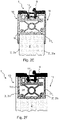
- Figure 2A shows a cross section through the profile frame system 1 according to the invention with two separate profiles 10, 11, which are connected to one another via a support element 12.
- the first profile 10 comprises a first profile section 10 1 and a second profile section 10 2 .
- the first profile section 10 1 of the first profile has a contact area 6 which is in direct or indirect contact with the first side surface 3, ie the front side surface 3a of the panel arrangement 2, or can be brought into contact. It is possible that the end of the first profile section 10 1 of the first profile 10 becomes narrower in diameter.
- the first profile section 10 1 of the first profile 10 is preferably aligned parallel to the center plane 4 , ie the center plane of symmetry 4 .
- the second profile section 10 2 of the first profile 10 is preferably aligned perpendicular to the first profile section 10 1 .
- the second profile 11 also comprises a first profile section 11 1 and a second profile section 11 2 .
- the first profile section 111 of the second profile 11 in turn has a contact area 7 which is in direct or indirect contact with the second side surface 3', ie the rear surface 3'a of the plate arrangement 2, or can be brought into contact with it.
- the rear surface 3'a of the plate assembly 2 is arranged parallel to the front surface 3a and in Figure 2E to recognize.
- the second profile section 10 2 of the first profile 10 has a contact area 8, which directly or indirectly is in contact or can be brought into contact with the end face 5 of the plate arrangement 2 .
- the contact area 8 has a plurality of bearing surfaces 60 which rise in the direction of the end face 5 of the panel arrangement 2 . Consequently, in this exemplary embodiment, the plate arrangement 2 does not rest on the entire surface of the second profile section 10 2 of the first profile 10 .
- the second profile section 11 2 of the second profile 11 is arranged further away from the end face 5 or from a center of the panel arrangement 2 than the second profile section 10 2 of the first profile 10 .
- the center can be the center of the panel arrangement 2 .
- the center can coincide with the center of gravity. It is particularly important that the second profile section 10 2 of the first profile 10 and the second profile section 11 2 of the second profile 11 overlap when looking in the direction of the central plane 4 or when looking at the end face 5 of the panel arrangement 2, but without contact, forming a Spacer 35 are arranged to each other.
- At least one supporting element 12 is arranged within this spacing space 35 .
- This at least one support element 12 can extend over the entire length of the profile frame system 1 or only over at least a partial length.
- This support element 12 connects the second profile section 10 2 of the first profile 10 and the second profile section 11 2 of the second profile 11 to one another and/or keeps them at a distance and/or fastens them to one another.
- the support element 12 consists of plastic, in particular in the form of a continuously cast part.
- the spacing space 35 is not completely filled by the support element 12 . It would therefore be possible for the support element 12 to be supplemented by adhesive material or plastic foam material, so that the spacing space 35 is predominantly or completely filled.
- the contact area 6 of the first profile section 10 1 of the first profile 10 and the contact area 7 of the first profile section 11 1 of the second profile 11 preferably extend over a length along the first profile section 10 1 , 11 1 of the first and/or second profile 10, 11 , which is less than half the length of the first profile section 10 1 , 11 1 of the first and / or second profile 10, 11.
- the contact areas 6, 7 of the first profile section 10 1 , 11 1 of the first and/or second profile 10 , 11 can also extend over the entire length of the first profile sections 10 1 , 11 1 .
- the support element 12 is formed in particular in the form of a continuously cast part made of plastic and is preferably constructed in one piece in cross section. The same applies to the first profile 10 and the second profile 11.
- the two first and second profile sections 10 1 , 10 2 ; 11 1 , 11 2 are each preferably formed in one piece in cross section.
- the supporting element 12 comprises a first fastening device 13 and a second fastening device 14.
- the first fastening device 13 serves to fasten the supporting element 12 to the second profile section 10 2 of the first profile 10.
- the second fastening device 14 of the supporting element 12 serves to fasten to the second profile section 11 2 of the second profile 11.
- the first and/or second fastening device 13, 14 is designed as a positive and/or non-positive fastening device 13, 14.
- first and/or second fastening device 13, 14 is preferably formed from a clip connection or a sliding or plug-in connection or includes one. It would also be possible for the first and/or second fastening device 13, 14 to consist of an adhesive connection and/or a rivet or screw connection or to include such a connection. As a result, the first and/or second fastening device 13, 14 is connected to the second profile section 10 2 , 11 2 of the first and/or profile 10, 11.
- the first and second fastening devices 13, 14 of the support element 12 each comprise two mutually projecting flanges or webs 17 which are attached to two groove-shaped depressions 26, 27 running towards one another on the second profile section 10 2 , 11 2 of the first and second profile 10, 11 can be inserted or locked. It would also be possible for the flanges or webs 17 not to be separated from each other away, but towards each other. In this case, the groove-shaped indentations 26, 27 on the second profile section 10 2 , 11 2 of the first and/or second profile 10, 11 would run away from one another.
- both the first and the second fastening device 13, 14 each have two feet 18, 19 which move towards one another at an angle. At each first end of all feet 18, 19, the flanges or webs 17 projecting away from one another are formed. Furthermore, the support element 12 comprises a central body 15 which is connected to the second end of all the feet 18,19.
- the feet 19 of the second fastening device 14 are additionally connected to one another at their first end via a plate-shaped web 16 .
- All feet 18, 19 preferably also extend in the longitudinal direction of the profile frame system 1.
- the feet 18, 19 preferably extend over the same length as the support element 12 in the longitudinal direction through the profile frame system 1. It would also be possible for interruptions to be formed in the longitudinal direction, so that the feet 18, 19 do not extend continuously over the entire length of the support element 12.
- the central body 15 has the shape of a circle in plan view in cross section. However, it could also correspond to the shape of a square, a rectangle, an oval, a trapezium or a regular or irregular n-polygon or to be close to this.
- a lock receiving space 25 for receiving a bolt 36 of a locking device to prevent the door or gate or window from being opened.
- This locking receiving space 25 therefore preferably does not extend over the entire length of the profile frame system 1, but is only arranged in the immediate vicinity of the locking device. This is mainly the case at the corners of the panel assembly 2 .
- the two second profile sections 10 2 , 11 2 run almost completely parallel to one another.
- the distance between the second profile section 10 2 of the first profile 10 and the first profile section 11 1 of the second profile 11 is approximately the same as the distance between the second profile section 11 2 of the second profile 11 and the first profile section 10 1 of the first profile 10.
- the Wording "roughly" can include a deviation of preferably less than 5%, more preferably less than 3%, more preferably less than 1%.
- the support element 12 is designed and/or built in symmetrically to the center plane 4 , ie to the center plane of symmetry 4 .
- the second profile section 10 2 of the first profile 10 and the second profile section 11 2 of the second profile 11 are also formed symmetrically or predominantly symmetrically to the center plane 4 .
- the second profile section 10 2 of the first profile 10 is connected to the first profile section 10 1 of the first profile 10 at precisely one point. The same also applies here to the second profile section 11 2 in connection with the first profile section 11 1 of the second profile 11.
- the two profile sections 10 2 , 11 2 of the first and second profile 10 , 11 which preferably run parallel or at least partially or partially parallel to one another, overlap (when viewed perpendicularly) in width transverse to the longitudinal direction of the profiles 10 , 11 in one Level greater than 50%, preferably is greater than 60%, more preferably greater than 70%, more preferably greater than 80%, more preferably greater than 90% of the width of the end face 5 and/or the thickness of the panel arrangement 2.
- the two first profile sections 10 1 , 11 1 are preferably of the same thickness. The same preferably also applies to the two second profile sections 10 2 , 11 2 . It is also possible that the individual profile sections 10 1 , 10 2 ; 11 1 , 11 2 have different thicknesses. Preferably, however, all profile sections 10 1 , 10 2 ; 11 1 , 11 2 about the same thickness.
- the profile frame system 1 also includes a sealing device 9 which rests against the second profile section 11 2 of the second profile 11 in a non-positive and/or positive manner and seals the interior of the profile frame system 1 from the outside.
- the sealing device 9 is preferably attached to the second profile section 11 2 of the second profile 11 by means of a positive and/or non-positive attachment.
- the second profile section 112 of the second profile 11 can have additional grooves, preferably running towards one another, into which flanges formed on the sealing device 9 and corresponding to the grooves engage.
- the sealing device 9 is preferably elastic, in particular made of rubber.
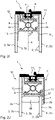
- Figure 2B shows another cross section through the profile frame system 1 with two separate profiles 10, 11, which are connected to one another via a support element 12.
- the support element 12 in turn comprises a first and a second fastening device 13, 14.
- the first fastening device 13 comprises two feet 18 which preferably move towards one another at an angle.
- the flanges or webs 17 protruding away from one another are formed at a respective first end of both feet 18 .
- the second fastening device 14 of the support element 12 comprises a base body 20 on which the flanges or webs 17 projecting away from one another are formed.
- the two feet 18 are connected to this base body 20 at their second end.
- first fastening device 13 may include the base body 20
- second fastening device 14 has the feet 18 .
- two base bodies 20 would also be conceivable, which are connected to one another with two or more feet 18 .
- the profile frame system 1 also has a locking receiving space 25 in this exemplary embodiment, which is arranged between the two feet 18 next to the base body 20 and serves to receive a bolt 36 of the locking device, as a result of which the door or gate or window cannot be opened.
- the lock receiving space 25 is formed in a separate housing 22 .
- This separate housing 22 is then located between the two feet 18 and the base body 20.
- the separate housing 22 can be connected to the second profile section 102 of the first profile 10, for example by means of an adhesive connection.
- the housing 22 is preferably spaced both from the feet 18 and from the base body 20 .
- the second profile section 10 2 of the first profile 10 has at least one, preferably several, additional bearing surfaces 61 which rise in the direction of the spacing space 35 .
- the housing 22 is arranged on this additional bearing surface 61 .
- the feet 18 are preferably at least partially elastic. This preferably applies to all feet 18, 19.
- the two second profile sections 10 2 , 11 2 of the two profiles 10 , 11 run at least partially parallel to one another.
- the distance between the second profile section 10 2 of the first profile 10 and the first profile section 11 1 of the second profile 11 is smaller than the distance between the second profile section 11 2 of the second profile 11 and the first profile section 10 1 of the first profile 10.
- the distance from the housing 22 to the feet 18 and preferably to the base body 20 is the same and more preferably constant.
- Figure 2C shows a cross section through the profile frame system 1 according to the invention with two separate profiles 10, 11 which are connected to one another via a support element 12.
- the support element 12 is in this exemplary embodiment, it is one which consists of or comprises plastic foam material. In this exemplary embodiment, the entire space between the first and the second profile 10, 11 is filled with the supporting element 12. It would also be possible for the support element 12 , in particular if it is a plastic foam material, to be formed only in the spacing space 35 .
- the second profile section 10 2 of the first profile 10 comprises at least one receiving area in cross section, which corresponds to a trapezoid in plan view.
- a housing 22 is introduced within this receiving area, which has a locking receiving space 25, which serves to receive a bolt 36 of a locking device, so that the door or the gate or the window cannot be opened.
- the housing 22, which contains the locking receiving space 25, is predominantly in a form-fitting manner within the receiving area on the second profile section 102 of the first profile 10. It would also be possible for the receiving area to be formed on the second profile section 11 2 of the second profile 11 .
- the receiving area can also have the shape of a square, a rectangle, an oval, a circle or a regular or irregular n-polygon in cross section and in plan view or can be approximated to such.
- the course of the second profile section 11 2 of the second profile 11 is also at least partially adapted to the course of the second profile section 10 2 of the first profile 10 .
- the second profile section 11 2 of the second profile 11 therefore not only has a section that moves in the direction of the first profile section 10 1 of the first profile 10 , but also moves in the direction of the end face 5 of the panel arrangement 2 .
- the second profile section 10 2 of the first profile 10 extends from the first profile section 10 1 of the first profile 10 in the direction of the first profile section 11 1 of the second profile 11. It ends at a distance in front of the first profile section 11 1 of the second profile 11, where this distance is less than 30%, preferably less than 25%, more preferably less than 20%, more preferably less than 15%, more preferably less than 10%, but preferably more than 2% of the width of the face 5 and/or the thickness of the plate arrangement 2.
- the same can also apply to the second profile section 11 2 of the second profile 11, which runs in the direction of the first profile section 10 1 of the first profile 10.
- the trapezoidal receiving area is preferably located approximately in the middle of the second profile section 10 2 of the first profile 10.
- Figure 2D shows a cross section through the profile frame system 1 with two separate profiles 10, 11, which are connected to one another via a support element 12.
- the second profile section 10 2 of the first profile 10 consists of at least a first and a second segment 30 1 , 30 2 , both segments 30 1 , 30 2 having their first end originating at different locations on the first profile section 10 1 on the first profile 10 and extending towards the first profile section 11 2 of the second profile 11, being connected to one another at their second end and wherein the first segment 30 1 is arranged closer to the end face 5 of the plate arrangement 2 or closer to a center of the plate arrangement 2 than the second segment 30 2 and wherein the first segment 30 1 runs approximately parallel to the end face 5 of the plate arrangement 2, so that the second segment 30 2 runs obliquely to the end face 5 of the plate 2 .
- the situation is similar for the second profile section 11 2 of the second profile 11 .
- This also consists of at least a first and a second segment 31 1 , 31 2 .
- Both segments 31 1 , 31 2 originate with their first end at different points on the first profile section 11 1 of the second profile 11 and extend in the direction of the first profile section 10 1 of the first profile 10.
- the first segment 31 1 has its second end with connected to the second segment 31 2 .
- the second segment 31 2 has a smaller minimum distance to the end face 5 or to the center of the panel arrangement 2 than the first segment 31 1 .
- the second segment 31 2 is arranged approximately parallel to the second segment 30 2 of the second profile section 10 2 of the first profile 10 over most of its length, with the space 35 for receiving the support element 12 being formed between the two segments 30 2 , 31 2 .
- the support element 12 is generally designed symmetrically to the center plane 4 and/or installed.
- the second profile section 10 2 of the first profile 10 and the second profile section 11 2 of the second profile 11 are designed symmetrically or predominantly symmetrically to the center plane 4 .
- This means that the two second profile sections 10 2 , 11 2 run transversely to the center plane 4 of the panel arrangement 2 and thus transversely to the first and second side surfaces 3, 3 ′, i.e. transversely to the front and rear side surfaces 3a, 3′a of the panel arrangement 2 .
- Bending forces act mainly along the center plane 4 on the support element 12 and thus on the end face 5 or the side faces 3, 3' of the plate arrangement 2.
- the two second profile sections 10 2 , 11 2 or their segments 30 2 , 31 2 and thus the orientation and the effective surfaces of the support element 12 to be wholly or partially at an angle ⁇ to the center plane 4 of the plate arrangement 2 and thus at an angle ⁇ to the first and second side surface 3, 3' and thus to the front and rear side surface 3a, 3'a of the panel arrangement 2, which is greater than 30°, preferably greater than 40°, more preferably greater than 50°, more preferably greater than 60°, more preferably greater than 70°, more preferably greater than 80° and less than 90°.
- the angle ⁇ preferably corresponds to 90°, so that the two second profile sections 10 2 , 11 2 or their segments 30 2 , 31 2 are then perpendicular to the central plane 4 of the plate arrangement 2 and thus perpendicular to the first and second side surfaces 3, 3 ′, in this case perpendicular to the front and rear faces 3a, 3'a of the plate assembly 2.
- Figure 2F shows a cross section through the profile frame system 1 with two separate profiles 10, 11, which are connected to one another via a support element 12, the profile frame system 1 being at least partially inserted into a groove-shaped recess 28 of the panel arrangement 2.
- the groove-shaped recess 28 penetrates the panel arrangement 2 along the entire area to which the profile frame system 1 is to be attached.
- the profile frame system 1 is usually, with the exception of the sealing device 9, almost completely immersed in the groove-shaped recess 28 a. Deviating from this, the profile frame system 1 can also completely immerse into the groove-shaped recess 28 with the sealing device 9 .
- the groove-shaped recess 28 forms two further lateral surfaces 3b, 3'b running parallel to one another, the first lateral surface 3 of the plate arrangement 2 being the first lateral surface 3b in this exemplary embodiment and the second lateral surface 3' of the plate arrangement 2 being the second lateral surface 3'b forms.
- the side of the first profile section 10 1 of the first profile 10 which does not point in the direction of the first profile section 11 1 of the second profile 11 rests against the first lateral surface 3 b of the panel arrangement 2 .
- the same also applies to the second profile 11.
- the side of the first profile section 11 1 of the second profile 11 which does not point in the direction of the first profile section 10 1 of the first profile 10 rests against the second lateral surface 3'b of the plate arrangement 2.
- the first profile section 10 1 of the first profile 10 ends, just like the second profile section 10 2 of the first profile 10, at the end face 5 of the plate arrangement 2.
- the first profile section 11 1 of the second profile 11 also ends, just like the second profile section 10 2 of the first profile 10 on the end face 5 of the panel arrangement 2.
- the plate arrangement 2 is designed in one piece. However, it can also be designed in two parts or generally in several parts.
- the groove-shaped recess 28 by a Plate may be formed, which has small dimensions relative to two other plates between which it is placed.
- the sealing device 9 not only covers the two first profile sections 10 1 , 11 1 , but also the part of the end face 5 of the panel arrangement 2 which protrudes from the other part already covered by the second profile section 10 2 of the first profile 10 .
- the exemplary embodiment Figure 2E can be combined with the other exemplary embodiments, which relate in particular to the support element 12 .
- Figures 2G and 2H show a cross section through the profile frame system 1 with two separate profiles 10, 11, which are connected to one another via a support element 12, the plate arrangement 2 being spaced from the second profile section 102 of the first profile 10. Between the end face 5 of the plate arrangement 2 and the second profile section 10 2 of the first profile 10 is in Figure 2G a cavity is formed which is filled with air. Within Figure 2H is a block 37, which is preferably inelastic, between the end face 5 of the plate arrangement 2 and the second profile section 10 2 of the first profile 10 is arranged.
- Figure 2I shows a cross section through the profile frame system 1 with two separate profiles 10, 11, which are connected to one another via a support element 12, the panel arrangement 2 consisting of two separate panels 2a, 2b, preferably arranged parallel to one another, between which the profile frame system 1 is arranged.
- the first panel 2a and the second panel 2b each comprise an inner side 3b, 3'b and an outer side 3a, 3'a, the inner sides 3b, 3'b of the first and second panels 2a, 2b facing each other and the outer sides 3a, 3'a of the first and second plates 2a, 2b point away from each other.
- the first profile section 10 1 of the first profile 10 bears against the inside 3b of the first plate 2a and the first profile section 11 1 of the second profile 11 bears against the inside 3'b of the second plate 2b.
- the profile frame system 1 comprises Figure 2J a spacer 38.
- the spacer 38 is arranged entirely or partially between the two plates 2a, 2b. It can be made of an elastic or non-elastic material. It preferably touches both the block 37 and the two first profile sections 10 1 , 11 1 .
- figure 3 shows a cross section in a spatial representation through the profile frame system 1 with two separate profiles 10, 11, which are connected to one another by a support element 12.
- the individual elements are shown offset from one another in different ways, which clearly shows how the support element 12 engages with the two second profile sections 10 2 , 11 2 of the two profiles 10 , 11 .
- the support member 12 is the support member 12, which in the Figure 2A explained, to which reference is hereby made.
- the support element 12 can be pushed into the corresponding grooves 27 of the second profile section 10 2 of the first profile 10 .
- the second profile 11 can be pushed over its profile section 11 2 and its grooves 26 over the second fastening device 14 of the support element 12 .
- the sealing device 9 is pushed into the second profile section 11 2 of the second profile 11 via a corresponding receiving device, preferably in the form of grooves running towards one another. Due to the fact that the support element 12 is in contact with the two second profile sections 10 2 , 11 2 over a greater length, the profile frame system 1 is stable and mechanically resilient.
- figure 4 shows a spatial representation of a profile frame corner connector 40, through which two profile frame systems 11 , 12 can be connected to one another at an angle of approximately 90°.
- the aim of the profile frame corner connector 40 is that the thermal insulation of the first profile 10 from the second profile 11 is maintained over several profile frame systems 11 , 12.
- the profile frame corner connector 40 thus ensures that only the first profiles 10 and the second profiles 11 are in contact with one another.
- the profile frame corner connector 40 comprises a connecting device 41 which is firmly connected to the first profile frame system 11 and extends it in the longitudinal direction and/or from survives this.
- the second profile section of the first profile of the second profile frame system 12 is firmly connected to the connecting device 41 via at least one screw connection 44 .
- the profile frame corner connector 40 also has at least one spacer sleeve 43, which rests with a first end on the side of the second profile section of the first profile of the second profile frame system 12, which is spaced apart from the contact area.
- the at least one spacer sleeve 43 has the at least one screw connection 44 passing through it.
- the profile frame corner connector 40 comprises an insulating plate 42 which is held on the spacer sleeve 43 via the at least one screw connection 44 at the second end thereof.
- the insulating plate 42 extends in the transverse direction transverse to the longitudinal direction of the second profile frame system.
- the second profile section 50 2 of the second profile of the second profile frame system 1 2 abuts against the side of the insulating plate 42 which is arranged closer to the connecting device 41 and is as it were clamped under the insulating plate 42 and held in position by this.
- the screw connections 44 only have contact with the first profile, in particular with the second profile section of the first profile of both profile frame systems 1 1 , 1 2 .
- the insulating plate 42 prevents a low heat transfer resistance between the first profile of the second profile frame system 1 2 and the second profile of the second profile frame system 1 2 .
- FIG 5 shows a spatial representation of a door frame with the thermally separated profile frame system 1 according to the invention.
- the first profile 10 consists of several pieces 51 along the profile frame system 1 are separated from one another in the transverse direction transverse to the longitudinal extent of the profile frame system 1 . Bending forces that occur as a result do not add up over the entire length of the profile frame system 1, but only over the length of the individual pieces 51 of the first profile 10 the side faces 3, 3' of the panel arrangement 2 are therefore less than in the case of a profile frame system 1 which comprises a continuous first profile 10.
- the profile 10, 11 or profile frame system 1 , 11 , 12 according to the invention can be used, for example, on the door described, in particular on a sliding door, to frame the rectangular glass pane that is usually used, specifically as a vertical profile (e.g. on the main and /or secondary closing edge) as well as a horizontal profile on the top and/or bottom of the pane or panel. Since the vertical length of the door leaf is generally greater than its horizontal length, the profile according to the invention is preferably installed at least on the longer boundary edge of a panel arrangement 2, for example on the vertical edges.
- the two profiles 10, 11 of the profile frame system 1 overlap in the direction of heat flow, so that the center of bending of the two profiles 10, 11 is preferably very close to one another or preferably in or near the glass axis, i.e. in the center plane 4.
- the centers of bending (or bending axes) are parallel to the Center plane 4 run in the center plane 4 or preferably have a lateral distance from it, which is less than 40%, preferably less than 30%, 20% or less than 10% of the thickness of the profile frame system 1 (measured perpendicular to the plane of the plate arrangement 2) amounts to.
- the support element 12, with its fastening devices 13, 14, ensures that the profiles 10, 11 remain connected to one another even under the action of tensile forces.
- the support element 12 consists of a plastic foam material or includes such a material
- the tensile forces can be applied as desired. Both profiles 10, 11 can move slightly from each other in the longitudinal direction (less than 1 cm or 0.8 cm or 0.5 cm or 0.3 cm). If the support element 12 consists of a plastic or includes such a the profiles 10, 11 can move against each other only in the longitudinal direction when tensile forces occur.
- the central plane 4 extends at least through the area in which the second profile section 10 2 of the first profile 10 and the second profile section 11 2 of the second profile 11 overlap.
- the first profile 10 and the second profile 11 each have exactly one first and/or one second profile section 10 1 , 10 2 , 11 1 , 11 2 .
- the locking device consists of or preferably includes plastic or metal and delimits the locking receiving space 25 which extends along the longitudinal direction of the profile frame system 1 .
- the locking device can be formed in one piece with the support element 12 or with the first and/or second profile section 10 1 , 10 2 , 11 1 , 11 2 of the first or second profile 10 , 11 . It can also be formed by a separate element, which is attached to the support element 12 or to the first and/or second profile section 10 1 , 10 2 , 11 1 , 11 2 of the first or second profile 10 , 11 , for example via an adhesive connection.
- the latch receiving space 25 serves to receive a bolt 36 to prevent the door or gate or window from being opened.
- the bolt is fed through an opening in the profile frame system 1 from outside the profile frame system 1 and ensures that the profile frame system 1 together with the panel arrangement can no longer shift relative to the wall.
- This bolt can also be regarded as part of the locking device together with the corresponding movement drive for the bolt.
- the invention is not limited to the exemplary embodiments described.
Landscapes
- Engineering & Computer Science (AREA)
- Civil Engineering (AREA)
- Structural Engineering (AREA)
- Securing Of Glass Panes Or The Like (AREA)
- Re-Forming, After-Treatment, Cutting And Transporting Of Glass Products (AREA)
Description
- Die Erfindung betrifft ein thermisch getrenntes Profilrahmensystem, wie es z.B. in Türen, Toren, Wintergärten und Fenstern zur Halterung von Platten, insbesondere von Glas-, Verbund- oder Holzplatten eingesetzt werden kann. Derartige Profilrahmensysteme bestehen vorzugsweise aus Metall oder einer Metalllegierung und sind zumindest an ihrer Außenseite starken Temperaturschwankungen und unterschiedlichen Witterungsverhältnissen ausgesetzt. Zusätzliche mechanische Belastungen rühren daher, dass Türen, Tore oder Fenster geöffnet bzw. geschlossen werden können.
- Als problematisch erweist sich eine hohe Temperaturdifferenz zwischen der Außenseite des Profilrahmensystems, also die, die außerhalb des Gebäudes angeordnet ist und der Innenseite des Profilrahmensystems. Für den Fall, dass das Profilrahmensystem einteilig aufgebaut ist, könnte eine hohe Außentemperatur eine schnellere Aufheizung des Gebäudeinneren bewirken. Umgekehrt würde im Winter das Gebäudeinnere schneller abkühlen.
- Aus diesem Grund werden derartige Profilrahmensysteme häufig zweiteilig aufgebaut. Diese umfassen ein erstes Profil und ein zweites Profil. Über ein Isolationsmaterial ist das erste Profil von dem zweiten Profil getrennt. Derartige Profilrahmensysteme sind aus dem Stand der Technik bekannt. Beispielsweise wird hierzu auf die
EP 2 085 557 A2 oder dieEP 1 327 739 A2 oder dieEP 2 573 307 A1 oder dieDE 10 2010 017 586 A1 oder dieDE 10 2010 023 607 A1 verwiesen. Bei allen diesen Profilrahmensystemen kontaktiert das erste Profil eine Vorderseitenfläche der Glasplatte und das zweite Profil eine Rückseitenfläche der Glasplatte. Ein Isoliersteg verbindet beide Profile miteinander, wobei der Isoliersteg senkrecht zur Vorderseitenfläche bzw. Rückseitenfläche der Glasplatte angeordnet ist. Beide Profile verlaufen dabei parallel zur Glasplatte. - Nachteilig an einem derartigen Aufbau ist, dass sich das nach außen zeigende Profil bei hohen Außentemperaturen um mehrere Millimeter gegenüber dem nach innen zeigenden Profil verlängern kann. Dadurch entsteht eine Biegekraft, die auf die Vorderseitenfläche der Glasplatte drückt. Dadurch und durch zusätzliche mechanische Belastungen, beispielsweise durch das Öffnen oder Schließen der Türe oder des Fensters, kann es zu einem Zerspringen der Glasplatte kommen.
- Aus der
DE 2 103 904 A ist ein Profilrahmensystem bekannt, das ein erstes Profil und ein zweites Profil aufweist. Beide Profile haben einen ersten und einen zweiten Profilabschnitt. Die beiden ersten Profilabschnitte verlaufen parallel zueinander und parallel zu einer Glasplatte. Die beiden zweiten Profilabschnitte verlaufen in Richtung des jeweils anderen Profils und kommen dort in einer U-förmigen Auflageschulter zum Liegen und werden dort entsprechend fixiert. Die beiden zweiten Profilabschnitte verfügen ebenfalls noch über Abschnitte, die parallel zu den ersten Profilabschnitten aufeinander zu verlaufen und unter Bildung eines Abstandsraums zueinander enden. Die Enden umfassen dabei eine konkave Form und umgreifen zumindest teilweise einen Profilstab, der in diesem Abstandsraum eingesetzt ist. - Aus der
AT 170 382 B - Die
DE 26 34 668 A1 zeigt zwei Profilschienen, die mittels eines Verbindungsstücks miteinander verbunden sind. Beide Profilschienen weisen erste und zweite Profilabschnitte auf, die mit Blick auf die Mittelebene überlappungsfrei dargestellt sind. - In der
DE 27 29 287 A1 ist ein Metallprofil für Tür- oder Fensterrahmen dargestellt, das eine thermische Unterbrechung umfasst. Das Metallprofil umfasst zwei Profilelemente, wobei lediglich ein erstes Profilelement mittelbar mit beiden Seiten einer Glasplatte verbunden ist. - Die
AT 403 827 B - Aus der
DE 36 18 482 A2 ist ein Eckelement zur Herstellung von Sanitärzellen bekannt. Dieses Eckelement dient zur Aufnahme von zwei Profilen, die unter einem Winkel von 90° zueinander fixiert werden. - Die
DE 2 103 904 A1 beschreibt einen Metall-Fensterrahmen aus dünnwandigen Blechprofilen. Der Metall-Fensterrahmen umfasst ebenfalls zwei Profile mit jeweils einem Schenkel. Die Schenkel beider Profile laufen aufeinander zu und umgreifen zumindest abschnittsweise einen Profilstab, der aus einem Kunststoff besteht. Selbiges gilt auch für dieUS 4 018 022 A und dieDE 24 14 720 A1 . Aus derGB 768 499 A - Es ist daher die Aufgabe der hier vorliegenden Erfindung ein Profilrahmensystem für Türen, Tore, Wintergärten, Fenster und dergleichen zu schaffen, welches sich zur Halterung von Platten oder Scheiben, wie Glas-, Verbund- oder Holzplatten eignet und durch welches die mechanische Belastung auf die Vorderseitenfläche und/oder Rückseitenfläche der Platten verringert wird. Die thermische Isolierung zwischen dem äußeren und dem inneren Profil soll dabei nicht verschlechtert werden.
- Die Aufgabe wird durch das erfindungsgemäße Profilrahmensystem gemäß dem unabhängigen Anspruch 1 gelöst. In den Unteransprüchen finden sich vorteilhafte Weiterbildungen des erfindungsgemäßen Profilrahmensystems wieder.
- Das erfindungsgemäße Profilrahmensystem zur Halterung einer Plattenanordnung kann z.B. in Türen, Toren, Wintergärten, Fenstern und dergleichen, insbesondere zur Halterung von Platten und Scheiben, z.B. in Form von Glasscheiben oder -platten, oder in Form von Verbund- oder Holzplatten eingesetzt werden. Es umfasst ein erstes Profil, welches einen ersten Profilabschnitt und einen zweiten Profilabschnitt aufweist. Der erste Profilabschnitt des ersten Profils weist einen Kontaktbereich auf, der mit einer ersten Seitenfläche der Plattenanordnung mittelbar oder unmittelbar in Kontakt steht oder in Kontakt bringbar ist. Ein zweites Profil weist einen ersten Profilabschnitt und einen zweiten Profilabschnitt auf. Der erste Profilabschnitt des zweiten Profils weist ebenfalls einen Kontaktbereich auf, der mit einer zweiten Seitenfläche der Plattenanordnung mittelbar oder unmittelbar in Kontakt steht oder bringbar ist. Die zweite Seitenfläche der Plattenanordnung verläuft parallel zur ersten Seitenfläche. Der zweite Profilabschnitt des ersten Profils und der zweite Profilabschnitt des zweiten Profils sind mit Blick auf eine Stirnseite der Plattenanordnung oder mit Blick in Richtung einer Mittelebene überlappend aber berührungsfrei unter Bildung eines Abstandsrahmens zueinander angeordnet. Zumindest ein Abstützelement ist dabei in dem Abstandsrahmen zumindest in einem Teillängenbereich des Profilrahmensystems angeordnet, wodurch der zweite Profilabschnitt des ersten Profils und der zweite Profilabschnitt des zweiten Profils miteinander verbunden und/oder auf Abstand gehalten und/oder aneinander befestigt sind. Das Abstützelement umfasst eine erste Befestigungseinrichtung zur Befestigung an dem zweiten Profilabschnitt des ersten Profils und eine zweite Befestigungseinrichtung zur Befestigung an dem zweiten Profilabschnitt des zweiten Profils. Die erste und die zweite Befestigungseinrichtung besteht aus einer oder umfasst eine Klebeverbindung, wodurch das Abstützelement mit dem zweiten Profilabschnitt des ersten und zweiten Profils verbunden ist, wobei das Abstützelement selbst aus Kunststoffschaummaterial besteht oder solches umfasst.
- In einer nicht erfindungsgemäßen Ausführungsform sind die erste und die zweite Befestigungseinrichtung dabei als formschlüssige Befestigungseinrichtungen ausgebildet und/oder bestehen aus oder umfassen eine Klebeverbindung, wodurch das Abstützelement mit dem zweiten Profilabschnitt des ersten und zweiten Profils verbunden ist. Das Abstützelement umfasst oder besteht dabei aus Kunststoff, insbesondere in Form eines Stranggussteils oder Strangpressteils.
- Weiter wird ein Profilrahmeneckverbinder gezeigt, über den zwei Profilrahmensysteme vorzugsweise nicht quer und in der Regel senkrecht zur Plattenebene, sondern bevorzugt in einem dazu um 90° verdrehten Winkel derart miteinander verbunden werden, dass die mechanische Belastung auf der ersten Seitenfläche und/oder der zweiten Seitenfläche der Plattenanordnung minimiert ist und diese Kräfte nunmehr an der Stirnseite der Plattenanordnung, jedenfalls nicht quer oder senkrecht zur Plattenanordnung, anliegen.
- Dabei ist besonders vorteilhaft, dass das erste Profil die auftretenden Biegekräfte nicht quer oder senkrecht zur Plattenanordnung in diese einleitet, sondern in Richtung einer Mittelebene, die durch die Plattenanordnung verläuft. Hierzu ist es vorteilhaft, dass sich die beiden zweiten Profilabschnitte mit Blick auf die Stirnseite der Plattenanordnung unter Bildung eines Abstandsraums überlagern. Für den Fall, dass eine hohe Temperaturdifferenz zwischen dem ersten Profil und dem zweiten Profil vorliegt, also das erste Profil beispielsweise direkter Sonneneinstrahlung ausgesetzt ist, verlängert sich dieses gegenüber dem zweiten Profil. Diese Verlängerung führt zusammen mit dem Abstützelement und den zweiten Profilabschnitten dazu, dass eine Biegekraft entsteht, die nicht, wie bei bisherigen Profilrahmensystemen, ausschließlich quer oder senkrecht auf die die Seitenflächen der Plattenanordnung wirkt, sondern überwiegend auf die Stirnseite oder parallel zur Mittelebene der Plattenanordnung. Insbesondere eine Glasplatte ist, was die Widerstandsfähigkeit gegenüber der Aufnahme von Kräften anbelangt, deutlich robuster, falls diese Kräfte auf die Stirnseite, bzw. parallel zur Mittelebene eingeleitet werden und nicht quer oder senkrecht zur Seitenfläche wirken. Dies bedeutet, dass eine derart gehaltene Glasplatte deutlich widerstandsfähiger gegenüber zusätzlichen mechanischen Belastungen ist, wie sie beispielsweise beim Schließen der Türe oder des Fensters auftreten, wodurch diese seltener oder überhaupt nicht mehr zerspringt. Verbundplatten können bei Kräften, die quer oder senkrecht zur Seitenfläche wirken, verbogen werden. Der Wortlaut, dass der Anlagebereich des zweiten Profilabschnitts des ersten Profils "direkt" oder "mittelbar" mit der Stirnseite der Plattenanordnung in Kontakt steht oder in Kontakt bringbar ist, ist derart zu verstehen, dass bei einem direkten Kontakt der Anlagebereich des zweiten Profilabschnitts die Stirnseite der Plattenanordnung berührt, wohingegen sich bei einem "mittelbaren" Kontakt noch ein weiteres Element, welches vorzugsweise unelastisch ist, zwischen dem Anlagebereich des zweiten Profilabschnitts des Profils und der Stirnseite der Plattenanordnung befindet. Bei dem weiteren Element kann es sich um Luft oder beispielsweise um einen Klotz handeln. Unter dem Wortlaut, dass der Kontaktbereich des ersten Profilabschnitts des ersten und/oder zweiten Profils mit der ersten und/oder zweiten Seitenfläche der Plattenanordnung "mittelbar" in Kontakt steht, ist zu verstehen, dass noch ein zusätzliches Element, wie beispielsweise eine Fugenmasse, dazwischen angeordnet sein kann, was bei einem "unmittelbaren" Kontakt nicht der Fall wäre. Im Rahmen dieser Anmeldung wird das Profilrahmensystem überwiegend derart in ein Gebäude eingebaut, dass das erste Profil höheren Temperaturschwankungen und/oder höheren Maximal- bzw. niedrigeren Minimaltemperaturen ausgesetzt ist, als das zweite Profil. Dies bedeutet, dass das erste Profil vorzugsweise ein Teil der Außenseite des Gebäudes bildet, wohingegen das zweite Profil in das Gebäudeinnere hineinragt.
- Ein Profilrahmeneckverbinder dient zum Verbinden von zwei beispielsweise in einem 90° Winkel aufeinander zu laufenden Profilrahmensystemen, wodurch z.B. ein horizontal verlaufendes Profil mit einem vertikal verlaufenden Profil im Eckbereich verbunden werden kann. Der Profilrahmeneckverbinder umfasst dabei eine Verbindungseinrichtung, die mit einem ersten Profilrahmensystem fest verbunden ist und dieses in Längsrichtung verlängert und/oder aus diesem übersteht. Mit dieser Verbindungseinrichtung wird der zweite Profilabschnitt des ersten Profils des zweiten Profilrahmensystems über zumindest eine Schraubverbindung fest verbunden. Der Wortlaut "in etwa" ist derart zu verstehen, dass der Winkel 90° + 2° oder weniger umfassen kann.
- In einer Weiterbildung des Profilrahmensystems weist der zweite Profilabschnitt des ersten Profils außerdem einen Anlagebereich auf, der direkt oder mittelbar mit einer Stirnseite der Plattenanordnung in Kontakt steht oder in Kontakt bringbar ist. Der zweite Profilabschnitt des zweiten Profils ist zur Stirnseite der Plattenanordnung entfernter angeordnet, als der zweite Profilabschnitt des ersten Profils. Die Plattenanordnung umfasst eine Platte oder mehrere Platten, wobei die mehreren Platten unmittelbar übereinander liegen und/oder miteinander verklebt sind.
- In einer zusätzlichen erfindungsgemäßen Weiterbildung des Profilrahmensystems besteht die Plattenanordnung aus zumindest zwei voneinander beabstandeten, parallel zueinander angeordneten Platten. Die erste Platte und die zweite Platte umfassen je eine Innen- und eine Außenseite, wobei die Innenseiten der ersten und zweiten Platte aufeinander zuweisen und wobei die Außenseiten der ersten und zweiten Platten voneinander weg weisen. Der erste Profilabschnitt des ersten Profils liegt an der Innenseite der ersten Platte an und der erste Profilabschnitt des zweiten Profils liegt an der Innenseite oder der Außenseite der zweiten Platte an. Ergänzend sind das erste und/oder das zweite Profil und/oder zumindest ein Abstandshalter ganz oder teilweise zwischen den beiden Platten angeordnet. Alternativ oder ergänzend weist der zweite Profilabschnitt des ersten Profils einen Anlagebereich auf, der direkt oder mittelbar mit einer Stirnseite der zweiten Platte in Kontakt steht oder bringbar ist.
- In einer Weiterbildung des Profilrahmensystems ist die erste Seitenfläche der Platte durch eine Vorderseitenfläche der Platte und die zweite Seitenfläche der Platte durch eine Rückseitenfläche der Platte gebildet. Alternativ dazu weist die Platte an ihrer Stirnseite eine nutförmige Ausnehmung auf, in welche das Profilrahmensystem zumindest teilweise eingreift oder einsetzbar ist, wobei durch die nutförmige Ausnehmung zwei weitere parallel zueinander verlaufende seitliche Oberflächen gebildet sind und wobei die erste Seitenfläche der Platte die erste seitliche Oberfläche und wobei die zweite Seitenfläche der Platte die zweite seitliche Oberfläche bildet.
- In einer weiteren erfindungsgemäßen Weiterbildung des Profilrahmensystems ist das als Kunststoffschaummaterial ausgeführte Abstützelement im ganzen Hohlraum zwischen dem ersten und zweiten Profil oder nur im Abstandsraum angeordnet. Das Kunststoffschaummaterial ist vorzugsweise weicher und damit elastischer als handelsüblicher Bauschaum. Das nicht erfindungsgemäße Abstützelement in Form von Kunststoff, insbesondere in Form eines Stranggussteils bzw. Strangpressteils, ist im Querschnitt einteilig ausgebildet. Das Abstützelement kann dabei in Längsrichtung des Profilrahmensystems ebenfalls einteilig über die gesamte Länge des Profilrahmensystems ausgebildet sein. Es ist auch möglich, dass mehrere Abstützelemente über die gesamte Länge des Profilrahmensystems verwendet werden, wobei der Abstand zwischen den einzelnen Abstützelementen wählbar ist. Dieser kann weniger als 50 cm, weniger als 40 cm, weniger als 30 cm, weniger als 20 cm, weniger als 10 cm oder weniger als 5 cm betragen. Die einzelnen Abstützelemente können auch direkt derart aneinander angrenzen, dass sie sich berühren. Ein einzelnes Abstützelement kann dabei eine Länge aufweisen, die der Länge des Profilrahmensystems entspricht. Das Abstützelement kann allerdings auch eine kürzere Länge aufweisen. Insbesondere kann es weniger als 2 m, weniger als 1,5 m, weniger als 1 m, weniger als 80 cm, weniger als 60 cm, weniger als 40 cm, weniger als 30 cm lang sein.
- In einem nicht erfindungsgemäßen Ausführungsbeispiel weist die erste und/oder zweite Befestigungseinrichtung des Abstützelements zwei gegenseitige, voneinander weg oder aufeinander zu vorstehende Flansche oder Stege auf, die an zwei aufeinander zu oder voneinander weg verlaufenden nutförmigen Vertiefungen am zweiten Profilabschnitt des ersten und/oder zweiten Profils einschiebbar oder einrastbar sind. Dies bedeutet, dass das Abstützelement sehr einfach beim Zusammenbau des Profilrahmensystems in dieses integriert werden kann. Dabei wird sich der Umstand zunutze gemacht, dass die beiden zweiten Profilabschnitte in etwa parallel, in jedem Fall quer zu den ersten Profilabschnitten verlaufen und sich mit Blick auf die Stirnseite der Plattenanordnung überlappen.
- Dabei können die erste und die zweite Befestigungsvorrichtung unterschiedlich aufgebaut sein. So ist es möglich, dass die erste oder zweite Befestigungsvorrichtung zwei Füße umfasst, die sich vorzugsweise unter einem Winkel aufeinander zu bewegen, wobei an je einem ersten Ende beider Füße die aufeinander zu oder voneinander weg vorstehenden Flansche oder Stege ausgebildet sind. Die zweite oder die erste Befestigungseinrichtung, also diese, an welcher keine Füße ausgebildet sind, umfasst einen Grundkörper, an dem ebenfalls die aufeinander zu oder voneinander weg stehenden Flansche oder Stege ausgebildet sind, wobei die beiden Füße an ihrem zweiten Ende mit dem Grundkörper verbunden sind. Eine derartig aufgebaute erste und zweite Befestigungseinrichtung lässt sich zusammen mit den am Grundkörper ausgebildeten Flanschen in die dazu korrespondierenden Nuten am ersten oder zweiten Profil einschieben. Die Flansche, die an den ersten Enden der beiden Füße ausgebildet sind, können dabei derart gestaltet sein, dass diese Füße ebenfalls in die Nuten eingeschoben werden können. Die Füße sind vorzugsweise vorgespannt und wollen sich weiter voneinander entfernen, so dass diejenige Befestigungseinrichtung, welche die Füße aufweist, in die entsprechenden Nuten zusätzlich oder alternativ dazu eingeclipt bzw. eingerastet werden kann.
- In einem anderen nicht erfindungsgemäßen Ausführungsbeispiel umfassen sowohl die erste, als auch die zweite Befestigungseinrichtung jeweils zwei Füße, die sich jeweils unter einem Winkel aufeinander zu bewegen. An einem ersten Ende aller Füße sind die aufeinander zu und/oder voneinander weg vorstehenden Flansche oder Stege ausgebildet. Das Abstützelement umfasst einen Zentralkörper, der mit dem zweiten Ende aller Füße verbunden ist. Die Füße sind sowohl bei dem ersten, als auch bei dem zweiten Ausführungsbeispiel vorzugsweise gleich lang.
- In Ergänzung dazu können die Füße der ersten und/oder zweiten Befestigungseinrichtung an ihrem ersten Ende zusätzlich über einen Steg bzw. eine Platte miteinander verbunden sein. Dieser Steg bzw. diese Platte kann in beide Richtungen überstehen, wodurch die beiden Flansche gebildet sind.
- In einer nicht erfindungsgemäßen Weiterbildung des Profilrahmensystems weist dieses einen Verriegelungsaufnahmeraum auf, der zwischen beiden Füßen neben dem Grundkörper angeordnet ist und zur Aufnahme eines Bolzens einer Verriegelungseinrichtung dient, damit die Tür oder das Tor oder das Fenster nicht geöffnet werden kann. Dieser Verriegelungsaufnahmeraum kann auch, je nach Ausbildung des Abstützelements, innerhalb des Zentralkörpers angeordnet sein, wobei er wiederum zur Aufnahme eines Bolzens einer Verriegelungseinrichtung dient, damit die Tür oder das Tor oder das Fenster nicht geöffnet werden kann. Die Verriegelungseinrichtung ist dabei nicht am Profilrahmensystem befestigt. Der Verriegelungsaufnahmeraum erstreckt sich vorzugsweise nicht durch das ganze Profilrahmensystem, sondern nur durch einen Teil des Profilrahmensystems. Aufgrund der Tatsache, dass der Verriegelungsaufnahmeraum zwischen zwei Füßen des Abstützelements, bzw. im Zentralkörper des Abstützelements angeordnet ist, liegt ein wirkungsvoller Einbruchsschutz vor, weil das gesamte Abstützelement und damit das gesamte Profilrahmensystem demontiert werden müsste, um an den Bolzen der Verriegelungseinrichtung zu gelangen bzw. um diesen freizulegen.
- In einer anderen erfindungsgemäßen Weiterbildung des Profilrahmensystems umfasst der zweite Profilabschnitt des ersten Profils oder der zweite Profilabschnitt des zweiten Profils einen Aufnahmebereich, der im Querschnitt in Draufsicht einem Quadrat oder einem Rechteck oder einem Trapez oder einem Oval oder einem Kreis oder einem regelmäßigen oder unregelmäßigem n-Polygon entspricht oder angenähert ist. Dieser Aufnahmebereich dient dazu, einen Verriegelungsaufnahmeraum zu schaffen, der zur Aufnahme eines Bolzens einer Verriegelungseinrichtung dient, damit die Tür oder das Tor oder das Fenster nicht geöffnet werden können. Das erste Profil und das zweite Profil sind vorzugsweise jeweils einteilig im Querschnitt ausgebildet.
- In einem weiteren Ausführungsbeispiel des Profilrahmensystems sind die beiden zweiten Profilabschnitte ganz oder zumindest teilweise parallel zueinander angeordnet. Die beiden zweiten Profilabschnitte verlaufen quer zur Mittelebene der Plattenanordnung und damit quer zur ersten und zweiten Seitenfläche der Plattenanordnung. Sie schließen dabei einen Winkel zur Mittelebene ein, der vorzugsweise größer ist als 30°, vorzugsweise größer ist als 40°, weiter vorzugsweise größer ist als 50°, weiter vorzugsweise größer ist als 60°, weiter vorzugsweise größer ist als 70°, weiter vorzugsweise größer ist als 80°. Vorzugsweise entspricht dieser Winkel genau 90°.
- Um eine ausreichende Wärmeisolationsfähigkeit zwischen dem ersten und zweiten Profil sicherzustellen, weist das Abstützelement eine schlechtere Wärmeleitfähigkeit auf als das erste und zweite Profil. Um die Kräfte besser aufnehmen und/oder an die Stirnseite der Plattenanordnung, insbesondere Glas-, Verbund oder Holzplatte besser weiterleiten zu können, ist das Abstützelement zumindest teilweise elastisch ausgebildet.
- Der zweite Profilabschnitt des ersten und der zweite Profilabschnitt des zweiten Profils überlappen sich in ihrer Breite quer zur Längsrichtung der Profile in einem Maß, welches größer ist als 50%, vorzugsweise größer ist als 60%, weiter vorzugsweise größer ist als 70%, weiter vorzugsweise größer ist als 80%, weiter vorzugsweise größer ist als 90% aber vorzugsweise kleiner ist als 98% der Breite der Stirnseite und/oder der Dicke der Plattenanordnung. Dadurch ist sichergestellt, dass die Biegekräfte überwiegend an die Stirnseite oder zumindest parallel zur Mittelebene an die Plattenanordnung weitergegeben werden.
- Es ist auch möglich, dass das erste Profil entlang des Profilrahmensystems aus mehreren Stücken besteht, die in Querrichtung quer zu deren Längsrichtung voneinander getrennt sind. Dies bewirkt, dass das Maximum der Biegekräfte geringer ausfällt, weil die Höhe der Biegekräfte proportional zur Länge des ersten Profils ist. Besteht das erste Profil aus mehreren voneinander in Querrichtung quer zu deren Längsrichtung getrennten Profilstücken, dann übt jedes dieser Profilstücke eine Kraft auf die Stirnseite der Plattenanordnung aus, die der Höhe nach niedriger ist, als die Kraft, die das erste Profil ausüben würde, wenn es in Längsrichtung durchgehend verlaufen würde.
- Der zweite Profilabschnitt des ersten Profils bzw. der zweite Profilabschnitt des zweiten Profils erstreckt sich vom jeweiligen ersten Profilabschnitt in Richtung des gegenüberliegenden ersten Profilabschnitts des zweiten Profils bzw. ersten Profils, wobei zu diesem ein Abstand gebildet wird, der kleiner ist als 30%, vorzugsweise kleiner ist als 25%, weiter vorzugsweise kleiner ist als 20%, weiter vorzugsweise kleiner ist als 15%, weiter vorzugsweise kleiner ist als 10%, aber vorzugsweise größer ist als 2% der Breite der Stirnseite und/oder Dicke der Plattenanordnung. Dadurch ist sichergestellt, dass die Biegekräfte überwiegend in die Stirnseite der Plattenanordnung oder zumindest parallel zur Mittelebene in die Plattenanordnung eingeleitet werden und dass der Wärmeübergangswiderstand zwischen dem ersten und zweiten Profil hoch ist.
- In einer anderen Weiterbildung des Profilrahmensystems ist der Verlauf des ersten Profilabschnitts des zweiten Profils zumindest teilweise an den Verlauf des ersten Profilabschnitts des ersten Profils angepasst, wodurch der Abstand zwischen beiden Profilabschnitten zueinander in etwa konstant ist.
- In einer zusätzlichen Weiterbildung des Profilrahmensystems ist zumindest ein Teil eines Verlaufs des zweiten Profilabschnitts des ersten und/oder zweiten Profils symmetrisch zu der durch die Plattenanordnung gehenden Mittelebene.
- Beide Profile bestehen vorzugsweise aus Metall oder einer Metalllegierung, vorzugsweise aus Aluminium oder Stahl. Das erste Profil ist mit seinem ersten und zweiten Profilabschnitt in Querrichtung und optional in Längsrichtung einteilig ausgebildet. Das zweite Profil ist ebenfalls mit seinem ersten und zweiten Profilabschnitt in Querrichtung und vorzugsweise ebenfalls in Längsrichtung einteilig ausgebildet.
- In einer weiteren Ausgestaltung des Profilrahmensystems umfasst dieses eine Abdichtungsvorrichtung, die kraft- und/oder formschlüssig an dem zweiten Profilabschnitt des zweiten Profils anliegt und das Innere des Profilrahmensystems nach außen hin abdichtet. Die Abdichtungsvorrichtung besteht dabei vorzugsweise aus einem elastischen Material, insbesondere aus Gummi.
- Verschiedene Ausführungsbeispiele der Erfindung werden nachfolgend unter Bezugnahme auf die Zeichnungen beispielhaft beschrieben. Gleiche Gegenstände weisen dieselben Bezugszeichen auf. Die entsprechenden Figuren der Zeichnungen zeigen im Einzelnen:
- Figur 1A:
- eine räumliche Darstellung eines Türrahmens mit dem erfindungsgemäßen thermisch getrennten Profilrahmensystem;
- Figur 1B:
- eine räumliche Darstellung einer Plattenanordnung in Form einer Glasplatte, die den Verlauf der Mittelsymmetrieebene verdeutlicht;
- Figur 2A:
- ein Querschnitt durch das Profilrahmensystem mit zwei getrennten Profilen, die über ein Abstützelement, das eine erste und zweite Befestigungseinrichtung aufweist, miteinander verbunden sind;
- Figur 2B:
- einen weiteren Querschnitt durch das Profilrahmensystem mit zwei getrennten Profilen, die über ein Abstützelement, das eine erste und zweite Befestigungseinrichtung aufweist, miteinander verbunden sind;
- Figur 2C:
- einen Querschnitt durch das erfindungsgemäße Profilrahmensystem mit zwei getrennten Profilen, die über ein Abstützelement aus Kunststoffschaummaterial miteinander verbunden sind;
- Figur 2D:
- einen Querschnitt durch das Profilrahmensystem mit zwei getrennten Profilen, die über ein Abstützelement miteinander verbunden sind;
- Figur 2E:
- ein Querschnitt durch das Profilrahmensystem mit zwei getrennten Profilen, die über ein Abstützelement miteinander verbunden sind, wobei eine Glasscheibe exemplarisch dargestellt ist;
- Figur 2F:
- ein Querschnitt durch das Profilrahmensystem mit zwei getrennten Profilen, die über ein Abstützelement miteinander verbunden sind, wobei das Profilrahmensystem zumindest teilweise in einer nutförmigen Ausnehmung der Glasscheibe eingesetzt ist;
- Figur 2G:
- ein Querschnitt durch das Profilrahmensystem mit zwei getrennten Profilen, die über ein Abstützelement miteinander verbunden sind, wobei die Glasplatte von dem zweiten Profilabschnitt des ersten Profils beabstandet ist;
- Figur 2H:
- ein Querschnitt durch das Profilrahmensystem mit zwei getrennten Profilen, die über ein Abstützelement miteinander verbunden sind, wobei zwischen der Glasplatte und dem zweiten Profilabschnitt des ersten Profils ein Klotz angeordnet ist;
- Figur 2I:
- ein Querschnitt durch das Profilrahmensystem mit zwei getrennten Profilen, die über ein Abstützelement miteinander verbunden sind, wobei die Plattenanordnung aus zwei getrennten Platten besteht, zwischen denen das Profilrahmensystem angeordnet ist;
- Figur 2J:
- ein Querschnitt durch das Profilrahmensystem mit zwei getrennten Profilen, die über ein Abstützelement miteinander verbunden sind, wobei die Plattenanordnung aus zwei getrennten Platten besteht, wobei das Profilrahmensystem an einer Innenseite der ersten und an einer Außenseite der zweiten Platte angeordnet ist;
- Figur 3:
- einen Querschnitt in räumlicher Darstellung durch das Profilrahmensystem mit zwei getrennten Profilen und einem Abstützelement mit einer ersten und zweiten Befestigungseinrichtung;
- Figur 4:
- eine räumliche Darstellung eines Profilrahmeneckverbinders, durch den zwei erfindungsgemäße Profilrahmensysteme in einem Winkel von vorzugsweise 90° miteinander verbunden werden können; und
- Figur 5:
- eine räumliche Darstellung eines Türrahmens mit dem erfindungsgemäßen thermisch getrennten Profilrahmensystem, wobei das erste Profil entlang des Profilrahmensystems aus mehreren Stücken besteht, die in Querrichtung quer zu deren Längsrichtung voneinander getrennt sind.
-
Figur 1A zeigt eine räumliche Darstellung eines Türrahmens mit dem erfindungsgemäßen thermisch getrennten Profilrahmensystem 1. Das Profilrahmensystem 1 wird am Rand einer Plattenanordnung 2, insbesondere einer Glas-, Verbund- oder Holzplatte 2 angebracht. Innerhalb vonFigur 1A ist eine Plattenanordnung 2 in Form genau einer Glasplatte 2 dargestellt, die eine erste Seitenfläche 3 in Form einer Vorderseitenfläche 3a und eine gegenüberliegende zweite Seitenfläche 3' in Form einer Rückseitenfläche 3'a aufweist. Die Vorderseitenfläche 3a zeigt nach dem Einbau des Profilrahmensystems 1 vorzugsweise ins Freie, so dass diese Seite den Witterungseinflüssen und Temperaturschwankungen besonders stark ausgesetzt ist. Vorzugsweise wird das Profilrahmensystem 1 an allen vier Seiten der Umrandung der Plattenanordnung 2 angebracht. Die Plattenanordnung 2 kann auch mehrere Glasplatten 2 aufweisen, die direkt übereinander angeordnet sind. Die Glasplatten 2 können untereinander auch verklebt sein. -
Figur 1B zeigt eine räumliche Darstellung z.B. einer Glasscheibe oder Verbund- oder Holzplatte 2, die den Verlauf einer Mittelebene 4, bei welcher es sich in diesem Fall um eine Mittelsymmetrieebene 4 handelt, verdeutlicht. Die Mittelebene 4 verläuft durch die Glas- oder Holzplatte 2 und ist parallel zu der ersten und zweiten Seitenfläche 3, 3', also parallel zu der Vorderseitenfläche 3a bzw. der Rückseitenfläche 3'a angeordnet. Nachfolgend wird häufig von einer Glas- oder Holzplatte 2 gesprochen, obgleich alle Formen und Ausbildungen von Platten und Scheiben ohne jede Einschränkung gemeint sind, die in der Regel schlecht wärmeleitfähig sind. - Die Plattenanordnung 2 besitzt ebenfalls eine Stirnseite 5, die, wie später ausführlich erläutert, für die Anbringung des Profilrahmensystems 1 von Bedeutung ist.
-
Figur 2A zeigt einen Querschnitt durch das erfindungsgemäße Profilrahmensystem 1 mit zwei getrennten Profilen 10, 11, die über ein Abstützelement 12 miteinander verbunden sind. Das erste Profil 10 umfasst einen ersten Profilabschnitt 101 und einen zweiten Profilabschnitt 102. Der erste Profilabschnitt 101 des ersten Profils weist einen Kontaktbereich 6 auf, der mit der ersten Seitenfläche 3, also der Vorderseitenfläche 3a der Plattenanordnung 2 mittelbar oder unmittelbar in Kontakt steht oder bringbar ist. Es ist möglich, dass das Ende des ersten Profilabschnitts 101 des ersten Profils 10 in seinem Durchmesser schmaler wird. - Der erste Profilabschnitt 101 des ersten Profils 10 ist vorzugsweise parallel zur Mittelebene 4, also Mittelsymmetrieebene 4 ausgerichtet. Der zweite Profilabschnitt 102 des ersten Profils 10 ist vorzugsweise senkrecht zum ersten Profilabschnitt 101 ausgerichtet.
- Das zweite Profil 11 umfasst ebenfalls einen ersten Profilabschnitt 111 und einen zweiten Profilabschnitt 112. Der erste Profilabschnitt 111 des zweiten Profils 11 weist wiederum einen Kontaktbereich 7 auf, der mit der zweiten Seitenfläche 3', also der Rückseitenfläche 3'a der Plattenanordnung 2 unmittelbar oder mittelbar in Kontakt steht oder mit dieser in Kontakt bringbar ist. Die Rückseitenfläche 3'a der Plattenanordnung 2 ist parallel zur Vorderseitenfläche 3a angeordnet und in
Figur 2E zu erkennen. - Der zweite Profilabschnitt 102 des ersten Profils 10 weist einen Anlagebereich 8 auf, der direkt oder mittelbar mit der Stirnseite 5 der Plattenanordnung 2 in Kontakt steht oder in Kontakt bringbar ist. Der Anlagebereich 8 weist in diesem Ausführungsbeispiel mehrere Auflageflächen 60 auf, die sich in Richtung der Stirnseite 5 der Plattenanordnung 2 erheben. Folglich liegt die Plattenanordnung 2 in diesem Ausführungsbeispiel nicht auf der gesamten Fläche des zweiten Profilabschnitts 102 des ersten Profils 10 an.
- Der zweite Profilabschnitt 112 des zweiten Profils 11 ist zur Stirnseite 5 oder zu einem Zentrum der Plattenanordnung 2 entfernter angeordnet, als der zweite Profilabschnitt 102 des ersten Profils 10. Bei dem Zentrum kann es sich um die Mitte der Plattenanordnung 2 handeln. Das Zentrum kann mit dem Schwerpunkt zusammenfallen. Dabei ist es besonders wichtig, dass der zweite Profilabschnitt 102 des ersten Profils 10 und der zweite Profilabschnitt 112 des zweiten Profils 11 mit Blick in Richtung der Mittelebene 4 oder mit Blick auf die Stirnseite 5 der Plattenanordnung 2 überlappend, aber berührungsfrei unter Bildung eines Abstandsraums 35 zueinander angeordnet sind.
- Innerhalb dieses Abstandsraums 35 ist zumindest ein Abstützelement 12 angeordnet. Dieses zumindest eine Abstützelement 12 kann sich über die gesamte Länge des Profilrahmensystems 1 erstrecken oder nur über zumindest eine Teillänge. Durch dieses Abstützelement 12 wird der zweite Profilabschnitt 102 des ersten Profils 10 und der zweite Profilabschnitt 112 des zweiten Profils 11 miteinander verbunden und/oder auf Abstand gehalten und/oder aneinander befestigt.
- Innerhalb von
Figur 2A ist dieses Abstützelement 12 noch einmal freigezeichnet dargestellt. - Das Abstützelement 12 besteht in diesem Ausführungsbeispiel aus Kunststoff, insbesondere in Form eines Stranggussteils. In diesem Ausführungsbeispiel ist der Abstandsraum 35 nicht vollständig durch das Abstützelement 12 gefüllt. Es wäre daher möglich, dass das Abstützelement 12 noch durch Klebematerial oder Kunststoffschaummaterial ergänzt wird, so dass der Abstandsraum 35 überwiegend oder vollständig gefüllt ist.
- Der Kontaktbereich 6 des ersten Profilabschnitts 101 des ersten Profils 10 und der Kontaktbereich 7 des ersten Profilabschnitt 111 des zweiten Profils 11 erstrecken sich vorzugsweise über eine Länge entlang des ersten Profilabschnitts 101, 111 des ersten und/oder zweiten Profils 10, 11, die kleiner ist, als die halbe Länge des ersten Profilabschnitts 101, 111 des ersten und/oder zweiten Profils 10, 11. Mit Hinblick auf die
Figuren 2I und 2J können sich die Kontaktbereiche 6, 7 des ersten Profilabschnitts 101, 111 des ersten und/oder zweiten Profils 10, 11 auch über die gesamte Länge der ersten Profilabschnitte 101, 111 erstrecken. - Das Abstützelement 12 ist insbesondere in Form eines Stranggussteils aus Kunststoff gebildet und im Querschnitt vorzugsweise einteilig aufgebaut. Gleiches gilt für das erste Profil 10 und das zweite Profil 11. Die beide ersten und zweiten Profilabschnitte 101, 102; 111, 112 sind im Querschnitt jeweils vorzugsweise einteilig ausgebildet.
- Das Abstützelement 12 umfasst eine erste Befestigungseinrichtung 13 und eine zweite Befestigungseinrichtung 14. Die erste Befestigungseinrichtung 13 dient zum Befestigen des Abstützelements 12 am zweiten Profilabschnitt 102 des ersten Profils 10. Die zweite Befestigungseinrichtung 14 des Abstützelements 12 dient zur Befestigung an dem zweiten Profilabschnitt 112 des zweiten Profils 11.
- Die erste und/oder zweite Befestigungseinrichtung 13, 14 ist dabei als form- und/oder kraftschlüssige Befestigungseinrichtung 13, 14 ausgebildet.
- Dies bedeutet, dass die erste und/oder zweite Befestigungseinrichtung 13, 14 vorzugsweise aus einer Clipverbindung oder einer Schiebe- oder Steckverbindung gebildet ist oder eine solche umfasst. Es wäre auch möglich, dass die erste und/oder zweite Befestigungseinrichtung 13, 14 aus einer Klebeverbindung und/oder einer Niet- oder Schraubverbindung besteht oder eine derartige Verbindung umfasst. Dadurch ist die erste und/oder zweite Befestigungseinrichtung 13, 14 mit dem zweiten Profilabschnitt 102, 112 des ersten und/oder Profils 10, 11 verbunden.
- In diesem Ausführungsbeispiel umfasst die erste und zweite Befestigungseinrichtung 13, 14 des Abstützelements 12 je zwei gegenseitig voneinander weg vorstehende Flansche oder Stege 17, die an zwei aufeinander zu verlaufende nutförmige Vertiefungen 26, 27 am zweiten Profilabschnitt 102, 112 des ersten und zweiten Profils 10, 11 einschiebbar oder einrastbar sind. Es wäre auch möglich, dass die Flansche oder Stege 17 nicht voneinander weg, sondern aufeinander zu verlaufen. In diesem Fall würden die nutförmigen Vertiefungen 26, 27 am zweiten Profilabschnitt 102, 112 des ersten und/oder zweiten Profils 10, 11 voneinander weg verlaufen.
- In diesem Ausführungsbeispiel umfasst sowohl die erste, als auch die zweite Befestigungseinrichtung 13, 14 jeweils zwei Füße 18, 19, die sich unter einem Winkel aufeinander zu bewegen. An je einem ersten Ende aller Füße 18, 19 sind die voneinander weg vorstehenden Flansche oder Stege 17 ausgebildet. Weiterhin umfasst das Abstützelement 12 einen Zentralkörper 15, der mit dem zweiten Ende aller Füße 18, 19 verbunden ist.
- In diesem Ausführungsbeispiel sind die Füße 19 der zweiten Befestigungseinrichtung 14 an ihrem ersten Ende zusätzlich über einen plattenförmigen Steg 16 miteinander verbunden.
- Vorzugsweise erstrecken sich alle Füße 18, 19 auch in Längsrichtung des Profilrahmensystems 1. Die Füße 18, 19 erstrecken sich vorzugsweise über die gleiche Länge wie das Abstützelement 12 in Längsrichtung durch das Profilrahmensystem 1. Es wäre auch möglich, dass Unterbrechungen in Längsrichtung ausgebildet sind, so dass sich die Füße 18, 19 nicht durchgehend über die gesamte Länge des Abstützelements 12 erstrecken.
- In diesem Ausführungsbeispiel weist der Zentralkörper 15 in Draufsicht im Querschnitt die Form eines Kreises auf. Er könnte allerdings auch die Form eines Quadrats, eines Rechtecks, eines Ovals, eines Trapezes oder eines regelmäßigen oder unregelmäßigen n-Polygons entsprechen oder diesem angenähert sein. Innerhalb des Zentralkörpers 15 ist ein Verriegelungsaufnahmeraum 25 ausgebildet, der zur Aufnahme eines Bolzens 36 einer Verriegelungseinrichtung dient, damit die Tür oder das Tor oder das Fenster nicht geöffnet werden kann. Dieser Verriegelungsaufnahmeraum 25 erstreckt sich daher vorzugsweise nicht über die gesamte Länge des Profilrahmensystems 1, sondern ist einzig in unmittelbarer Nachbarschaft zu der Verriegelungseinrichtung angeordnet. Dies ist hauptsächlich an den Ecken der Plattenanordnung 2 der Fall.
- Innerhalb von
Figur 2A verlaufen die beiden zweiten Profilabschnitte 102, 112 fast vollständig parallel zueinander. Der Abstand des zweiten Profilabschnitts 102 des ersten Profils 10 zum ersten Profilabschnitt 111 des zweiten Profils 11 ist in etwa gleich groß, wie der Abstand des zweiten Profilabschnitts 112 des zweiten Profils 11 hin zum ersten Profilabschnitt 101 des ersten Profils 10. Der Wortlaut "in etwa" kann eine Abweichung von vorzugsweise weniger als 5%, weiter vorzugsweise von weniger als 3%, weiter vorzugsweise von weniger als 1% umfassen. - Das Abstützelement 12 ist symmetrisch zur Mittelebene 4, also zur Mittelsymmetrieebene 4 ausgebildet und/oder eingebaut. Der zweite Profilabschnitt 102 des ersten Profils 10 und der zweite Profilabschnitt 112 des zweiten Profils 11 sind ebenfalls symmetrisch oder überwiegend symmetrisch zur Mittelebene 4 ausgebildet. Dies bedeutet, dass die beiden zweiten Profilabschnitte 102, 112 quer zur Mittelebene 4 der Plattenanordnung 2 und damit quer zur ersten und zweiten Seitenfläche 3, 3', also quer zur Vorder- und Rückseitenfläche 3a, 3'a der Plattenanordnung 2 verlaufen. Biegekräfte wirken hauptsächlich entlang der Mittelebene 4 auf das Abstützelement 12 und damit auf die Stirnseite 5 der Plattenanordnung 2 und/oder entlang der Mittelebene 4 auf die Seitenflächen 3, 3'.
- Grundsätzlich wäre es hier auch möglich, dass die beiden zweiten Profilabschnitte 102, 112 und alternativ oder optional dazu der Anlagebereich 8 des zweiten Profilabschnitts 102 des ersten Profils 10, ganz oder teilweise in einem Winkel zur Mittelebene 4 der Plattenanordnung 2 und damit in einem Winkel α zur ersten und zweiten Seitenfläche 3, 3', also zur Vorder- und Rückseitenfläche 3a, 3'a der Plattenanordnung 2 verlaufen, der größer ist als 30°, vorzugsweise größer ist als 40°, weiter vorzugsweise größer ist als 50°, weiter vorzugsweise größer ist als 60°, weiter vorzugsweise größer ist als 70°, weiter vorzugsweise größer ist als 80° und vorzugsweise 90° entspricht.
- Der zweite Profilabschnitt 102 des ersten Profils 10 ist genau an einer Stelle mit dem ersten Profilabschnitt 101 des ersten Profils 10 verbunden. Gleiches gilt hier ebenfalls für den zweiten Profilabschnitt 112 in Verbindung mit dem ersten Profilabschnitt 111 des zweiten Profils 11.
- Die beiden Profilabschnitte 102, 112 des ersten und zweiten Profils 10, 11, die bevorzugt parallel oder zumindest abschnitts- oder teilweise parallel zueinander verlaufen, überlappen sich (bei senkrechter Betrachtung) in ihrer Breite quer zur Längsrichtung der Profile 10, 11 in einem Maß, welches größer ist als 50%, vorzugsweise größer ist als 60%, weiter vorzugsweise größer ist als 70%, weiter vorzugsweise größer ist als 80%, weiter vorzugsweise größer ist als 90% der Breite der Stirnseite 5 und/oder der Dicke der Plattenanordnung 2.
- Vorzugsweise sind die beiden ersten Profilabschnitte 101, 111 gleich dick. Gleiches gilt vorzugsweise auch für die beiden zweiten Profilabschnitte 102, 112. Es ist auch möglich, dass die einzelnen Profilabschnitte 101, 102; 111, 112 unterschiedlich dick sind. Vorzugsweise sind allerdings alle Profilabschnitte 101, 102; 111, 112 in etwa gleich dick.
- Das Profilrahmensystem 1 umfasst außerdem eine Abdichtungsvorrichtung 9 die kraft- und/oder formschlüssig an dem zweiten Profilabschnitt 112 des zweiten Profils 11 anliegt und das Innere des Profilrahmensystems 1 nach außen hin abdichtet. Die Abdichtungsvorrichtung 9 ist vorzugsweise mittels einer form- und/oder kraftschlüssigen Befestigung an dem zweiten Profilabschnitt 112 des zweiten Profils 11 befestigt. Hierfür kann der zweite Profilabschnitt 112 des zweiten Profils 11 zusätzliche, vorzugsweise aufeinander zu laufende Nuten aufweisen, in die an der Abdichtungsvorrichtung 9 ausgebildete, zu den Nuten korrespondierende Flansche eingreifen. Die Abdichtungsvorrichtung 9 ist vorzugsweise elastisch, insbesondere aus einem Gummi ausgeführt.
-
Figur 2B zeigt einen weiteren Querschnitt durch das Profilrahmensystem 1 mit zwei getrennten Profilen 10, 11, die über ein Abstützelement 12 miteinander verbunden sind. Das Abstützelement 12 umfasst wiederum eine erste und eine zweite Befestigungseinrichtung 13, 14. In diesem Ausführungsbeispiel umfasst die erste Befestigungseinrichtung 13 zwei Füße 18, die sich vorzugsweise unter einem Winkel aufeinander zu bewegen. An je einem ersten Ende beider Füße 18 sind die voneinander weg vorstehenden Flansche oder Stege 17 ausgebildet. Die zweite Befestigungseinrichtung 14 des Abstützelements 12 umfasst einen Grundkörper 20, an dem die voneinander weg vorstehenden Flansche oder Stege 17 ausgebildet sind. Die beiden Füße 18 sind mit ihrem zweiten Ende mit diesem Grundkörper 20 verbunden. Es wäre natürlich auch möglich, dass die erste Befestigungseinrichtung 13 den Grundkörper 20 umfasst, wohingegen die zweite Befestigungseinrichtung 14 die Füße 18 aufweist. Grundsätzlich wären auch zwei Grundkörper 20 denkbar, die mit zwei oder mehr Füßen 18 miteinander verbunden sind. - Das Profilrahmensystem 1 weist auch in diesem Ausführungsbeispiel einen Verriegelungsaufnahmeraum 25 auf, der zwischen beiden Füßen 18 neben dem Grundkörper 20 angeordnet ist und zur Aufnahme eines Bolzens 36 der Verriegelungseinrichtung dient, wodurch die Tür oder das Tor oder das Fenster nicht geöffnet werden kann. Der Verriegelungsaufnahmeraum 25 ist in einem separaten Gehäuse 22 ausgebildet. Dieses separate Gehäuse 22 befindet sich dann zwischen beiden Füßen 18 und dem Grundkörper 20. Das separate Gehäuse 22 kann beispielsweise mittels einer Klebeverbindung mit dem zweiten Profilabschnitt 102 des ersten Profils 10 verbunden werden. Das Gehäuse 22 ist dabei vorzugsweise sowohl von den Füßen 18, als auch von dem Grundkörper 20 beabstandet.
- Der zweite Profilabschnitt 102 des ersten Profils 10 weist zumindest eine, vorzugsweise mehrere zusätzliche Auflageflächen 61 auf, die sich in Richtung des Abstandsraums 35 erheben. An dieser zusätzlichen Auflagefläche 61 ist das Gehäuse 22 angeordnet.
- Die Füße 18 sind vorzugsweise zumindest teilweise elastisch ausgeführt. Dies gilt vorzugsweise für alle Füße 18, 19.
- Die beiden zweiten Profilabschnitte 102, 112 der beiden Profile 10, 11 verlaufen in diesem Ausführungsbeispiel zumindest teilweise parallel zueinander.
- Der Abstand des zweiten Profilabschnitts 102 des ersten Profils 10 hin zum ersten Profilabschnitt 111 des zweiten Profils 11 ist kleiner als der Abstand des zweiten Profilabschnitts 112 des zweiten Profils 11 hin zum ersten Profilabschnitt 101 des ersten Profils 10.
- Der Abstand des Gehäuses 22 hin zu den Füßen 18 und vorzugsweise hin zu dem Grundkörper 20 ist gleich groß und weiter vorzugsweise konstant.
- Auch innerhalb von
Figur 2B wäre es möglich weitere Hohlräume zwischen dem ersten Profil 10 und dem zweiten Profil 11 durch zusätzliches Klebermaterial und/oder Kunststoffschaummaterial zu schließen. -
Figur 2C zeigt einen Querschnitt durch das erfindungsgemäße Profilrahmensystem 1 mit zwei getrennten Profilen 10, 11 die über ein Abstützelement 12 miteinander verbunden sind. Bei dem Abstützelement 12 handelt es sich in diesem Ausführungsbeispiel um ein solches, welches aus Kunststoffschaummaterial besteht oder solches umfasst. In diesem Ausführungsbeispiel ist der gesamte Raum zwischen dem ersten und dem zweiten Profil 10, 11 mit dem Abstützelement 12 ausgefüllt. Es wäre auch möglich, dass das Abstützelement 12, insbesondere wenn es sich bei diesem um Kunststoffschaummaterial handelt, nur in dem Abstandsraum 35 ausgebildet ist. - Der zweite Profilabschnitt 102 des ersten Profils 10 umfasst in diesem Ausführungsbeispiel im Querschnitt zumindest einen Aufnahmebereich, der in Draufsicht einem Trapez entspricht. Innerhalb dieses Aufnahmebereichs ist ein Gehäuse 22 eingebracht, welches einen Verriegelungsaufnahmeraum 25 aufweist, der zur Aufnahme eines Bolzens 36 einer Verriegelungseinrichtung dient, damit die Tür oder das Tor oder das Fenster nicht geöffnet werden können. Das Gehäuse 22, welches den Verriegelungsaufnahmeraum 25 beinhaltet, liegt überwiegend formschlüssig innerhalb des Aufnahmebereichs an dem zweiten Profilabschnitt 102 des ersten Profils 10 an. Es wäre auch möglich, dass der Aufnahmebereich an dem zweiten Profilabschnitt 112 des zweiten Profils 11 ausgebildet wäre. Der Aufnahmebereich kann im Querschnitt und in Draufsicht auch die Form eines Quadrats, eines Rechtecks, eines Ovals, eines Kreises oder eines regelmäßigen oder unregelmäßigen n-Polygons haben oder einem solchen angenähert sein.
- Der Verlauf des zweiten Profilabschnitts 112 des zweiten Profils 11 ist außerdem zumindest teilweise an den Verlauf des zweiten Profilabschnitts 102 des ersten Profils 10 angepasst. Dies bedeutet, dass der Abstand zwischen den beiden zweiten Profilabschnitten 102, 112 in etwa konstant ist. Der zweite Profilabschnitt 112 des zweiten Profils 11 weist daher nicht nur einen Abschnitt auf, der sich in Richtung des ersten Profilabschnitts 101 des ersten Profils 10 bewegt, sondern der sich auch zusätzlich in Richtung der Stirnseite 5 der Plattenanordnung 2 bewegt.
- Der zweite Profilabschnitt 102 des ersten Profils 10 erstreckt sich vom ersten Profilabschnitt 101 des ersten Profils 10 in Richtung des ersten Profilabschnitts 111 des zweiten Profils 11. Er endet dabei in einem Abstand vor dem ersten Profilabschnitt 111 des zweiten Profils 11, wobei dieser Abstand kleiner ist als 30%, vorzugsweise kleiner ist als 25%, weiter vorzugsweise kleiner ist als 20%, weiter vorzugsweise kleiner ist als 15%, weiter vorzugsweise kleiner ist als 10%, aber vorzugsweise größer ist als 2% der Breite der Stirnseite 5 und/oder der Dicke der Plattenanordnung 2. Gleiches kann ebenfalls für den zweiten Profilabschnitt 112 des zweiten Profils 11 gelten, der in Richtung des ersten Profilabschnitts 101 des ersten Profils 10 verläuft.
- Der trapezförmige Aufnahmebereich befindet sich vorzugsweise in etwa in der Mitte des zweiten Profilabschnitts 102 des ersten Profils 10.
-
Figur 2D zeigt einen Querschnitt durch das Profilrahmensystem 1 mit zwei getrennten Profilen 10, 11, die über ein Abstützelement 12 miteinander verbunden sind. Der zweite Profilabschnitt 102 des ersten Profils 10 besteht in diesem Ausführungsbeispiel aus zumindest einem ersten und einem zweiten Segment 301, 302, wobei beide Segmente 301, 302 mit ihrem ersten Ende an unterschiedlichen Stellen am ersten Profilabschnitt 101 am ersten Profil 10 entspringen und sich in Richtung des ersten Profilabschnitts 112 des zweiten Profils 11 erstrecken, wobei sie an ihrem zweiten Ende miteinander verbunden sind und wobei das erste Segment 301 näher an der Stirnseite 5 der Plattenanordnung 2 oder näher an einem Zentrum der Platenanordnung 2 angeordnet ist, als das zweite Segment 302 und wobei das erste Segment 301 in etwa parallel zur Stirnseite 5 der Plattenanordnung 2 verläuft, so dass das zweite Segment 302 schräg zur Stirnseite 5 der Plate 2 verläuft. - Ähnlich sieht es auch für den zweiten Profilabschnitt 112 des zweiten Profils 11 aus. Dieser besteht ebenfalls aus zumindest einem ersten und einem zweiten Segment 311, 312. Beide Segmente 311, 312 entspringen mit ihrem ersten Ende an unterschiedlichen Stellen am ersten Profilabschnitt 111 des zweiten Profils 11 und erstrecken sich in Richtung des ersten Profilabschnitts 101 des ersten Profils 10. Das erste Segment 311 ist mit seinem zweiten Ende mit dem zweiten Segment 312 verbunden. Das zweite Segment 312 weist einen geringeren Mindestabstand zur Stirnseite 5 oder zum Zentrum der Plattenanordnung 2 auf, als das erste Segment 311. Das zweite Segment 312 ist über den größten Teil seiner Länge in etwa parallel zu dem zweiten Segment 302 zweiten Profilabschnitts 102 des ersten Profils 10 angeordnet, wobei zwischen beiden Segmenten 302, 312 der Abstandsraum 35 zur Aufnahme des Abstützelements 12 gebildet ist.
- Es ist bereits erläutert worden, dass das Abstützelement 12 in der Regel symmetrisch zur Mittelebene 4 ausgebildet und/oder eingebaut ist. Der zweite Profilabschnitt 102 des ersten Profils 10 und der zweite Profilabschnitt 112 des zweiten Profils 11 sind dabei symmetrisch oder überwiegend symmetrisch zur Mittelebene 4 ausgebildet. Dies bedeutet, dass die beiden zweiten Profilabschnitte 102, 112 quer zur Mittelebene 4 der Plattenanordnung 2 und damit quer zur ersten und zweiten Seitenfläche 3, 3', also quer zur Vorder- und Rückseitenfläche 3a, 3'a der Plattenanordnung 2 verlaufen. Biegekräfte wirken hauptsächlich entlang der Mittelebene 4 auf das Abstützelement 12 und damit auf die Stirnseite 5 oder die Seitenflächen 3, 3' der Plattenanordnung 2.
- Grundsätzlich wäre es aber auch möglich, dass die beiden zweiten Profilabschnitte 102, 112 bzw. deren Segmente 302, 312 und damit die Ausrichtung und die Wirkflächen des Abstützelementes 12 ganz oder teilweise in einem Winkel β zur Mittelebene 4 der Plattenanordnung 2 und damit in einem Winkel β zur ersten und zweiten Seitenfläche 3, 3' und damit zur Vorder- und Rückseitenfläche 3a, 3'a der Plattenanordnung 2 verlaufen, der größer ist als 30°, vorzugsweise größer ist als 40°, weiter vorzugsweise größer ist als 50°, weiter vorzugsweise größer ist als 60°, weiter vorzugsweise größer ist als 70°, weiter vorzugsweise größer ist als 80° und dabei kleiner als 90° ist.
- Dies bedeutet nunmehr ferner, dass die beiden zweiten Profilabschnitte 102, 112 bzw. deren Segmente 302, 312 nicht senkrecht zur Mittelebene 4 der Plattenanordnung 2 und damit senkrecht zur ersten und zweiten Seitenfläche 3, 3', in diesem Fall senkrecht zur Vorder- und Rückseitenfläche 3a, 3'a der Plattenanordnung 2 verlaufen. D.h., dass nunmehr lediglich eine winkelabhängige Kraftkomponente der Biegekräfte entlang der Mittelsymmetrieebene 4 über das Abstützelement 12 auf die Stirnseite der Plattenanordnung 2 wirkt. Die Kraftkomponente des Kraftvektors, welche parallel zur Mittelebene 4 verläuft, ist allerdings größer, als die Kraftkomponente, die senkrecht zur Mittelebene 4 verläuft.
- Vorzugsweise entspricht jedoch der Winkel β 90°, so dass dann die beiden zweiten Profilabschnitte 102, 112 bzw. deren Segmente 302, 312 senkrecht zur Mittelebene 4 der Plattenanordnung 2 und damit senkrecht zur ersten und zweiten Seitenfläche 3, 3', in diesem Fall senkrecht zur Vorder- und Rückseitenfläche 3a, 3'a der Plattenanordnung 2 verlaufen.
- Auch hier wäre es möglich zwischen dem ersten und zweiten Segment 301, 302 des zweiten Profilabschnitts 102 des ersten Profils 10 einen Verriegelungsaufnahmeraum 25 zu schaffen, der zur Aufnahme eines Bolzens 36 einer Verriegelungseinrichtung dient, damit die Tür oder das Tor oder das Fenster nicht geöffnet werden können.
-
Figur 2F zeigt ein Querschnitt durch das Profilrahmensystem 1 mit zwei getrennten Profilen 10, 11, die über ein Abstützelement 12 miteinander verbunden sind, wobei das Profilrahmensystem 1 zumindest teilweise in eine nutförmige Ausnehmung 28 der Plattenanordnung 2 eingesetzt ist. Die nutförmige Ausnehmung 28 durchsetzt die Plattenanordnung 2 entlang des gesamten Bereichs, an dem das Profilrahmensystem 1 angebracht werden soll. Das Profilrahmensystem 1 taucht in der Regel, mit Ausnahme der Abdichtungsvorrichtung 9, nahezu vollständig in die nutförmige Ausnehmung 28 ein. Abweichend davon kann das Profilrahmensystem 1 auch mit der Abdichtungsvorrichtung 9 vollständig in die nutförmige Ausnehmung 28 eintauchen. Durch die nutförmige Ausnehmung 28 werden zwei weitere parallel zueinander verlaufende seitliche Oberflächen 3b, 3'b gebildet, wobei die erste Seitenfläche 3 der Plattenanordnung 2 in diesem Ausführungsbeispiel die erste seitliche Oberfläche 3b und wobei die zweite Seitenfläche 3' der Plattenanordnung 2 die zweite seitliche Oberfläche 3'b bildet. Die beiden seitlichen Oberflächen 3b, 3'b begrenzen zusammen mit einem Teil der Stirnseite 5 der Plattenanordnung 2 den nutförmigen Aufnahmeraum 28 in drei Richtungen. Die Seite des ersten Profilabschnitts 101 des ersten Profils 10, welche nicht in Richtung des ersten Profilabschnitts 111 des zweiten Profils 11 zeigt, liegt an der ersten seitlichen Oberfläche 3b der Plattenanordnung 2 an. Gleiches gilt auch für das zweite Profil 11. Die Seite des ersten Profilabschnitts 111 des zweiten Profils 11, welche nicht in Richtung des ersten Profilabschnitts 101 des ersten Profils 10 zeigt, liegt an der zweiten seitlichen Oberfläche 3'b der Plattenanordnung 2 an. Der erste Profilabschnitt 101 des ersten Profils 10 endet, genau wie der zweite Profilabschnitt 102 des ersten Profils 10, an der Stirnseite 5 der Plattenanordnung 2. Der erste Profilabschnitt 111 des zweiten Profils 11 endet ebenfalls, genau wie der zweite Profilabschnitt 102 des ersten Profils 10 an der Stirnseite 5 der Plattenanordnung 2. - Die Plattenanordnung 2 ist in diesem Ausführungsbeispiel einteilig ausgebildet. Sie kann allerdings auch zweiteilig oder generell mehrteilig ausgebildet sein. Beispielsweise kann die nutförmige Ausnehmung 28 durch eine Platte gebildet sein, die bezogen auf zwei andere Platten, zwischen denen sie angeordnet ist, kleine Abmessungen aufweist.
- Die Abdichtungsvorrichtung 9 überdeckt in diesem Fall nicht nur die beiden ersten Profilabschnitte 101, 111, sondern auch noch den Teil der Stirnseite 5 der Plattenanordnung 2, welcher gegenüber dem anderen, bereits durch den zweiten Profilabschnitt 102 des ersten Profils 10 überdeckten Teil hervorsteht. Das Ausführungsbeispiel aus
Figur 2E kann mit den anderen Ausführungsbeispielen, die insbesondere das Abstützelement 12 betreffen, kombiniert werden. - Die
Figuren 2G und 2H zeigen einen Querschnitt durch das Profilrahmensystem 1 mit zwei getrennten Profilen 10, 11, die über ein Abstützelement 12 miteinander verbunden sind, wobei die Plattenanordnung 2 von dem zweiten Profilabschnitt 102 des ersten Profils 10 beabstandet ist. Zwischen der Stirnseite 5 der Plattenanordnung 2 und dem zweiten Profilabschnitt 102 des ersten Profils 10 ist inFigur 2G ein Hohlraum ausgebildet, der mit Luft gefüllt ist. Innerhalb vonFigur 2H ist ein Klotz 37, der vorzugsweise unelastisch ist, zwischen der Stirnseite 5 der Plattenanordnung 2 und dem zweiten Profilabschnitt 102 des ersten Profils 10 angeordnet. -
Figur 2I zeigt einen Querschnitt durch das Profilrahmensystem 1 mit zwei getrennten Profilen 10, 11, die über ein Abstützelement 12 miteinander verbunden sind, wobei die Plattenanordnung 2 aus zwei getrennten, vorzugsweise parallel zueinander angeordneten Platten 2a, 2b besteht, zwischen denen das Profilrahmensystem 1 angeordnet ist. - Die erste Platte 2a und die zweite Platte 2b umfassen je eine Innenseite 3b, 3'b und eine Außenseite 3a, 3'a, wobei die Innenseiten 3b, 3'b der ersten und zweiten Platte 2a, 2b aufeinander zu weisen und wobei die Außenseiten 3a, 3'a der ersten und zweiten Platten 2a, 2b voneinander weg weisen. Der erste Profilabschnitt 101 des ersten Profils 10 liegt an der Innenseite 3b der ersten Platte 2a an und der erste Profilabschnitt 111 des zweiten Profils 11 liegt an der Innenseite 3'b der zweiten Platte 2b an.
- Innerhalb von
Figur 2J liegt stattdessen der erste Profilabschnitt 111 des zweiten Profils 11 an der Außenseite 3'a der zweiten Platte 2b an. - Innerhalb von
Figur 2I liegen die erste und zweite Platte 2a, 2b der Plattenanordnung 2 entlang der gesamten Länge der ersten Profilabschnitte 101, 111 des ersten und zweiten Profils 10, 11 an. Innerhalb vonFigur 2J gilt dies nur für die erste Platte 2a am ersten Profilabschnitt 101 des ersten Profils 10. Die zweite Platte 2b liegt dagegen nur über eine Teillänge des ersten Profilabschnitts 111 des zweiten Profils 11 an. - Innerhalb von
Figur 2J befindet sich zwischen der Außenseite 3'a der zweiten Platte 2b und dem ersten Profilabschnitt 111 des zweiten Profils 11 noch eine Verfugung 39. Die zweite Platte 2b liegt daher nur mittelbar an dem ersten Profilabschnitt 111 des zweiten Profils 11 an. Dies kann grundsätzlich für alle Bereiche und Ausführungsbeispiele zwischen den Seitenflächen 3, 3' der Plattenanordnung 2 und den ersten Profilabschnitten 101, 111 der ersten und zweiten Profile 10, 11 gelten. Die Stirnseite 5 der zweiten Platte 2b ist von dem zweiten Profilabschnitt 102 des ersten Profils 10 durch den Klotz 37 beabstandet. Der Anlagebereich 8 des zweiten Profilabschnitts 102 des ersten Profils 10 ist daher nur mittelbar mit der Stirnseite 5 der zweiten Platte 2b in Kontakt gebracht. - Weiterhin umfasst das Profilrahmensystem 1 aus
Figur 2J einen Abstandshalter 38. Der Abstandshalter 38 ist ganz oder teilweise zwischen den beiden Platten 2a, 2b angeordnet. Er kann aus einem elastischen oder unelastischen Material gebildet sein. Vorzugsweise berührt er sowohl den Klotz 37, als auch die beiden ersten Profilabschnitte 101, 111. -
Figur 3 zeigt einen Querschnitt in räumlicher Darstellung durch das Profilrahmensystem 1 mit zwei getrennten Profilen 10, 11, welche durch ein Abstützelement 12 miteinander verbunden werden. Die einzelnen Elemente sind dabei unterschiedlich zueinander versetzt dargestellt, wodurch sehr schön ersichtlich ist, wie das Abstützelement 12 mit den beiden zweiten Profilabschnitten 102, 112 der beiden Profile 10, 11 in Eingriff steht. Bei dem Abstützelement 12 handelt es sich um das Abstützelement 12, welches in derFigur 2A erläutert wurde, worauf hiermit Bezug genommen wird. - Die im Hinblick auf
Figur 2A beschriebene Längserstreckung der Füße 18, 19 des Abstützelements 12, also entlang des Profilrahmensystems 1, ist hier sehr gut zu erkennen. Ein Bolzen 36 einer nicht dargestellten Verriegelungseinrichtung greift in den im Zentralkörper 15 ausgebildeten Verriegelungsaufnahmeraum 25 ein. - Zum Aufbau des Profilrahmensystems 1 kann das Abstützelement 12 in die entsprechenden Nuten 27 des zweiten Profilabschnitts 102 des ersten Profils 10 geschoben werden. Im Anschluss daran kann das zweite Profil 11 über seinen Profilabschnitt 112 und dessen Nuten 26 über die zweite Befestigungseinrichtung 14 des Abstützelements 12 geschoben werden.
- Im Weiteren wird die Abdichtungsvorrichtung 9 über eine entsprechende Aufnahmevorrichtung, vorzugsweise in Form von aufeinander zu verlaufenden Nuten, im zweiten Profilabschnitt 112 des zweiten Profils 11 eingeschoben. Aufgrund der Tatsache, dass das Abstützelement 12 über eine größere Länge in Kontakt mit beiden zweiten Profilabschnitten 102, 112 steht, ist das Profilrahmensystem 1 stabil und mechanisch belastbar.
-
Figur 4 zeigt eine räumliche Darstellung eines Profilrahmeneckverbinders 40, durch den zwei Profilrahmensysteme 11, 12 in einem Winkel von in etwa 90° miteinander verbunden werden können. Das Ziel des Profilrahmeneckverbinders 40 ist, dass die thermische Isolation des ersten Profils 10 vom zweiten Profil 11 auch über mehrere Profilrahmensysteme 11, 12 hinweg erhalten bleibt. So stellt der Profilrahmeneckverbinder 40 sicher, dass einzig die ersten Profile 10 und die zweiten Profile 11 miteinander in Kontakt stehen. Der Profilrahmeneckverbinder 40 umfasst dabei eine Verbindungseinrichtung 41, die mit dem ersten Profilrahmensystem 11 fest verbunden ist und dieses in Längsrichtung verlängert und/oder von diesem übersteht. Der zweite Profilabschnitt des ersten Profils des zweiten Profilrahmensystems 12 ist über zumindest eine Schraubverbindung 44 mit der Verbindungseinrichtung 41 fest verbunden. Der Profilrahmeneckverbinder 40 weist außerdem zumindest eine Distanzhülse 43 auf, die mit einem ersten Ende auf der Seite des zweiten Profilabschnitts des ersten Profils des zweiten Profilrahmensystems 12 aufliegt, der von dem Anlagebereich beabstandet ist. Die zumindest eine Distanzhülse 43 ist von der zumindest einen Schraubverbindung 44 durchsetzt. Weiterhin umfasst der Profilrahmeneckverbinder 40 eine isolierende Platte 42, die über die zumindest eine Schraubverbindung 44 an dem zweiten Ende der Distanzhülse 43 an dieser gehalten ist. Die isolierende Platte 42 verläuft in Querrichtung quer zur Längsrichtung des zweiten Profilrahmensystems. Der zweite Profilabschnitt 502 des zweiten Profils des zweiten Profilrahmensystems 12 liegt an der Seite der isolierenden Platte 42 an, die näher an der Verbindungseinrichtung 41 angeordnet ist und wird sozusagen unter der isolierenden Platte 42 eingeklemmt und durch diese in Position gehalten. Die Schraubverbindungen 44 haben einzig Kontakt mit dem ersten Profil, insbesondere mit dem zweiten Profilabschnitt des ersten Profils beider Profilrahmensysteme 11, 12. Die isolierende Platte 42 verhindert, dass ein niedriger Wärmeübergangswiderstand zwischen dem ersten Profil des zweiten Profilrahmensystems 12 zu dem zweiten Profil des zweiten Profilrahmensystems 12 entsteht. -
Figur 5 zeigt eine räumliche Darstellung eines Türrahmens mit dem erfindungsgemäßen thermisch getrennten Profilrahmensystem 1. Das erste Profil 10 besteht entlang des Profilrahmensystems 1 aus mehreren Stücken 51, die in Querrichtung quer zu der Längserstreckung des Profilrahmensystems 1 voneinander getrennt sind. Dadurch auftretende Biegekräfte addieren sich nicht über die gesamte Länge des Profilrahmensystems 1, sondern nur über die Länge der einzelnen Stücke 51 des ersten Profils 10. Die dadurch auftretenden Kräfte, die von jedem Stück auf die Stirnseite 5 der Plattenanordnung 2 oder entlang der Mittelebene 4 auf die Seitenflächen 3, 3' der Plattenanordnung 2 übertragen werden, sind daher geringer als bei einem Profilrahmensystem 1, welches ein durchgehendes erstes Profil 10 umfasst. - Das erfindungsgemäße Profil 10, 11 oder Profilrahmensystem 1, 11, 12 kann z.B. an der beschriebenen Tür, insbesondere an einer Schiebetür, zur Einfassung der üblicherweise verwendeten Rechteckförmigen Glasscheibe eingesetzt werden, und zwar als vertikal verlaufendes Profil (z.B. an der Haupt- und/oder Nebenschließkante) wie aber auch als horizontal verlaufendes Profil an der Ober- und/oder Unterseite der Scheibe oder Platte. Da die Vertikallänge des Türflügels in der Regel größer ist als dessen Horizontallänge wird das erfindungsgemäße Profil bevorzugt zumindest an der längeren Begrenzungskante einer Plattenanordnung 2 verbaut, z.B. also an den Vertikalkanten.
- Vorteilhaft ist, dass sich die beiden Profile 10, 11 des Profilrahmensystems 1 in Wärmeflussrichtung überlappen, sodass der Biegeschwerpunkt von beiden Profilen 10, 11 vorzugsweise sehr nahe beieinander liegt oder vorzugsweise in oder in der Nähe der Glasachse, also in der Mittelebene 4. Mit anderen Worten ausgedrückt liegen die Biegeschwerpunkte (oder Biegeachsen), die parallel zur Mittelebene 4 verlaufen, in der Mittelebene 4 oder weisen bevorzugt einen seitlichen Abstand dazu auf, der weniger als 40%, bevorzugt weniger als 30%, 20% oder weniger als 10% der Dicke des Profilrahmensystems 1 (gemessen senkrecht zur Ebene der Plattenanordnung 2) beträgt. Das Abstützelement 12 sorgt mit seinen Befestigungseinrichtungen 13, 14 dafür, dass die Profile 10, 11 auch unter Einwirkung von Zugkräften miteinander verbunden bleiben. In dem Falle, dass das Abstützelement 12 aus einem Kunststoffschaummaterial besteht oder ein solches umfasst, können die Zugkräfte beliebig anliegen. Beide Profile 10, 11 können sich in Längsrichtung geringfügig (weniger als 1 cm oder 0,8 cm oder 0,5 cm oder 0,3 cm voneinander verschieben. Für den Fall, dass das Abstützelement 12 aus einem Kunststoff besteht oder einen solchen umfasst, können sich die Profile 10, 11 bei Auftreten von Zugkräften lediglich in Längsrichtung gegeneinander verschieben.
- Die Mittelebene 4 erstreckt sich zumindest durch den Bereich, in dem sich der zweite Profilabschnitt 102 des ersten Profils 10 und der zweite Profilabschnitt 112 des zweiten Profils 11 überlappen.
- Das erste Profil 10 und das zweite Profil 11 haben jeweils genau einen ersten und/oder einen zweiten Profilabschnitt 101, 102, 111, 112.
- Ein Bereich zwischen dem Ende des zweiten Profilabschnitts 102 des ersten Profils 10, das näher an dem ersten Profilabschnitt 111 des zweiten Profils 11 angeordnet ist, ist frei von dem Abstützelement 12. Ein Bereich zwischen dem Ende des zweiten Profilabschnitts 112 des zweiten Profils 11, das näher an dem ersten Profilabschnitt 101 des ersten Profils 10 angeordnet ist, ist frei von dem Abstützelement 12.
- Die Verriegelungseinrichtung besteht aus oder umfasst vorzugsweise Kunststoff oder Metall und umgrenzt den Verriegelungsaufnahmeraum 25, der sich entlang der Längsrichtung des Profilrahmensystems 1 erstreckt. Die Verriegelungseinrichtung kann einteilig mit dem Abstützelement 12 oder mit dem ersten und/oder zweiten Profilabschnitt 101, 102, 111, 112 des ersten oder zweiten Profils 10, 11 ausgebildet sein. Sie kann auch durch ein separates Element gebildet sein, welches beispielsweise über eine Klebeverbindung an dem Abstützelement 12 oder an dem ersten und/oder zweiten Profilabschnitt 101, 102, 111, 112 des ersten oder zweiten Profils 10, 11 befestigt wird. Der Verriegelungsaufnahmeraum 25 dient zur Aufnahme eines Bolzens 36, damit die Tür oder das Tor oder das Fenster nicht geöffnet werden kann. Der Bolzen wird über eine Öffnung in dem Profilrahmensystem 1 von außerhalb des Profilrahmensystems 1 diesem zugeführt und sorgt dafür, dass sich das Profilrahmensystem 1 zusammen mit der Plattenanordnung nicht mehr gegenüber der Wand verschieben kann. Dieser Bolzen kann zusammen mit dem entsprechenden Bewegungsantrieb für den Bolzen ebenfalls als Teil der Verriegelungseinrichtung angesehen werden.
- Im Weiteren werden nochmals gesondert einige erfindungsgemäße Weiterbildungen des Profilrahmensystems 1 hervorgehoben.
- Ein Vorteil des Profilrahmensystems 1 besteht, wenn:
- das erste und/oder das zweite Profil 10, 11 und/oder zumindest ein Abstandshalter 38 ganz oder teilweise zwischen den beiden Platten 2a, 2b angeordnet ist; und/oder
- der zweite Profilabschnitt 102 des ersten Profils 10 einen Anlagebereich 8 aufweist, der direkt oder mittelbar mit einer Stirnseite 5 der zweiten Platte 2b in Kontakt steht oder bringbar ist.
- Ein zusätzlicher Vorteil des Profilrahmensystems 1 besteht, wenn:
- der zweite Profilabschnitt 102 des ersten Profils 10 einen Anlagebereich 8 aufweist, der direkt oder mittelbar mit einer Stirnseite 5 der Plattenanordnung 2 in Kontakt steht oder bringbar ist;
- der zweite Profilabschnitt 112 des zweiten Profils 11 zur Stirnseite 5 der Plattenanordnung 2 entfernter angeordnet ist als der zweite Profilabschnitt 102 des ersten Profils 10;
- die Plattenanordnung 2 eine Platte 2 oder mehrere Platten umfasst, wobei die mehreren Platten unmittelbar übereinander liegen und/oder miteinander verklebt sind.
- Ein weiterer Vorteil des Profilrahmensystems 1 besteht, wenn:
- die erste Seitenfläche 3 der Plattenanordnung 2 durch eine Vorderseitenfläche 3a der Plattenanordnung 2 und die zweite Seitenfläche 3' der Plattenanordnung 2 durch eine Rückseitenfläche 3'a der Plattenanordnung 2 gebildet ist; oder
- die Plattenanordnung 2 an ihrer Stirnseite 5 eine nutförmige Ausnehmung 28 aufweist, in welche das Profilrahmensystem 1 zumindest teilweise eingreift oder einsetzbar ist, wobei durch die nutförmige Ausnehmung 28 zwei weitere parallel zueinander verlaufende seitliche Oberflächen 3b, 3'b gebildet sind und wobei die erste Seitenfläche 3 der Plattenanordnung 2 die erste seitliche Oberfläche 3b und wobei die zweite Seitenfläche 3' der Plattenanordnung 2 die zweite seitliche Oberfläche 3'b bildet.
- Ein zusätzlicher Vorteil des Profilrahmensystems 1 besteht, wenn:
- die Füße 18, 19 der ersten und/oder der zweiten Befestigungseinrichtung 13, 14 an ihrem ersten Ende über einen Steg 16 miteinander verbunden sind.
- Außerdem besteht ein Vorteil des Profilrahmensystems 1, wenn:
- sich der zweite Profilabschnitt 102 des ersten Profils 10 und der zweite Profilabschnitt 112 des zweiten Profils 11 in ihrer Breite quer zur Längsrichtung der Profile 10, 11 in einem Maß überlappen, welches größer ist als 50%, vorzugsweise größer ist als 60%, vorzugsweise größer ist als 70%, vorzugsweise größer ist als 80%, vorzugsweise größer ist als 90% der Breite der Stirnseite 5 und/oder der Dicke der Plattenanordnung 2.
- Die Erfindung ist nicht auf die beschriebenen Ausführungsbeispiele beschränkt.
Claims (15)
- Profilrahmensystem (1) für Türen, Tore, Wintergärten und Fenster zur Halterung einer Plattenanordnung, insbesondere von Glas-, Verbund- oder Holzplatten (2) mit den folgenden Merkmalen:- einem ersten Profil (10) mit einem ersten Profilabschnitt (101) und einem zweiten Profilabschnitt (102);- der erste Profilabschnitt (101) des ersten Profils (10) weist einen Kontaktbereich (6) auf, der mit einer ersten Seitenfläche (3) der Plattenanordnung (2) mittelbar oder unmittelbar in Kontakt steht oder bringbar ist;- einem zweiten Profil (11) mit einem ersten Profilabschnitt (111) und einem zweiten Profilabschnitt (112);- der erste Profilabschnitt (111) des zweiten Profils (11) weist einen Kontaktbereich (7) auf, der mit einer zweiten Seitenfläche (3') der Plattenanordnung (2) mittelbar oder unmittelbar in Kontakt steht oder bringbar ist, wobei die zweite Seitenfläche (3') parallel zur ersten Seitenfläche (3) verläuft;- der zweite Profilabschnitt (102) des ersten Profils (10) und der zweite Profilabschnitt (112) des zweiten Profils (11) sind mit Blick in Richtung einer Mittelebene (4) und/oder mit Blick auf eine Stirnseite (5) der Plattenanordnung (2) überlappend aber berührungsfrei unter Bildung eines Abstandsraums (35) zueinander angeordnet;gekennzeichnet durch die folgenden Merkmale:- zumindest ein Abstützelement (12) ist in dem Abstandsraum (35) zumindest in einem Teillängsbereich des Profilrahmensystems (1) angeordnet, wodurch der zweite Profilabschnitt (102) des ersten Profils (10) und der zweite Profilabschnitt (112) des zweiten Profils (11) miteinander verbunden und auf Abstand gehalten und aneinander befestigt sind;- das Abstützelement (12) umfasst eine erste Befestigungseinrichtung (13) zur Befestigung an dem zweiten Profilabschnitt (102) des ersten Profils (10) und eine zweite Befestigungseinrichtung (14) zur Befestigung an dem zweiten Profilabschnitt (112) des zweiten Profils (11); und- die erste und die zweite Befestigungseinrichtung (13, 14) besteht aus einer Klebeverbindung oder umfasst eine Klebeverbindung, wodurch das Abstützelement (12) mit dem zweiten Profilabschnitt (102, 112) des ersten und des zweiten Profils (10, 11) verbunden ist; und das Abstützelement (12) umfasst oder besteht aus Kunststoffschaummaterial.
- Profilrahmensystem nach Anspruch 1, gekennzeichnet durch folgende Merkmale:- die Plattenanordnung (2) besteht aus zumindest zwei voneinander beabstandeten, parallel zueinander angeordneten Platten (2a, 2b);- die erste Platte (2a) und die zweite Platte (2b) umfassen je eine Innen- und eine Außenseite (3b, 3'b, 3a, 3'a), wobei die Innenseiten (3b, 3'b) der ersten und zweiten Platte (2a, 2b) aufeinander zu weisen und wobei die Außenseiten (3a, 3'a) der ersten und zweiten Platten (2a, 2b) voneinander weg weisen;- der erste Profilabschnitt (101) des ersten Profils (10) liegt an der Innenseite (3b) der ersten Platte (2a) an und der erste Profilabschnitt (111) des zweiten Profils (11) liegt an der Innenseite (3'b) oder der Außenseite (3'a) der zweiten Platte (2b) an.
- Profilrahmensystem nach einem der vorherigen Ansprüche, gekennzeichnet durch, die folgenden Merkmale:- das als Kunststoffschaummaterial ausgeführte Abstützelement (12) befindet sich im ganzen Hohlraum zwischen dem ersten und zweiten Profil oder nur im Abstandsraum (35) zwischen dem ersten und zweiten Profil (10, 11).
- Profilrahmensystem nach einem der vorherigen Ansprüche, gekennzeichnet durch folgende Merkmale:
der zweite Profilabschnitt (102) des ersten Profils (10) oder der zweite Profilabschnitt (112) des zweiten Profils (11) umfasst im Querschnitt zumindest einen Aufnahmebereich, der in Draufsicht beispielsweise- einem Quadrat; oder- einem Rechteck; oder- einem Trapez; oder- einem Oval; oder- einem Kreis; oder- einem regelmäßigen oder unregelmäßigen n-Polygon entspricht oder angenähert ist,wobei das Profilrahmensystem (1) einen Verriegelungsaufnahmeraum (25) aufweist, der innerhalb des Aufnahmebereichs ausgebildet ist und zur Aufnahme eines Bolzens (36) einer Verriegelungseinrichtung dient, damit die Tür oder das Tor oder das Fenster nicht geöffnet werden können. - Profilrahmensystem nach einem der vorherigen Ansprüche, dadurch gekennzeichnet, dass die beiden zweiten Profilabschnitte (102, 112) ganz oder teilweise parallel zueinander verlaufen; und/oder
dass die beiden zweiten Profilabschnitte (102, 112) quer zur Mittelebene (4) der Plattenanordnung (2) und damit quer zur ersten und zweiten Seitenfläche (3, 3') der Plattenanordnung (2) verlaufen. - Profilrahmensystem nach einem der vorherigen Ansprüche, gekennzeichnet durch folgende Merkmale:- der zweite Profilabschnitt (102) des ersten Profils (10) besteht aus zumindest einem ersten und einem zweiten Segment (301, 302), wobei beide Segmente (301, 302) mit ihrem ersten Ende an unterschiedlichen Stellen am ersten Profilabschnitt (101) des ersten Profils (10) entspringen und sich in Richtung des ersten Profilabschnitts (111) des zweiten Profils (11) erstrecken, wobei sie an ihren zweiten Enden miteinander verbunden sind und wobei das erste Segment (301) näher an der Stirnseite (5) und/oder einem Zentrum der Plattenanordnung (2) angeordnet ist als das zweite Segment (302) und wobei das erste Segment (301) in etwa parallel zur Stirnseite (5) der Plattenanordnung (2) verläuft, so dass das zweite Segment (302) schräg zur Stirnseite (5) der Plattenanordnung (2) verläuft;- der zweite Profilabschnitt (112) des zweiten Profils (11) besteht aus zumindest einem ersten und einem zweiten Segment (311, 312), wobei beide Segmente (311, 312) mit ihrem ersten Ende an unterschiedlichen Stellen am ersten Profilabschnitt (111) des zweiten Profils (11) entspringen und sich in Richtung des ersten Profilabschnitts (101) des ersten Profils (10) erstrecken, wobei das erste Segment (311) mit seinem zweiten Ende mit dem zweiten Segment (312) verbunden ist und wobei das zweite Segment (312) näher an der Stirnseite (5) und/oder einem Zentrum der Plattenanordnung (2) angeordnet ist, als das erste Segment (311) und wobei das zweite Segment (312) in etwa parallel zu dem zweiten Segment (302) des zweiten Profilabschnitts (102) des ersten Profils (10) verläuft, wobei zwischen beiden zweiten Segmenten (302, 312) der Abstandsraum (35) zur Aufnahme des Abstützelements (12) gebildet ist.
- Profilrahmensystem nach einem der vorherigen Ansprüche, gekennzeichnet durch folgende Merkmale:- das Abstützelement (12) hat eine schlechtere Wärmeleitfähigkeit als das erste und zweite Profil (10, 11); und/oder- das Abstützelement (12) ist zumindest teilweise elastisch ausgebildet; und/oder- das Abstützelement (12) erstreckt sich über die gesamte Länge des Profilrahmensystems (1) oder es sind mehrere voneinander beabstandete Abstützelemente (12) im Profilrahmensystem (1) ausgebildet;- das Abstützelement (12) ist einteilig oder mehrteilig ausgebildet.
- Profilrahmensystem nach einem der vorherigen Ansprüche, gekennzeichnet durch folgendes Merkmal:- das erste Profil (10) besteht entlang des Profilrahmensystems (1) aus mehreren Stücken (51), die in Quer-richtung quer zu deren Längsrichtung voneinander getrennt sind.
- Profilrahmensystem nach einem der vorherigen Ansprüche, gekennzeichnet durch folgende Merkmale:- der zweite Profilabschnitt (102) des ersten Profils (10) erstreckt sich vom ersten Profilabschnitt (101) des ersten Profils (10) in Richtung des ersten Profilabschnitts (111) des zweiten Profils (11) und endet in einem Abstand vor dem ersten Profilabschnitts (111) des zweiten Profils (11), wobei der Abstand kleiner ist als 30%, vorzugweise kleiner ist als 25%, weiter vorzugsweise kleiner ist als 20%, weiter vorzugsweise kleiner ist als 15%, weiter vorzugsweise kleiner ist als 10%, aber vorzugsweise größer ist als 2% der Breite der Stirnseite (5) und/oder der Dicke der Plattenanordnung (2); und/oder- der zweite Profilabschnitt (112) des zweiten Profils (11) erstreckt sich vom ersten Profilabschnitt (111) des zweiten Profils (11) in Richtung des ersten Profilabschnitts (101) des ersten Profils (10) und endet in einem Abstand vor dem ersten Profilabschnitt (101) des ersten Profils (10), wobei der Abstand kleiner ist als 30%, vorzugweise kleiner ist als 25%, weiter vorzugsweise kleiner ist als 20%, weiter vorzugsweise kleiner ist als 15%, weiter vorzugsweise kleiner ist als 10%, aber vorzugsweise größer ist als 2% der Breite der Stirnseite (5) und/oder der Dicke der Plattenanordnung (2).
- Profilrahmensystem nach einem der vorherigen Ansprüche, gekennzeichnet durch folgende Merkmale:- das erste und das zweite Profil (10, 11) besteht aus Metall oder einer Metalllegierung, vorzugsweise aus Aluminium oder aus Stahl; und/oder- das erste Profil (10) ist mit seinem ersten und zweiten Profilabschnitt (101, 102) einteilig ausgebildet und/oder das zweite Profil (11) ist mit seinem ersten und zweiten Profilabschnitt (111, 112) einteilig ausgebildet.
- Profilrahmensystem nach einem der vorherigen Ansprüche, gekennzeichnet durch das folgende Merkmal:- ein Verlauf des zweiten Profilabschnitts (112) des zweiten Profils (11) ist zumindest teilweise an einen Verlauf des zweiten Profilabschnitts (102) des ersten Profils (10) derart angepasst, dass der Abstand zwischen beiden Profilabschnitten (102, 112) in etwa konstant ist.
- Profilrahmensystem nach einem der vorherigen Ansprüche, gekennzeichnet durch das folgende Merkmal:- das Profilrahmensystem (1) umfasst eine Abdichtungsvorrichtung (9), die kraft- und/oder formschlüssig an dem zweiten Profilabschnitt (112) des zweiten Profils (11) anliegt und das Innere des Profilrahmensystems (1) nach außen hin abdichtet.
- Profilrahmensystem nach einem der vorherigen Ansprüche, gekennzeichnet durch das folgende Merkmal:- zumindest ein Teil eines Verlaufs des zweiten Profilabschnitts (102, 112) des ersten und/oder zweiten Profils (10, 11) ist symmetrisch zu der durch die Plattenanordnung (2) gehende Mittelebene (4).
- Profilrahmensystem nach einem der vorherigen Ansprüche, gekennzeichnet durch das folgende Merkmal:- die beiden zweiten Profilabschnitte (102, 112) und/oder der Anlagebereich (8) des zweiten Profilabschnitts (102) des ersten Profils (10) verlaufen ganz oder teilweise in einem Winkel α zur Mittelebene (4) der Plattenanordnung (2) und damit in einem Winkel zur ersten und zweiten Seitenfläche (3, 3') der Plattenanordnung (2), der 90° entspricht.
- Profilrahmensystem nach einem der vorherigen Ansprüche, gekennzeichnet durch die folgenden Merkmale:- der zweite Profilabschnitt (102) des ersten Profils (10) weist zumindest eine Auflagefläche (60) auf, die sich in Richtung der Stirnseite (5) der Plattenanordnung (2) erhebt; und/oder- der zweite Profilabschnitt (102) des ersten Profils (10) weist zumindest Auflagefläche (61) auf, die sich in Richtung des Abstandsraums (35) erhebt.
Applications Claiming Priority (1)
| Application Number | Priority Date | Filing Date | Title |
|---|---|---|---|
| DE102015012717.9A DE102015012717A1 (de) | 2015-10-01 | 2015-10-01 | Thermisch getrenntes Profilrahmensystem |
Publications (2)
| Publication Number | Publication Date |
|---|---|
| EP3150792A1 EP3150792A1 (de) | 2017-04-05 |
| EP3150792B1 true EP3150792B1 (de) | 2022-08-03 |
Family
ID=57042769
Family Applications (1)
| Application Number | Title | Priority Date | Filing Date |
|---|---|---|---|
| EP16191534.3A Active EP3150792B1 (de) | 2015-10-01 | 2016-09-29 | Thermisch getrenntes profilrahmensystem |
Country Status (5)
| Country | Link |
|---|---|
| EP (1) | EP3150792B1 (de) |
| DE (1) | DE102015012717A1 (de) |
| ES (1) | ES2929556T3 (de) |
| PL (1) | PL3150792T3 (de) |
| PT (1) | PT3150792T (de) |
Families Citing this family (1)
| Publication number | Priority date | Publication date | Assignee | Title |
|---|---|---|---|---|
| DE102016125602B4 (de) * | 2016-12-23 | 2020-09-24 | Solarlux Gmbh | Isolierkörper für mehrschalige Bauelemente |
Citations (7)
| Publication number | Priority date | Publication date | Assignee | Title |
|---|---|---|---|---|
| GB768499A (en) | 1954-04-10 | 1957-02-20 | Ind De L Aluminium Sa | Improvements in and relating to metal-frames, especially for windows and doors |
| DE2103904A1 (de) | 1971-01-28 | 1972-08-10 | Alu-Therm W. Meyer & Co, 2104 Hamburg | Metall-Fensterrahmen aus dünnwandigen Blechprofilen |
| DE2218565A1 (de) | 1972-04-17 | 1973-10-25 | Wutoeschingen Aluminium | Mehrteiliger rahmen, insbesondere fenster- oder tuerrahmen |
| DE3128273A1 (de) | 1980-08-08 | 1982-03-18 | F.W. Brökelmann Aluminiumwerk KG, 5760 Arnsberg | "verfahren zur herstellung von profilen sowie dazugehoeriges verbundprofil" |
| EP0058554A1 (de) | 1981-02-17 | 1982-08-25 | Home Insulation Limited | Isolierverbundrahmen |
| DE202011052541U1 (de) | 2011-12-30 | 2013-04-10 | Rehau Ag + Co. | Rahmenteil für einen Rahmen |
| DE202014009261U1 (de) | 2014-11-19 | 2015-02-20 | Joachim Kleiss | Thermoblock aus Polyurethan mit innen liegender Verstärkung zur thermischen Trennung von Metallschalen bei Bauprofilen |
Family Cites Families (12)
| Publication number | Priority date | Publication date | Assignee | Title |
|---|---|---|---|---|
| AT170382B (de) * | 1948-07-30 | 1952-02-11 | Eric Sigfrid Persson | Fenster- und Türrahmen |
| US4018022A (en) * | 1973-02-26 | 1977-04-19 | Continental Aluminum Products Company | Insulated frame assembly |
| DE2414720A1 (de) * | 1974-03-27 | 1975-10-16 | Uhl Kg Geb | Waermeisoliertes leichtmetallverbundprofil |
| AT349720B (de) * | 1975-08-06 | 1979-04-25 | Peter Dipl Ing Dr Techn Langer | Verbundprofil fuer fenster, tueren od. dgl. |
| DE2729287A1 (de) * | 1977-06-29 | 1979-01-04 | Ancienne Maison J B Immes S P | Metallprofil mit thermischer unterbrechung sowie mittels dieses profils hergestellte tuer- oder fensterrahmen |
| DE3618482A1 (de) * | 1985-06-18 | 1986-12-18 | Knierim GmbH u. Co KG Metall- und Kunststoffverarbeitung, 3500 Kassel | Eckelement fuer insbesondere zur herstellung von sanitaerzellen bestimmte wand- oder tuerelemente |
| AT403827B (de) * | 1995-03-01 | 1998-05-25 | Pagitz Manfred Dipl Ing | Dachflächenfenster |
| FI113077B (fi) | 2002-01-09 | 2004-02-27 | Purso Oy | Rakennuselementti |
| ITUD20080020A1 (it) | 2008-02-04 | 2009-08-05 | Ferro Group International S R L | Profilo a piu' strati per serramenti e simili |
| DE102010023607C5 (de) | 2010-06-14 | 2022-06-23 | Landert Group Ag | Thermisch isoliertes Profil für Schiebetüren |
| DE102010017586A1 (de) | 2010-06-25 | 2011-12-29 | Dorma Gmbh + Co. Kg | Thermisch isolierte Flügelanlage |
| EP2573307A1 (de) | 2011-09-21 | 2013-03-27 | Erhard Schulz | Mehrteiliges Profilrahmensytem für Türen, Tore, Wintergärten und Fenster |
-
2015
- 2015-10-01 DE DE102015012717.9A patent/DE102015012717A1/de active Pending
-
2016
- 2016-09-29 EP EP16191534.3A patent/EP3150792B1/de active Active
- 2016-09-29 PT PT161915343T patent/PT3150792T/pt unknown
- 2016-09-29 ES ES16191534T patent/ES2929556T3/es active Active
- 2016-09-29 PL PL16191534.3T patent/PL3150792T3/pl unknown
Patent Citations (7)
| Publication number | Priority date | Publication date | Assignee | Title |
|---|---|---|---|---|
| GB768499A (en) | 1954-04-10 | 1957-02-20 | Ind De L Aluminium Sa | Improvements in and relating to metal-frames, especially for windows and doors |
| DE2103904A1 (de) | 1971-01-28 | 1972-08-10 | Alu-Therm W. Meyer & Co, 2104 Hamburg | Metall-Fensterrahmen aus dünnwandigen Blechprofilen |
| DE2218565A1 (de) | 1972-04-17 | 1973-10-25 | Wutoeschingen Aluminium | Mehrteiliger rahmen, insbesondere fenster- oder tuerrahmen |
| DE3128273A1 (de) | 1980-08-08 | 1982-03-18 | F.W. Brökelmann Aluminiumwerk KG, 5760 Arnsberg | "verfahren zur herstellung von profilen sowie dazugehoeriges verbundprofil" |
| EP0058554A1 (de) | 1981-02-17 | 1982-08-25 | Home Insulation Limited | Isolierverbundrahmen |
| DE202011052541U1 (de) | 2011-12-30 | 2013-04-10 | Rehau Ag + Co. | Rahmenteil für einen Rahmen |
| DE202014009261U1 (de) | 2014-11-19 | 2015-02-20 | Joachim Kleiss | Thermoblock aus Polyurethan mit innen liegender Verstärkung zur thermischen Trennung von Metallschalen bei Bauprofilen |
Also Published As
| Publication number | Publication date |
|---|---|
| PT3150792T (pt) | 2022-11-03 |
| DE102015012717A1 (de) | 2017-04-06 |
| EP3150792A1 (de) | 2017-04-05 |
| ES2929556T3 (es) | 2022-11-30 |
| PL3150792T3 (pl) | 2022-12-19 |
Similar Documents
| Publication | Publication Date | Title |
|---|---|---|
| EP3080375B2 (de) | Vorrichtung für das verschliessen einer gebäudeöffnung | |
| DE10033388A1 (de) | Wärmegedämmtes Verbundprofil, insbesondere für Fenster, Türen, Fassaden und dergleichen | |
| DE102008011207A1 (de) | Gebäudeabschluss in sprengwirkungshemmender Ausführung | |
| EP3150792B1 (de) | Thermisch getrenntes profilrahmensystem | |
| DE102016104583A1 (de) | Profilsystem für Flügelelemente von Fassaden | |
| DE102016125602B4 (de) | Isolierkörper für mehrschalige Bauelemente | |
| EP1098046B1 (de) | Verkleidungssystem für Fassaden und Dächer von Bauwerken | |
| WO2011067210A2 (de) | Schiebewand mit wenigstens zwei flügeln | |
| EP1437478B1 (de) | Wärmegedämmtes Verbundprofil | |
| DE19744832C2 (de) | Anordnung für den Einbau eines Fensterrahmens | |
| DE202014010902U1 (de) | Isolierelement für Fassaden- oder Lichtdachkonstruktionen | |
| DE10028802A1 (de) | Bauelement und Verwendung eines Trägers sowie Verfahren zur Herstellung eines Fassadenelementes | |
| EP3889384A1 (de) | Extrudiertes fenster- oder tür-hohlkammerprofil, system mit einem solchen hohlkammerprofil und daraus hergestellter rahmen | |
| EP1582643A2 (de) | Pfosten-Riegel-System mit geringer Ansichtsbreite | |
| EP2418342A1 (de) | Fenster oder Tür | |
| AT506900B1 (de) | Fassadenplattentragkonstruktion | |
| DE3603637C3 (de) | Fassadenkonstruktion, bei der horizontal vorgesehene Sprossen mit vertikal angeordneten, tragenden Pfosten verbunden sind | |
| LU502438B1 (de) | Profilrahmensysteme für schiebeelemente | |
| DE3134742A1 (de) | "fenster- oder tuerfluegel" | |
| DE202021102288U1 (de) | Fensterbandsystem | |
| DE102008040296B4 (de) | Pfosten für eine Pfosten-Riegel- oder Elementkonstruktion, Verfahren zu dessen Herstellung und Pfosten-Riegel- oder Elementkonstruktion, die einen Pfosten aufweist | |
| CH656180A5 (de) | Aus profilen zusammengesetzter beschusshemmender rahmen. | |
| EP3879042A1 (de) | T-verbindung zwischen einem pfosten- und riegelprofil und pfosten-riegel-konstruktion mit einer derartigen t-verbindung | |
| EP2320019A2 (de) | Hebe-Schiebe-Konstruktion sowie Schiebefenster- oder Schiebetüranordnung | |
| DE10331382A1 (de) | Verbundprofil mit Isoliersteg, insbesondere für Fenster, Türen und Fassaden |
Legal Events
| Date | Code | Title | Description |
|---|---|---|---|
| PUAI | Public reference made under article 153(3) epc to a published international application that has entered the european phase |
Free format text: ORIGINAL CODE: 0009012 |
|
| STAA | Information on the status of an ep patent application or granted ep patent |
Free format text: STATUS: THE APPLICATION HAS BEEN PUBLISHED |
|
| AK | Designated contracting states |
Kind code of ref document: A1 Designated state(s): AL AT BE BG CH CY CZ DE DK EE ES FI FR GB GR HR HU IE IS IT LI LT LU LV MC MK MT NL NO PL PT RO RS SE SI SK SM TR |
|
| AX | Request for extension of the european patent |
Extension state: BA ME |
|
| STAA | Information on the status of an ep patent application or granted ep patent |
Free format text: STATUS: REQUEST FOR EXAMINATION WAS MADE |
|
| 17P | Request for examination filed |
Effective date: 20171004 |
|
| RBV | Designated contracting states (corrected) |
Designated state(s): AL AT BE BG CH CY CZ DE DK EE ES FI FR GB GR HR HU IE IS IT LI LT LU LV MC MK MT NL NO PL PT RO RS SE SI SK SM TR |
|
| STAA | Information on the status of an ep patent application or granted ep patent |
Free format text: STATUS: EXAMINATION IS IN PROGRESS |
|
| 17Q | First examination report despatched |
Effective date: 20190108 |
|
| STAA | Information on the status of an ep patent application or granted ep patent |
Free format text: STATUS: EXAMINATION IS IN PROGRESS |
|
| GRAP | Despatch of communication of intention to grant a patent |
Free format text: ORIGINAL CODE: EPIDOSNIGR1 |
|
| STAA | Information on the status of an ep patent application or granted ep patent |
Free format text: STATUS: GRANT OF PATENT IS INTENDED |
|
| INTG | Intention to grant announced |
Effective date: 20220324 |
|
| GRAS | Grant fee paid |
Free format text: ORIGINAL CODE: EPIDOSNIGR3 |
|
| GRAA | (expected) grant |
Free format text: ORIGINAL CODE: 0009210 |
|
| STAA | Information on the status of an ep patent application or granted ep patent |
Free format text: STATUS: THE PATENT HAS BEEN GRANTED |
|
| AK | Designated contracting states |
Kind code of ref document: B1 Designated state(s): AL AT BE BG CH CY CZ DE DK EE ES FI FR GB GR HR HU IE IS IT LI LT LU LV MC MK MT NL NO PL PT RO RS SE SI SK SM TR |
|
| REG | Reference to a national code |
Ref country code: AT Ref legal event code: REF Ref document number: 1508887 Country of ref document: AT Kind code of ref document: T Effective date: 20220815 Ref country code: CH Ref legal event code: EP |
|
| REG | Reference to a national code |
Ref country code: DE Ref legal event code: R096 Ref document number: 502016015124 Country of ref document: DE |
|
| REG | Reference to a national code |
Ref country code: IE Ref legal event code: FG4D Free format text: LANGUAGE OF EP DOCUMENT: GERMAN |
|
| REG | Reference to a national code |
Ref country code: FI Ref legal event code: FGE |
|
| REG | Reference to a national code |
Ref country code: PT Ref legal event code: SC4A Ref document number: 3150792 Country of ref document: PT Date of ref document: 20221103 Kind code of ref document: T Free format text: AVAILABILITY OF NATIONAL TRANSLATION Effective date: 20221026 |
|
| REG | Reference to a national code |
Ref country code: SE Ref legal event code: TRGR |
|
| REG | Reference to a national code |
Ref country code: NL Ref legal event code: FP |
|
| REG | Reference to a national code |
Ref country code: LT Ref legal event code: MG9D |
|
| REG | Reference to a national code |
Ref country code: ES Ref legal event code: FG2A Ref document number: 2929556 Country of ref document: ES Kind code of ref document: T3 Effective date: 20221130 |
|
| PG25 | Lapsed in a contracting state [announced via postgrant information from national office to epo] |
Ref country code: RS Free format text: LAPSE BECAUSE OF FAILURE TO SUBMIT A TRANSLATION OF THE DESCRIPTION OR TO PAY THE FEE WITHIN THE PRESCRIBED TIME-LIMIT Effective date: 20220803 Ref country code: NO Free format text: LAPSE BECAUSE OF FAILURE TO SUBMIT A TRANSLATION OF THE DESCRIPTION OR TO PAY THE FEE WITHIN THE PRESCRIBED TIME-LIMIT Effective date: 20221103 Ref country code: LV Free format text: LAPSE BECAUSE OF FAILURE TO SUBMIT A TRANSLATION OF THE DESCRIPTION OR TO PAY THE FEE WITHIN THE PRESCRIBED TIME-LIMIT Effective date: 20220803 Ref country code: LT Free format text: LAPSE BECAUSE OF FAILURE TO SUBMIT A TRANSLATION OF THE DESCRIPTION OR TO PAY THE FEE WITHIN THE PRESCRIBED TIME-LIMIT Effective date: 20220803 |
|
| PG25 | Lapsed in a contracting state [announced via postgrant information from national office to epo] |
Ref country code: IS Free format text: LAPSE BECAUSE OF FAILURE TO SUBMIT A TRANSLATION OF THE DESCRIPTION OR TO PAY THE FEE WITHIN THE PRESCRIBED TIME-LIMIT Effective date: 20221203 Ref country code: HR Free format text: LAPSE BECAUSE OF FAILURE TO SUBMIT A TRANSLATION OF THE DESCRIPTION OR TO PAY THE FEE WITHIN THE PRESCRIBED TIME-LIMIT Effective date: 20220803 Ref country code: GR Free format text: LAPSE BECAUSE OF FAILURE TO SUBMIT A TRANSLATION OF THE DESCRIPTION OR TO PAY THE FEE WITHIN THE PRESCRIBED TIME-LIMIT Effective date: 20221104 |
|
| PG25 | Lapsed in a contracting state [announced via postgrant information from national office to epo] |
Ref country code: SM Free format text: LAPSE BECAUSE OF FAILURE TO SUBMIT A TRANSLATION OF THE DESCRIPTION OR TO PAY THE FEE WITHIN THE PRESCRIBED TIME-LIMIT Effective date: 20220803 Ref country code: RO Free format text: LAPSE BECAUSE OF FAILURE TO SUBMIT A TRANSLATION OF THE DESCRIPTION OR TO PAY THE FEE WITHIN THE PRESCRIBED TIME-LIMIT Effective date: 20220803 Ref country code: DK Free format text: LAPSE BECAUSE OF FAILURE TO SUBMIT A TRANSLATION OF THE DESCRIPTION OR TO PAY THE FEE WITHIN THE PRESCRIBED TIME-LIMIT Effective date: 20220803 Ref country code: CZ Free format text: LAPSE BECAUSE OF FAILURE TO SUBMIT A TRANSLATION OF THE DESCRIPTION OR TO PAY THE FEE WITHIN THE PRESCRIBED TIME-LIMIT Effective date: 20220803 |
|
| REG | Reference to a national code |
Ref country code: DE Ref legal event code: R026 Ref document number: 502016015124 Country of ref document: DE |
|
| PLBI | Opposition filed |
Free format text: ORIGINAL CODE: 0009260 |
|
| PLAX | Notice of opposition and request to file observation + time limit sent |
Free format text: ORIGINAL CODE: EPIDOSNOBS2 |
|
| PG25 | Lapsed in a contracting state [announced via postgrant information from national office to epo] |
Ref country code: SK Free format text: LAPSE BECAUSE OF FAILURE TO SUBMIT A TRANSLATION OF THE DESCRIPTION OR TO PAY THE FEE WITHIN THE PRESCRIBED TIME-LIMIT Effective date: 20220803 Ref country code: MC Free format text: LAPSE BECAUSE OF FAILURE TO SUBMIT A TRANSLATION OF THE DESCRIPTION OR TO PAY THE FEE WITHIN THE PRESCRIBED TIME-LIMIT Effective date: 20220803 Ref country code: EE Free format text: LAPSE BECAUSE OF FAILURE TO SUBMIT A TRANSLATION OF THE DESCRIPTION OR TO PAY THE FEE WITHIN THE PRESCRIBED TIME-LIMIT Effective date: 20220803 |
|
| 26 | Opposition filed |
Opponent name: GEZE GMBH Effective date: 20230428 |
|
| PG25 | Lapsed in a contracting state [announced via postgrant information from national office to epo] |
Ref country code: LU Free format text: LAPSE BECAUSE OF NON-PAYMENT OF DUE FEES Effective date: 20220929 Ref country code: AL Free format text: LAPSE BECAUSE OF FAILURE TO SUBMIT A TRANSLATION OF THE DESCRIPTION OR TO PAY THE FEE WITHIN THE PRESCRIBED TIME-LIMIT Effective date: 20220803 |
|
| P01 | Opt-out of the competence of the unified patent court (upc) registered |
Effective date: 20230627 |
|
| PG25 | Lapsed in a contracting state [announced via postgrant information from national office to epo] |
Ref country code: SI Free format text: LAPSE BECAUSE OF FAILURE TO SUBMIT A TRANSLATION OF THE DESCRIPTION OR TO PAY THE FEE WITHIN THE PRESCRIBED TIME-LIMIT Effective date: 20220803 |
|
| PLBB | Reply of patent proprietor to notice(s) of opposition received |
Free format text: ORIGINAL CODE: EPIDOSNOBS3 |
|
| PGFP | Annual fee paid to national office [announced via postgrant information from national office to epo] |
Ref country code: NL Payment date: 20230816 Year of fee payment: 8 |
|
| PGFP | Annual fee paid to national office [announced via postgrant information from national office to epo] |
Ref country code: IT Payment date: 20230810 Year of fee payment: 8 Ref country code: IE Payment date: 20230809 Year of fee payment: 8 Ref country code: GB Payment date: 20230810 Year of fee payment: 8 Ref country code: FI Payment date: 20230912 Year of fee payment: 8 Ref country code: AT Payment date: 20230825 Year of fee payment: 8 |
|
| PGFP | Annual fee paid to national office [announced via postgrant information from national office to epo] |
Ref country code: SE Payment date: 20230810 Year of fee payment: 8 Ref country code: PT Payment date: 20230920 Year of fee payment: 8 Ref country code: PL Payment date: 20230915 Year of fee payment: 8 Ref country code: FR Payment date: 20230808 Year of fee payment: 8 Ref country code: DE Payment date: 20230808 Year of fee payment: 8 Ref country code: BE Payment date: 20230818 Year of fee payment: 8 |
|
| PGFP | Annual fee paid to national office [announced via postgrant information from national office to epo] |
Ref country code: ES Payment date: 20231010 Year of fee payment: 8 |
|
| PGFP | Annual fee paid to national office [announced via postgrant information from national office to epo] |
Ref country code: CH Payment date: 20231001 Year of fee payment: 8 |
|
| PG25 | Lapsed in a contracting state [announced via postgrant information from national office to epo] |
Ref country code: HU Free format text: LAPSE BECAUSE OF FAILURE TO SUBMIT A TRANSLATION OF THE DESCRIPTION OR TO PAY THE FEE WITHIN THE PRESCRIBED TIME-LIMIT; INVALID AB INITIO Effective date: 20160929 |
|
| PG25 | Lapsed in a contracting state [announced via postgrant information from national office to epo] |
Ref country code: CY Free format text: LAPSE BECAUSE OF FAILURE TO SUBMIT A TRANSLATION OF THE DESCRIPTION OR TO PAY THE FEE WITHIN THE PRESCRIBED TIME-LIMIT Effective date: 20220803 |