EP3144177B1 - Verriegelungssystem für eine sitzanordnung eines kraftfahrzeugs - Google Patents
Verriegelungssystem für eine sitzanordnung eines kraftfahrzeugs Download PDFInfo
- Publication number
- EP3144177B1 EP3144177B1 EP16182926.2A EP16182926A EP3144177B1 EP 3144177 B1 EP3144177 B1 EP 3144177B1 EP 16182926 A EP16182926 A EP 16182926A EP 3144177 B1 EP3144177 B1 EP 3144177B1
- Authority
- EP
- European Patent Office
- Prior art keywords
- proximity sensor
- locking
- adjustment component
- seat arrangement
- adjustment
- Prior art date
- Legal status (The legal status is an assumption and is not a legal conclusion. Google has not performed a legal analysis and makes no representation as to the accuracy of the status listed.)
- Active
Links
Images

Classifications
-
- B—PERFORMING OPERATIONS; TRANSPORTING
- B60—VEHICLES IN GENERAL
- B60N—SEATS SPECIALLY ADAPTED FOR VEHICLES; VEHICLE PASSENGER ACCOMMODATION NOT OTHERWISE PROVIDED FOR
- B60N2/00—Seats specially adapted for vehicles; Arrangement or mounting of seats in vehicles
- B60N2/24—Seats specially adapted for vehicles; Arrangement or mounting of seats in vehicles for particular purposes or particular vehicles
- B60N2/30—Non-dismountable or dismountable seats storable in a non-use position, e.g. foldable spare seats
- B60N2/3002—Non-dismountable or dismountable seats storable in a non-use position, e.g. foldable spare seats back-rest movements
-
- B—PERFORMING OPERATIONS; TRANSPORTING
- B60—VEHICLES IN GENERAL
- B60N—SEATS SPECIALLY ADAPTED FOR VEHICLES; VEHICLE PASSENGER ACCOMMODATION NOT OTHERWISE PROVIDED FOR
- B60N2/00—Seats specially adapted for vehicles; Arrangement or mounting of seats in vehicles
- B60N2/02—Seats specially adapted for vehicles; Arrangement or mounting of seats in vehicles the seat or part thereof being movable, e.g. adjustable
- B60N2/0224—Non-manual adjustments, e.g. with electrical operation
- B60N2/02246—Electric motors therefor
-
- B—PERFORMING OPERATIONS; TRANSPORTING
- B60—VEHICLES IN GENERAL
- B60N—SEATS SPECIALLY ADAPTED FOR VEHICLES; VEHICLE PASSENGER ACCOMMODATION NOT OTHERWISE PROVIDED FOR
- B60N2/00—Seats specially adapted for vehicles; Arrangement or mounting of seats in vehicles
- B60N2/02—Seats specially adapted for vehicles; Arrangement or mounting of seats in vehicles the seat or part thereof being movable, e.g. adjustable
- B60N2/0224—Non-manual adjustments, e.g. with electrical operation
- B60N2/0226—User interfaces specially adapted for seat adjustment
- B60N2/0228—Hand-activated mechanical switches
-
- B—PERFORMING OPERATIONS; TRANSPORTING
- B60—VEHICLES IN GENERAL
- B60N—SEATS SPECIALLY ADAPTED FOR VEHICLES; VEHICLE PASSENGER ACCOMMODATION NOT OTHERWISE PROVIDED FOR
- B60N2/00—Seats specially adapted for vehicles; Arrangement or mounting of seats in vehicles
- B60N2/02—Seats specially adapted for vehicles; Arrangement or mounting of seats in vehicles the seat or part thereof being movable, e.g. adjustable
- B60N2/04—Seats specially adapted for vehicles; Arrangement or mounting of seats in vehicles the seat or part thereof being movable, e.g. adjustable the whole seat being movable
- B60N2/06—Seats specially adapted for vehicles; Arrangement or mounting of seats in vehicles the seat or part thereof being movable, e.g. adjustable the whole seat being movable slidable
-
- B—PERFORMING OPERATIONS; TRANSPORTING
- B60—VEHICLES IN GENERAL
- B60N—SEATS SPECIALLY ADAPTED FOR VEHICLES; VEHICLE PASSENGER ACCOMMODATION NOT OTHERWISE PROVIDED FOR
- B60N2/00—Seats specially adapted for vehicles; Arrangement or mounting of seats in vehicles
- B60N2/02—Seats specially adapted for vehicles; Arrangement or mounting of seats in vehicles the seat or part thereof being movable, e.g. adjustable
- B60N2/04—Seats specially adapted for vehicles; Arrangement or mounting of seats in vehicles the seat or part thereof being movable, e.g. adjustable the whole seat being movable
- B60N2/12—Seats specially adapted for vehicles; Arrangement or mounting of seats in vehicles the seat or part thereof being movable, e.g. adjustable the whole seat being movable slidable and tiltable
-
- B—PERFORMING OPERATIONS; TRANSPORTING
- B60—VEHICLES IN GENERAL
- B60N—SEATS SPECIALLY ADAPTED FOR VEHICLES; VEHICLE PASSENGER ACCOMMODATION NOT OTHERWISE PROVIDED FOR
- B60N2/00—Seats specially adapted for vehicles; Arrangement or mounting of seats in vehicles
- B60N2/02—Seats specially adapted for vehicles; Arrangement or mounting of seats in vehicles the seat or part thereof being movable, e.g. adjustable
- B60N2/20—Seats specially adapted for vehicles; Arrangement or mounting of seats in vehicles the seat or part thereof being movable, e.g. adjustable the back-rest being tiltable, e.g. to permit easy access
-
- B—PERFORMING OPERATIONS; TRANSPORTING
- B60—VEHICLES IN GENERAL
- B60N—SEATS SPECIALLY ADAPTED FOR VEHICLES; VEHICLE PASSENGER ACCOMMODATION NOT OTHERWISE PROVIDED FOR
- B60N2/00—Seats specially adapted for vehicles; Arrangement or mounting of seats in vehicles
- B60N2/02—Seats specially adapted for vehicles; Arrangement or mounting of seats in vehicles the seat or part thereof being movable, e.g. adjustable
- B60N2/22—Seats specially adapted for vehicles; Arrangement or mounting of seats in vehicles the seat or part thereof being movable, e.g. adjustable the back-rest being adjustable
- B60N2/2245—Seats specially adapted for vehicles; Arrangement or mounting of seats in vehicles the seat or part thereof being movable, e.g. adjustable the back-rest being adjustable provided with a lock mechanism on the upper part of the back-rest
-
- B—PERFORMING OPERATIONS; TRANSPORTING
- B60—VEHICLES IN GENERAL
- B60N—SEATS SPECIALLY ADAPTED FOR VEHICLES; VEHICLE PASSENGER ACCOMMODATION NOT OTHERWISE PROVIDED FOR
- B60N2/00—Seats specially adapted for vehicles; Arrangement or mounting of seats in vehicles
- B60N2/02—Seats specially adapted for vehicles; Arrangement or mounting of seats in vehicles the seat or part thereof being movable, e.g. adjustable
- B60N2/22—Seats specially adapted for vehicles; Arrangement or mounting of seats in vehicles the seat or part thereof being movable, e.g. adjustable the back-rest being adjustable
- B60N2/235—Seats specially adapted for vehicles; Arrangement or mounting of seats in vehicles the seat or part thereof being movable, e.g. adjustable the back-rest being adjustable by gear-pawl type mechanisms
- B60N2/2356—Seats specially adapted for vehicles; Arrangement or mounting of seats in vehicles the seat or part thereof being movable, e.g. adjustable the back-rest being adjustable by gear-pawl type mechanisms with internal pawls
-
- B—PERFORMING OPERATIONS; TRANSPORTING
- B60—VEHICLES IN GENERAL
- B60N—SEATS SPECIALLY ADAPTED FOR VEHICLES; VEHICLE PASSENGER ACCOMMODATION NOT OTHERWISE PROVIDED FOR
- B60N2/00—Seats specially adapted for vehicles; Arrangement or mounting of seats in vehicles
- B60N2/24—Seats specially adapted for vehicles; Arrangement or mounting of seats in vehicles for particular purposes or particular vehicles
- B60N2/30—Non-dismountable or dismountable seats storable in a non-use position, e.g. foldable spare seats
- B60N2/3002—Non-dismountable or dismountable seats storable in a non-use position, e.g. foldable spare seats back-rest movements
- B60N2/302—Non-dismountable or dismountable seats storable in a non-use position, e.g. foldable spare seats back-rest movements by translation only
- B60N2/3025—Non-dismountable or dismountable seats storable in a non-use position, e.g. foldable spare seats back-rest movements by translation only along transversal axis
-
- B—PERFORMING OPERATIONS; TRANSPORTING
- B60—VEHICLES IN GENERAL
- B60N—SEATS SPECIALLY ADAPTED FOR VEHICLES; VEHICLE PASSENGER ACCOMMODATION NOT OTHERWISE PROVIDED FOR
- B60N2/00—Seats specially adapted for vehicles; Arrangement or mounting of seats in vehicles
- B60N2/80—Head-rests
- B60N2/806—Head-rests movable or adjustable
- B60N2/874—Head-rests movable or adjustable movable to an inoperative or stowed position
-
- B—PERFORMING OPERATIONS; TRANSPORTING
- B60—VEHICLES IN GENERAL
- B60N—SEATS SPECIALLY ADAPTED FOR VEHICLES; VEHICLE PASSENGER ACCOMMODATION NOT OTHERWISE PROVIDED FOR
- B60N2210/00—Sensor types, e.g. for passenger detection systems or for controlling seats
- B60N2210/10—Field detection presence sensors
- B60N2210/12—Capacitive; Electric field
Definitions
- the present invention relates to a locking system for a seat arrangement of a motor vehicle according to claim 1, a seat arrangement of a motor vehicle with such a locking system according to claim 9 and a method for operating such a seat arrangement according to claim 12.
- a manual adjustability of the adjustment component is in the DE 10 2011 016 646 A1 disclosed.
- a motor-operated locking system with an operating element located in a center console is provided there.
- the invention is based on the problem of designing and developing the known locking system in such a way that the ease of use is increased with simple structural means.
- the seat arrangement has an adjustment component that can be manually adjusted into at least one locking position, namely a correspondingly adjustable backrest.
- the locking system is equipped with a corresponding locking mechanism, the adjustment component being lockable and unlockable in the locking position or in the locking positions by means of the locking mechanism.
- the locking mechanism also has an actuating drive by means of which the locking mechanism can be unlocked by a motor.
- the motorized unlocking can be brought about by a predetermined operating event that can be detected by a proximity sensor of the locking system. Specifically, the proximity sensor is triggered by the predetermined operating event, which means unlocking the adjustment component is effected via the actuating drive, so that the adjustment component can be adjusted by the operator, possibly spring-assisted.
- the adjustment component can not only be unlocked but also locked via the actuating drive.
- the locking of the adjustment component takes place automatically within the framework of the adjustment of the adjustment component, namely by the locking mechanism engaging. This further simplifies the control structure.
- Further preferred configurations relate to variants for the definition of the operating event.
- the operating event can be defined with different levels of complexity.
- An inexpensive embodiment of the actuating drive shows an embodiment according to which the gear connected downstream of the actuating motor is configured as a traction mechanism. This allows the resulting gear ratio to be set over a wide range at low cost.
- the proposed seat arrangement accordingly has an adjusting component that can be manually adjusted into at least one locking position, the adjusting component being lockable and unlockable in the locking position or in the locking positions by means of the locking mechanism.
- the adjusting component being lockable and unlockable in the locking position or in the locking positions by means of the locking mechanism.
- the further preferred refinements relate to arrangements of the proximity sensor which are particularly advantageous in terms of ease of use. Basically, it is proposed to arrange the proximity sensor in or on the adjustment component itself, since the operator has to approach the adjustment component with one hand anyway in order to manually adjust the adjustment component after unlocking. In this respect, it is particularly advantageous if the motorized unlocking is completed when the operator contacts the adjustment component.
- the manual adjustment of the adjustment component can be provided with spring support. It is accordingly proposed that the adjustment component be assigned a corresponding spring arrangement to support its adjustment. Depending on the design of the spring arrangement, it can also be provided that the adjustment of the adjustment component in one adjustment direction is completely spring-driven, while the adjustment of the adjustment component and thus the tensioning of the spring arrangement is carried out manually by the operator.
- the adjustment component is unlocked by a motor via the actuating drive when the proximity sensor is triggered, so that the adjustment component can then be manually adjusted by the operator.
- the preferred embodiment of the method is interesting, in which, in addition to the adjustment component, a motor-driven movement component is provided. It is so that when the proximity sensor is triggered, not only is the adjustment component unlocked by a motor via the actuating drive, but the movement component is also moved by a motor via the movement drive. This can be used particularly advantageously in the so-called “easy-entry function", in which, in addition to folding down a backrest of a seat arrangement, the seat part of the seat arrangement is also moved forward so that the operator can get into the rear seat area more easily becomes.
- the locking system 1 shown in the drawing is assigned to a seat arrangement 2 of a motor vehicle 3, which is part of a rear row of seats in the illustrated and thus preferred embodiment.
- the seat arrangement 2 in question can, however, be arranged at any point on the motor vehicle 3 and, for example, also provide a front seat of the motor vehicle 3.
- the seat arrangement 2 has an adjustment component 4 which can be adjusted manually into at least one locking position, here and preferably between different locking positions. This is the detail of Fig. 1 refer to.
- the adjustment component 4 can be any act adjustable component of the seat assembly 2. In the exemplary embodiment shown, which is preferred in this respect, the adjustment component 4 is the backrest of the seat arrangement 2. All statements relating to the backrest of the seat arrangement 2 apply accordingly to all other variants for the adjustment component 4.
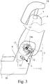
- the locking system 1 is equipped with a locking mechanism 5, the basic structure of which is shown in FIG Fig. 3 can be found.
- the function of the locking mechanism 5 is that the adjustment component 4 can be locked and unlocked mechanically in the locking positions.
- the locking mechanism 5 thus ensures that the adjusting component 4 locked in a locking position remains in this locking position until the adjusting component 4 is unlocked by means of the locking mechanism 5.
- the locking mechanism 5 has an in Fig. 3 illustrated actuating drive 6, through which the locking mechanism 5 can be unlocked by a motor. In this context, it should be pointed out that unlocking the locking mechanism 5 is equivalent to unlocking the adjustment component 4.
- the locking system 1 has a proximity sensor 7 which can be triggered by a predetermined operating event.
- the term “proximity sensor” is to be understood broadly in the present case. It not only includes at least one proximity sensor element 8, which is still to be explained and which is used to generate sensor signals, but also an evaluation unit that may be present, in which a decision is made about the presence of the predetermined operator control event.
- the triggering of the proximity sensor 7 corresponds in the present case to the state in which the predetermined operating event has been detected by the proximity sensor 7, in particular by the evaluation unit.
- the adjustment component 4 can be unlocked by a motor via the actuating drive 6 by triggering the proximity sensor 7.
- This can be provided via a direct coupling between the proximity sensor 7 and the actuating drive 6.
- a locking control 9 is provided, which on the one hand is connected to the proximity sensor 7 and the adjusting drive 6 is on the other hand coupled in terms of control. When the proximity sensor 7 is triggered, the locking control 9 activates the actuating drive 6 accordingly.
- the function of the proximity sensor 7 can be based on very different sensor principles.
- the proximity sensor 7 is a capacitive proximity sensor which has at least one capacitive proximity sensor element 8.
- the locking mechanism 5 is designed as a latching mechanism such that an adjustment of the adjustment component 4 into a locking position is accompanied by the locking mechanism 5 engaging in its locking state.
- the locking mechanism 5 allows locking of the adjustment component 4 in more than two locking positions. This means that there are at least two adjustment ranges, each of which lies between two locking positions.
- the detailed representation of Fig. 1 infer that the locking mechanism 5 allows locking of the adjustment component 4 in the three locking positions S 1 , S 2 and S 3 .
- the locking position S 1 is the foremost comfort locking position and the locking position S 2 is the rearmost comfort locking position, whereby the actual comfort locking position can be adapted to the body size of the operator.
- the locking position S 3 is finally a loading position with which an additional loading area can regularly be generated.
- a particularly intuitive operating system results from the fact that the operating event is defined as an approach of a body part, here a hand 10 of the operator, to the proximity sensor 7.
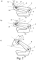
- the approach of the operator's hand 10 to the proximity sensor 7 results from the transition from Fig. 2a on Figure 2b .
- the arrangement is such that the unlocking is completed before the hand 10 of the operator comes into contact with the adjustment component 4, so that the manual adjustment of the adjustment component 4, here from the loading position of the backrest, can take place without delay.
- the manual adjustment of the backrest is in Figure 2c shown.
- the definition of the operating event includes exceeding a predetermined approach speed. This ensures, for example, that an inadvertent passage through the detection area of the proximity sensor 7 at a low approach speed is not detected as an operating event.
- the definition of the operating event includes exceeding a predetermined dwell time of the body part, here the hand, of the operator in the detection area of the proximity sensor 7. As a result, a further security has been created that an accidental passage through the detection area of the proximity sensor 7 is not detected as an operating event.
- the definition of the operating event includes touching the proximity sensor 7 or a cover of the proximity sensor 7 by a body part, here the hand, of the operator. This largely eliminates false tripping. However, it must be ensured that the unlocking of the adjusting component 4 takes place in good time so as not to hinder the manual adjustment by the operator.
- the locking mechanism 5 that is in the unlocked state automatically falls back into the locked state under a fallback condition.
- the fallback condition can be the expiry of a predetermined period of time since the proximity sensor 7 was triggered.
- Such a falling back of the locking mechanism 5 is particularly advantageous if the locking mechanism 5, as mentioned above, is designed to be latching.
- the actuating drive 6 has an actuating motor 11 and a gear 12 connected downstream of the actuating motor 11. With a corresponding gear ratio, the actuating motor 11 can be designed to be comparatively weak and thus inexpensive.
- FIG Fig. 3 A mechanically robust and at the same time cost-effective design of the transmission is shown in FIG Fig. 3 .
- the transmission 12 is switched off as a traction mechanism with a flexible traction mechanism 13, here and preferably as a cable transmission.
- the traction mechanism is designed in the manner of a pulley block, here and preferably in the manner of a two-stage pulley block. In general, however, the pulley block can be a single or multi-stage pulley block.
- the flexible traction means 13 is preferably designed as a rope. Alternatively, however, the flexible traction means can also be designed as a belt with a flat cross section or as a chain with several chain links. In particular, when the traction means is designed as a rope or belt, the running noise of the actuating drive 6 can be kept low with a robust mechanical structure.
- the locking mechanism 5 is here and preferably equipped with an unlocking lever 14, which is used to unlock the adjustment component 4, in Fig. 3 clockwise, is deflected by means of the actuating drive 6 about the pivot axis 14a.
- the seat arrangement 2 of the motor vehicle 3, which is equipped with a proposed locking system 1 is claimed as such. Reference may be made to all statements relating to the proposed locking system 1.
- the arrangement of the proximity sensor 7 is of particular importance.
- the proximity sensor 7 is arranged in or on the adjustment component 4 itself.
- the proximity sensor 7 is preferably arranged in a grip area 15 of the adjustment component 4 for manual adjustment thereof. It is therefore the grip area 15 that the operator can use would take intuitively for the manual adjustment of the adjustment component 4 anyway. In this respect, a particularly intuitive operating method results.
- the adjustment component 4 is designed as an adjustable backrest, the proximity sensor 7 being arranged on the end region 17 of the backrest facing away from the seat part 16 of the seat arrangement 2. This in turn corresponds to the basic idea of arranging the proximity sensor 7 at a point that the operator would take to manually adjust the adjustment component 4 anyway.
- a particularly high level of operating convenience can be achieved in that the adjustment component 4 is assigned a spring arrangement (not shown) to support its manual adjustment.
- the motor-driven unlocking of the locking mechanism 5 causes the adjustment component 4 to pop open at least from one locking position.
- the adjustment component 4 here the backrest, is only in the position shown in FIG Fig. 1 ⁇ adjustment range shown is freely adjustable by the spring arrangement.
- the spring arrangement In order to move from the ⁇ adjustment range into the locking position S 3 , the spring arrangement must be tensioned over the ⁇ adjustment range. When it is subsequently unlocked, the adjustment component 4 jumps into Fig. 1 clockwise, which simplifies the manual adjustment process.
- the spring arrangement is again to be tensioned over at least part of the ⁇ -adjustment range, which in turn leads to a corresponding opening of the adjustment component 4 during unlocking.
- Other configurations of the spring arrangement are conceivable.
- the described method for the operation of a proposed seat arrangement 2 is claimed as such. What is essential here is the fact that when the proximity sensor 7 is triggered, the adjustment component 4 is unlocked by a motor via the actuating drive 6, so that a subsequent manual adjustment of the adjustment component 4 is possible. Again, reference may be made to all statements relating to the operation of the proposed seat arrangement 2.
- the seat arrangement 2 has a motor-driven movement component to which a movement drive (not shown) is assigned.
- a movement drive (not shown) is assigned.
- the movement component is moved by a motor via the movement drive.
- the adjustment component 4 is then the backrest of the seat arrangement 2, while the displacement component is a seat part of the seat arrangement 2.
Landscapes
- Engineering & Computer Science (AREA)
- Aviation & Aerospace Engineering (AREA)
- Transportation (AREA)
- Mechanical Engineering (AREA)
- Human Computer Interaction (AREA)
- Seats For Vehicles (AREA)
- Chairs For Special Purposes, Such As Reclining Chairs (AREA)
Description
- Die vorliegende Erfindung betrifft ein Verriegelungssystem für eine Sitzanordnung eines Kraftfahrzeugs gemäß Anspruch 1, eine Sitzanordnung eines Kraftfahrzeugs mit einem solchen Verriegelungssystem gemäß Anspruch 9 sowie ein Verfahren für den Betrieb einer solchen Sitzanordnung gemäß Anspruch 12.
- Im Rahmen der Komforterhöhung bei Kraftfahrzeugen kommt der Unterstützung des Bedieners bei der Verstellung der Sitzanordnung des Kraftfahrzeugs besondere Bedeutung zu. Entsprechend sind die heutigen Sitzanordnungen mit einer Vielzahl von Verstellantrieben ausgestattet.
- Bekannt ist es beispielsweise, dem Sitzteil einer Sitzanordnung einen Verfahrantrieb zuzuordnen, über den das Sitzteil entsprechend längsverfahrbar ist (
DE 10 2011 018 378 A1 ). Ein besonders komfortables Verfahren des Sitzteils ergibt sich bei der bekannten Anordnung dadurch, dass das Längsverfahren des Sitzteils durch eine Annäherung eines Körperteils an eine Sensoranordnung bewirkt werden kann. Eine andere Anordnung mit Verfahrantrieb ist in derDE 199 61 874 C1 gezeigt. - Mit der bekannten Anordnung lässt sich ein hoher Bedienkomfort dadurch erreichen, dass der Bediener von sämtlichen manuellen Verstellaktivitäten entlastet wird. Dies allerdings nur, sofern es gelingt, in Echtzeit auf die Gestik des Bedieners zu reagieren. Eine verzögerte Reaktion der Anordnung auf die Annäherung des Körperteils des Bedieners führt im ungünstigsten Fall dazu, dass der Bediener auf die Ausführung der motorischen Verstellung der jeweiligen Verstellkomponente warten muss. Dies ist für den beispielhaften Fall der Verstellung eines Sitzteils, die als solche praktisch mühelos und in besonders kurzer Zeit durch den Bediener durchgeführt werden kann, nicht akzeptabel.
- Im letztgenannten Fall verkehrt sich die eigentlich komfortsteigernde Wirkung der bekannten Anordnung ins Gegenteil, so dass im Ergebnis sogar eine rein manuell zu verstellende Sitzanordnung einen höheren Bedienkomfort erzeugen würde. Bei einer solchen manuellen Anordnung ist ein Verriegelungssystem zur Realisierung mindestens zweier Verriegelungsstellungen der jeweiligen Verstellkomponente vorgesehen, zwischen denen die Verstellkomponente manuell verstellbar ist. Dieses manuelle Verriegelungssystem, das den Ausgangspunkt für die vorliegende Erfindung bildet, ist zwar robust in der Anwendung, lässt sich in manchen Fällen jedoch nur mit großem Kraftaufwand entriegeln, so dass eine Steigerung des Bedienkomforts wiederum möglich erscheint.
- Eine manuelle Verstellbarkeit der Verstellkomponente ist in der
DE 10 2011 016 646 A1 offenbart. Dort ist ein motorisch betätigbares Verriegelungssystem mit einem in einer Mittelkonsole befindlichen Bedienelement vorgesehen. - Der Erfindung liegt das Problem zugrunde, das bekannte Verriegelungssystem derart auszugestalten und weiterzubilden, dass der Bedienkomfort mit einfachen konstruktiven Mitteln gesteigert wird.
- Das obige Problem wird bei einem Verriegelungssystem mit den Merkmalen von Anspruch 1 gelöst.
- Wesentlich ist zunächst die Erkenntnis, dass weder eine rein automatische Verstellung einer Verstellkomponente noch eine rein manuelle Verstellung einer Verstellkomponente einer Sitzanordnung den größtmöglichen Bedienkomfort ermöglichen kann. Es wird vorgeschlagen, lediglich das Entriegeln der Verstellkomponente automatisch durchzuführen und die manuelle Verstellung der Verstellkomponente, ggf. federunterstützt, dem Bediener zu überlassen. Damit ist der Bediener einerseits von der für ihn mühsarnen Entriegelung entlastet. Andererseits kann der Bediener die gewünschte Verstellung mit genau der Geschwindigkeit durchführen, die für ihn optimal ist. Eine solche teilautomatisierte Lösung schafft nicht nur den größtmöglichen Bedienkomfort, sie lässt sich auch mit einfachen konstruktiven Mitteln umsetzen.
- Im Einzelnen wird zunächst vorgeschlagen, dass die Sitzanordnung eine manuell in mindestens eine Verriegelungsstellung verstellbare Verstellkomponente, nämlich eine entsprechend verstellbare Rückenlehne, aufweist. Hierfür ist das Verriegelungssystem mit einer entsprechenden Verriegelungsmechanik ausgestattet, wobei die Verstellkomponente in der Verriegelungsstellung bzw. in den Verriegelungsstellungen mittels der Verriegelungsmechanik verriegelbar und entriegelbar ist.
- Die Verriegelungsmechanik weist ferner einen Betätigungsantrieb auf, durch den die Verriegelungsmechanik motorisch entriegelbar ist. Die motorische Entriegelung ist bewirkbar durch ein vorbestimmtes Bedienereignis, das über einen Näherungssensor des Verriegelungssystems erfassbar ist. Konkret wird der Näherungssensor durch das vorbestimmte Bedienereignis ausgelöst, was ein Entriegeln der Verstellkomponente über den Betätigungsantrieb bewirkt, so dass die Verstellkomponente vom Bediener, ggf. federgestützt, verstellbar ist.
- Mit der vorschlagsgemäßen Lösung kann auf einen Verfahrantrieb für das motorische Verfahren der Verstellkomponente vollständig verzichtet werden, ohne dass der Bedienkomfort eingeschränkt wird. Das bereits führt zu einer besonders einfachen mechanischen Realisierbarkeit der Sitzanordnung insgesamt.
- Grundsätzlich kann es vorgesehen sein, dass die Verstellkomponente über den Betätigungsantrieb nicht nur entriegelbar, sondern auch verriegelbar ist. Bei der besonders bevorzugten Ausgestaltung ist es allerdings so, dass die Verriegelung der Verstellkomponente im Rahmen der Verstellung der Verstellkomponente selbsttätig, nämlich durch ein Einrasten der Verriegelungsmechanik, stattfindet. Damit lässt sich der steuerungstechnische Aufbau weiter vereinfachen.
- Weitere bevorzugte Ausgestaltungen betreffen Varianten für die Definition des Bedienereignisses. Je nach Auslegung des Näherungssensors kann das Bedienereignis unterschiedlich komplex definiert werden.
- Insbesondere für den vorgenannten Fall, dass die Verriegelung auf ein Einrasten der Verriegelungsmechanik zurückgeht, kann es notwendig sein, dass die Verriegelungsmechanik nach dem Auslösen des Näherungssensors rechtzeitig in den Verriegelungszustand zurückfällt. Hier lässt sich ein zeitbasiertes Rückfallen der Verriegelungsmechanik besonders leicht umsetzen.
- Eine kostengünstige Ausgestaltung des Betätigungsantriebs zeigt eine Ausgestaltung, nach der das dem Betätigungsmotor nachgeschaltete Getriebe als Zugmittelgetriebe ausgestaltet ist. Hierdurch lässt sich die resultierende Getriebeübersetzung mit geringen Kosten in einem weiten Bereich einstellen.
- Nach einer weiteren Lehre, der eigenständige Bedeutung zukommt, wird eine Sitzanordnung eines Kraftfahrzeugs mit einem vorschlagsgemäßen Verriegelungssystem als solche beansprucht.
- Die vorschlagsgemäße Sitzanordnung weist entsprechend eine manuell in mindestens eine Verriegelungsstellung verstellbare Verstellkomponente auf, wobei die Verstellkomponente in der Verriegelungsstellung bzw. in den Verriegelungsstellungen mittels der Verriegelungsmechanik verriegelbar und entriegelbar ist. Im Übrigen darf auf alle Erläuterungen zu dem vorschlagsgemäßen Verriegelungssystem verwiesen werden.
- Die weiter bevorzugten Ausgestaltungen betreffen Anordnungen des Näherungssensors, die hinsichtlich des Bedienkomforts besonders vorteilhaft sind. Grundsätzlich wird vorgeschlagen, den Näherungssensor in oder an der Verstellkomponente selbst anzuordnen, da der Bediener sich mit einer Hand ohnehin an die Verstellkomponente annähern muss, um die Verstellkomponente nach der Entriegelung manuell zu verstellen. Insoweit ist es besonders vorteilhaft, wenn die motorische Entriegelung abgeschlossen ist, wenn der Bediener die Verstellkomponente kontaktiert.
- Wie oben angedeutet, kann die manuelle Verstellung der Verstellkomponente federgestützt vorgesehen sein. Entsprechend wird vorgeschlagen, dass der Verstellkomponente eine entsprechende Federanordnung zur Unterstützung ihrer Verstellung zugeordnet ist. Je nach Ausgestaltung der Federanordnung kann es hier auch vorgesehen sein, dass die Verstellung der Verstellkomponente in einer Verstellrichtung vollständig federgetrieben erfolgt, während die Rückstellung der Verstellkomponente und damit das Spannen der Federanordnung entsprechend manuell durch den Bediener erfolgt.
- Nach einer weiteren Lehre, der ebenfalls eigenständige Bedeutung zukommt, wird das beschriebene Verfahren für den Betrieb einer vorschlagsgemäßen Sitzanordnung als solches beansprucht.
- Wesentlich für das vorschlagsgemäße Verfahren ist, dass durch das Auslösen des Näherungssensors die Verstellkomponente über den Betätigungsantrieb motorisch entriegelt wird, so dass anschließend eine manuelle Verstellung der Verstellkomponente durch den Bediener möglich ist. Insoweit darf auf alle Ausführungen zum Betrieb der vorschlagsgemäßen Sitzanordnung verwiesen werden.
- Interessant ist die bevorzugte Ausgestaltung des Verfahrens, bei der zusätzlich zu der Verstellkomponente eine motorisch verfahrbare Verfahrkomponente vorgesehen ist. Dabei ist es so, dass durch das Auslösen des Näherungssensors nicht nur die Verstellkomponente über den Betätigungsantrieb motorisch entriegelt wird, sondern auch die Verfahrkomponente über den Verfahrantrieb motorisch verfahren wird. Dies kann besonders vorteilhaft bei der sogenannten "Easy-Entry-Funktion" Anwendung finden, bei der zusätzlich zu dem Umklappen einer Rückenlehne einer Sitzanordnung gleichzeitig auch ein Verfahren des Sitzteils der Sitzanordnung nach vorne vorgesehen ist, so dass das Einsteigen des Bedieners im hinteren Sitzbereich vereinfacht wird.
- Im Folgenden wird die Erfindung anhand einer lediglich ein Ausführungsbeispiel darstellenden Zeichnung näher erläutert. In der Zeichnung zeigt
- Fig. 1
- den Heckbereich eines Kraftfahrzeugs mit einer vorschlagsgemäßen Sitzanordnung in einer ganz schematischen Darstellung,
- Fig. 2
- die Entriegelung der Rückenlehne der vorschlagsgemäßen Sitzanordnung a) während einer ersten Phase des Bedienereignisses, b) in einer zweiten Phase des Bedienereignisses und c) während der manuellen Verstellung der Rückenlehne der Sitzanordnung und
- Fig. 3
- die Verriegelungsmechanik des Verriegelungssystems der Sitzanordnung gemäß
Fig. 1 in einer ganz schematischen Darstellung. - Das in der Zeichnung gezeigte Verriegelungssystem 1 ist einer Sitzanordnung 2 eines Kraftfahrzeugs 3 zugeordnet, die bei dem dargestellten und insoweit bevorzugten Ausführungsbeispiel Bestandteil einer hinteren Sitzreihe ist. Die in Rede stehende Sitzanordnung 2 kann jedoch an beliebiger Stelle des Kraftfahrzeugs 3 angeordnet sein und beispielsweise auch einen Vordersitz des Kraftfahrzeugs 3 bereitstellen.
- Die Sitzanordnung 2 weist eine Verstellkomponente 4 auf, die sich manuell in mindestens eine Verriegelungsstellung, hier und vorzugsweise zwischen verschiedenen Verriegelungsstellungen, verstellen lässt. Dies ist der Detaildarstellung von
Fig. 1 zu entnehmen. Bei der Verstellkomponente 4 kann es sich um irgendeine verstellbare Komponente der Sitzanordnung 2 handeln. Bei dem dargestellten und insoweit bevorzugten Ausführungsbeispiel handelt es sich bei der Verstellkomponente 4 um die Rückenlehne der Sitzanordnung 2. Alle Ausführungen zu der Rückenlehne der Sitzanordnung 2 gelten für alle anderen Varianten für die Verstellkomponente 4 entsprechend. - Das Verriegelungssystem 1 ist mit einer Verriegelungsmechanik 5 ausgestattet, deren grundsätzlicher Aufbau der Darstellung gemäß
Fig. 3 zu entnehmen ist. Die Funktion der Verriegelungsmechanik 5 besteht darin, dass die Verstellkomponente 4 in den Verriegelungsstellungen in mechanischer Hinsicht verriegelbar und entriegelbar ist. Die Verriegelungsmechanik 5 sorgt also dafür, dass die in einer Verriegelungsstellung verriegelte Verstellkomponente 4 in dieser Verriegelungsstellung verbleibt, bis ein Entriegeln der Verstellkomponente 4 mittels der Verriegelungsmechanik 5 erfolgt. - Die Verriegelungsmechanik 5 weist einen in
Fig. 3 dargestellten Betätigungsantrieb 6 auf, durch den die Verriegelungsmechanik 5 motorisch entriegelbar ist. In diesem Zusammenhang darf darauf hingewiesen werden, dass die Entriegelung der Verriegelungsmechanik 5 gleichbedeutend mit der Entriegelung der Verstellkomponente 4 ist. - Wesentlich ist nun, dass das Verriegelungssystem 1 einen Näherungssensor 7 aufweist, der durch ein vorbestimmtes Bedienereignis auslösbar ist. Der Begriff "Näherungssensor" ist vorliegend weit zu verstehen. Er umfasst nicht nur mindestens ein noch zu erläuterndes Näherungssensorelement 8, das der Erzeugung von Sensorsignalen dient, sondern auch eine eventuell vorhandene Auswerteeinheit, in der eine Entscheidung über das Vorliegen des vorbestimmten Bedienereignisses getroffen wird. Das Auslösen des Näherungssensors 7 entspricht vorliegend dem Zustand, in dem das vorbestimmte Bedienereignis vom Näherungssensor 7, insbesondere von der Auswerteeinheit, erfasst worden ist.
- Wesentlich ist weiter, dass durch das Auslösen des Näherungssensors 7 die Verstellkomponente 4 über den Betätigungsantrieb 6 motorisch entriegelbar ist. Dies kann über eine direkte Kopplung zwischen dem Näherungssensor 7 und dem Betätigungsantrieb 6 vorgesehen sein. Vorzugsweise ist es allerdings so, dass eine Verriegelungssteuerung 9 vorgesehen ist, die mit dem Näherungssensor 7 einerseits und dem Verstellantrieb 6 andererseits steuerungstechnisch gekoppelt ist. Die Verriegelungssteuerung 9 nimmt auf das Auslösen des Näherungssensors 7 eine entsprechende Ansteuerung des Betätigungsantriebs 6 vor.
- Die Funktion des Näherungssensors 7 kann auf ganz unterschiedlichen Sensorprinzipien basieren. Hier und vorzugsweise handelt es sich bei dem Näherungssensor 7 um einen kapazitiven Näherungssensor, der mindestens ein kapazitives Näherungssensorelement 8 aufweist.
- Grundsätzlich kann es vorgesehen sein, dass nicht nur das Entriegeln der Verstellkomponente 4, sondern auch das Verriegeln der Verstellkomponente 4 motorisch erfolgt. Hier und vorzugsweise ist die Verriegelungsmechanik 5 allerdings als rastende Mechanik ausgestaltet derart, dass eine Verstellung der Verstellkomponente 4 in eine Verriegelungsstellung mit einem Einrasten der Verriegelungsmechanik 5 in ihren Verriegelungszustand einhergeht.
- Bei dem dargestellten und insoweit bevorzugten Ausführungsbeispiel erlaubt die Verriegelungsmechanik 5 eine Verriegelung der Verstellkomponente 4 in mehr als zwei Verriegelungsstellungen. Dies bedeutet, dass mindestens zwei Verstellbereiche existieren, die jeweils zwischen zwei Verriegelungsstellungen liegen. Es lässt sich der Detaildarstellung von
Fig. 1 entnehmen, dass die Verriegelungsmechanik 5 eine Verriegelung der Verstellkomponente 4 in den drei Verriegelungsstellungen S1, S2 und S3 erlaubt. Dabei handelt es sich bei der Verriegelungsstellung S1 um die vorderste Komfort-Verriegelungsstellung und bei der Verriegelungsstellung S2 um die hinterste Komfort-Verriegelungsstellung, wobei die tatsächliche Komfort-Verriegelungsstellung an die Körpergröße des Bedieners angepasst werden kann. Bei der Verriegelungsstellung S3 handelt es sich schließlich um eine Beladestellung, mit der regelmäßig eine zusätzliche Ladefläche erzeugbar ist. - Eine besonders intuitive Bediensystematik ergibt sich nach einer bevorzugten Ausgestaltung dadurch, dass das Bedienereignis als eine Annäherung eines Körperteils, hier einer Hand 10 des Bedieners an den Näherungssensor 7 definiert ist. Die Annäherung der Hand 10 des Bedieners an den Näherungssensor 7 ergibt sich aus dem Übergang von
Fig. 2a aufFig. 2b . Vorzugsweise ist die Anordnung so getroffen, dass das Entriegeln abgeschlossen ist, bevor die Hand 10 des Bedieners in Kontakt mit der Verstellkomponente 4 kommt, so dass die manuelle Verstellung der Verstellkomponente 4, hier aus der Beladestellung der Rückenlehne heraus, verzögerungsfrei erfolgen kann. Die manuelle Verstellung der Rückenlehne ist inFig. 2c gezeigt. - Um Fehlauslösungen des Näherungssensors 7 zu vermeiden, ist es vorzugsweise vorgesehen, dass die Definition des Bedienereignisses das Übersteigen einer vorbestimmten Annäherungsgeschwindigkeit umfasst. Damit ist beispielsweise sichergestellt, dass ein versehentliches Durchlaufen des Erfassungsbereichs des Näherungssensors 7 mit geringer Annäherungsgeschwindigkeit nicht als Bedienereignis erfasst wird.
- Alternativ oder zusätzlich kann es vorgesehen sein, dass die Definition des Bedienereignisses das Übersteigen einer vorbestimmten Verweildauer des Körperteils, hier der Hand, des Bedieners im Erfassungsbereich des Näherungssensors 7 umfasst. Dadurch ist eine weitere Sicherheit dafür geschaffen worden, dass ein versehentliches Durchlaufen des Erfassungsbereichs des Näherungssensors 7 nicht als Bedienereignis erfasst wird.
- Weiter alternativ oder zusätzlich kann es vorgesehen sein, dass die Definition des Bedienereignisses eine Berührung des Näherungssensors 7 oder einer Abdeckung des Näherungssensors 7 durch ein Körperteil, hier die Hand, des Bedieners umfasst. Damit lassen sich Fehlauslösungen weitgehend ausschließen. Allerdings muss dafür gesorgt werden, dass das Entriegeln der Verstellkomponente 4 rechtzeitig erfolgt, um die manuelle Verstellung durch den Bediener nicht zu behindern.
- Je nach mechanischer Ausgestaltung der Verriegelungsmechanik 5 kann es vorteilhaft sein, dass die im Entriegelungszustand befindliche Verriegelungsmechanik 5 unter einer Rückfallbedingung selbsttätig in den Verriegelungszustand zurückfällt. Beispielsweise kann es sich bei der Rückfallbedingung um den Ablauf einer vorbestimmten Zeitdauer seit dem Auslösen des Näherungssensors 7 handeln. Ein solches Rückfallen der Verriegelungsmechanik 5 ist insbesondere vorteilhaft, wenn die Verriegelungsmechanik 5 wie oben angesprochen, rastend ausgestaltet ist.
- Es lässt sich der Darstellung gemäß
Fig. 3 entnehmen, dass der Betätigungsantrieb 6 einen Betätigungsmotor 11 und ein dem Betätigungsmotor 11 nachgeschaltetes Getriebe 12 aufweist. Bei einer entsprechenden Getriebeübersetzung lässt sich der Betätigungsmotor 11 vergleichsweise schwach und damit kostengünstig auslegen. Eine mechanisch robuste und gleichzeitig kostengünstige Ausgestaltung des Getriebes zeigt die Darstellung gemäßFig. 3 . Hier ist das Getriebe 12 als Zugmittelgetriebe mit einem flexiblen Zugmittel 13, hier und vorzugsweise als Seilzuggetriebe, ausgeschaltet. Bei dem dargestellten und insoweit bevorzugten Ausführungsbeispiel ist das Zugmittelgetriebe nach Art eines Flaschenzugs, hier und vorzugsweise nach Art eines zweistufigen Flaschenzugs, ausgestaltet. Ganz allgemein kann es sich bei dem Flaschenzug aber um einen Ein- oder mehrstufigen Flaschenzug handeln. - Das flexible Zugmittel 13 ist vorzugsweise als Seil ausgestaltet. Alternativ kann das flexible Zugmittel aber auch als Band mit flachem Querschnitt oder als Kette mit mehreren Kettengliedern ausgestaltet sein. Insbesondere bei der Ausgestaltung des Zugmittels als Seil oder Band lassen sich die Laufgeräusche des Betätigungsantriebs 6 bei robustem mechanischem Aufbau gering halten.
- Die Verriegelungsmechanik 5 ist hier und vorzugsweise mit einem Entriegelungshebel 14 ausgestattet, der zum Entriegeln der Verstellkomponente 4, in
Fig. 3 im Uhrzeigersinn, mittels des Betätigungsantriebs 6 um die Schwenkachse 14a ausgelenkt wird. - Nach einer weiteren Lehre, der eigenständige Bedeutung zukommt, wird die Sitzanordnung 2 des Kraftfahrzeugs 3, die mit einem vorschlagsgemäßen Verriegelungssystem 1 ausgestattet ist, als solche beansprucht. Auf alle Ausführungen zu dem vorschlagsgemäßen Verriegelungssystem 1 darf verwiesen werden.
- Bei der vorschlagsgemäßen Sitzanordnung 2 kommt der Anordnung des Näherungssensors 7 ganz besondere Bedeutung zu. Hier und vorzugsweise ist es vorgesehen, dass der Näherungssensor 7 in oder an der Verstellkomponente 4 selbst angeordnet ist. Wie in
Fig. 2 gezeigt, ist der Näherungssensor 7 vorzugsweise in einem Griffbereich 15 der Verstellkomponente 4 für deren manuellen Verstellung angeordnet. Es handelt sich also um den Griffbereich 15, den der Bediener ohnehin intuitiv für die manuelle Verstellung der Verstellkomponente 4 ergreifen würde. Insoweit ergibt sich eine besonders intuitive Bedienmethodik. - Wie weiter oben angesprochen, ist die Verstellkomponente 4 als verstellbare Rückenlehne ausgestaltet, wobei der Näherungssensor 7 an dem dem Sitzteil 16 der Sitzanordnung 2 abgewandten Endbereich 17 der Rückenlehne angeordnet ist. Dies entspricht wiederum der grundsätzlichen Idee, den Näherungssensor 7 an einer Stelle anzuordnen, die der Bediener für die manuelle Verstellung der Verstellkomponente 4 ohnehin ergreifen würde.
- Ein besonders hoher Bedienkomfort lässt sich dadurch erreichen, dass der Verstellkomponente 4 eine nicht dargestellte Federanordnung zur Unterstützung ihrer manuellen Verstellung zugeordnet ist. Dabei ist es vorzugsweise so, dass zumindest aus einer Verriegelungsstellung heraus das motorische Entriegeln der Verriegelungsmechanik 5 ein federgetriebenes Aufspringen der Verstellkomponente 4 bewirkt.
- Bei der dargestellten und insoweit bevorzugten Sitzanordnung 2 ist es so, dass die Verstellkomponente 4, hier die Rückenlehne, nur in dem in
Fig. 1 gezeigten Δ-Verstellbereich frei von der Federanordnung verstellbar ist. Um von dem Δ-Verstellbereich in die Verriegelungsstellung S3 zu gelangen, muss die Federanordnung über den β-Verstellbereich gespannt werden. Bei einem anschließenden Entriegeln springt die Verstellkomponente 4 inFig. 1 im Uhrzeigersinn auf, was den manuellen Verstellvorgang vereinfacht. - Für das Erreichen der Verriegelungsstellung S1 sowie der Verriegelungsstellung S2 ist wiederum die Federanordnung über zumindest einen Teil des α-Verstellbereichs zu spannen, was wiederum zu einem entsprechenden Aufspringen der Verstellkomponente 4 beim Entriegeln führt. Andere Ausgestaltungen der Federanordnung sind denkbar.
- Nach einer weiteren Lehre, der ebenfalls eigenständige Bedeutung zukommt, wird das beschriebene Verfahren für den Betrieb einer vorschlagsgemäßen Sitzanordnung 2 als solches beansprucht. Wesentlich dabei ist die Tatsache, dass durch das Auslösen des Näherungssensors 7 die Verstellkomponente 4 über den Betätigungsantrieb 6 motorisch entriegelt wird, so dass eine anschließende manuelle Verstellung der Verstellkomponente 4 möglich ist. Wiederum darf auf alle Ausführungen zu dem Betrieb der vorschlagsgemäßen Sitzanordnung 2 verwiesen werden.
- In einer besonders bevorzugten Variante des vorschlagsgemäßen Verfahrens ist es vorgesehen, dass die Sitzanordnung 2 eine motorisch verfahrbare Verfahrkomponente aufweist, der ein nicht dargestellter Verfahrantrieb zugeordnet ist. Durch das Auslösen des Näherungssensors 7 wird die Verfahrkomponente über den Verfahrantrieb motorisch verfahren. In besonders bevorzugter Ausgestaltung handelt es sich dann bei der Verstellkomponente 4 um die Rückenlehne der Sitzanordnung 2, während es sich bei der Verfahrkomponente um ein Sitzteil der Sitzanordnung 2 handelt. Durch das synchronisierte Entriegeln und Verfahren von Rückenlehne einerseits und Sitzteil andererseits lässt sich auf besonders elegante Weise die weiter oben bereits angesprochene "Easy-Entry-Funktion" umsetzen.
Claims (13)
- Verriegelungssystem für eine Sitzanordnung (2) eines Kraftfahrzeugs (3), die eine manuell in mindestens eine Verriegelungsstellung verstellbare Verstellkomponente (4), die als verstellbare Rückenlehne ausgestaltet ist, aufweist, wobei das Verriegelungssystem (1) eine Verriegelungsmechanik (5) aufweist und wobei die Verstellkomponente (4) in der Verriegelungsstellung mittels der Verriegelungsmechanik (5) verriegelbar und entriegelbar ist, wobei die Verriegelungsmechanik (5) einen Betätigungsantrieb (6) aufweist, durch den die Verriegelungsmechanik (5) motorisch entriegelbar ist,
dadurch gekennzeichnet,
dass das Verriegelungssystem (1) einen Näherungssensor (7) aufweist, der durch ein vorbestimmtes Bedienereignis auslösbar ist, dass durch das Auslösen des Näherungssensors (7) die Verstellkomponente (4) über den Betätigungsantrieb (6) motorisch entriegelbar ist und dass der Näherungssensor (7) dazu geeignet ist, an einem dem Sitzteil (16) der Sitzanordnung (2) abgewandten Endbereich der als verstellbare Rückenlehne ausgestalteten Verstellkomponente (4) angeordnet zu sein. - Verriegelungssystem nach Anspruch 1, dadurch gekennzeichnet, dass der Näherungssensor (7) mindestens ein kapazitives Näherungssensorelement (8) aufweist.
- Verriegelungssystem nach Anspruch 1 oder 2, dadurch gekennzeichnet, dass die Verriegelungsmechanik (5) als rastende Mechanik ausgestaltet ist derart, dass eine Verstellung der Verstellkomponente (4) in die Verriegelungsstellung mit einem Einrasten der Verriegelungsmechanik (5) in ihren Verriegelungszustand einhergeht.
- Verriegelungssystem nach einem der vorhergehenden Ansprüche, dadurch gekennzeichnet, dass das Bedienereignis als eine Annäherung eines Körperteils, insbesondere einer Hand (10), des Bedieners an den Näherungssensor (7) definiert ist, vorzugsweise, dass die Definition des Bedienereignisses das Übersteigen einer vorbestimmten Annäherungsgeschwindigkeit umfasst.
- Verriegelungssystem nach Anspruch 4, dadurch gekennzeichnet, dass die Definition des Bedienereignisses das Übersteigen einer vorbestimmten Verweildauer des Körperteils des Bedieners im Erfassungsbereich des Näherungssensors (7) umfasst.
- Verriegelungssystem nach einem der vorhergehenden Ansprüche, dadurch gekennzeichnet, dass die Definition des Bedienereignisses eine Berührung des Näherungssensors (7) oder einer Abdeckung des Näherungssensors (7) durch ein Körperteil, insbesondere eine Hand (10), des Bedieners umfasst.
- Verriegelungssystem nach einem der vorhergehenden Ansprüche, dadurch gekennzeichnet, dass die im Entriegelungszustand befindliche Verriegelungsmechanik (5) unter einer Rückfallbedingung selbsttätig in den Verriegelungszustand zurückfällt, vorzugsweise, dass die Rückfallbedingung der Ablauf einer vorbestimmten Zeitdauer seit dem Auslösen des Näherungssensors (7) ist.
- Verriegelungssystem nach einem der vorhergehenden Ansprüche, dadurch gekennzeichnet, dass der Betätigungsantrieb (6) einen Betätigungsmotor (11) und ein dem Betätigungsmotor (11) nachgeschaltetes Getriebe (12) aufweist, vorzugsweise, dass das Getriebe (12) als Zugmittelgetriebe, insbesondere als Seilzuggetriebe, ausgestaltet ist, weiter vorzugsweise, dass das Zugmittelgetriebe nach Art eines ein- oder mehrstufigen Flaschenzugs ausgestaltet ist.
- Sitzanordnung eines Kraftfahrzeugs mit einem Verriegelungssystem (1) nach einem der vorhergehenden Ansprüche, wobei die Sitzanordnung (2) eine manuell in mindestens eine Verriegelungsstellung verstellbare Verstellkomponente (4), die als verstellbare Rückenlehne ausgestaltet ist, aufweist, wobei das Verriegelungssystem (1) eine Verriegelungsmechanik (5) aufweist und wobei die Verstellkomponente (4) in der Verriegelungsstellung mittels der Verriegelungsmechanik (5) verriegelbar und entriegelbar ist und wobei der Näherungssensor (7) an einem dem Sitzteil (16) der Sitzanordnung (2) abgewandten Endbereich der als verstellbare Rückenlehne ausgestalteten Verstellkomponente (4) angeordnet ist.
- Sitzanordnung nach Anspruch 9, dadurch gekennzeichnet, dass der Näherungssensor in oder an der Verstellkomponente (4) angeordnet ist, vorzugsweise, dass der Näherungssensor (7) in einem Griffbereich der Verstellkomponente (4) für deren manuelle Verstellung angeordnet ist.
- Sitzanordnung nach einem der Ansprüche 9 oder 10, dadurch gekennzeichnet, dass der Verstellkomponente (4) eine Federanordnung zur Unterstützung ihrer manuellen Verstellung zugeordnet ist, vorzugsweise, dass zumindest aus einer Verriegelungsstellung heraus das motorische Entriegeln der Verriegelungsmechanik ein federgetriebenes Aufspringen der Verstellkomponente (4) bewirkt.
- Verfahren für den Betrieb einer Sitzanordnung nach einem der Ansprüche 9 bis 11, dadurch gekennzeichnet, dass durch das Auslösen des Näherungssensors (7) die Verstellkomponente (4) über den Betätigungsantrieb (6) motorisch entriegelt wird.
- Verfahren nach Anspruch 12, dadurch gekennzeichnet, dass die Sitzanordnung (2) eine motorisch verfahrbare Verfahrkomponente aufweist, der ein Verfahrantrieb zugeordnet ist und dass durch das Auslösen des Näherungssensors (7) die Verfahrkomponente über den Verfahrantrieb motorisch verfahren wird, vorzugsweise, dass die Verstellkomponente (4) eine Rückenlehne der Sitzanordnung (2) ist und dass die Verfahrkomponente ein Sitzteil (16) der Sitzanordnung (2) ist.
Applications Claiming Priority (1)
| Application Number | Priority Date | Filing Date | Title |
|---|---|---|---|
| DE102015115035.2A DE102015115035A1 (de) | 2015-09-08 | 2015-09-08 | Verriegelungssystem für eine Sitzanordnung eines Kraftfahrzeugs |
Publications (2)
| Publication Number | Publication Date |
|---|---|
| EP3144177A1 EP3144177A1 (de) | 2017-03-22 |
| EP3144177B1 true EP3144177B1 (de) | 2020-11-04 |
Family
ID=56737918
Family Applications (1)
| Application Number | Title | Priority Date | Filing Date |
|---|---|---|---|
| EP16182926.2A Active EP3144177B1 (de) | 2015-09-08 | 2016-08-05 | Verriegelungssystem für eine sitzanordnung eines kraftfahrzeugs |
Country Status (4)
| Country | Link |
|---|---|
| US (1) | US10279711B2 (de) |
| EP (1) | EP3144177B1 (de) |
| CN (1) | CN106494269B (de) |
| DE (1) | DE102015115035A1 (de) |
Families Citing this family (5)
| Publication number | Priority date | Publication date | Assignee | Title |
|---|---|---|---|---|
| DE102015115035A1 (de) * | 2015-09-08 | 2017-03-09 | Brose Fahrzeugteile Gmbh & Co. Kommanditgesellschaft, Bamberg | Verriegelungssystem für eine Sitzanordnung eines Kraftfahrzeugs |
| ES2780937B2 (es) * | 2019-02-25 | 2021-02-25 | Seat Sa | Asiento para un vehículo |
| CN111452691B (zh) * | 2020-05-14 | 2024-07-23 | 舟山市银岱汽车零部件有限公司 | 一种带拉绳的可折叠头枕 |
| GB2598324A (en) * | 2020-08-26 | 2022-03-02 | Daimler Ag | Seating device for a vehicle |
| CN113246825B (zh) * | 2021-06-30 | 2022-11-11 | 宜宾凯翼汽车有限公司 | 一种具有舒适性调节功能的汽车座椅 |
Family Cites Families (36)
| Publication number | Priority date | Publication date | Assignee | Title |
|---|---|---|---|---|
| DE3815080C2 (de) | 1988-05-04 | 1996-08-01 | Keiper Recaro Gmbh Co | Verstellbarer, in einem Fahrzeug anzuordnender Sitz |
| US6774505B1 (en) * | 1998-07-17 | 2004-08-10 | Lear Automotive Dearborn, Inc. | Vehicle switch assembly with proximity activated illumination |
| DE19947380A1 (de) * | 1999-10-01 | 2001-04-05 | Abb Research Ltd | Näherungssensor und Verfahren zu seinem Betrieb |
| DE19961874C1 (de) * | 1999-12-22 | 2001-07-12 | Audi Ag | Fahrzeugsitz |
| US6825752B2 (en) * | 2000-06-13 | 2004-11-30 | Siemens Vdo Automotive Corporation | Effortless entry system and method |
| FR2830804B1 (fr) * | 2001-10-15 | 2004-01-16 | Faurecia Sieges Automobile | Siege de vehicule comportant un dossier rabattable vers l'avant |
| CN1708672B (zh) * | 2002-10-31 | 2010-05-12 | 量研科技股份有限公司 | 电荷转移电容位置传感器 |
| JP4499092B2 (ja) * | 2003-05-12 | 2010-07-07 | ジョンソン・コントロールズ・ゲー・エム・ベー・ハー | 調整機構用装置、その調整機構及び方法 |
| JP4009953B2 (ja) * | 2003-05-14 | 2007-11-21 | オムロン株式会社 | 物体検知センサ |
| DE10336335B4 (de) * | 2003-08-08 | 2015-03-12 | Huf Hülsbeck & Fürst Gmbh & Co. Kg | Schließvorrichtung für Fahrzeuge |
| GB2418493B (en) * | 2003-08-21 | 2006-11-15 | Harald Philipp | Capacitive position sensor |
| DE102005010594B4 (de) * | 2005-03-08 | 2010-09-16 | Brose Fahrzeugteile Gmbh & Co. Kommanditgesellschaft, Hallstadt | Lehne für einen Fahrzeugsitz |
| DE102006046515B4 (de) * | 2006-09-29 | 2015-12-31 | Ident Technology Ag | Kraftfahrzeugsitz mit einem Sensorsystem |
| JP4850042B2 (ja) * | 2006-11-29 | 2012-01-11 | 株式会社今仙電機製作所 | モータ駆動装置 |
| JP4531787B2 (ja) * | 2007-04-16 | 2010-08-25 | 株式会社フジクラ | パワーシート駆動装置 |
| US8091280B2 (en) * | 2007-06-01 | 2012-01-10 | GM Global Technology Operations LLC | Arms full vehicle closure activation apparatus and method |
| WO2009011275A1 (ja) * | 2007-07-13 | 2009-01-22 | Toyota Boshoku Kabushiki Kaisha | ロック解除機構 |
| DE102007044561C5 (de) * | 2007-09-07 | 2014-05-08 | Brose Fahrzeugteile Gmbh & Co. Kommanditgesellschaft, Hallstadt | Antriebsvorrichtung für eine Verstelleinrichtung eines Kraftfahrzeugs |
| DE102008062092B3 (de) * | 2008-12-10 | 2009-12-24 | Keiper Gmbh & Co. Kg | Fahrzeugsitz, insbesondere Kraftfahrzeugsitz |
| US20100185341A1 (en) * | 2009-01-16 | 2010-07-22 | Gm Global Technology Operations, Inc. | Vehicle mode activation by gesture recognition |
| JP5364926B2 (ja) * | 2009-03-31 | 2013-12-11 | 株式会社フジクラ | パワーシート駆動装置 |
| DE102009023386B4 (de) * | 2009-05-29 | 2025-01-16 | Volkswagen Ag | Sitz mit Indikator und Kraftfahrzeug |
| SE535896C2 (sv) * | 2010-12-14 | 2013-02-12 | Scania Cv Ab | System och anordning för styrning av fordonsstol |
| DE102011009229A1 (de) * | 2011-01-22 | 2012-07-26 | Daimler Ag | Gestensteuerung von Beifahrersitz, Gurtbringer oder Leseleuchte eines Fahrzeugs |
| DE102011016646A1 (de) * | 2011-04-09 | 2012-10-11 | GM Global Technology Operations LLC (n. d. Gesetzen des Staates Delaware) | Rückenlehnenverstellvorrichtung für einen Fahrzeugsitz oder eine Fahrzeugsitzbank |
| DE102011018378A1 (de) | 2011-04-21 | 2012-10-25 | Brose Fahrzeugteile Gmbh & Co. Kommanditgesellschaft, Coburg | Vorrichtung zur Positionierung eines Elements in einem Kraftfahrzeug |
| WO2013037465A1 (de) * | 2011-09-12 | 2013-03-21 | Reime Gerd | Optische messvorrichtung für ein fahrzeug und korrespondierendes fahrzeug |
| US9660644B2 (en) * | 2012-04-11 | 2017-05-23 | Ford Global Technologies, Llc | Proximity switch assembly and activation method |
| KR101316873B1 (ko) * | 2012-07-04 | 2013-10-08 | 현대자동차주식회사 | 게이트 작동 시스템 및 그 방법 |
| US8922340B2 (en) * | 2012-09-11 | 2014-12-30 | Ford Global Technologies, Llc | Proximity switch based door latch release |
| EP2835280A1 (de) * | 2013-08-07 | 2015-02-11 | Schukra Gerätebau GmbH | Entriegelungsaktuator und Verfahren zur Betätigung einer Sitzverriegelung |
| DE102013224282A1 (de) * | 2013-11-27 | 2015-05-28 | Bayerische Motoren Werke Aktiengesellschaft | Automatisches Verfahren eines durch Fremdkraft verfahrbaren Sitzes eines Personenkraftwagens bei Dauerbetätigung des Türaußengriffes |
| US10059232B2 (en) * | 2014-03-26 | 2018-08-28 | Faurecia Automotive Seating, Llc | Vehicle seat |
| WO2016133638A1 (en) * | 2015-02-20 | 2016-08-25 | Zodiac Seats Us Llc | Haptic system: recline activation control |
| US9713967B2 (en) * | 2015-03-26 | 2017-07-25 | Faurecia Automotive Seating, Llc | Vehicle seat |
| DE102015115035A1 (de) * | 2015-09-08 | 2017-03-09 | Brose Fahrzeugteile Gmbh & Co. Kommanditgesellschaft, Bamberg | Verriegelungssystem für eine Sitzanordnung eines Kraftfahrzeugs |
-
2015
- 2015-09-08 DE DE102015115035.2A patent/DE102015115035A1/de not_active Withdrawn
-
2016
- 2016-08-05 EP EP16182926.2A patent/EP3144177B1/de active Active
- 2016-09-07 CN CN201610806329.6A patent/CN106494269B/zh active Active
- 2016-09-08 US US15/259,591 patent/US10279711B2/en active Active
Non-Patent Citations (1)
| Title |
|---|
| None * |
Also Published As
| Publication number | Publication date |
|---|---|
| US20170066346A1 (en) | 2017-03-09 |
| US10279711B2 (en) | 2019-05-07 |
| EP3144177A1 (de) | 2017-03-22 |
| CN106494269B (zh) | 2020-02-07 |
| DE102015115035A1 (de) | 2017-03-09 |
| CN106494269A (zh) | 2017-03-15 |
Similar Documents
| Publication | Publication Date | Title |
|---|---|---|
| DE19507952C2 (de) | Schaltvorrichtung | |
| EP1997997A2 (de) | Verfahren zur motorischen Verstellung einer Kraftfahrzeugtür | |
| EP2900540B1 (de) | Lenksäule für ein kraftfahrzeug | |
| EP2078635A2 (de) | Sitzanordnung mit einer Zwangsführung | |
| EP3144177A1 (de) | Verriegelungssystem für eine sitzanordnung eines kraftfahrzeugs | |
| EP0116839A2 (de) | Vorrichtung zum Verlagern eines Gurtbandes | |
| DE102011107215A1 (de) | Kraftfahrzeugkarosserie mit einer Öffnung und einer schwenkbaren Klappe zum Verschließen der Öffnung | |
| DE102004049404B4 (de) | Vorrichtung zur Begrenzung der Einstellbarkeit einer Komponente, insbesondere eines Fahrzeugsitzes, auf einem sich längs erstreckenden Einstellbereich und Fahrzeugsitz | |
| DE10107196A1 (de) | Fahrzeugsitz, insbesondere Fluggastsitz | |
| DE102019003360A1 (de) | Fahrzeug-Türsystem mit Türöffner | |
| EP1663703B1 (de) | Sitz und verfahren | |
| DE19727536A1 (de) | Türhandgriff für Kraftfahrzeuge | |
| DE102010045418A1 (de) | Schwenksitz | |
| EP1075981B1 (de) | Betätigungsvorrichtung für eine Arretierung eines Fahrzeugsitzes | |
| DE10161647A1 (de) | Kfz-Sicherheitseinrichtung, insbesondere Laderaumabdeckung | |
| WO2020229135A1 (de) | Körperadaptive armauflagenanordnung | |
| DE202013102552U1 (de) | Verstellbarer Säulenverkleidungs-Haltegriff für ein Fahrzeug | |
| DE4205286C2 (de) | Steuerung für Antriebe | |
| DE102014114793B4 (de) | Fahrzeugkonsole mit einem Staufach und einer Rasteinrichtung | |
| DE102011120854A1 (de) | Sperreinrichtung, Verstellvorrichtung,Kraftfahrzeugsitz, Kraftfahrzeug und Verfahren hierzu | |
| DE102016114884A1 (de) | Kraftfahrzeuginnenraumanordnung mit einer Betätigungseinrichtung für ein Arretiersystem | |
| DE102004010592A1 (de) | Cockpit eines Kraftfahrzeugs mit einem Lenkrad und einem verstellbaren Sitz | |
| DE102006039582B4 (de) | Motorhauben-Auswurfsystem für ein Automobil im Falle einer Kollision mit einer Frontpartie des Fahrzeugs | |
| EP0286693B1 (de) | Kraftfahrzeugsitz, der durch Kippen seiner Rückenlehne längsverschiebbar ist | |
| DE102005005826A1 (de) | Kopfstütze |
Legal Events
| Date | Code | Title | Description |
|---|---|---|---|
| PUAI | Public reference made under article 153(3) epc to a published international application that has entered the european phase |
Free format text: ORIGINAL CODE: 0009012 |
|
| STAA | Information on the status of an ep patent application or granted ep patent |
Free format text: STATUS: THE APPLICATION HAS BEEN PUBLISHED |
|
| AK | Designated contracting states |
Kind code of ref document: A1 Designated state(s): AL AT BE BG CH CY CZ DE DK EE ES FI FR GB GR HR HU IE IS IT LI LT LU LV MC MK MT NL NO PL PT RO RS SE SI SK SM TR |
|
| AX | Request for extension of the european patent |
Extension state: BA ME |
|
| STAA | Information on the status of an ep patent application or granted ep patent |
Free format text: STATUS: REQUEST FOR EXAMINATION WAS MADE |
|
| 17P | Request for examination filed |
Effective date: 20170922 |
|
| RBV | Designated contracting states (corrected) |
Designated state(s): AL AT BE BG CH CY CZ DE DK EE ES FI FR GB GR HR HU IE IS IT LI LT LU LV MC MK MT NL NO PL PT RO RS SE SI SK SM TR |
|
| REG | Reference to a national code |
Ref country code: DE Ref legal event code: R079 Ref document number: 502016011591 Country of ref document: DE Free format text: PREVIOUS MAIN CLASS: B60N0002020000 Ipc: B60N0002120000 |
|
| RIC1 | Information provided on ipc code assigned before grant |
Ipc: B60N 2/12 20060101AFI20191111BHEP Ipc: B60N 2/02 20060101ALI20191111BHEP Ipc: B60N 2/235 20060101ALI20191111BHEP Ipc: B60N 2/874 20180101ALI20191111BHEP |
|
| GRAJ | Information related to disapproval of communication of intention to grant by the applicant or resumption of examination proceedings by the epo deleted |
Free format text: ORIGINAL CODE: EPIDOSDIGR1 |
|
| STAA | Information on the status of an ep patent application or granted ep patent |
Free format text: STATUS: GRANT OF PATENT IS INTENDED |
|
| GRAP | Despatch of communication of intention to grant a patent |
Free format text: ORIGINAL CODE: EPIDOSNIGR1 |
|
| INTG | Intention to grant announced |
Effective date: 20200114 |
|
| RAP1 | Party data changed (applicant data changed or rights of an application transferred) |
Owner name: BROSE FAHRZEUGTEILE SE & CO. KOMMANDITGESELLSCHAFT, BAMBERG |
|
| GRAJ | Information related to disapproval of communication of intention to grant by the applicant or resumption of examination proceedings by the epo deleted |
Free format text: ORIGINAL CODE: EPIDOSDIGR1 |
|
| STAA | Information on the status of an ep patent application or granted ep patent |
Free format text: STATUS: REQUEST FOR EXAMINATION WAS MADE |
|
| GRAS | Grant fee paid |
Free format text: ORIGINAL CODE: EPIDOSNIGR3 |
|
| STAA | Information on the status of an ep patent application or granted ep patent |
Free format text: STATUS: GRANT OF PATENT IS INTENDED |
|
| INTC | Intention to grant announced (deleted) | ||
| GRAP | Despatch of communication of intention to grant a patent |
Free format text: ORIGINAL CODE: EPIDOSNIGR1 |
|
| INTG | Intention to grant announced |
Effective date: 20200708 |
|
| GRAA | (expected) grant |
Free format text: ORIGINAL CODE: 0009210 |
|
| STAA | Information on the status of an ep patent application or granted ep patent |
Free format text: STATUS: THE PATENT HAS BEEN GRANTED |
|
| AK | Designated contracting states |
Kind code of ref document: B1 Designated state(s): AL AT BE BG CH CY CZ DE DK EE ES FI FR GB GR HR HU IE IS IT LI LT LU LV MC MK MT NL NO PL PT RO RS SE SI SK SM TR |
|
| REG | Reference to a national code |
Ref country code: GB Ref legal event code: FG4D Free format text: NOT ENGLISH |
|
| REG | Reference to a national code |
Ref country code: CH Ref legal event code: EP |
|
| REG | Reference to a national code |
Ref country code: AT Ref legal event code: REF Ref document number: 1330400 Country of ref document: AT Kind code of ref document: T Effective date: 20201115 |
|
| REG | Reference to a national code |
Ref country code: IE Ref legal event code: FG4D Free format text: LANGUAGE OF EP DOCUMENT: GERMAN |
|
| REG | Reference to a national code |
Ref country code: DE Ref legal event code: R096 Ref document number: 502016011591 Country of ref document: DE |
|
| REG | Reference to a national code |
Ref country code: NL Ref legal event code: MP Effective date: 20201104 |
|
| PG25 | Lapsed in a contracting state [announced via postgrant information from national office to epo] |
Ref country code: GR Free format text: LAPSE BECAUSE OF FAILURE TO SUBMIT A TRANSLATION OF THE DESCRIPTION OR TO PAY THE FEE WITHIN THE PRESCRIBED TIME-LIMIT Effective date: 20210205 Ref country code: FI Free format text: LAPSE BECAUSE OF FAILURE TO SUBMIT A TRANSLATION OF THE DESCRIPTION OR TO PAY THE FEE WITHIN THE PRESCRIBED TIME-LIMIT Effective date: 20201104 Ref country code: PT Free format text: LAPSE BECAUSE OF FAILURE TO SUBMIT A TRANSLATION OF THE DESCRIPTION OR TO PAY THE FEE WITHIN THE PRESCRIBED TIME-LIMIT Effective date: 20210304 Ref country code: RS Free format text: LAPSE BECAUSE OF FAILURE TO SUBMIT A TRANSLATION OF THE DESCRIPTION OR TO PAY THE FEE WITHIN THE PRESCRIBED TIME-LIMIT Effective date: 20201104 Ref country code: NO Free format text: LAPSE BECAUSE OF FAILURE TO SUBMIT A TRANSLATION OF THE DESCRIPTION OR TO PAY THE FEE WITHIN THE PRESCRIBED TIME-LIMIT Effective date: 20210204 |
|
| PG25 | Lapsed in a contracting state [announced via postgrant information from national office to epo] |
Ref country code: BG Free format text: LAPSE BECAUSE OF FAILURE TO SUBMIT A TRANSLATION OF THE DESCRIPTION OR TO PAY THE FEE WITHIN THE PRESCRIBED TIME-LIMIT Effective date: 20210204 Ref country code: IS Free format text: LAPSE BECAUSE OF FAILURE TO SUBMIT A TRANSLATION OF THE DESCRIPTION OR TO PAY THE FEE WITHIN THE PRESCRIBED TIME-LIMIT Effective date: 20210304 Ref country code: PL Free format text: LAPSE BECAUSE OF FAILURE TO SUBMIT A TRANSLATION OF THE DESCRIPTION OR TO PAY THE FEE WITHIN THE PRESCRIBED TIME-LIMIT Effective date: 20201104 Ref country code: SE Free format text: LAPSE BECAUSE OF FAILURE TO SUBMIT A TRANSLATION OF THE DESCRIPTION OR TO PAY THE FEE WITHIN THE PRESCRIBED TIME-LIMIT Effective date: 20201104 Ref country code: LV Free format text: LAPSE BECAUSE OF FAILURE TO SUBMIT A TRANSLATION OF THE DESCRIPTION OR TO PAY THE FEE WITHIN THE PRESCRIBED TIME-LIMIT Effective date: 20201104 Ref country code: ES Free format text: LAPSE BECAUSE OF FAILURE TO SUBMIT A TRANSLATION OF THE DESCRIPTION OR TO PAY THE FEE WITHIN THE PRESCRIBED TIME-LIMIT Effective date: 20201104 |
|
| REG | Reference to a national code |
Ref country code: LT Ref legal event code: MG9D |
|
| PG25 | Lapsed in a contracting state [announced via postgrant information from national office to epo] |
Ref country code: HR Free format text: LAPSE BECAUSE OF FAILURE TO SUBMIT A TRANSLATION OF THE DESCRIPTION OR TO PAY THE FEE WITHIN THE PRESCRIBED TIME-LIMIT Effective date: 20201104 |
|
| PG25 | Lapsed in a contracting state [announced via postgrant information from national office to epo] |
Ref country code: SK Free format text: LAPSE BECAUSE OF FAILURE TO SUBMIT A TRANSLATION OF THE DESCRIPTION OR TO PAY THE FEE WITHIN THE PRESCRIBED TIME-LIMIT Effective date: 20201104 Ref country code: RO Free format text: LAPSE BECAUSE OF FAILURE TO SUBMIT A TRANSLATION OF THE DESCRIPTION OR TO PAY THE FEE WITHIN THE PRESCRIBED TIME-LIMIT Effective date: 20201104 Ref country code: CZ Free format text: LAPSE BECAUSE OF FAILURE TO SUBMIT A TRANSLATION OF THE DESCRIPTION OR TO PAY THE FEE WITHIN THE PRESCRIBED TIME-LIMIT Effective date: 20201104 Ref country code: EE Free format text: LAPSE BECAUSE OF FAILURE TO SUBMIT A TRANSLATION OF THE DESCRIPTION OR TO PAY THE FEE WITHIN THE PRESCRIBED TIME-LIMIT Effective date: 20201104 Ref country code: SM Free format text: LAPSE BECAUSE OF FAILURE TO SUBMIT A TRANSLATION OF THE DESCRIPTION OR TO PAY THE FEE WITHIN THE PRESCRIBED TIME-LIMIT Effective date: 20201104 Ref country code: LT Free format text: LAPSE BECAUSE OF FAILURE TO SUBMIT A TRANSLATION OF THE DESCRIPTION OR TO PAY THE FEE WITHIN THE PRESCRIBED TIME-LIMIT Effective date: 20201104 |
|
| REG | Reference to a national code |
Ref country code: DE Ref legal event code: R097 Ref document number: 502016011591 Country of ref document: DE |
|
| PG25 | Lapsed in a contracting state [announced via postgrant information from national office to epo] |
Ref country code: DK Free format text: LAPSE BECAUSE OF FAILURE TO SUBMIT A TRANSLATION OF THE DESCRIPTION OR TO PAY THE FEE WITHIN THE PRESCRIBED TIME-LIMIT Effective date: 20201104 |
|
| PLBE | No opposition filed within time limit |
Free format text: ORIGINAL CODE: 0009261 |
|
| STAA | Information on the status of an ep patent application or granted ep patent |
Free format text: STATUS: NO OPPOSITION FILED WITHIN TIME LIMIT |
|
| 26N | No opposition filed |
Effective date: 20210805 |
|
| PG25 | Lapsed in a contracting state [announced via postgrant information from national office to epo] |
Ref country code: NL Free format text: LAPSE BECAUSE OF FAILURE TO SUBMIT A TRANSLATION OF THE DESCRIPTION OR TO PAY THE FEE WITHIN THE PRESCRIBED TIME-LIMIT Effective date: 20201104 Ref country code: AL Free format text: LAPSE BECAUSE OF FAILURE TO SUBMIT A TRANSLATION OF THE DESCRIPTION OR TO PAY THE FEE WITHIN THE PRESCRIBED TIME-LIMIT Effective date: 20201104 Ref country code: IT Free format text: LAPSE BECAUSE OF FAILURE TO SUBMIT A TRANSLATION OF THE DESCRIPTION OR TO PAY THE FEE WITHIN THE PRESCRIBED TIME-LIMIT Effective date: 20201104 |
|
| PG25 | Lapsed in a contracting state [announced via postgrant information from national office to epo] |
Ref country code: SI Free format text: LAPSE BECAUSE OF FAILURE TO SUBMIT A TRANSLATION OF THE DESCRIPTION OR TO PAY THE FEE WITHIN THE PRESCRIBED TIME-LIMIT Effective date: 20201104 |
|
| PGFP | Annual fee paid to national office [announced via postgrant information from national office to epo] |
Ref country code: GB Payment date: 20210701 Year of fee payment: 6 |
|
| REG | Reference to a national code |
Ref country code: CH Ref legal event code: PL |
|
| PG25 | Lapsed in a contracting state [announced via postgrant information from national office to epo] |
Ref country code: MC Free format text: LAPSE BECAUSE OF FAILURE TO SUBMIT A TRANSLATION OF THE DESCRIPTION OR TO PAY THE FEE WITHIN THE PRESCRIBED TIME-LIMIT Effective date: 20201104 |
|
| REG | Reference to a national code |
Ref country code: BE Ref legal event code: MM Effective date: 20210831 |
|
| PG25 | Lapsed in a contracting state [announced via postgrant information from national office to epo] |
Ref country code: LI Free format text: LAPSE BECAUSE OF NON-PAYMENT OF DUE FEES Effective date: 20210831 Ref country code: CH Free format text: LAPSE BECAUSE OF NON-PAYMENT OF DUE FEES Effective date: 20210831 |
|
| PG25 | Lapsed in a contracting state [announced via postgrant information from national office to epo] |
Ref country code: IS Free format text: LAPSE BECAUSE OF FAILURE TO SUBMIT A TRANSLATION OF THE DESCRIPTION OR TO PAY THE FEE WITHIN THE PRESCRIBED TIME-LIMIT Effective date: 20210304 Ref country code: LU Free format text: LAPSE BECAUSE OF NON-PAYMENT OF DUE FEES Effective date: 20210805 |
|
| PG25 | Lapsed in a contracting state [announced via postgrant information from national office to epo] |
Ref country code: IE Free format text: LAPSE BECAUSE OF NON-PAYMENT OF DUE FEES Effective date: 20210805 Ref country code: BE Free format text: LAPSE BECAUSE OF NON-PAYMENT OF DUE FEES Effective date: 20210831 |
|
| REG | Reference to a national code |
Ref country code: AT Ref legal event code: MM01 Ref document number: 1330400 Country of ref document: AT Kind code of ref document: T Effective date: 20210805 |
|
| PG25 | Lapsed in a contracting state [announced via postgrant information from national office to epo] |
Ref country code: AT Free format text: LAPSE BECAUSE OF NON-PAYMENT OF DUE FEES Effective date: 20210805 |
|
| GBPC | Gb: european patent ceased through non-payment of renewal fee |
Effective date: 20220805 |
|
| PG25 | Lapsed in a contracting state [announced via postgrant information from national office to epo] |
Ref country code: HU Free format text: LAPSE BECAUSE OF FAILURE TO SUBMIT A TRANSLATION OF THE DESCRIPTION OR TO PAY THE FEE WITHIN THE PRESCRIBED TIME-LIMIT; INVALID AB INITIO Effective date: 20160805 |
|
| PG25 | Lapsed in a contracting state [announced via postgrant information from national office to epo] |
Ref country code: CY Free format text: LAPSE BECAUSE OF FAILURE TO SUBMIT A TRANSLATION OF THE DESCRIPTION OR TO PAY THE FEE WITHIN THE PRESCRIBED TIME-LIMIT Effective date: 20201104 |
|
| PG25 | Lapsed in a contracting state [announced via postgrant information from national office to epo] |
Ref country code: GB Free format text: LAPSE BECAUSE OF NON-PAYMENT OF DUE FEES Effective date: 20220805 |
|
| PG25 | Lapsed in a contracting state [announced via postgrant information from national office to epo] |
Ref country code: MK Free format text: LAPSE BECAUSE OF FAILURE TO SUBMIT A TRANSLATION OF THE DESCRIPTION OR TO PAY THE FEE WITHIN THE PRESCRIBED TIME-LIMIT Effective date: 20201104 |
|
| PG25 | Lapsed in a contracting state [announced via postgrant information from national office to epo] |
Ref country code: TR Free format text: LAPSE BECAUSE OF FAILURE TO SUBMIT A TRANSLATION OF THE DESCRIPTION OR TO PAY THE FEE WITHIN THE PRESCRIBED TIME-LIMIT Effective date: 20201104 |
|
| PG25 | Lapsed in a contracting state [announced via postgrant information from national office to epo] |
Ref country code: MT Free format text: LAPSE BECAUSE OF FAILURE TO SUBMIT A TRANSLATION OF THE DESCRIPTION OR TO PAY THE FEE WITHIN THE PRESCRIBED TIME-LIMIT Effective date: 20201104 |
|
| PGFP | Annual fee paid to national office [announced via postgrant information from national office to epo] |
Ref country code: FR Payment date: 20240702 Year of fee payment: 9 |
|
| PGFP | Annual fee paid to national office [announced via postgrant information from national office to epo] |
Ref country code: DE Payment date: 20250831 Year of fee payment: 10 |