EP3136428B1 - Chip zum montieren auf der oberfläche - Google Patents
Chip zum montieren auf der oberfläche Download PDFInfo
- Publication number
- EP3136428B1 EP3136428B1 EP16156430.7A EP16156430A EP3136428B1 EP 3136428 B1 EP3136428 B1 EP 3136428B1 EP 16156430 A EP16156430 A EP 16156430A EP 3136428 B1 EP3136428 B1 EP 3136428B1
- Authority
- EP
- European Patent Office
- Prior art keywords
- substrate
- chip
- metallization
- porous silicon
- opening
- Prior art date
- Legal status (The legal status is an assumption and is not a legal conclusion. Google has not performed a legal analysis and makes no representation as to the accuracy of the status listed.)
- Active
Links
Images


Classifications
-
- H—ELECTRICITY
- H10—SEMICONDUCTOR DEVICES; ELECTRIC SOLID-STATE DEVICES NOT OTHERWISE PROVIDED FOR
- H10W—GENERIC PACKAGES, INTERCONNECTIONS, CONNECTORS OR OTHER CONSTRUCTIONAL DETAILS OF DEVICES COVERED BY CLASS H10
- H10W20/00—Interconnections in chips, wafers or substrates
- H10W20/40—Interconnections external to wafers or substrates, e.g. back-end-of-line [BEOL] metallisations or vias connecting to gate electrodes
-
- H—ELECTRICITY
- H10—SEMICONDUCTOR DEVICES; ELECTRIC SOLID-STATE DEVICES NOT OTHERWISE PROVIDED FOR
- H10W—GENERIC PACKAGES, INTERCONNECTIONS, CONNECTORS OR OTHER CONSTRUCTIONAL DETAILS OF DEVICES COVERED BY CLASS H10
- H10W20/00—Interconnections in chips, wafers or substrates
- H10W20/01—Manufacture or treatment
- H10W20/031—Manufacture or treatment of conductive parts of the interconnections
- H10W20/032—Manufacture or treatment of conductive parts of the interconnections of conductive barrier, adhesion or liner layers
- H10W20/033—Manufacture or treatment of conductive parts of the interconnections of conductive barrier, adhesion or liner layers in openings in dielectrics
-
- H—ELECTRICITY
- H10—SEMICONDUCTOR DEVICES; ELECTRIC SOLID-STATE DEVICES NOT OTHERWISE PROVIDED FOR
- H10D—INORGANIC ELECTRIC SEMICONDUCTOR DEVICES
- H10D62/00—Semiconductor bodies, or regions thereof, of devices having potential barriers
- H10D62/10—Shapes, relative sizes or dispositions of the regions of the semiconductor bodies; Shapes of the semiconductor bodies
- H10D62/117—Shapes of semiconductor bodies
-
- H—ELECTRICITY
- H10—SEMICONDUCTOR DEVICES; ELECTRIC SOLID-STATE DEVICES NOT OTHERWISE PROVIDED FOR
- H10D—INORGANIC ELECTRIC SEMICONDUCTOR DEVICES
- H10D62/00—Semiconductor bodies, or regions thereof, of devices having potential barriers
- H10D62/80—Semiconductor bodies, or regions thereof, of devices having potential barriers characterised by the materials
- H10D62/83—Semiconductor bodies, or regions thereof, of devices having potential barriers characterised by the materials being Group IV materials, e.g. B-doped Si or undoped Ge
-
- H—ELECTRICITY
- H10—SEMICONDUCTOR DEVICES; ELECTRIC SOLID-STATE DEVICES NOT OTHERWISE PROVIDED FOR
- H10P—GENERIC PROCESSES OR APPARATUS FOR THE MANUFACTURE OR TREATMENT OF DEVICES COVERED BY CLASS H10
- H10P50/00—Etching of wafers, substrates or parts of devices
-
- H—ELECTRICITY
- H10—SEMICONDUCTOR DEVICES; ELECTRIC SOLID-STATE DEVICES NOT OTHERWISE PROVIDED FOR
- H10P—GENERIC PROCESSES OR APPARATUS FOR THE MANUFACTURE OR TREATMENT OF DEVICES COVERED BY CLASS H10
- H10P50/00—Etching of wafers, substrates or parts of devices
- H10P50/20—Dry etching; Plasma etching; Reactive-ion etching
- H10P50/24—Dry etching; Plasma etching; Reactive-ion etching of semiconductor materials
- H10P50/242—Dry etching; Plasma etching; Reactive-ion etching of semiconductor materials of Group IV materials
-
- H—ELECTRICITY
- H10—SEMICONDUCTOR DEVICES; ELECTRIC SOLID-STATE DEVICES NOT OTHERWISE PROVIDED FOR
- H10P—GENERIC PROCESSES OR APPARATUS FOR THE MANUFACTURE OR TREATMENT OF DEVICES COVERED BY CLASS H10
- H10P50/00—Etching of wafers, substrates or parts of devices
- H10P50/60—Wet etching
- H10P50/64—Wet etching of semiconductor materials
- H10P50/642—Chemical etching
-
- H—ELECTRICITY
- H10—SEMICONDUCTOR DEVICES; ELECTRIC SOLID-STATE DEVICES NOT OTHERWISE PROVIDED FOR
- H10P—GENERIC PROCESSES OR APPARATUS FOR THE MANUFACTURE OR TREATMENT OF DEVICES COVERED BY CLASS H10
- H10P52/00—Grinding, lapping or polishing of wafers, substrates or parts of devices
-
- H—ELECTRICITY
- H10—SEMICONDUCTOR DEVICES; ELECTRIC SOLID-STATE DEVICES NOT OTHERWISE PROVIDED FOR
- H10P—GENERIC PROCESSES OR APPARATUS FOR THE MANUFACTURE OR TREATMENT OF DEVICES COVERED BY CLASS H10
- H10P54/00—Cutting or separating of wafers, substrates or parts of devices
-
- H—ELECTRICITY
- H10—SEMICONDUCTOR DEVICES; ELECTRIC SOLID-STATE DEVICES NOT OTHERWISE PROVIDED FOR
- H10P—GENERIC PROCESSES OR APPARATUS FOR THE MANUFACTURE OR TREATMENT OF DEVICES COVERED BY CLASS H10
- H10P90/00—Preparation of wafers not covered by a single main group of this subclass, e.g. wafer reinforcement
- H10P90/12—Preparing bulk and homogeneous wafers
- H10P90/15—Preparing bulk and homogeneous wafers by making porous regions on the surface
-
- H—ELECTRICITY
- H10—SEMICONDUCTOR DEVICES; ELECTRIC SOLID-STATE DEVICES NOT OTHERWISE PROVIDED FOR
- H10W—GENERIC PACKAGES, INTERCONNECTIONS, CONNECTORS OR OTHER CONSTRUCTIONAL DETAILS OF DEVICES COVERED BY CLASS H10
- H10W20/00—Interconnections in chips, wafers or substrates
- H10W20/01—Manufacture or treatment
- H10W20/031—Manufacture or treatment of conductive parts of the interconnections
- H10W20/032—Manufacture or treatment of conductive parts of the interconnections of conductive barrier, adhesion or liner layers
- H10W20/055—Manufacture or treatment of conductive parts of the interconnections of conductive barrier, adhesion or liner layers by formation methods other than physical vapour deposition [PVD], chemical vapour deposition [CVD] or liquid deposition
-
- H—ELECTRICITY
- H10—SEMICONDUCTOR DEVICES; ELECTRIC SOLID-STATE DEVICES NOT OTHERWISE PROVIDED FOR
- H10W—GENERIC PACKAGES, INTERCONNECTIONS, CONNECTORS OR OTHER CONSTRUCTIONAL DETAILS OF DEVICES COVERED BY CLASS H10
- H10W20/00—Interconnections in chips, wafers or substrates
- H10W20/01—Manufacture or treatment
- H10W20/031—Manufacture or treatment of conductive parts of the interconnections
- H10W20/056—Manufacture or treatment of conductive parts of the interconnections by filling conductive material into holes, grooves or trenches
- H10W20/057—Manufacture or treatment of conductive parts of the interconnections by filling conductive material into holes, grooves or trenches by selectively depositing, e.g. by using selective CVD or plating
-
- H—ELECTRICITY
- H10—SEMICONDUCTOR DEVICES; ELECTRIC SOLID-STATE DEVICES NOT OTHERWISE PROVIDED FOR
- H10W—GENERIC PACKAGES, INTERCONNECTIONS, CONNECTORS OR OTHER CONSTRUCTIONAL DETAILS OF DEVICES COVERED BY CLASS H10
- H10W20/00—Interconnections in chips, wafers or substrates
- H10W20/40—Interconnections external to wafers or substrates, e.g. back-end-of-line [BEOL] metallisations or vias connecting to gate electrodes
- H10W20/41—Interconnections external to wafers or substrates, e.g. back-end-of-line [BEOL] metallisations or vias connecting to gate electrodes characterised by their conductive parts
- H10W20/43—Layouts of interconnections
-
- H—ELECTRICITY
- H10—SEMICONDUCTOR DEVICES; ELECTRIC SOLID-STATE DEVICES NOT OTHERWISE PROVIDED FOR
- H10W—GENERIC PACKAGES, INTERCONNECTIONS, CONNECTORS OR OTHER CONSTRUCTIONAL DETAILS OF DEVICES COVERED BY CLASS H10
- H10W70/00—Package substrates; Interposers; Redistribution layers [RDL]
- H10W70/60—Insulating or insulated package substrates; Interposers; Redistribution layers
- H10W70/611—Insulating or insulated package substrates; Interposers; Redistribution layers for connecting multiple chips together
-
- H—ELECTRICITY
- H10—SEMICONDUCTOR DEVICES; ELECTRIC SOLID-STATE DEVICES NOT OTHERWISE PROVIDED FOR
- H10W—GENERIC PACKAGES, INTERCONNECTIONS, CONNECTORS OR OTHER CONSTRUCTIONAL DETAILS OF DEVICES COVERED BY CLASS H10
- H10W72/00—Interconnections or connectors in packages
- H10W72/20—Bump connectors, e.g. solder bumps or copper pillars; Dummy bumps; Thermal bumps
-
- H—ELECTRICITY
- H10—SEMICONDUCTOR DEVICES; ELECTRIC SOLID-STATE DEVICES NOT OTHERWISE PROVIDED FOR
- H10W—GENERIC PACKAGES, INTERCONNECTIONS, CONNECTORS OR OTHER CONSTRUCTIONAL DETAILS OF DEVICES COVERED BY CLASS H10
- H10W95/00—Packaging processes not covered by the other groups of this subclass
-
- H—ELECTRICITY
- H10—SEMICONDUCTOR DEVICES; ELECTRIC SOLID-STATE DEVICES NOT OTHERWISE PROVIDED FOR
- H10W—GENERIC PACKAGES, INTERCONNECTIONS, CONNECTORS OR OTHER CONSTRUCTIONAL DETAILS OF DEVICES COVERED BY CLASS H10
- H10W70/00—Package substrates; Interposers; Redistribution layers [RDL]
- H10W70/01—Manufacture or treatment
- H10W70/05—Manufacture or treatment of insulating or insulated package substrates, or of interposers, or of redistribution layers
-
- H—ELECTRICITY
- H10—SEMICONDUCTOR DEVICES; ELECTRIC SOLID-STATE DEVICES NOT OTHERWISE PROVIDED FOR
- H10W—GENERIC PACKAGES, INTERCONNECTIONS, CONNECTORS OR OTHER CONSTRUCTIONAL DETAILS OF DEVICES COVERED BY CLASS H10
- H10W70/00—Package substrates; Interposers; Redistribution layers [RDL]
- H10W70/60—Insulating or insulated package substrates; Interposers; Redistribution layers
- H10W70/62—Insulating or insulated package substrates; Interposers; Redistribution layers characterised by their interconnections
- H10W70/65—Shapes or dispositions of interconnections
-
- H—ELECTRICITY
- H10—SEMICONDUCTOR DEVICES; ELECTRIC SOLID-STATE DEVICES NOT OTHERWISE PROVIDED FOR
- H10W—GENERIC PACKAGES, INTERCONNECTIONS, CONNECTORS OR OTHER CONSTRUCTIONAL DETAILS OF DEVICES COVERED BY CLASS H10
- H10W70/00—Package substrates; Interposers; Redistribution layers [RDL]
- H10W70/60—Insulating or insulated package substrates; Interposers; Redistribution layers
- H10W70/67—Insulating or insulated package substrates; Interposers; Redistribution layers characterised by their insulating layers or insulating parts
- H10W70/69—Insulating materials thereof
-
- H—ELECTRICITY
- H10—SEMICONDUCTOR DEVICES; ELECTRIC SOLID-STATE DEVICES NOT OTHERWISE PROVIDED FOR
- H10W—GENERIC PACKAGES, INTERCONNECTIONS, CONNECTORS OR OTHER CONSTRUCTIONAL DETAILS OF DEVICES COVERED BY CLASS H10
- H10W72/00—Interconnections or connectors in packages
- H10W72/01—Manufacture or treatment
- H10W72/019—Manufacture or treatment of bond pads
- H10W72/01931—Manufacture or treatment of bond pads using blanket deposition
- H10W72/01933—Manufacture or treatment of bond pads using blanket deposition in liquid form, e.g. spin coating, spray coating or immersion coating
- H10W72/01935—Manufacture or treatment of bond pads using blanket deposition in liquid form, e.g. spin coating, spray coating or immersion coating by plating, e.g. electroless plating or electroplating
-
- H—ELECTRICITY
- H10—SEMICONDUCTOR DEVICES; ELECTRIC SOLID-STATE DEVICES NOT OTHERWISE PROVIDED FOR
- H10W—GENERIC PACKAGES, INTERCONNECTIONS, CONNECTORS OR OTHER CONSTRUCTIONAL DETAILS OF DEVICES COVERED BY CLASS H10
- H10W72/00—Interconnections or connectors in packages
- H10W72/01—Manufacture or treatment
- H10W72/0198—Manufacture or treatment batch processes
-
- H—ELECTRICITY
- H10—SEMICONDUCTOR DEVICES; ELECTRIC SOLID-STATE DEVICES NOT OTHERWISE PROVIDED FOR
- H10W—GENERIC PACKAGES, INTERCONNECTIONS, CONNECTORS OR OTHER CONSTRUCTIONAL DETAILS OF DEVICES COVERED BY CLASS H10
- H10W72/00—Interconnections or connectors in packages
- H10W72/20—Bump connectors, e.g. solder bumps or copper pillars; Dummy bumps; Thermal bumps
- H10W72/29—Bond pads specially adapted therefor
-
- H—ELECTRICITY
- H10—SEMICONDUCTOR DEVICES; ELECTRIC SOLID-STATE DEVICES NOT OTHERWISE PROVIDED FOR
- H10W—GENERIC PACKAGES, INTERCONNECTIONS, CONNECTORS OR OTHER CONSTRUCTIONAL DETAILS OF DEVICES COVERED BY CLASS H10
- H10W72/00—Interconnections or connectors in packages
- H10W72/50—Bond wires
- H10W72/59—Bond pads specially adapted therefor
-
- H—ELECTRICITY
- H10—SEMICONDUCTOR DEVICES; ELECTRIC SOLID-STATE DEVICES NOT OTHERWISE PROVIDED FOR
- H10W—GENERIC PACKAGES, INTERCONNECTIONS, CONNECTORS OR OTHER CONSTRUCTIONAL DETAILS OF DEVICES COVERED BY CLASS H10
- H10W72/00—Interconnections or connectors in packages
- H10W72/90—Bond pads, in general
- H10W72/921—Structures or relative sizes of bond pads
- H10W72/922—Bond pads being integral with underlying chip-level interconnections
-
- H—ELECTRICITY
- H10—SEMICONDUCTOR DEVICES; ELECTRIC SOLID-STATE DEVICES NOT OTHERWISE PROVIDED FOR
- H10W—GENERIC PACKAGES, INTERCONNECTIONS, CONNECTORS OR OTHER CONSTRUCTIONAL DETAILS OF DEVICES COVERED BY CLASS H10
- H10W72/00—Interconnections or connectors in packages
- H10W72/90—Bond pads, in general
- H10W72/921—Structures or relative sizes of bond pads
- H10W72/923—Bond pads having multiple stacked layers
-
- H—ELECTRICITY
- H10—SEMICONDUCTOR DEVICES; ELECTRIC SOLID-STATE DEVICES NOT OTHERWISE PROVIDED FOR
- H10W—GENERIC PACKAGES, INTERCONNECTIONS, CONNECTORS OR OTHER CONSTRUCTIONAL DETAILS OF DEVICES COVERED BY CLASS H10
- H10W72/00—Interconnections or connectors in packages
- H10W72/90—Bond pads, in general
- H10W72/931—Shapes of bond pads
- H10W72/934—Cross-sectional shape, i.e. in side view
-
- H—ELECTRICITY
- H10—SEMICONDUCTOR DEVICES; ELECTRIC SOLID-STATE DEVICES NOT OTHERWISE PROVIDED FOR
- H10W—GENERIC PACKAGES, INTERCONNECTIONS, CONNECTORS OR OTHER CONSTRUCTIONAL DETAILS OF DEVICES COVERED BY CLASS H10
- H10W72/00—Interconnections or connectors in packages
- H10W72/90—Bond pads, in general
- H10W72/941—Dispositions of bond pads
- H10W72/9415—Dispositions of bond pads relative to the surface, e.g. recessed, protruding
-
- H—ELECTRICITY
- H10—SEMICONDUCTOR DEVICES; ELECTRIC SOLID-STATE DEVICES NOT OTHERWISE PROVIDED FOR
- H10W—GENERIC PACKAGES, INTERCONNECTIONS, CONNECTORS OR OTHER CONSTRUCTIONAL DETAILS OF DEVICES COVERED BY CLASS H10
- H10W72/00—Interconnections or connectors in packages
- H10W72/90—Bond pads, in general
- H10W72/951—Materials of bond pads
- H10W72/952—Materials of bond pads comprising metals or metalloids, e.g. PbSn, Ag or Cu
Definitions
- the present application concerns the field of semiconductor chips. It is more particularly aimed at so-called surface-mount chips, that is to say chips comprising, on at least one face, metallizations intended to be soldered to an external device, for example a printed circuit or another chip.
- FIG. 1A -C has the shape of a recessed vertical channel arranged in a vertical groove on the side of the chip, but it is not separated from the chip substrate by an insulating region.
- an insulation layer is placed between the front face of the substrate and the first portion of the metallization.
- the porous silicon region is in contact with the insulation layer in an overlap zone.
- the cutting strip has a width less than the width of the openings.
- the method comprises a step of grinding the lower face of the substrate.
- step c) the formation of the metallization comprises an electrochemical deposition step.
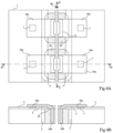
- THE figures 1A, 1B , 2A, 2B , 3A, 3B , 4A, 4B And 4C schematically represent steps of an example of an embodiment of a process for manufacturing a surface mount chip.
- THE figures 1B , 2B , 3B , 4B are sectional views according to plan BB of figures 1A , 2A , 3A , 4A .
- THE figures 1A And 2A are sectional views according to plan AA of the figures 1B And 2B .
- THE figures 3A And 4A are top views.
- There Figure 4C is a perspective view, cut according to plans BB and CC of the figure 4A .
- each of the chips comprises, in and on the substrate 1, an active zone 3 in which an electronic circuit is formed comprising one or more semiconductor components (not shown).
- the upper surface of the active zone 3 is entirely covered by an insulation layer 5, with the exception of one or more contact regions 7 connected to the electronic circuit.
- Steps described below relate more particularly to the production, in each chip, of at least one metallization intended to be soldered to an external device, this metallization comprising an upper portion in contact with one or more contact regions 7 of the chip, and a lateral portion on one side of the chip.
- FIGS. 1A and 1B represent a step in which we start from the substrate 1, in and on which the active zones 3, the insulation layer 5 and the contact regions 7 have been produced beforehand. At this stage, the cutting of the substrate into individual chips has not yet taken place.
- the active zones 3 of neighboring chips are separated, in top view, by spacer strips 9 inside each of which a cutting line 11 is defined. In the figures, only part of a spacer strip 9 and a corresponding part of a cutting line 11 are visible.
- the insulation layer 5 is removed, leaving the surface of the substrate 1 visible.
- the width of the strip 13 is less than the width of the spacing strip 9, and, seen from above, the strip 13 is strictly included in the strip 9, that is to say that the edges of the strip 13 are distant from the edges of the strip 9.
- the insulation layer 5 covers the substrate 1 in part of the spacing strip 9.
- one or more localized openings 15 are etched in the substrate 1, from the upper face of the substrate. In top view, each opening 15 is crossed by the cutting line 11 included in the strip 13. The dimension of the chips in the direction of the cutting line 11 is greater than the sum of the dimensions of the openings 15 along the line cutting. In other words at least one space 17 not engraved is held in the strip 13 between the chips along the cutting line 11.
- the openings 15 are visible, each being located between a contact region 7 of the chip located in the left part of the figures and a contact region 7 of the chip located in the right part of the figures.
- the openings 15 have, when viewed from above, the shape of rectangles, although other shapes are possible.
- the openings 15 extend, vertically, to a depth greater than the thickness of the substrate 1 occupied by the active parts 3.
- the openings 15 are not through, that is to say that they extend, vertically, to a depth less than the thickness of the substrate 1.
- the openings 15 can be through.
- the openings 15 can be produced by a plasma etching process, for example by an RIE type process, from English "Reactive Ion Etching". More generally, any other method making it possible to form localized openings in the spacer bands can be used, for example chemical or laser engraving.
- FIGS. 2A and 2B represent a step in which, after the step represented in Figures 1A and 1B , porous silicon regions 20 are formed in the substrate 1 from the side walls and the bottom of the openings 15.
- the porous silicon regions 20 are included inside the spacing strip 9. More particularly, in top view, each opening 15 is surrounded by a porous silicon region 20, which extends from the side walls of the opening 15 into portions of substrate 1 located under the insulation layer 5. Thus, in covering zones 22, portions of the porous silicon regions 20 have their upper faces in contact with the lower face of the insulation layer 5.
- the bottom and the side walls of each opening 15 are completely surrounded by a porous silicon region 20, so that the opening 15 is isolated from the rest of the substrate by the region 20.
- overlapping zones 22 are present on either side of the cutting line 11 at each opening 15.
- the porous silicon regions 20 can be produced for example by an electrochemical dissolution process.
- a mask which covers the upper face of the assembly of Figures 1A and 1B with the exception of openings 15 can be made.
- the assembly can then be immersed in a hydrofluoric acid solution between a first electrode facing the lower face of the assembly, and a second electrode facing the upper face of the assembly. assembly.
- the circulation of a current and possible lighting with an appropriate wavelength are adjusted so as to cause, at the level of the side walls and the bottom of the openings 15, the dissolution of part of the silicon of the substrate 1. in this way, at each opening 15, a region of the substrate 1 surrounding the opening 15 is transformed into porous silicon.
- the regions of porous silicon 20 associated with the different openings 15 are disjoint.
- an oxidation step of the porous silicon can be provided, for example by thermal oxidation.
- the oxidation of porous silicon makes it possible to increase the insulating properties of regions 20. This oxidation step is however optional.
- FIGS 3A and 3B represent a step in which, after the step represented in Figures 2A and 2B , metallizations 30 intended to be brazed to an external device are produced.
- Each metallization 30 includes at least at least one upper portion 30a covering part of the upper face or front face of at least one of the chips formed in and on the substrate 1, and a side portion 30b covering at least part of a side wall of an opening 15 bordering the chip.
- On each chip, at least one contact region 7 of the chip is in contact with an upper portion 30a of a metallization 30.
- each metallization 30 is produced, this metallization 30 covering the side walls and the bottom of the opening 15, and extending by a first upper portion 30a on the upper face of the chip located in the left part of the figure, and by a second upper portion 30a on the upper face of the chip located in the right part of the figure.
- each metallization 30 has its first upper portion 30a in contact with a contact region 7 of the chip located in the left part of the figure, and its second upper portion 30a in contact with a contact region 7 of the chip. chip located on the right side of the figure.
- the metallizations 30 are for example produced by an electrochemical deposition process.
- a mask not shown, can be made, this mask covering the entire upper face of the assembly of Figures 2A and 2B with the exception of places where metallizations must be deposited.
- a primer layer can then be deposited, for example by a spraying process. Once the primer layer has been deposited, an electrochemical deposition can be carried out from this primer layer, so as to form the metallizations 30.
- several successive electrochemical deposits can be carried out successively to obtain metallizations 30. comprising several layers of distinct metals. More generally, any other suitable deposition process can be used to form the metallizations 30.
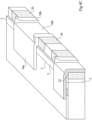
- FIGS. 4A, 4B And 4C represent a step in which, after the step represented in Figures 3A and 3B , the substrate 1 is cut into individual chips along each of the cutting lines 11, for example by sawing, by laser or chemical cutting, by cleavage, or by any other suitable cutting process.
- a strip or cutting zone 40 centered on the cutting line 11 is removed between two neighboring chips so as to dissociate the chips.
- the width of the openings 15 is greater than the width of the cutting strip 40. More particularly, the width of the openings 15 is chosen so that the lateral portions 30b of the metallizations 30 located on the sides of the chips are not removed during processing. cutting.
- the width L 15 of the openings 15 is such that L 15 - 2*e 30b > L 40 , e 30b being the thickness of the lateral portions 30b of the metallizations 30, and L 40 being the width of band 40.
- a preliminary step of grinding the lower face or rear face of the substrate 1 is carried out before the actual cutting step.
- the grinding step a part of the substrate 1 is removed over the entire surface of the assembly from the lower face of the substrate 1.
- the grinding is interrupted before reaching the active zones 3.
- the grinding is for example interrupted at an intermediate level between the upper face of the metallization portions 30 covering the bottom of the openings 15, and the lower face of the active zones 3.
- the openings 15 open onto the rear face of the substrate 1.
- the grinding can be interrupted before reaching the bottom of the openings 15.
- the grinding step can be omitted.
- each of the chips comprises at least one metallization 30 of which an upper portion 30a covers part of the upper face of the chip, and of which a side portion 30b covers part of a side of the chip, at least one region 7 of the chip being in contact with a portion upper 30a of a metallization 30.
- Each metallization 30 has its lateral portion 30b isolated from the rest of the substrate 1 by a region of porous silicon 20.
- the insulation of the upper portions 30a of the metallizations 30 is ensured in particular by the insulating layer 5.
- the covering zones 22 ensure continuity of the insulation between the insulation by the insulating layer 5 and the insulation by the porous silicon regions 20.
- Each metallization 30 is for example made up of a layer of copper covered with a layer of tin.
- the openings 15 have a width of between 50 ⁇ m and 100 ⁇ m
- the metallizations have a thickness of between 0.8 ⁇ m and 6 ⁇ m
- the cutting strips 40 have a width of between 10 ⁇ m and 30 ⁇ m.
- the porous silicon regions 20 have, for example, a thickness of between 10 and 50 ⁇ m.
- An advantage of the process described above is that it makes it possible to obtain chips having, on their front face, metallizations 30 intended to be soldered to an external device, these metallizations 30 extending onto part of the sides of the chip , which allows for a visual inspection of the quality of the connections.
- the lateral portions 30b of the metallizations 30 have hollow shapes. More particularly, in the example shown, the lateral portions 30b of the metallizations 30 have the shape of vertical channels arranged in vertical grooves located on the sides of the chip. This geometry makes it possible to improve the adhesion of the soldering material on the sides of the chip. In addition, this geometry facilitates visual inspection of the solder. In addition, this geometry makes it possible to locate the solder material inside the vertical channels, thus limiting the risk of short-circuiting between neighboring metallizations.
- non-etched spaces 17, maintained between the chips along the cutting line 11 during the step described in relation to the Figures 1A and 1B can receive elements useful for the manufacture of chips, such as, for example, alignment marks making it possible to facilitate the positioning of the substrate during the different stages of the process, etching control elements, or electrical control elements .
- the step described in relation to the Figures 1A and 1B removal of the insulation layer 5 in a strip 13 extending on either side of the cutting line 11, is optional.
- the insulation layer 5 can be kept in the strip 13, and the openings 15 made from the upper face of the insulation layer 5.
- the embodiments described are not limited to the example described in relation to the Figures 1A and 1B in which the openings 15 extend, vertically, over a depth greater than the thickness of the active zones 3 and less than the thickness of the substrate 1.
- the openings 15 formed in the step described in relation to the Figures 1A and 1B may have a depth less than the thickness of the active zones 3 or completely pass through the substrate 1.
- each of the upper and lower faces of the substrate can be provided with metallizations extending onto the sides of the substrate.
- metallizations of the lower face and metallizations of the upper face can be connected by metallization portions located on the sides of the substrate.
- the contacts can in this way be brought back towards metallizations of the upper face intended to be soldered to an external device.
- the contacts on the upper face can also be brought back in this way towards metallizations on the lower face intended to be soldered, for example, to another chip.
- the metallizations of the lower face can be independent of the metallizations of the upper face, that is to say not connected to metallizations of the upper face.
Landscapes
- Internal Circuitry In Semiconductor Integrated Circuit Devices (AREA)
- Physics & Mathematics (AREA)
- Geometry (AREA)
- Wire Bonding (AREA)
- Engineering & Computer Science (AREA)
- Plasma & Fusion (AREA)
- Chemical & Material Sciences (AREA)
- Chemical Kinetics & Catalysis (AREA)
- General Chemical & Material Sciences (AREA)
- Die Bonding (AREA)
Claims (8)
- Oberflächenmontage-Chip, der innerhalb und auf der Oberseite eines Siliziumsubstrats (1) mit einer Vorderseite und einer Seite ausgebildet ist, wobei der Chip Folgendes aufweist:
mindestens eine Metallisierung (30), die konfiguriert um mit einer externen Vorrichtung verlötet zu werden, wobei die Metallisierung einen ersten Abschnitt (30a), der mindestens einen Teil der Vorderseite des Substrats bedeckt, und einen zweiten Abschnitt (30b), der mindestens einen Teil der Seite des Substrats bedeckt, aufweist; dadurch gekennzeichnet, dass sie einen porösen Siliziumbereich (20) aufweist, der in dem Substrat enthalten ist und den zweiten Abschnitt (30b) der Metallisierung (30) vom Rest des Substrats isoliert, wobei der zweite Abschnitt (30b) der Metallisierung (30) die Form eines vertieften vertikalen Kanals hat, der in einer vertikalen Nut angeordnet ist, die sich auf der Seite des Substrats (1) befindet. - Chip nach Anspruch 1, der ferner Folgendes aufweist:einen aktiven Bereich (3), der innerhalb und auf der Oberseite des Substrats (1) ausgebildet ist und eine elektronische Schaltung enthält; undmindestens einen Kontaktbereich (7), der mit der elektronischen Schaltung verbunden ist und sich auf der Vorderseite des Chips befindet,wobei der erste Abschnitt (30a) der Metallisierung (30) mit dem Kontaktbereich (7) verbunden ist.
- Chip nach Anspruch 1 oder 2, wobei zwischen der Vorderseite des Substrats (1) und dem ersten Abschnitt (30a) der Metallisierung (30) eine Isolierschicht (5) angeordnet ist.
- Chip nach Anspruch 3, wobei mindestens ein Teil des porösen Siliziumbereichs (20) eine obere Fläche aufweist, die mit einer unteren Fläche der Isolierschicht (5) in Kontakt steht.
- Verfahren zum Ausbilden eines Oberflächenmontage-Chips innerhalb und auf einem Siliziumsubstrat (1), wobei das Verfahren die folgenden Schritte aufweista) Ätzen einer Öffnung (15) ausgehend von der Oberseite des Substrats (1), wobei diese Öffnung einen Teil einer Seite des Chips definiert;b) Ausbilden eines porösen Siliziumbereichs (20), der sich in dem Substrat (1) von den Seitenwänden der Öffnung (15) aus erstreckt;c) Ausbilden einer Metallisierung (30), die konfiguriert ist um an ein externes Bauelement gelötet zu werden, wobei die Metallisierung (30) einen ersten Abschnitt (30a) aufweist, der mindestens einen Teil der Oberseite des Substrats bedeckt und sich in einen zweiten Abschnitt (30b) erstreckt, der sich über die gesamte Oberfläche der Seitenwände der Öffnung (15) erstreckt, so dass der seitliche Abschnitt (30b) vom Rest des Substrats (1) durch einen Abschnitt aus porösem Silizium (20) isoliert ist; undd) Schneiden entlang eines Schneidbereichs (40), der auf einer die Öffnung (15) kreuzenden Schnittlinie (11) zentriert ist.
- Verfahren nach Anspruch 5, wobei der Schneidbereich (40) eine geringere Breite als die Breite der Öffnungen (15) aufweist.
- Verfahren nach Anspruch 5 oder 6, das einen Schritt des Schleifens der Unterseite des Substrats (1) aufweist.
- Verfahren nach einem der Ansprüche 5 bis 7, wobei im Schritt c) das Ausbilden der Metallisierung (30) einen elektrochemischen Abscheidungsschritt aufweist.
Applications Claiming Priority (1)
| Application Number | Priority Date | Filing Date | Title |
|---|---|---|---|
| FR1558067A FR3040532B1 (fr) | 2015-08-31 | 2015-08-31 | Puce a montage en surface |
Publications (2)
| Publication Number | Publication Date |
|---|---|
| EP3136428A1 EP3136428A1 (de) | 2017-03-01 |
| EP3136428B1 true EP3136428B1 (de) | 2023-12-13 |
Family
ID=54329794
Family Applications (1)
| Application Number | Title | Priority Date | Filing Date |
|---|---|---|---|
| EP16156430.7A Active EP3136428B1 (de) | 2015-08-31 | 2016-02-19 | Chip zum montieren auf der oberfläche |
Country Status (4)
| Country | Link |
|---|---|
| US (2) | US9543247B1 (de) |
| EP (1) | EP3136428B1 (de) |
| CN (2) | CN106486441B (de) |
| FR (1) | FR3040532B1 (de) |
Families Citing this family (5)
| Publication number | Priority date | Publication date | Assignee | Title |
|---|---|---|---|---|
| FR3040532B1 (fr) * | 2015-08-31 | 2017-10-13 | St Microelectronics Tours Sas | Puce a montage en surface |
| FR3069102A1 (fr) * | 2017-07-13 | 2019-01-18 | Stmicroelectronics (Tours) Sas | Procede de fabrication de puces isolees lateralement |
| WO2020146994A1 (zh) * | 2019-01-15 | 2020-07-23 | 深圳市汇顶科技股份有限公司 | 芯片及芯片的制造方法 |
| DE102020103531A1 (de) * | 2020-02-11 | 2021-08-12 | RENA Technologies GmbH | Elektrode, deren Verwendung, Akkumulator sowie Verfahren zur Herstellung einer Elektrode |
| US20240105390A1 (en) * | 2022-09-23 | 2024-03-28 | Wolfspeed, Inc. | Device and process for implementing silicon carbide (sic) surface mount devices |
Citations (2)
| Publication number | Priority date | Publication date | Assignee | Title |
|---|---|---|---|---|
| US20090194880A1 (en) * | 2008-01-31 | 2009-08-06 | Alpha & Omega Semiconductor, Ltd. | Wafer level chip scale package and process of manufacture |
| US20120025298A1 (en) * | 2010-07-29 | 2012-02-02 | Alpha And Omega Semiconductor Incorporated | Wafer level chip scale package |
Family Cites Families (43)
| Publication number | Priority date | Publication date | Assignee | Title |
|---|---|---|---|---|
| US3640806A (en) * | 1970-01-05 | 1972-02-08 | Nippon Telegraph & Telephone | Semiconductor device and method of producing the same |
| US3962052A (en) * | 1975-04-14 | 1976-06-08 | International Business Machines Corporation | Process for forming apertures in silicon bodies |
| US4096619A (en) * | 1977-01-31 | 1978-06-27 | International Telephone & Telegraph Corporation | Semiconductor scribing method |
| US4437141A (en) | 1981-09-14 | 1984-03-13 | Texas Instruments Incorporated | High terminal count integrated circuit device package |
| RU2082258C1 (ru) * | 1991-08-14 | 1997-06-20 | Сименс АГ | Схемная структура с по меньшей мере одним конденсатором и способ ее изготовления |
| EP0563625A3 (en) * | 1992-04-03 | 1994-05-25 | Ibm | Immersion scanning system for fabricating porous silicon films and devices |
| US5637916A (en) | 1996-02-02 | 1997-06-10 | National Semiconductor Corporation | Carrier based IC packaging arrangement |
| JP2956606B2 (ja) | 1996-08-21 | 1999-10-04 | 日立エーアイシー株式会社 | 端面スルーホール配線板 |
| KR100237051B1 (ko) | 1996-12-28 | 2000-01-15 | 김영환 | 버텀리드 반도체 패키지 및 그 제조 방법 |
| JPH10207467A (ja) * | 1997-01-27 | 1998-08-07 | Citizen Electron Co Ltd | 表面実装型電磁発音体及びその製造方法 |
| US6255156B1 (en) * | 1997-02-07 | 2001-07-03 | Micron Technology, Inc. | Method for forming porous silicon dioxide insulators and related structures |
| US6153489A (en) * | 1997-12-22 | 2000-11-28 | Electronics And Telecommunications Research Institute | Fabrication method of inductor devices using a substrate conversion technique |
| JP3877410B2 (ja) | 1997-12-26 | 2007-02-07 | 三洋電機株式会社 | 半導体装置の製造方法 |
| JP2000294719A (ja) | 1999-04-09 | 2000-10-20 | Hitachi Ltd | リードフレームおよびそれを用いた半導体装置ならびにその製造方法 |
| JP3429246B2 (ja) | 2000-03-21 | 2003-07-22 | 株式会社三井ハイテック | リードフレームパターン及びこれを用いた半導体装置の製造方法 |
| JP4477202B2 (ja) | 2000-07-12 | 2010-06-09 | ローム株式会社 | 半導体装置およびその製造方法 |
| US6569698B2 (en) * | 2000-12-07 | 2003-05-27 | Harvatek Corp. | Focusing cup on a folded frame for surface mount optoelectric semiconductor package |
| ITMI20011965A1 (it) | 2001-09-21 | 2003-03-21 | St Microelectronics Srl | Conduttori di un contenitore del tipo no-lead di un dispositivo semiconduttore |
| SG102639A1 (en) * | 2001-10-08 | 2004-03-26 | Micron Technology Inc | Apparatus and method for packing circuits |
| US6608366B1 (en) | 2002-04-15 | 2003-08-19 | Harry J. Fogelson | Lead frame with plated end leads |
| US7153754B2 (en) * | 2002-08-29 | 2006-12-26 | Micron Technology, Inc. | Methods for forming porous insulators from “void” creating materials and structures and semiconductor devices including same |
| JP4864307B2 (ja) * | 2003-09-30 | 2012-02-01 | アイメック | エアーギャップを選択的に形成する方法及び当該方法により得られる装置 |
| DE10351028B4 (de) * | 2003-10-31 | 2005-09-08 | Infineon Technologies Ag | Halbleiter-Bauteil sowie dafür geeignetes Herstellungs-/Montageverfahren |
| JP2008505434A (ja) * | 2004-04-27 | 2008-02-21 | テル アビブ ユニバーシティ フューチャー テクノロジー ディベロップメント リミティド パートナーシップ | インターレース型のマイクロコンテナ構造に基づく3−dマイクロ電池 |
| US20060043534A1 (en) * | 2004-08-26 | 2006-03-02 | Kirby Kyle K | Microfeature dies with porous regions, and associated methods and systems |
| DE102005004160B4 (de) * | 2005-01-28 | 2010-12-16 | Infineon Technologies Ag | CSP-Halbleiterbaustein, Halbleiterschaltungsanordnung und Verfahren zum Herstellen des CSP-Halbleiterbausteins |
| WO2007082075A2 (en) * | 2006-01-11 | 2007-07-19 | The Regents Of The University Of California | Optical sensor for detecting chemical reaction activity |
| US7635899B2 (en) * | 2007-01-11 | 2009-12-22 | International Business Machines Corporation | Structure and method to form improved isolation in a semiconductor device |
| US20100133693A1 (en) | 2008-12-03 | 2010-06-03 | Texas Instruments Incorporated | Semiconductor Package Leads Having Grooved Contact Areas |
| US8163601B2 (en) * | 2010-05-24 | 2012-04-24 | Alpha & Omega Semiconductor, Inc. | Chip-exposed semiconductor device and its packaging method |
| US8163629B2 (en) | 2010-08-05 | 2012-04-24 | Infineon Technologies Ag | Metallization for chip scale packages in wafer level packaging |
| JP5675504B2 (ja) * | 2010-08-06 | 2015-02-25 | ルネサスエレクトロニクス株式会社 | 半導体装置、電子装置、及び半導体装置の製造方法 |
| US8850131B2 (en) | 2010-08-24 | 2014-09-30 | Advanced Micro Devices, Inc. | Memory request scheduling based on thread criticality |
| FR2969376B1 (fr) * | 2010-12-16 | 2013-09-27 | St Microelectronics Crolles 2 | Procédé de fabrication de puces de circuits intégrés |
| DE102011010248B3 (de) * | 2011-02-03 | 2012-07-12 | Infineon Technologies Ag | Ein Verfahren zum Herstellen eines Halbleiterbausteins |
| DE102011101035B4 (de) * | 2011-05-10 | 2014-07-10 | Infineon Technologies Ag | Ein Verfahren zum Herstelllen eines Anschlussgebiets an einer Seitenwand eines Halbleiterkörpers |
| US8906782B2 (en) * | 2011-11-07 | 2014-12-09 | Infineon Technologies Ag | Method of separating semiconductor die using material modification |
| US9466662B2 (en) * | 2012-12-28 | 2016-10-11 | Intel Corporation | Energy storage devices formed with porous silicon |
| KR102154112B1 (ko) * | 2013-08-01 | 2020-09-09 | 삼성전자주식회사 | 금속 배선들을 포함하는 반도체 장치 및 그 제조 방법 |
| TWI566409B (zh) * | 2014-08-26 | 2017-01-11 | 元太科技工業股份有限公司 | 電晶體及其製作方法 |
| CN104319340A (zh) * | 2014-11-05 | 2015-01-28 | 安徽荃富信息科技有限公司 | 一种led灯用防潮支架 |
| US9536679B2 (en) * | 2015-01-06 | 2017-01-03 | Johnny Duc Van Chiem | Trenched super/ultra capacitors and methods of making thereof |
| FR3040532B1 (fr) * | 2015-08-31 | 2017-10-13 | St Microelectronics Tours Sas | Puce a montage en surface |
-
2015
- 2015-08-31 FR FR1558067A patent/FR3040532B1/fr not_active Expired - Fee Related
-
2016
- 2016-02-19 EP EP16156430.7A patent/EP3136428B1/de active Active
- 2016-02-23 US US15/051,158 patent/US9543247B1/en active Active
- 2016-02-26 CN CN201610108758.6A patent/CN106486441B/zh active Active
- 2016-02-26 CN CN201620148484.9U patent/CN205609507U/zh not_active Expired - Lifetime
- 2016-12-02 US US15/367,364 patent/US20170084482A1/en not_active Abandoned
Patent Citations (2)
| Publication number | Priority date | Publication date | Assignee | Title |
|---|---|---|---|---|
| US20090194880A1 (en) * | 2008-01-31 | 2009-08-06 | Alpha & Omega Semiconductor, Ltd. | Wafer level chip scale package and process of manufacture |
| US20120025298A1 (en) * | 2010-07-29 | 2012-02-02 | Alpha And Omega Semiconductor Incorporated | Wafer level chip scale package |
Also Published As
| Publication number | Publication date |
|---|---|
| CN106486441B (zh) | 2020-12-04 |
| US9543247B1 (en) | 2017-01-10 |
| FR3040532A1 (fr) | 2017-03-03 |
| EP3136428A1 (de) | 2017-03-01 |
| US20170084482A1 (en) | 2017-03-23 |
| FR3040532B1 (fr) | 2017-10-13 |
| CN106486441A (zh) | 2017-03-08 |
| CN205609507U (zh) | 2016-09-28 |
Similar Documents
| Publication | Publication Date | Title |
|---|---|---|
| EP3136428B1 (de) | Chip zum montieren auf der oberfläche | |
| EP4092730A2 (de) | Herstellung von elektronischen chips | |
| FR2935536A1 (fr) | Procede de detourage progressif | |
| EP2973750B1 (de) | Verfahren zur herstellung von leuchtdioden | |
| EP2363879A2 (de) | Herstellungsverfahren einer Mehrschichtenstruktur mit Konturfräsen durch thermomechanische Effekte | |
| EP3432352A1 (de) | Herstellungsverfahren von seitlich isolierten chips | |
| EP3118920A1 (de) | Selbsttragende dünnschicht-batterie, und herstellungsverfahren einer solchen batterie | |
| EP1111669A1 (de) | Verfahren zur Herstellung von isolierten metallischen Verbindungsleitungen in integrierten Schaltkreisen | |
| FR3104317A1 (fr) | Procédé de fabrication de puces électroniques | |
| FR3104316A1 (fr) | Procédé de fabrication de puces électroniques | |
| FR3075466A1 (fr) | Couvercle de boitier de circuit electronique | |
| EP2339616B1 (de) | Vereinfachtes Herstellungsverfahren eines Hybridsubstrats | |
| EP4220674B1 (de) | Vertikaler kondensator | |
| EP3836235B1 (de) | Verfahren zum aufbringen einer strukturierten materialschicht | |
| FR3093592A1 (fr) | Circuit intégré comportant un condensateur tridimensionnel | |
| EP1180790B1 (de) | Kondensatorherstellung mit metallischen Elektroden | |
| FR2983343A1 (fr) | Procede de prevention d'une panne electrique dans un empilement de couches semi-conductrices, cellule cpv a substrat mince, et assemblage de cellule solaire | |
| EP3171395B1 (de) | Herstellung von verbindungen durch umbiegen von leiterelementen unter eine mikroelektronische vorrichtung wie einen chip | |
| EP2246890B1 (de) | Herstellungsmethode eines Bildgebermoduls | |
| EP3772746B1 (de) | Verfahren zur herstellung von durchgangsverbindungen durch ein substrat | |
| FR3103315A1 (fr) | Procédé de fabrication de puces électroniques | |
| EP4297548A1 (de) | Verfahren zur herstellung elektronischer bauelemente | |
| EP4589641A1 (de) | Verfahren zur herstellung elektronischer bauelemente | |
| FR3076658A1 (fr) | Procede de gravure d'une cavite dans un empilement de couches | |
| EP4300553A1 (de) | Selbstausgerichtete bindung durch hydrophiliekontrast |
Legal Events
| Date | Code | Title | Description |
|---|---|---|---|
| PUAI | Public reference made under article 153(3) epc to a published international application that has entered the european phase |
Free format text: ORIGINAL CODE: 0009012 |
|
| STAA | Information on the status of an ep patent application or granted ep patent |
Free format text: STATUS: REQUEST FOR EXAMINATION WAS MADE |
|
| 17P | Request for examination filed |
Effective date: 20160219 |
|
| AK | Designated contracting states |
Kind code of ref document: A1 Designated state(s): AL AT BE BG CH CY CZ DE DK EE ES FI FR GB GR HR HU IE IS IT LI LT LU LV MC MK MT NL NO PL PT RO RS SE SI SK SM TR |
|
| AX | Request for extension of the european patent |
Extension state: BA ME |
|
| STAA | Information on the status of an ep patent application or granted ep patent |
Free format text: STATUS: EXAMINATION IS IN PROGRESS |
|
| 17Q | First examination report despatched |
Effective date: 20190712 |
|
| GRAP | Despatch of communication of intention to grant a patent |
Free format text: ORIGINAL CODE: EPIDOSNIGR1 |
|
| STAA | Information on the status of an ep patent application or granted ep patent |
Free format text: STATUS: GRANT OF PATENT IS INTENDED |
|
| RIC1 | Information provided on ipc code assigned before grant |
Ipc: H01L 21/306 20060101ALI20230615BHEP Ipc: H01L 21/78 20060101ALI20230615BHEP Ipc: H01L 23/485 20060101ALI20230615BHEP Ipc: H01L 21/60 20060101AFI20230615BHEP |
|
| INTG | Intention to grant announced |
Effective date: 20230712 |
|
| RIN1 | Information on inventor provided before grant (corrected) |
Inventor name: ORY, OLIVIER |
|
| GRAS | Grant fee paid |
Free format text: ORIGINAL CODE: EPIDOSNIGR3 |
|
| GRAA | (expected) grant |
Free format text: ORIGINAL CODE: 0009210 |
|
| STAA | Information on the status of an ep patent application or granted ep patent |
Free format text: STATUS: THE PATENT HAS BEEN GRANTED |
|
| AK | Designated contracting states |
Kind code of ref document: B1 Designated state(s): AL AT BE BG CH CY CZ DE DK EE ES FI FR GB GR HR HU IE IS IT LI LT LU LV MC MK MT NL NO PL PT RO RS SE SI SK SM TR |
|
| REG | Reference to a national code |
Ref country code: GB Ref legal event code: FG4D Free format text: NOT ENGLISH |
|
| REG | Reference to a national code |
Ref country code: CH Ref legal event code: EP |
|
| REG | Reference to a national code |
Ref country code: DE Ref legal event code: R096 Ref document number: 602016084661 Country of ref document: DE |
|
| REG | Reference to a national code |
Ref country code: IE Ref legal event code: FG4D Free format text: LANGUAGE OF EP DOCUMENT: FRENCH |
|
| PG25 | Lapsed in a contracting state [announced via postgrant information from national office to epo] |
Ref country code: GR Free format text: LAPSE BECAUSE OF FAILURE TO SUBMIT A TRANSLATION OF THE DESCRIPTION OR TO PAY THE FEE WITHIN THE PRESCRIBED TIME-LIMIT Effective date: 20240314 |
|
| REG | Reference to a national code |
Ref country code: LT Ref legal event code: MG9D |
|
| PG25 | Lapsed in a contracting state [announced via postgrant information from national office to epo] |
Ref country code: LT Free format text: LAPSE BECAUSE OF FAILURE TO SUBMIT A TRANSLATION OF THE DESCRIPTION OR TO PAY THE FEE WITHIN THE PRESCRIBED TIME-LIMIT Effective date: 20231213 |
|
| REG | Reference to a national code |
Ref country code: NL Ref legal event code: MP Effective date: 20231213 |
|
| PG25 | Lapsed in a contracting state [announced via postgrant information from national office to epo] |
Ref country code: ES Free format text: LAPSE BECAUSE OF FAILURE TO SUBMIT A TRANSLATION OF THE DESCRIPTION OR TO PAY THE FEE WITHIN THE PRESCRIBED TIME-LIMIT Effective date: 20231213 |
|
| PG25 | Lapsed in a contracting state [announced via postgrant information from national office to epo] |
Ref country code: LT Free format text: LAPSE BECAUSE OF FAILURE TO SUBMIT A TRANSLATION OF THE DESCRIPTION OR TO PAY THE FEE WITHIN THE PRESCRIBED TIME-LIMIT Effective date: 20231213 Ref country code: GR Free format text: LAPSE BECAUSE OF FAILURE TO SUBMIT A TRANSLATION OF THE DESCRIPTION OR TO PAY THE FEE WITHIN THE PRESCRIBED TIME-LIMIT Effective date: 20240314 Ref country code: ES Free format text: LAPSE BECAUSE OF FAILURE TO SUBMIT A TRANSLATION OF THE DESCRIPTION OR TO PAY THE FEE WITHIN THE PRESCRIBED TIME-LIMIT Effective date: 20231213 Ref country code: BG Free format text: LAPSE BECAUSE OF FAILURE TO SUBMIT A TRANSLATION OF THE DESCRIPTION OR TO PAY THE FEE WITHIN THE PRESCRIBED TIME-LIMIT Effective date: 20240313 |
|
| REG | Reference to a national code |
Ref country code: AT Ref legal event code: MK05 Ref document number: 1641207 Country of ref document: AT Kind code of ref document: T Effective date: 20231213 |
|
| PG25 | Lapsed in a contracting state [announced via postgrant information from national office to epo] |
Ref country code: NL Free format text: LAPSE BECAUSE OF FAILURE TO SUBMIT A TRANSLATION OF THE DESCRIPTION OR TO PAY THE FEE WITHIN THE PRESCRIBED TIME-LIMIT Effective date: 20231213 |
|
| PG25 | Lapsed in a contracting state [announced via postgrant information from national office to epo] |
Ref country code: SE Free format text: LAPSE BECAUSE OF FAILURE TO SUBMIT A TRANSLATION OF THE DESCRIPTION OR TO PAY THE FEE WITHIN THE PRESCRIBED TIME-LIMIT Effective date: 20231213 Ref country code: RS Free format text: LAPSE BECAUSE OF FAILURE TO SUBMIT A TRANSLATION OF THE DESCRIPTION OR TO PAY THE FEE WITHIN THE PRESCRIBED TIME-LIMIT Effective date: 20231213 Ref country code: NO Free format text: LAPSE BECAUSE OF FAILURE TO SUBMIT A TRANSLATION OF THE DESCRIPTION OR TO PAY THE FEE WITHIN THE PRESCRIBED TIME-LIMIT Effective date: 20240313 Ref country code: NL Free format text: LAPSE BECAUSE OF FAILURE TO SUBMIT A TRANSLATION OF THE DESCRIPTION OR TO PAY THE FEE WITHIN THE PRESCRIBED TIME-LIMIT Effective date: 20231213 Ref country code: LV Free format text: LAPSE BECAUSE OF FAILURE TO SUBMIT A TRANSLATION OF THE DESCRIPTION OR TO PAY THE FEE WITHIN THE PRESCRIBED TIME-LIMIT Effective date: 20231213 Ref country code: HR Free format text: LAPSE BECAUSE OF FAILURE TO SUBMIT A TRANSLATION OF THE DESCRIPTION OR TO PAY THE FEE WITHIN THE PRESCRIBED TIME-LIMIT Effective date: 20231213 |
|
| PG25 | Lapsed in a contracting state [announced via postgrant information from national office to epo] |
Ref country code: IS Free format text: LAPSE BECAUSE OF FAILURE TO SUBMIT A TRANSLATION OF THE DESCRIPTION OR TO PAY THE FEE WITHIN THE PRESCRIBED TIME-LIMIT Effective date: 20240413 |
|
| PG25 | Lapsed in a contracting state [announced via postgrant information from national office to epo] |
Ref country code: CZ Free format text: LAPSE BECAUSE OF FAILURE TO SUBMIT A TRANSLATION OF THE DESCRIPTION OR TO PAY THE FEE WITHIN THE PRESCRIBED TIME-LIMIT Effective date: 20231213 Ref country code: AT Free format text: LAPSE BECAUSE OF FAILURE TO SUBMIT A TRANSLATION OF THE DESCRIPTION OR TO PAY THE FEE WITHIN THE PRESCRIBED TIME-LIMIT Effective date: 20231213 |
|
| PG25 | Lapsed in a contracting state [announced via postgrant information from national office to epo] |
Ref country code: SK Free format text: LAPSE BECAUSE OF FAILURE TO SUBMIT A TRANSLATION OF THE DESCRIPTION OR TO PAY THE FEE WITHIN THE PRESCRIBED TIME-LIMIT Effective date: 20231213 |
|
| PG25 | Lapsed in a contracting state [announced via postgrant information from national office to epo] |
Ref country code: SM Free format text: LAPSE BECAUSE OF FAILURE TO SUBMIT A TRANSLATION OF THE DESCRIPTION OR TO PAY THE FEE WITHIN THE PRESCRIBED TIME-LIMIT Effective date: 20231213 Ref country code: SK Free format text: LAPSE BECAUSE OF FAILURE TO SUBMIT A TRANSLATION OF THE DESCRIPTION OR TO PAY THE FEE WITHIN THE PRESCRIBED TIME-LIMIT Effective date: 20231213 Ref country code: RO Free format text: LAPSE BECAUSE OF FAILURE TO SUBMIT A TRANSLATION OF THE DESCRIPTION OR TO PAY THE FEE WITHIN THE PRESCRIBED TIME-LIMIT Effective date: 20231213 Ref country code: IT Free format text: LAPSE BECAUSE OF FAILURE TO SUBMIT A TRANSLATION OF THE DESCRIPTION OR TO PAY THE FEE WITHIN THE PRESCRIBED TIME-LIMIT Effective date: 20231213 Ref country code: IS Free format text: LAPSE BECAUSE OF FAILURE TO SUBMIT A TRANSLATION OF THE DESCRIPTION OR TO PAY THE FEE WITHIN THE PRESCRIBED TIME-LIMIT Effective date: 20240413 Ref country code: EE Free format text: LAPSE BECAUSE OF FAILURE TO SUBMIT A TRANSLATION OF THE DESCRIPTION OR TO PAY THE FEE WITHIN THE PRESCRIBED TIME-LIMIT Effective date: 20231213 Ref country code: CZ Free format text: LAPSE BECAUSE OF FAILURE TO SUBMIT A TRANSLATION OF THE DESCRIPTION OR TO PAY THE FEE WITHIN THE PRESCRIBED TIME-LIMIT Effective date: 20231213 Ref country code: AT Free format text: LAPSE BECAUSE OF FAILURE TO SUBMIT A TRANSLATION OF THE DESCRIPTION OR TO PAY THE FEE WITHIN THE PRESCRIBED TIME-LIMIT Effective date: 20231213 |
|
| PG25 | Lapsed in a contracting state [announced via postgrant information from national office to epo] |
Ref country code: PT Free format text: LAPSE BECAUSE OF FAILURE TO SUBMIT A TRANSLATION OF THE DESCRIPTION OR TO PAY THE FEE WITHIN THE PRESCRIBED TIME-LIMIT Effective date: 20240415 Ref country code: PL Free format text: LAPSE BECAUSE OF FAILURE TO SUBMIT A TRANSLATION OF THE DESCRIPTION OR TO PAY THE FEE WITHIN THE PRESCRIBED TIME-LIMIT Effective date: 20231213 |
|
| REG | Reference to a national code |
Ref country code: DE Ref legal event code: R097 Ref document number: 602016084661 Country of ref document: DE |
|
| PG25 | Lapsed in a contracting state [announced via postgrant information from national office to epo] |
Ref country code: MC Free format text: LAPSE BECAUSE OF FAILURE TO SUBMIT A TRANSLATION OF THE DESCRIPTION OR TO PAY THE FEE WITHIN THE PRESCRIBED TIME-LIMIT Effective date: 20231213 |
|
| REG | Reference to a national code |
Ref country code: CH Ref legal event code: PL |
|
| PG25 | Lapsed in a contracting state [announced via postgrant information from national office to epo] |
Ref country code: DK Free format text: LAPSE BECAUSE OF FAILURE TO SUBMIT A TRANSLATION OF THE DESCRIPTION OR TO PAY THE FEE WITHIN THE PRESCRIBED TIME-LIMIT Effective date: 20231213 |
|
| PG25 | Lapsed in a contracting state [announced via postgrant information from national office to epo] |
Ref country code: LU Free format text: LAPSE BECAUSE OF NON-PAYMENT OF DUE FEES Effective date: 20240219 |
|
| PLBE | No opposition filed within time limit |
Free format text: ORIGINAL CODE: 0009261 |
|
| STAA | Information on the status of an ep patent application or granted ep patent |
Free format text: STATUS: NO OPPOSITION FILED WITHIN TIME LIMIT |
|
| PG25 | Lapsed in a contracting state [announced via postgrant information from national office to epo] |
Ref country code: CH Free format text: LAPSE BECAUSE OF NON-PAYMENT OF DUE FEES Effective date: 20240229 |
|
| PG25 | Lapsed in a contracting state [announced via postgrant information from national office to epo] |
Ref country code: SI Free format text: LAPSE BECAUSE OF FAILURE TO SUBMIT A TRANSLATION OF THE DESCRIPTION OR TO PAY THE FEE WITHIN THE PRESCRIBED TIME-LIMIT Effective date: 20231213 |
|
| PG25 | Lapsed in a contracting state [announced via postgrant information from national office to epo] |
Ref country code: SI Free format text: LAPSE BECAUSE OF FAILURE TO SUBMIT A TRANSLATION OF THE DESCRIPTION OR TO PAY THE FEE WITHIN THE PRESCRIBED TIME-LIMIT Effective date: 20231213 Ref country code: LU Free format text: LAPSE BECAUSE OF NON-PAYMENT OF DUE FEES Effective date: 20240219 Ref country code: DK Free format text: LAPSE BECAUSE OF FAILURE TO SUBMIT A TRANSLATION OF THE DESCRIPTION OR TO PAY THE FEE WITHIN THE PRESCRIBED TIME-LIMIT Effective date: 20231213 Ref country code: CH Free format text: LAPSE BECAUSE OF NON-PAYMENT OF DUE FEES Effective date: 20240229 |
|
| 26N | No opposition filed |
Effective date: 20240916 |
|
| GBPC | Gb: european patent ceased through non-payment of renewal fee |
Effective date: 20240313 |
|
| REG | Reference to a national code |
Ref country code: BE Ref legal event code: MM Effective date: 20240229 |
|
| PG25 | Lapsed in a contracting state [announced via postgrant information from national office to epo] |
Ref country code: BE Free format text: LAPSE BECAUSE OF NON-PAYMENT OF DUE FEES Effective date: 20240229 |
|
| PG25 | Lapsed in a contracting state [announced via postgrant information from national office to epo] |
Ref country code: GB Free format text: LAPSE BECAUSE OF NON-PAYMENT OF DUE FEES Effective date: 20240313 |
|
| PG25 | Lapsed in a contracting state [announced via postgrant information from national office to epo] |
Ref country code: FR Free format text: LAPSE BECAUSE OF NON-PAYMENT OF DUE FEES Effective date: 20240229 |
|
| PG25 | Lapsed in a contracting state [announced via postgrant information from national office to epo] |
Ref country code: IE Free format text: LAPSE BECAUSE OF NON-PAYMENT OF DUE FEES Effective date: 20240219 |
|
| PG25 | Lapsed in a contracting state [announced via postgrant information from national office to epo] |
Ref country code: IE Free format text: LAPSE BECAUSE OF NON-PAYMENT OF DUE FEES Effective date: 20240219 Ref country code: GB Free format text: LAPSE BECAUSE OF NON-PAYMENT OF DUE FEES Effective date: 20240313 Ref country code: FR Free format text: LAPSE BECAUSE OF NON-PAYMENT OF DUE FEES Effective date: 20240229 Ref country code: BE Free format text: LAPSE BECAUSE OF NON-PAYMENT OF DUE FEES Effective date: 20240229 |
|
| PG25 | Lapsed in a contracting state [announced via postgrant information from national office to epo] |
Ref country code: CY Free format text: LAPSE BECAUSE OF FAILURE TO SUBMIT A TRANSLATION OF THE DESCRIPTION OR TO PAY THE FEE WITHIN THE PRESCRIBED TIME-LIMIT; INVALID AB INITIO Effective date: 20160219 |
|
| PG25 | Lapsed in a contracting state [announced via postgrant information from national office to epo] |
Ref country code: HU Free format text: LAPSE BECAUSE OF FAILURE TO SUBMIT A TRANSLATION OF THE DESCRIPTION OR TO PAY THE FEE WITHIN THE PRESCRIBED TIME-LIMIT; INVALID AB INITIO Effective date: 20160219 |
|
| PG25 | Lapsed in a contracting state [announced via postgrant information from national office to epo] |
Ref country code: FI Free format text: LAPSE BECAUSE OF FAILURE TO SUBMIT A TRANSLATION OF THE DESCRIPTION OR TO PAY THE FEE WITHIN THE PRESCRIBED TIME-LIMIT Effective date: 20231213 |
|
| REG | Reference to a national code |
Ref country code: DE Ref legal event code: R079 Ref document number: 602016084661 Country of ref document: DE Free format text: PREVIOUS MAIN CLASS: H01L0021600000 Ipc: H10W0070010000 |
|
| PG25 | Lapsed in a contracting state [announced via postgrant information from national office to epo] |
Ref country code: TR Free format text: LAPSE BECAUSE OF FAILURE TO SUBMIT A TRANSLATION OF THE DESCRIPTION OR TO PAY THE FEE WITHIN THE PRESCRIBED TIME-LIMIT Effective date: 20231213 |
|
| PGFP | Annual fee paid to national office [announced via postgrant information from national office to epo] |
Ref country code: DE Payment date: 20260121 Year of fee payment: 11 |