EP3130739B2 - Schwelle mit zusatzvorrichtung zur verringerung der barrierewirkung - Google Patents
Schwelle mit zusatzvorrichtung zur verringerung der barrierewirkung Download PDFInfo
- Publication number
- EP3130739B2 EP3130739B2 EP16183531.9A EP16183531A EP3130739B2 EP 3130739 B2 EP3130739 B2 EP 3130739B2 EP 16183531 A EP16183531 A EP 16183531A EP 3130739 B2 EP3130739 B2 EP 3130739B2
- Authority
- EP
- European Patent Office
- Prior art keywords
- sill
- threshold
- building
- grating
- door
- Prior art date
- Legal status (The legal status is an assumption and is not a legal conclusion. Google has not performed a legal analysis and makes no representation as to the accuracy of the status listed.)
- Active
Links
Images
Classifications
-
- E—FIXED CONSTRUCTIONS
- E06—DOORS, WINDOWS, SHUTTERS, OR ROLLER BLINDS IN GENERAL; LADDERS
- E06B—FIXED OR MOVABLE CLOSURES FOR OPENINGS IN BUILDINGS, VEHICLES, FENCES OR LIKE ENCLOSURES IN GENERAL, e.g. DOORS, WINDOWS, BLINDS, GATES
- E06B1/00—Border constructions of openings in walls, floors, or ceilings; Frames to be rigidly mounted in such openings
- E06B1/70—Sills; Thresholds
-
- E—FIXED CONSTRUCTIONS
- E06—DOORS, WINDOWS, SHUTTERS, OR ROLLER BLINDS IN GENERAL; LADDERS
- E06B—FIXED OR MOVABLE CLOSURES FOR OPENINGS IN BUILDINGS, VEHICLES, FENCES OR LIKE ENCLOSURES IN GENERAL, e.g. DOORS, WINDOWS, BLINDS, GATES
- E06B7/00—Special arrangements or measures in connection with doors or windows
- E06B7/14—Measures for draining-off condensed water or water leaking-in frame members for draining off condensation water, throats at the bottom of a sash
-
- E—FIXED CONSTRUCTIONS
- E06—DOORS, WINDOWS, SHUTTERS, OR ROLLER BLINDS IN GENERAL; LADDERS
- E06B—FIXED OR MOVABLE CLOSURES FOR OPENINGS IN BUILDINGS, VEHICLES, FENCES OR LIKE ENCLOSURES IN GENERAL, e.g. DOORS, WINDOWS, BLINDS, GATES
- E06B7/00—Special arrangements or measures in connection with doors or windows
- E06B7/26—Rain or draught deflectors, e.g. under sliding wings also protection against light for doors
Definitions
- the invention relates to a threshold with an additional device for reducing the barrier effect of the threshold, wherein the threshold comprises a horizontally running cover profile on the inside of the building and a threshold weather profile inclined and/or sloping towards the outside of the building on the outside.
- a typical threshold system is known that already meets the requirement for a step less than 2 cm high.
- the threshold used here essentially consists of three components, namely a base body extruded from plastic, a cover profile locked to it, which also forms the stop edge for the inner stop seal of the inward-opening door leaf on the inside of the room, and a threshold weather profile made of extruded aluminum that slopes outwards and has a vortex channel on the inside of the room.
- the vortex channel is necessary to allow rainwater that is pushed up the threshold weather profile when exposed to driving rain to flow off to the side. Due to the system, however, this vortex channel also forms a step and thus represents a certain barrier.
- a barrier-free threshold construction that meets the requirements for a zero threshold is known, in which a large-volume supplementary element is provided on the outside of the building in front of the actual threshold, running parallel to the length of the threshold, which forms a rainwater collection channel that allows the rainwater to be drained parallel to the length of the threshold. At the top or towards floor level, this rainwater collection channel is covered by a grating to allow the rainwater to pass into the rainwater collection channel.
- Such a construction is obviously very complex and can only be used to a limited extent in conjunction with conventional thresholds.
- the effect of the water drainage is limited, since rainwater that hits the area between the grating and the door is only partially drained away, so that the driving rain tightness of this construction is limited.
- FR 3 003 595 A1 From the FR 3 003 595 A1 is a threshold construction for disabled access to a building, in which a concrete base body running diagonally outwards is covered with a flat grating.
- the FR 3 003 595 A1 discloses all the features of the preamble of claim 1. Such constructions are, on the one hand, very complex to manufacture and very limited in use, since an individual threshold must be manufactured for each door width. Conventional thresholds made of extruded aluminum and/or extruded plastic cannot be used for this construction.
- the object of the present invention is therefore to provide a threshold or a door with a threshold which meets higher requirements both in terms of driving rain tightness and accessibility and yet is associated with limited effort in production and application.
- the invention solves this problem by means of a conventional threshold known per se with an additional device for reducing the barrier effect according to claim 1, preferably in conjunction with one or more of the features of claims 2 and 3, or by means of a door according to claim 4, preferably with one or more of the features of claims 5 and 6.
- the invention is therefore based on a commercially available threshold, such as that known from WO 2015/011092 A1 or the EP 1 932 997 A2 is known, in which a horizontally running cover profile is used on the inside of the building and a threshold weather profile that is inclined and/or sloping towards the outside of the building is used on the outside of the building, wherein a step, in particular a vortex channel, is formed between the threshold weather profile and the cover profile.
- a commercially available threshold such as that known from WO 2015/011092 A1 or the EP 1 932 997 A2 is known, in which a horizontally running cover profile is used on the inside of the building and a threshold weather profile that is inclined and/or sloping towards the outside of the building is used on the outside of the building, wherein a step, in particular a vortex channel, is formed between the threshold weather profile and the cover profile.
- This base threshold is available by the meter and can be cut to the desired length if required.
- the additional device used according to the invention comprises a threshold grating and means for fastening the threshold grating at a distance above the threshold weathering edge, so that the threshold grating, in the assembled state, runs with its upper side at least largely in the plane of the horizontally running cover profile of the inserted threshold and a water drainage channel is formed between the threshold grating and the threshold weathering edge.
- the additional device used according to the invention further comprises an outer cover profile running on the outside of the building in the longitudinal extension of the threshold, which, in the assembled state, runs at least largely with its surface in the same plane as the cover profile on the inside of the building and the threshold grating.
- the cover profile of the threshold used does not necessarily have to be a separate component, but can also be connected in one piece to the threshold base body and/or the threshold weather profile.
- the only essential aspect of the invention is that this area of the threshold used defines a plane that is continued by the threshold grid used according to the invention and the adjoining outer cover profile in the direction of the outside of the building.
- the threshold grate - viewed in the vertical direction - runs above the threshold weathering edge of the installed threshold, it is at least partially covered by the door leaf or a door leaf weathering edge that is usually placed on the outside of the door in the lower horizontal area when the door leaf is closed, so that a large part of the driving rain that hits it is already drained into the water drainage channel in the outer area of the threshold grate.
- the part of the threshold grate facing the inside of the building serves to catch any remaining water before it reaches the - possibly further - sealing area between the door leaf and the threshold.
- the bearing adapters arranged at a distance from one another in the longitudinal extension of the threshold are used as a means for the spaced fastening of the threshold grating above the threshold weathering edge, so that drainage slots from the water drainage channel to the outside of the building are formed between two bearing adapters.
- the rainwater collected in the water drainage channel does not flow in the direction of extension of the threshold, but rather transversely thereto in the direction from the inside of the building to the outside of the building.
- the bearing adapters advantageously have a shape on their underside that allows for easy attachment to the outside edge of the threshold weatherboard of the threshold used, and on their upper side they have a support surface for the threshold grating.
- all that is needed is a possibly uniform threshold grating and a bearing adapter adapted to the threshold.
- the additional device according to the invention is used together with a door leaf which has at least one, preferably several seals on its underside running in the longitudinal extension of the threshold, of which at least one seal rests on the threshold grating used according to the invention when the door is closed and divides this into a partial area on the inside of the building and a partial area on the outside of the building.
- the seals used can - as is generally known from the prior art - be, for example, brush seals, hose seals or lowerable seals, for example magnetically operated seals, or also a combination of such seals with one another and/or with, for example, an additional internal stop seal.
- the threshold grate used according to the invention - unless it is additionally screwed - can be lifted when the door is open and the water drainage channel underneath can be easily cleaned.
- the threshold grating used according to the invention has a short angled leg on its longitudinal edge on the inside of the building, with which the threshold grating rests directly on the threshold weather leg.
- the threshold grating is preferably made of metal, in particular of aluminum or particularly preferably of stainless steel, with the openings, in particular in the form of two or more rows of elongated holes running transversely to the longitudinal extent, which can be produced by punching.
- the present invention is by no means limited to inward-opening doors, but can also be used for outward-opening doors.
- a commercially available thermally insulated WO 2015/011092 A1 The known standard threshold 1, consisting of a plastic extruded base body 2, a plastic extruded cover profile 3, also called threshold cover, and a threshold weather bar 4 made of extruded aluminium, which slopes at an angle to the outside of the building 13, is used.
- the threshold weatherboard 4 On the inside of the building (in Fig. 1 On the left side, the threshold weatherboard 4 has a vortex channel 18 as a step 23, which would represent a certain barrier without the additional device according to the invention.
- a floor entry profile 8 can be seen ( Fig. 2 ), which rests on the actual building structure, for example a concrete slab.
- the additional device according to the invention comprises firstly several bearing adapters 5, which - as in Fig. 2 shown - at a distance of about 50-100 mm from each other on the outside edge of the threshold weather leg 4 using the screws 9. Between each 2 of these bearing adapters 5, rainwater that has penetrated into the water drainage channel 19 can therefore flow off in the direction of the arrows 20. The water flow is in Fig. 7 clarified again.
- the outer cover profile 6 which extends over the entire length of the threshold weather bar 4, is snapped onto the bearing adapter 5.
- the top of this outer cover profile 6 runs in the same plane "E" ( Fig. 4 ) as the upper side of the cover profile 3 on the building interior side 14 of the thermally broken standard threshold 1.
- Both the outer cover profile 6 and the inner cover profile 3 have a grooved structure to increase slip resistance.
- the threshold grating 7 is placed on the weather bar 11 and on the outside of the building on the bearing adapter 5.
- the threshold grating has a bevel on the inside of the building (see Fig. 4 in section), so that the threshold grid also runs flush with its upper side in the same plane "E" formed by the upper sides of the inner cover profile 3 and the outer cover profile 6 ( Fig. 4 ).
- the threshold grating 7 is made of stainless steel and has two rows of openings 22 designed as elongated holes. Between the two rows of openings 22, a narrow web is formed that runs in the longitudinal direction of the threshold extension, on which the hose seals 21, which also run over the entire extension of the threshold 1, rest when the door is closed. This divides the threshold grating 7 into an area on the inside of the building and an area on the outside of the building, so that rainwater that is pressed onto the threshold structure from the outside 13 of the building, for example by gusty wind, is largely drained in the area of the row of openings 22 on the outside of the building into the water drainage channel 19 that extends between the threshold grating 7 and the threshold weather profile 4. To the extent that a few drops of rainwater overcome the outer hose seal 21, they are reliably drained into the second row of openings 22 in this water drainage channel 19 on the inside of the building.
- hose seal is used in the transition area between the threshold weather profile 4 and the cover profile 3, as well as an inner stop seal 12 on the inside of the room (see Fig. Fig. 4 ).
- the sealing is achieved laterally by a known wind stop seal 16 ( Fig. 5 and 6 ) completed.
- the floor level 17 on the outside 13 of the building and the inside 14 of the building are approximately on the same level "E" formed by the inner cover profile 3, the outer cover profile 6 and the threshold grating 7. If an inner stop seal 12 is omitted, an absolutely level installation can also be achieved.
- a weather strip 11 is provided on the lower horizontal beam of the door leaf 10 on the outside thereof, which largely covers the threshold grate 7 when the door is closed, so that leaves and snow cannot easily clog the openings 22 of the threshold grate 7.
- threshold 1 can also be used as a standard threshold without the additional device, the production and storage costs are significantly reduced.
Landscapes
- Engineering & Computer Science (AREA)
- Civil Engineering (AREA)
- Structural Engineering (AREA)
- Specific Sealing Or Ventilating Devices For Doors And Windows (AREA)
- Roof Covering Using Slabs Or Stiff Sheets (AREA)
Description
- Die Erfindung betrifft eine Schwelle mit einer Zusatzvorrichtung zur Verringerung der Barrierewirkung der Schwelle, wobei die Schwelle gebäudeinnenseitig ein horizontal verlaufendes Abdeckprofil und gebäudeaußenseitig einen zum Gebäudeäußeren geneigten und/oder abfallenden Schwellen-Wetterschenkel umfasst.
- Sowohl für öffentliche Gebäude als auch für barrierefreie Wohnungen fordern einschlägige Normen, untere Türanschläge und Schwellenstufen entweder ganz zu vermeiden oder dass Schwellenstufen, wenn sie nicht vermeidbar sind, max. 2 cm betragen dürfen. Zugleich wird gefordert, dass auch bei stärkerem Schlagregen ein Eindringen von Feuchtigkeit im Schwellenbereich sicher verhindert wird. Derzeit gilt eine Stufe von bis zu 2 cm als technisch nicht vermeidbar, sobald mit Schlagregen gerechnet werden muss. Konstruktionen, die keine oder noch geringere Stufen aufweisen - sogenannte Null-Schwellen -, sind daher im Allgemeinen Sonderkonstruktionen, die einen erheblichen Mehraufwand bedingen.
- Aus der
WO 2015/011092 A1 ist ein typisches Schwellensystem bekannt, das die Forderung nach einer weniger als 2 cm hohen Stufe bereits erfüllt. Die hier eingesetzte Schwelle besteht im Wesentlichen aus drei Komponenten, nämlich einem aus Kunststoff extrudierten Grundkörper, einem damit verrasteten Abdeckprofil, das auf der Rauminnenseite zugleich die Anschlagkante für die innere Anschlagdichtung des nach innen öffnenden Türflügels bildet, sowie einem nach außen schräg abfallenden Schwellen-Wetterschenkel aus stranggepresstem Aluminium, der rauminnenseitig einen Wirbelkanal aufweist. Der Wirbelkanal ist notwendig, um Regenwasser, das bei Schlagregenbeanspruchung am Schwellen-Wetterschenkel hochgedrückt wird, seitlich abfließen zu lassen. Systembedingt bildet dieser Wirbelkanal allerdings auch eine Stufe und stellt damit eine gewisse Barriere dar. - Aus der
EP 1 932 997 A2 ist eine ähnliche Schwellenkonstruktion bekannt, bei der allerdings anstelle eines Wirbelkanals eine teilüberdeckte Stufe zwischen dem nach außen abfallenden Schwellen-Wetterschenkel und der innenseitigen Abdeckung für die notwendige Schlagregendichtigkeit sorgen soll. - Aus der
DE 20 2012 001 124 U1 ist eine barrierefreie Bodenschwellenkonstruktion, die die Anforderungen an eine Null-Schwelle erfüllt, bekannt, bei der gebäudeaußenseitig vor der eigentlichen Schwelle ein großvolumiges, parallel zur Längserstreckung der Schwelle verlaufendes Ergänzungselement vorgesehen ist, das einen Regenwasser-Sammelkanal bildet, der eine Ableitung des Regenwassers parallel zur Längserstreckung der Schwelle ermöglicht. Nach oben bzw. zum Bodenniveau hin ist dieser Regenwasser-Sammelkanal durch einen Gitterrost abgedeckt, um den Durchtritt des Regenwassers in den Regenwasser-Sammelkanal zu ermöglichen. Eine derartige Konstruktion ist offensichtlich sehr aufwendig und nur bedingt im Zusammenhang mit herkömmlichen Schwellen einsetzbar. Zudem ist die Wirkung der Wasserabführung beschränkt, da Regenwasser, das auf den Bereich zwischen dem Gitterrost und der Tür auftrifft, nur bedingt abgeleitet wird, so dass die Schlagregendichtigkeit dieser Konstruktion begrenzt ist. - Aus der
FR 3 003 595 A1 FR 3 003 595 A1 - Aufgabe der vorliegenden Erfindung ist es daher, eine Schwelle bzw. eine Tür mit Schwelle zur Verfügung zu stellen, die sowohl in Bezug auf die Schlagregendichtigkeit als auch die Barrierefreiheit höhere Anforderungen erfüllen und dennoch mit begrenztem Aufwand in der Herstellung und Anwendung verbunden sind.
- Die Erfindung löst diese Aufgabe durch eine an sich bekannte herkömmliche Schwelle mit einer Zusatzvorrichtung zur Verringerung der Barrierewirkung nach Anspruch 1, bevorzugt in Verbindung mit einem oder mehreren der Merkmale der Ansprüche 2 und 3, bzw. durch eine Tür nach Anspruch 4, bevorzugt mit einem oder mehreren der Merkmale der Ansprüche 5 und 6.
- Die Erfindung geht daher aus von einer handelsüblichen Schwelle, wie sie beispielsweise aus der
WO 2015/011092 A1 oder derEP 1 932 997 A2 bekannt ist, bei der somit gebäudeinnenseitig ein horizontal verlaufendes Abdeckprofil und gebäudeaußenseitig ein zum Gebäudeäußeren geneigter und/oder abfallender Schwellen-Wetterschenkel verwendet wird, wobei zwischen dem Schwellen-Wetterschenkel und dem Abdeckprofil eine Stufe, insbesondere ein Wirbelkanal gebildet wird. - Diese Grundschwelle ist als Meterware erhältlich und kann bei Bedarf auf die jeweils gewünschte Länge abgelängt werden.
- Die erfindungsgemäß eingesetzte Zusatzvorrichtung umfasst einen Schwellenrost sowie Mittel zur beabstandeten Befestigung des Schwellenrosts über dem Schwellen-Wetterschenkel, so dass der Schwellenrost im montierten Zustand mit seiner Oberseite wenigstens weitgehend in der Ebene des horizontal verlaufenden Abdeckprofils der eingesetzten Schwelle verläuft und zwischen dem Schwellenrost und dem Schwellen-Wetterschenkel ein Wasserablaufkanal gebildet wird. Die erfindungsgemäß eingesetzte Zusatzvorrichtung umfasst weiterhin ein gebäudeaußenseitig in Längserstreckung der Schwelle verlaufendes äußeres Abdeckprofil, das im montierten Zustand wenigstens weitgehend mit seiner Oberfläche in der gleichen Ebene verläuft wie das gebäudeinnenseitige Abdeckprofil und der Schwellenrost.
- Da der eingesetzte Schwellenrost somit in der gleichen Ebene wie die Oberseite der eingesetzten handelsüblichen Schwelle verläuft, ist eine absolut barrierefreie, sogenannte Null-Schwelle möglich.
- Das Abdeckprofil der eingesetzten Schwelle muss nicht zwingend ein gesondertes Bauteil darstellen, es kann vielmehr auch einstückig mit dem Schwellengrundkörper und/oder dem Schwellen-Wetterschenkel verbunden sein. Erfindungswesentlich ist lediglich, dass dieser Bereich der eingesetzten Schwelle eine Ebene definiert, die von dem erfindungsgemäß eingesetzten Schwellenrost und dem sich anschließenden äußeren Abdeckprofil in Richtung zur Gebäudeaußenseite fortgesetzt wird.
- Da der Schwellenrost - in vertikaler Richtung betrachtet - oberhalb des Schwellen-Wetterschenkels der eingesetzten Schwelle verläuft, wird dieser bei geschlossenem Türflügel zumindest teilweise von dem Türflügel bzw. einem üblicherweise an der Türaußenseite im unteren horizontalen Bereich vorgesetzten Türflügel-Wetterschenkel überdeckt, so dass ein Großteil des auftreffenden Schlagregens schon im außenliegenden Bereich des Schwellenrosts in den Wasserablaufkanal abgeleitet wird. Der zur Gebäudeinnenseite gerichtete Teil des Schwellenrosts dient dazu, restliche Wassermengen abzufangen, bevor diese den - ggf. weiteren - Dichtungsbereich zwischen dem Türflügel und der Schwelle erreichen.
- Erfindungsgemäß werden als Mittel zur beabstandeten Befestigung des Schwellenrosts über dem Schwellen-Wetterschenkel mehrere in Längserstreckung der Schwelle zueinander beabstandet angeordnete Lageradapter eingesetzt, so dass zwischen je zwei Lageradaptern Entwässerungsschlitze vom Wasserablaufkanal zur Gebäudeaußenseite gebildet werden. Das im Wasserablaufkanal gesammelte Regenwasser fließt bei dieser bevorzugten Ausführungsform der Erfindung somit nicht in Erstreckungsrichtung der Schwelle, sondern quer hierzu in Richtung vom Gebäudeinneren zum Gebäudeäußeren.
- Die Lageradapter weisen auf ihrer Unterseite vorteilhaft eine Form auf, die eine einfache Befestigung auf der gebäudeaußenseitigen Kante des Schwellen-Wetterschenkels der eingesetzten Schwelle ermöglichen und auf ihrer Oberseite eine Auflagefläche zur Auflage des Schwellenrosts. Für verschiedene handelsübliche Schwellen benötigte man daher lediglich einen ggf. einheitlichen Schwellenrost sowie jeweils einen an die Schwelle angepassten Lageradapter.
- Besonders vorteilhaft ist es, wenn die erfindungsgemäße Zusatzvorrichtung zusammen mit einem Türflügel eingesetzt wird, der an seiner Unterseite wenigstens eine, bevorzugt mehrere in Längserstreckung der Schwelle verlaufende Dichtungen aufweist, von denen wenigstens eine Dichtung im geschlossenen Zustand der Tür auf dem erfindungsgemäß eingesetzten Schwellenrost aufliegt und dieses in einen gebäudeinnenseitigen und einen gebäudeaußenseitigen Teilbereich teilt. Die eingesetzten Dichtungen können - wie aus dem Stand der Technik grundsätzlich bekannt - beispielsweise Bürstendichtungen, Schlauchdichtungen oder absenkbare Dichtungen, beispielsweise magnetisch betätigte Dichtungen, oder auch eine Kombination derartiger Dichtungen untereinander und/oder mit z.B. einer zusätzlichen inneren Anschlagdichtung sein. Soweit - wie vorstehend erläutert - wenigstens eine der eingesetzten Dichtungen auf dem Schwellenrost - insbesondere in dessen Mittenbereich - aufliegt, wird zuverlässig erreicht, dass auch bei sehr starker Schlagregenbeanspruchung bereits der weit überwiegende Anteil des Schlagregens in dem gebäudeaußenseitigen Bereich des Schwellenrosts in den darunterliegenden Wasserablaufkanal geleitet wird und lediglich Wasser, das die von der außenliegenden Dichtung gebildete Barriere überwindet, im gebäudeinnenseitigen Bereich des Schwellenrosts in den darunter liegenden Wasserablaufkanal abgeleitet werden muss. Hierdurch wird eine überragende Schlagregendichtigkeit erreicht.
- Nach einer besonders bevorzugten Ausführungsform der Erfindung liegen zwei der an der Unterseite des eingesetzten Türflügels vorgesehene, parallel zueinander in Längserstreckung verlaufende Dichtungen auf dem Schwellenrost auf, wobei bei geschlossener Tür in dem Schwellenrost zwischen den beiden aufliegenden Dichtungen eine Reihe von Durchbrechungen im Schwellenrost vorgesehen ist, so dass in diesen Bereich eindringendes Wasser in den darunterliegenden Wasserablaufkanal abgeleitet wird.
- Bevorzugt kann der erfindungsgemäß eingesetzte Schwellenrost - soweit er nicht zusätzlich verschraubt ist - bei geöffneter Tür angehoben und der darunterliegende Wasserablaufkanal leicht gereinigt werden.
- Der erfindungsgemäß eingesetzte Schwellenrost weist nach einer bevorzugten Ausführungsform der Erfindung an seiner gebäudeinnenseitigen Längskante einen kurzen abgewinkelten Schenkel auf, mit dem der Schwellenrost unmittelbar auf dem Schwellen-Wetterschenkel aufliegt. Der Schwellenrost wird bevorzugt aus Metall, insbesondere aus Aluminium oder besonders bevorzugt aus Edelstahl hergestellt, wobei die Durchbrechungen, insbesondere in Form von zwei oder mehr Reihen von quer zur Längserstreckung verlaufenden Langlöchern, durch Stanzen erzeugt werden können.
- Auch wenn in dem nachfolgenden Ausführungsbeispiel der Erfindung eine innenöffnende Tür eingesetzt wird, ist die vorliegende Erfindung keineswegs auf innenöffnende Türen beschränkt, sondern kann ebenfalls bei außenöffnenden Türen eingesetzt werden.
- Die Erfindung wird nachfolgend anhand eines Ausführungsbeispiels sowie der Zeichnung näher erläutert. Es zeigen dabei:
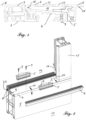
- Fig. 1
- einen Querschnitt durch eine herkömmliche Schwelle mit erfindungsgemäßer Zusatzvorrichtung;
- Fig. 2
- eine teilweise geschnittene Außenansicht des Türrahmens bei der Montage der Lageradapter und des äußeren Abdeckprofils;
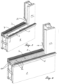
- Fig. 3
- eine erfindungsgemäße Tür von der Außenseite im geschlossenen Zustand;
- Fig. 4
- eine geschlossene Tür gemäß
Fig. 3 im Querschnitt; - Fig. 5
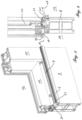
- eine teilweise geschnittene Außenansicht des Türrahmens bei der Montage des Schwellenrosts;
- Fig. 6
- eine teilweise geschnittene Außenansicht des Türrahmens mit aufgelegtem Schwellenrost;
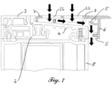
- Fig. 7
- einen Querschnitt durch die Schwelle mit Andeutung des Wasserführung.
- Bei dem nachfolgend näher beschriebenen Ausführungsbeispiel der Erfindung wird eine handelsübliche wärmegedämmte, aus der
WO 2015/011092 A1 bekannte Standard-Schwelle 1, bestehend aus einem aus Kunststoff extrudierten Grundkörper 2, einem ebenfalls aus Kunststoff extrudierten Abdeckprofil 3, auch Schwellendeckel genannt, sowie einem im Winkel schräg zur Gebäudeaußenseite 13 abfallenden, aus Aluminium stranggepressten Schwellen-Wetterschenkel 4 eingesetzt. An der gebäudeinnenseitigen (inFig. 1 linken) Seite weist der Schwellen-Wetterschenkel 4 einen Wirbelkanal 18 als Stufe 23 auf, der ohne die erfindungsgemäße Zusatzvorrichtung eine gewisse Barriere darstellen würde. Unterhalb der Standard-Schwelle 1 ist ein Bodeneinstandsprofil 8 zu erkennen (Fig. 2 ), das auf dem eigentlichen Baukörper, beispielsweise einer Betonplatte, aufliegt. - Die erfindungsgemäße Zusatzvorrichtung gemäß dem dargestellten Ausführungsbeispiel umfasst zunächst mehrere Lageradapter 5, die - wie in
Fig. 2 dargestellt - im Abstand von etwa 50-100 mm zueinander auf der gebäudeaußenseitigen Kante des Schwellen-Wetterschenkels 4 mittels der Schrauben 9 montiert werden. Zwischen je 2 dieser Lageradapter 5 kann daher Regenwasser, das in den Wasserablaufkanal 19 eingedrungen ist, in Richtung der Pfeile 20 abfließen. Die Wasserführung wird inFig. 7 nochmals verdeutlicht. - Gebäudeaußenseitig wird das äußere Abdeckprofil 6, das sich über die gesamte Längserstreckung des Schwellen-Wetterschenkels 4 erstreckt, auf die Lageradapter 5 aufgerastet. Die Oberseite dieses äußeren Abdeckprofils 6 verläuft in der gleichen Ebene "E" (
Fig. 4 ) wie die Oberseite des Abdeckprofils 3 auf der Gebäudeinnenseite 14 der thermisch getrennten Standard-Schwelle 1. Sowohl das äußere Abdeckprofil 6 als auch das innere Abdeckprofil 3 weisen eine geriffelte Struktur zur Erhöhung der Rutschsicherheit auf. - Wie in
Fig. 5 und 6 dargestellt, wird der Schwellenrost 7 auf den Wetterschenkel 11 und gebäudeaußenseitig auf die Lageradapter 5 aufgelegt. Hierzu weist das Schwellenrost gebäudeinnenseitig eine Abkantung auf (s.Fig. 4 im Schnitt), so dass der Schwellenrost ebenfalls bündig mit seiner Oberseite in derselben Ebene "E" verläuft, die durch die Oberseiten des inneren Abdeckprofils 3 und des äußeren Abdeckprofils 6 gebildet wird (Fig. 4 ). - Insbesondere anhand der Querschnittsdarstellung in
Fig. 1 wird deutlich, dass der zwischen dem Schwellenrost 7 und dem schräg nach außen geneigten Schwellen-Wetterschenkel 4 gebildete Raum einen Wasserablaufkanal 19 bildet. - Im dargestellten Ausführungsbeispiel besteht der Schwellenrost 7 aus Edelstahl und weist zwei Reihen mit als Langlöcher ausgestalteten Durchbrechungen 22 auf. Zwischen den beiden Reihen von Durchbrechungen 22 wird ein in Längsrichtung der Schwellenerstreckung verlaufender schmaler Steg gebildet, auf dem bei geschlossener Tür die sich ebenfalls über die gesamte Erstreckung der Schwelle 1 verlaufende Schlauchdichtungen 21 aufliegt. Hierdurch wird der Schwellenrost 7 in einen gebäudeinnenseitigen und einen gebäudeaußenseitigen Bereich unterteilt, so dass Regenwasser, das beispielsweise durch böigen Wind von der Gebäudeaußenseite 13 auf die Schwellenkonstruktion gedrückt wird, zum größten Teil bereits im Bereich der gebäudeaußenseitigen Reihe von Durchbrechungen 22 in den sich zwischen dem Schwellenrost 7 und dem Schwellen-Wetterschenkel 4 erstreckenden Wasserablaufkanal 19 abgeleitet wird. Soweit noch einige Tropfen des Regenwassers die äußere Schlauchdichtung 21 überwinden, werden sie zuverlässig in der gebäudeinnenseitigen zweiten Reihe von Durchbrechungen 22 in diesem Wasserablaufkanal 19 abgeleitet.
- Zusätzlich werden eine weitere Schlauchdichtung etwa im Übergangsbereich zwischen dem Schwellen-Wetterschenkel 4 und dem Abdeckprofil 3 sowie rauminnenseitig eine innere Anschlagdichtung 12 eingesetzt (s.
Fig. 4 ). Seitlich wird die Abdichtung durch eine an sich bekannte Windstopp-Dichtung 16 (Fig. 5 und 6 ) vervollständigt. - Wie in
Fig. 4 dargestellt, verläuft bei dem dargestellten Ausführungsbeispiel das Bodenniveau 17 auf der Gebäudeaußenseite 13 und der Gebäudeinnenseite 14 annähernd auf der gleichen, durch das innere Abdeckprofil 3, das äußere Abdeckprofil 6 sowie den Schwellenrost 7 gebildeten Ebene "E". Soweit auf eine innere Anschlagdichtung 12 verzichtet wird, kann auch ein absolut ebener Einbau erreicht werden. - Wie in
Fig. 3 und 4 dargestellt, ist am unteren waagerechten Holm des Türflügels 10 an dessen Außenseite ein Wetterschenkel 11 vorgesehen, der bei geschlossener Tür den Schwellenrost 7 weit gehend überdeckt, so dass Laub und Schnee die Durchbrechungen 22 des Schwellenrosts 7 nicht so leicht verstopfen kann. - Die vorgeschlagene Kombination aus Standard-Schwelle 1 und der Zusatzvorrichtung erlaubt die Herstellung einer sog. Null-Schwelle mit hervorragender Schlagregendichtigkeit. Da die Schwelle 1 auch ohne die Zusatzvorrichtung als Standard-Schwelle eingesetzt werden kann, verringert sich der Herstellungs- und Lageraufwand erheblich.
-
- 1
- thermisch getrennte Standard-Schwelle
- 2
- Grundkörper
- 3
- (inneres) Abdeckprofil (Schwellendeckel)
- 4
- Schwellen-Wetterschenkel
- 5
- Lageradapter
- 6
- äußeres Abdeckprofil
- 7
- Schwellenrost
- 8
- Bodeneinstandsprofil
- 9
- Schrauben
- 10
- Türflügel
- 11
- Wetterschenkel (Türflügel)
- 12
- innere Anschlagdichtung
- 13
- Gebäudeaußenseite
- 14
- Gebäudeinnenseite
- 15
- Blendrahmen/Pfosten
- 16
- Windstopp-Dichtung
- 17
- Bodenniveau/Bodenoberkante
- 18
- Wirbelkanal
- 19
- Wasserablaufkanal
- 20
- Pfeil
- 21
- Dichtung
- 22
- Durchbrechungen
- 23
- Stufe
Claims (5)
- Schwelle (1) mit Zusatzvorrichtung zur Verringerung der Barrierewirkung der Schwelle (1), wobei die Schwelle (1)- gebäudeinnenseitig ein insbesondere horizontal verlaufendes Abdeckprofil (3) und- gebäudeaußenseitig einen zum Gebäudeäußeren (13) geneigten und/oder abfallenden Schwellen-Wetterschenkel (4) umfasst,- wobei zwischen dem Schwellen-Wetterschenkel (4) und dem Abdeckprofil (3) eine Stufe (23) gebildet wird,wobei die Zusatzvorrichtung- ein Schwellenrost (7) sowie- Mittel zur beabstandeten Befestigung des Schwellenrosts (7) über dem Schwellen-Wetterschenkel (4) umfasst,so dass der Schwellenrost (7) im montierten Zustand- mit seiner Oberseite wenigstens weitgehend in der Ebene des gebäudeinnenseitigen Abdeckprofils (3) verläuft und- zwischen dem Schwellenrost (7) und dem Schwellen-Wetterschenkel (4) ein Wasserablaufkanal (19) gebildet wird,dadurch gekennzeichnet, dass die Zusatzvorrichtung ein gebäudeaußenseitig in Längserstreckung der Schwelle (1) verlaufendes äußeres Abdeckprofil (6) umfasst, das im montierten Zustand mit seiner Oberfläche in der gleichen Ebene verläuft wie das gebäudeinnenseitige Abdeckprofil (3) und der Schwellenrost (7), wobei als Mittel zur beabstandeten Befestigung des Schwellenrosts (7) über dem Schwellen-Wetterschenkel (4) mehrere in Längserstreckung der Schwelle (1) zueinander beabstandet angeordnete Lageradapter (5) eingesetzt werden, so dass zwischen je zwei Lageradaptern (5) Entwässerungsschlitze vom Wasserablaufkanal (19) zur Gebäudeaußenseite (13) gebildet werden.
- Schwelle (1) mit Zusatzvorrichtung nach Anspruch 1, dadurch gekennzeichnet, dass die zwischen dem Schwellen-Wetterschenkel (4) und dem Abdeckprofil (3) angeordnete Stufe (23) als Wirbelkanal (18) ausgebildet ist.
- Tür mit einer Schwelle (1) und einer Zusatzvorrichtung zur Verringerung der Barrierewirkung nach einem der Ansprüche 1 oder 2, dadurch gekennzeichnet, dass die Tür einen Türflügel (10) mit einer der Schwelle (1) zugewandten Unterseite umfasst, wobei die der Schwelle (1) zugewandten Unterseite mehrere parallel zueinander verlaufende Dichtungen aufweist.
- Tür nach Anspruch 3, dadurch gekennzeichnet, dass wenigstens eine der Dichtungen an der Unterseite des Türflügels (10) im geschlossenen Zustand der Tür auf dem Schwellenrost (7) aufliegt.
- Tür nach Anspruch 3 oder 4, dadurch gekennzeichnet, dass an dem Türflügel (10) gebäudeaußenseitig ein Wetterschenkel (11) befestigt ist, der bei geschlossener Tür den Schwellenrost (7) wenigstens teilweise überdeckt.
Applications Claiming Priority (1)
| Application Number | Priority Date | Filing Date | Title |
|---|---|---|---|
| EP15180389.7A EP3130738A1 (de) | 2015-08-10 | 2015-08-10 | Zusatzvorrichtung zur verringerung der barrierewirkung einer schwelle |
Publications (3)
| Publication Number | Publication Date |
|---|---|
| EP3130739A1 EP3130739A1 (de) | 2017-02-15 |
| EP3130739B1 EP3130739B1 (de) | 2018-03-28 |
| EP3130739B2 true EP3130739B2 (de) | 2025-02-19 |
Family
ID=53794117
Family Applications (2)
| Application Number | Title | Priority Date | Filing Date |
|---|---|---|---|
| EP15180389.7A Withdrawn EP3130738A1 (de) | 2015-08-10 | 2015-08-10 | Zusatzvorrichtung zur verringerung der barrierewirkung einer schwelle |
| EP16183531.9A Active EP3130739B2 (de) | 2015-08-10 | 2016-08-10 | Schwelle mit zusatzvorrichtung zur verringerung der barrierewirkung |
Family Applications Before (1)
| Application Number | Title | Priority Date | Filing Date |
|---|---|---|---|
| EP15180389.7A Withdrawn EP3130738A1 (de) | 2015-08-10 | 2015-08-10 | Zusatzvorrichtung zur verringerung der barrierewirkung einer schwelle |
Country Status (2)
| Country | Link |
|---|---|
| EP (2) | EP3130738A1 (de) |
| ES (1) | ES2671328T3 (de) |
Families Citing this family (4)
| Publication number | Priority date | Publication date | Assignee | Title |
|---|---|---|---|---|
| DE102019113777B4 (de) | 2019-01-11 | 2022-08-04 | Akotherm Gmbh | Tür, insbesondere Außentür, für ein Gebäude |
| EP3680442A1 (de) | 2019-01-11 | 2020-07-15 | Akoterm GmbH | Tür, insbesondere aussentür, für ein gebäude |
| DE102022117326A1 (de) * | 2022-07-12 | 2024-01-18 | Salamander Industrie-Produkte Gmbh | Wetterschenkel für Kunststoff-Extrusionsflügelprofile |
| EP4534789A1 (de) * | 2023-10-06 | 2025-04-09 | Gretsch-Unitas GmbH Baubeschläge | Gebäudeabschluss |
Citations (7)
| Publication number | Priority date | Publication date | Assignee | Title |
|---|---|---|---|---|
| JPH08105272A (ja) † | 1994-10-06 | 1996-04-23 | Sekisui Chem Co Ltd | 浴室の出入口構造 |
| US5687508A (en) † | 1995-10-30 | 1997-11-18 | Ykk Corporation Of America | Water resistant door assembly |
| JPH102166A (ja) † | 1996-06-18 | 1998-01-06 | Howa Mach Ltd | 出入口サッシの下枠構造 |
| DE20306546U1 (de) † | 2002-04-25 | 2003-09-04 | Frey Inge | Türdichtungsschwelle |
| DE102006007742A1 (de) † | 2006-01-13 | 2007-07-19 | Inge Frey | Bodenschwelle |
| EP2327854A2 (de) † | 2009-11-30 | 2011-06-01 | Inge Frey | Bodenschwelle sowie Verbreiterungs- und/oder Dämmsystem |
| DE202014102797U1 (de) † | 2014-06-17 | 2015-06-18 | Grundmeier Kg | Türschwellensystem für eine Haustür, eine Ladentür oder dergleichen |
Family Cites Families (5)
| Publication number | Priority date | Publication date | Assignee | Title |
|---|---|---|---|---|
| EP1932997A3 (de) | 2006-12-11 | 2011-01-19 | SYLID Systemlogistik und Industriedienstleistung GmbH | Oberer Abschluss einer Schwelle Abschluss-System sowie Schwelle |
| NL2005360C2 (nl) * | 2010-09-16 | 2012-03-19 | Isostone B V | Dorpel met afwatering. |
| DE202012001124U1 (de) | 2012-02-06 | 2012-05-09 | Claudia Rager-Frey | Zusatzelement zum Anordnen an einer Bodenschwelle |
| FR3003595B1 (fr) * | 2013-03-25 | 2015-05-15 | Weser | Seuil de porte prefabrique a acces facilite |
| DE202013103308U1 (de) | 2013-07-23 | 2014-09-24 | Profine Gmbh | System mit Pfostenprofil, Schwelle und Schwellenhalter |
-
2015
- 2015-08-10 EP EP15180389.7A patent/EP3130738A1/de not_active Withdrawn
-
2016
- 2016-08-10 EP EP16183531.9A patent/EP3130739B2/de active Active
- 2016-08-10 ES ES16183531.9T patent/ES2671328T3/es active Active
Patent Citations (7)
| Publication number | Priority date | Publication date | Assignee | Title |
|---|---|---|---|---|
| JPH08105272A (ja) † | 1994-10-06 | 1996-04-23 | Sekisui Chem Co Ltd | 浴室の出入口構造 |
| US5687508A (en) † | 1995-10-30 | 1997-11-18 | Ykk Corporation Of America | Water resistant door assembly |
| JPH102166A (ja) † | 1996-06-18 | 1998-01-06 | Howa Mach Ltd | 出入口サッシの下枠構造 |
| DE20306546U1 (de) † | 2002-04-25 | 2003-09-04 | Frey Inge | Türdichtungsschwelle |
| DE102006007742A1 (de) † | 2006-01-13 | 2007-07-19 | Inge Frey | Bodenschwelle |
| EP2327854A2 (de) † | 2009-11-30 | 2011-06-01 | Inge Frey | Bodenschwelle sowie Verbreiterungs- und/oder Dämmsystem |
| DE202014102797U1 (de) † | 2014-06-17 | 2015-06-18 | Grundmeier Kg | Türschwellensystem für eine Haustür, eine Ladentür oder dergleichen |
Also Published As
| Publication number | Publication date |
|---|---|
| EP3130739B1 (de) | 2018-03-28 |
| EP3130739A1 (de) | 2017-02-15 |
| EP3130738A1 (de) | 2017-02-15 |
| ES2671328T3 (es) | 2018-06-06 |
Similar Documents
| Publication | Publication Date | Title |
|---|---|---|
| EP2957702B1 (de) | Türschwellensystem für eine haustür, eine ladentür oder dergleichen | |
| EP3130739B2 (de) | Schwelle mit zusatzvorrichtung zur verringerung der barrierewirkung | |
| EP3043017B2 (de) | Drainagesystem für tür- und fensterelemente | |
| AT15735U1 (de) | Entwässerungssystem | |
| EP2357307A2 (de) | Sektionaltor | |
| DE202022101904U1 (de) | Entwässerungsvorrichtung für eine bauseitige Montage und Entwässerungssystem | |
| DE202015104176U1 (de) | Zusatzvorrichtung zur Verringerung der Barrierewirkung einer Schwelle | |
| DE202009017870U1 (de) | Rollladen-Fenster-Kombielement | |
| DE102023124723A1 (de) | Nullschwelle für eine Tür | |
| EP1251234B1 (de) | Türdichtung | |
| DE102016007242B4 (de) | Vorrichtung zum Abdecken des äußeren Bereichs der unteren Begrenzung einer Gebäudeöffnung | |
| DE69613744T2 (de) | Schutzvorrichtung zum Verhindern des Eindringens von Wasser in eine Wand und zum Verbessern des Abführens von Wasser aus einer Wand | |
| EP3299568B1 (de) | Dachfenster | |
| DE29618101U1 (de) | Vorrichtung zum Bilden eines unteren Türabschlusses | |
| EP2514905A2 (de) | Fensterrahmen für ein Verbundfenster oder eine Verbundfenstertür | |
| EP4442952B1 (de) | Tür- oder fensteranordnung mit wasserleitelement | |
| EP4357580B1 (de) | Wasserspeier zum entwässern einer rinne im bereich eines wandbildners eines gebäudes | |
| DE19850276B4 (de) | Laufschiene für eine Insektenschutztür | |
| EP3318710B1 (de) | Türschwellensystem | |
| DE19839455C1 (de) | Wasserableiteinrichtung für ein Fenster oder eine Tür mit einer Regenschutzschiene und einer Endkappe | |
| EP3045603B1 (de) | Pfosten-riegel-konstruktion | |
| EP4534789A1 (de) | Gebäudeabschluss | |
| DE19631492C2 (de) | Drainagewand | |
| DE10336910A1 (de) | Transformatorenstation | |
| DE202004006616U1 (de) | Lamellenfenster insbesondere für den Schägdachbereich |
Legal Events
| Date | Code | Title | Description |
|---|---|---|---|
| PUAI | Public reference made under article 153(3) epc to a published international application that has entered the european phase |
Free format text: ORIGINAL CODE: 0009012 |
|
| STAA | Information on the status of an ep patent application or granted ep patent |
Free format text: STATUS: THE APPLICATION HAS BEEN PUBLISHED |
|
| AK | Designated contracting states |
Kind code of ref document: A1 Designated state(s): AL AT BE BG CH CY CZ DE DK EE ES FI FR GB GR HR HU IE IS IT LI LT LU LV MC MK MT NL NO PL PT RO RS SE SI SK SM TR |
|
| AX | Request for extension of the european patent |
Extension state: BA ME |
|
| STAA | Information on the status of an ep patent application or granted ep patent |
Free format text: STATUS: REQUEST FOR EXAMINATION WAS MADE |
|
| 17P | Request for examination filed |
Effective date: 20170816 |
|
| RBV | Designated contracting states (corrected) |
Designated state(s): AL AT BE BG CH CY CZ DE DK EE ES FI FR GB GR HR HU IE IS IT LI LT LU LV MC MK MT NL NO PL PT RO RS SE SI SK SM TR |
|
| RIC1 | Information provided on ipc code assigned before grant |
Ipc: E06B 7/14 20060101ALI20170901BHEP Ipc: E06B 1/70 20060101ALI20170901BHEP Ipc: E06B 7/23 20060101AFI20170901BHEP |
|
| GRAP | Despatch of communication of intention to grant a patent |
Free format text: ORIGINAL CODE: EPIDOSNIGR1 |
|
| STAA | Information on the status of an ep patent application or granted ep patent |
Free format text: STATUS: GRANT OF PATENT IS INTENDED |
|
| INTG | Intention to grant announced |
Effective date: 20171023 |
|
| GRAS | Grant fee paid |
Free format text: ORIGINAL CODE: EPIDOSNIGR3 |
|
| GRAA | (expected) grant |
Free format text: ORIGINAL CODE: 0009210 |
|
| STAA | Information on the status of an ep patent application or granted ep patent |
Free format text: STATUS: THE PATENT HAS BEEN GRANTED |
|
| AK | Designated contracting states |
Kind code of ref document: B1 Designated state(s): AL AT BE BG CH CY CZ DE DK EE ES FI FR GB GR HR HU IE IS IT LI LT LU LV MC MK MT NL NO PL PT RO RS SE SI SK SM TR |
|
| REG | Reference to a national code |
Ref country code: GB Ref legal event code: FG4D Free format text: NOT ENGLISH |
|
| REG | Reference to a national code |
Ref country code: CH Ref legal event code: EP |
|
| REG | Reference to a national code |
Ref country code: AT Ref legal event code: REF Ref document number: 983610 Country of ref document: AT Kind code of ref document: T Effective date: 20180415 |
|
| REG | Reference to a national code |
Ref country code: IE Ref legal event code: FG4D Free format text: LANGUAGE OF EP DOCUMENT: GERMAN |
|
| REG | Reference to a national code |
Ref country code: DE Ref legal event code: R096 Ref document number: 502016000784 Country of ref document: DE |
|
| REG | Reference to a national code |
Ref country code: ES Ref legal event code: FG2A Ref document number: 2671328 Country of ref document: ES Kind code of ref document: T3 Effective date: 20180606 |
|
| REG | Reference to a national code |
Ref country code: CH Ref legal event code: NV Representative=s name: ISLER AND PEDRAZZINI AG, CH |
|
| REG | Reference to a national code |
Ref country code: NL Ref legal event code: FP |
|
| PG25 | Lapsed in a contracting state [announced via postgrant information from national office to epo] |
Ref country code: FI Free format text: LAPSE BECAUSE OF FAILURE TO SUBMIT A TRANSLATION OF THE DESCRIPTION OR TO PAY THE FEE WITHIN THE PRESCRIBED TIME-LIMIT Effective date: 20180328 Ref country code: HR Free format text: LAPSE BECAUSE OF FAILURE TO SUBMIT A TRANSLATION OF THE DESCRIPTION OR TO PAY THE FEE WITHIN THE PRESCRIBED TIME-LIMIT Effective date: 20180328 Ref country code: NO Free format text: LAPSE BECAUSE OF FAILURE TO SUBMIT A TRANSLATION OF THE DESCRIPTION OR TO PAY THE FEE WITHIN THE PRESCRIBED TIME-LIMIT Effective date: 20180628 Ref country code: LT Free format text: LAPSE BECAUSE OF FAILURE TO SUBMIT A TRANSLATION OF THE DESCRIPTION OR TO PAY THE FEE WITHIN THE PRESCRIBED TIME-LIMIT Effective date: 20180328 |
|
| REG | Reference to a national code |
Ref country code: LT Ref legal event code: MG4D |
|
| REG | Reference to a national code |
Ref country code: FR Ref legal event code: PLFP Year of fee payment: 3 |
|
| PG25 | Lapsed in a contracting state [announced via postgrant information from national office to epo] |
Ref country code: SE Free format text: LAPSE BECAUSE OF FAILURE TO SUBMIT A TRANSLATION OF THE DESCRIPTION OR TO PAY THE FEE WITHIN THE PRESCRIBED TIME-LIMIT Effective date: 20180328 Ref country code: LV Free format text: LAPSE BECAUSE OF FAILURE TO SUBMIT A TRANSLATION OF THE DESCRIPTION OR TO PAY THE FEE WITHIN THE PRESCRIBED TIME-LIMIT Effective date: 20180328 Ref country code: GR Free format text: LAPSE BECAUSE OF FAILURE TO SUBMIT A TRANSLATION OF THE DESCRIPTION OR TO PAY THE FEE WITHIN THE PRESCRIBED TIME-LIMIT Effective date: 20180629 Ref country code: BG Free format text: LAPSE BECAUSE OF FAILURE TO SUBMIT A TRANSLATION OF THE DESCRIPTION OR TO PAY THE FEE WITHIN THE PRESCRIBED TIME-LIMIT Effective date: 20180628 Ref country code: RS Free format text: LAPSE BECAUSE OF FAILURE TO SUBMIT A TRANSLATION OF THE DESCRIPTION OR TO PAY THE FEE WITHIN THE PRESCRIBED TIME-LIMIT Effective date: 20180328 |
|
| PG25 | Lapsed in a contracting state [announced via postgrant information from national office to epo] |
Ref country code: MT Free format text: LAPSE BECAUSE OF FAILURE TO SUBMIT A TRANSLATION OF THE DESCRIPTION OR TO PAY THE FEE WITHIN THE PRESCRIBED TIME-LIMIT Effective date: 20180328 |
|
| PG25 | Lapsed in a contracting state [announced via postgrant information from national office to epo] |
Ref country code: EE Free format text: LAPSE BECAUSE OF FAILURE TO SUBMIT A TRANSLATION OF THE DESCRIPTION OR TO PAY THE FEE WITHIN THE PRESCRIBED TIME-LIMIT Effective date: 20180328 Ref country code: AL Free format text: LAPSE BECAUSE OF FAILURE TO SUBMIT A TRANSLATION OF THE DESCRIPTION OR TO PAY THE FEE WITHIN THE PRESCRIBED TIME-LIMIT Effective date: 20180328 Ref country code: PL Free format text: LAPSE BECAUSE OF FAILURE TO SUBMIT A TRANSLATION OF THE DESCRIPTION OR TO PAY THE FEE WITHIN THE PRESCRIBED TIME-LIMIT Effective date: 20180328 Ref country code: RO Free format text: LAPSE BECAUSE OF FAILURE TO SUBMIT A TRANSLATION OF THE DESCRIPTION OR TO PAY THE FEE WITHIN THE PRESCRIBED TIME-LIMIT Effective date: 20180328 |
|
| PG25 | Lapsed in a contracting state [announced via postgrant information from national office to epo] |
Ref country code: CZ Free format text: LAPSE BECAUSE OF FAILURE TO SUBMIT A TRANSLATION OF THE DESCRIPTION OR TO PAY THE FEE WITHIN THE PRESCRIBED TIME-LIMIT Effective date: 20180328 Ref country code: SK Free format text: LAPSE BECAUSE OF FAILURE TO SUBMIT A TRANSLATION OF THE DESCRIPTION OR TO PAY THE FEE WITHIN THE PRESCRIBED TIME-LIMIT Effective date: 20180328 Ref country code: SM Free format text: LAPSE BECAUSE OF FAILURE TO SUBMIT A TRANSLATION OF THE DESCRIPTION OR TO PAY THE FEE WITHIN THE PRESCRIBED TIME-LIMIT Effective date: 20180328 |
|
| REG | Reference to a national code |
Ref country code: DE Ref legal event code: R026 Ref document number: 502016000784 Country of ref document: DE |
|
| PG25 | Lapsed in a contracting state [announced via postgrant information from national office to epo] |
Ref country code: PT Free format text: LAPSE BECAUSE OF FAILURE TO SUBMIT A TRANSLATION OF THE DESCRIPTION OR TO PAY THE FEE WITHIN THE PRESCRIBED TIME-LIMIT Effective date: 20180730 |
|
| PLBI | Opposition filed |
Free format text: ORIGINAL CODE: 0009260 |
|
| PLAX | Notice of opposition and request to file observation + time limit sent |
Free format text: ORIGINAL CODE: EPIDOSNOBS2 |
|
| PLAF | Information modified related to communication of a notice of opposition and request to file observations + time limit |
Free format text: ORIGINAL CODE: EPIDOSCOBS2 |
|
| PG25 | Lapsed in a contracting state [announced via postgrant information from national office to epo] |
Ref country code: DK Free format text: LAPSE BECAUSE OF FAILURE TO SUBMIT A TRANSLATION OF THE DESCRIPTION OR TO PAY THE FEE WITHIN THE PRESCRIBED TIME-LIMIT Effective date: 20180328 |
|
| 26 | Opposition filed |
Opponent name: GEZE GMBH Effective date: 20181221 |
|
| PG25 | Lapsed in a contracting state [announced via postgrant information from national office to epo] |
Ref country code: MC Free format text: LAPSE BECAUSE OF FAILURE TO SUBMIT A TRANSLATION OF THE DESCRIPTION OR TO PAY THE FEE WITHIN THE PRESCRIBED TIME-LIMIT Effective date: 20180328 |
|
| PG25 | Lapsed in a contracting state [announced via postgrant information from national office to epo] |
Ref country code: LU Free format text: LAPSE BECAUSE OF NON-PAYMENT OF DUE FEES Effective date: 20180810 |
|
| PG25 | Lapsed in a contracting state [announced via postgrant information from national office to epo] |
Ref country code: SI Free format text: LAPSE BECAUSE OF FAILURE TO SUBMIT A TRANSLATION OF THE DESCRIPTION OR TO PAY THE FEE WITHIN THE PRESCRIBED TIME-LIMIT Effective date: 20180328 |
|
| PLBB | Reply of patent proprietor to notice(s) of opposition received |
Free format text: ORIGINAL CODE: EPIDOSNOBS3 |
|
| REG | Reference to a national code |
Ref country code: DE Ref legal event code: R082 Ref document number: 502016000784 Country of ref document: DE Representative=s name: HOCKER, THOMAS GERHARD, DIPL.-ING., LL.M., DE |
|
| PG25 | Lapsed in a contracting state [announced via postgrant information from national office to epo] |
Ref country code: TR Free format text: LAPSE BECAUSE OF FAILURE TO SUBMIT A TRANSLATION OF THE DESCRIPTION OR TO PAY THE FEE WITHIN THE PRESCRIBED TIME-LIMIT Effective date: 20180328 |
|
| PG25 | Lapsed in a contracting state [announced via postgrant information from national office to epo] |
Ref country code: CY Free format text: LAPSE BECAUSE OF FAILURE TO SUBMIT A TRANSLATION OF THE DESCRIPTION OR TO PAY THE FEE WITHIN THE PRESCRIBED TIME-LIMIT Effective date: 20180328 Ref country code: HU Free format text: LAPSE BECAUSE OF FAILURE TO SUBMIT A TRANSLATION OF THE DESCRIPTION OR TO PAY THE FEE WITHIN THE PRESCRIBED TIME-LIMIT; INVALID AB INITIO Effective date: 20160810 Ref country code: MK Free format text: LAPSE BECAUSE OF NON-PAYMENT OF DUE FEES Effective date: 20180328 |
|
| PG25 | Lapsed in a contracting state [announced via postgrant information from national office to epo] |
Ref country code: IS Free format text: LAPSE BECAUSE OF FAILURE TO SUBMIT A TRANSLATION OF THE DESCRIPTION OR TO PAY THE FEE WITHIN THE PRESCRIBED TIME-LIMIT Effective date: 20180728 |
|
| APBM | Appeal reference recorded |
Free format text: ORIGINAL CODE: EPIDOSNREFNO |
|
| APBP | Date of receipt of notice of appeal recorded |
Free format text: ORIGINAL CODE: EPIDOSNNOA2O |
|
| APAH | Appeal reference modified |
Free format text: ORIGINAL CODE: EPIDOSCREFNO |
|
| RAP4 | Party data changed (patent owner data changed or rights of a patent transferred) |
Owner name: PROFINE GMBH |
|
| APBQ | Date of receipt of statement of grounds of appeal recorded |
Free format text: ORIGINAL CODE: EPIDOSNNOA3O |
|
| REG | Reference to a national code |
Ref country code: AT Ref legal event code: MM01 Ref document number: 983610 Country of ref document: AT Kind code of ref document: T Effective date: 20210810 |
|
| PG25 | Lapsed in a contracting state [announced via postgrant information from national office to epo] |
Ref country code: AT Free format text: LAPSE BECAUSE OF NON-PAYMENT OF DUE FEES Effective date: 20210810 |
|
| REG | Reference to a national code |
Ref country code: DE Ref legal event code: R081 Ref document number: 502016000784 Country of ref document: DE Owner name: PROFINE GMBH, DE Free format text: FORMER OWNER: PROFINE GMBH, 53840 TROISDORF, DE |
|
| RAP4 | Party data changed (patent owner data changed or rights of a patent transferred) |
Owner name: PROFINE GMBH |
|
| PGFP | Annual fee paid to national office [announced via postgrant information from national office to epo] |
Ref country code: ES Payment date: 20221025 Year of fee payment: 7 |
|
| APAH | Appeal reference modified |
Free format text: ORIGINAL CODE: EPIDOSCREFNO |
|
| PGFP | Annual fee paid to national office [announced via postgrant information from national office to epo] |
Ref country code: NL Payment date: 20230821 Year of fee payment: 8 |
|
| PGFP | Annual fee paid to national office [announced via postgrant information from national office to epo] |
Ref country code: IT Payment date: 20230825 Year of fee payment: 8 Ref country code: IE Payment date: 20230822 Year of fee payment: 8 Ref country code: GB Payment date: 20230822 Year of fee payment: 8 Ref country code: CH Payment date: 20230902 Year of fee payment: 8 |
|
| PGFP | Annual fee paid to national office [announced via postgrant information from national office to epo] |
Ref country code: BE Payment date: 20230821 Year of fee payment: 8 |
|
| APBU | Appeal procedure closed |
Free format text: ORIGINAL CODE: EPIDOSNNOA9O |
|
| REG | Reference to a national code |
Ref country code: ES Ref legal event code: FD2A Effective date: 20240930 |
|
| PGFP | Annual fee paid to national office [announced via postgrant information from national office to epo] |
Ref country code: FR Payment date: 20240829 Year of fee payment: 9 |
|
| PG25 | Lapsed in a contracting state [announced via postgrant information from national office to epo] |
Ref country code: ES Free format text: LAPSE BECAUSE OF NON-PAYMENT OF DUE FEES Effective date: 20230811 |
|
| PG25 | Lapsed in a contracting state [announced via postgrant information from national office to epo] |
Ref country code: ES Free format text: LAPSE BECAUSE OF NON-PAYMENT OF DUE FEES Effective date: 20230811 |
|
| PUAH | Patent maintained in amended form |
Free format text: ORIGINAL CODE: 0009272 |
|
| STAA | Information on the status of an ep patent application or granted ep patent |
Free format text: STATUS: PATENT MAINTAINED AS AMENDED |
|
| 27A | Patent maintained in amended form |
Effective date: 20250219 |
|
| AK | Designated contracting states |
Kind code of ref document: B2 Designated state(s): AL AT BE BG CH CY CZ DE DK EE ES FI FR GB GR HR HU IE IS IT LI LT LU LV MC MK MT NL NO PL PT RO RS SE SI SK SM TR |
|
| REG | Reference to a national code |
Ref country code: DE Ref legal event code: R102 Ref document number: 502016000784 Country of ref document: DE |
|
| REG | Reference to a national code |
Ref country code: CH Ref legal event code: PL |
|
| REG | Reference to a national code |
Ref country code: NL Ref legal event code: MM Effective date: 20240901 |
|
| GBPC | Gb: european patent ceased through non-payment of renewal fee |
Effective date: 20240810 |
|
| PG25 | Lapsed in a contracting state [announced via postgrant information from national office to epo] |
Ref country code: CH Free format text: LAPSE BECAUSE OF NON-PAYMENT OF DUE FEES Effective date: 20240831 |
|
| PG25 | Lapsed in a contracting state [announced via postgrant information from national office to epo] |
Ref country code: NL Free format text: LAPSE BECAUSE OF NON-PAYMENT OF DUE FEES Effective date: 20240901 |
|
| REG | Reference to a national code |
Ref country code: BE Ref legal event code: MM Effective date: 20240831 |
|
| PG25 | Lapsed in a contracting state [announced via postgrant information from national office to epo] |
Ref country code: GB Free format text: LAPSE BECAUSE OF NON-PAYMENT OF DUE FEES Effective date: 20240810 |
|
| PG25 | Lapsed in a contracting state [announced via postgrant information from national office to epo] |
Ref country code: BE Free format text: LAPSE BECAUSE OF NON-PAYMENT OF DUE FEES Effective date: 20240831 Ref country code: IT Free format text: LAPSE BECAUSE OF NON-PAYMENT OF DUE FEES Effective date: 20240810 |
|
| PG25 | Lapsed in a contracting state [announced via postgrant information from national office to epo] |
Ref country code: IE Free format text: LAPSE BECAUSE OF NON-PAYMENT OF DUE FEES Effective date: 20240810 |
|
| PGFP | Annual fee paid to national office [announced via postgrant information from national office to epo] |
Ref country code: DE Payment date: 20250820 Year of fee payment: 10 |