EP3119583B1 - Winkelverstellbare anpress- oder nipwalze - Google Patents
Winkelverstellbare anpress- oder nipwalze Download PDFInfo
- Publication number
- EP3119583B1 EP3119583B1 EP15704209.4A EP15704209A EP3119583B1 EP 3119583 B1 EP3119583 B1 EP 3119583B1 EP 15704209 A EP15704209 A EP 15704209A EP 3119583 B1 EP3119583 B1 EP 3119583B1
- Authority
- EP
- European Patent Office
- Prior art keywords
- pressure
- stop
- roller
- nip roller
- angle
- Prior art date
- Legal status (The legal status is an assumption and is not a legal conclusion. Google has not performed a legal analysis and makes no representation as to the accuracy of the status listed.)
- Active
Links
- 238000003825 pressing Methods 0.000 title description 8
- 238000000034 method Methods 0.000 claims description 124
- 230000008569 process Effects 0.000 claims description 124
- 239000000463 material Substances 0.000 claims description 31
- 230000007246 mechanism Effects 0.000 claims description 9
- 238000006073 displacement reaction Methods 0.000 claims description 8
- 230000000694 effects Effects 0.000 claims description 2
- 230000005484 gravity Effects 0.000 claims description 2
- 230000004913 activation Effects 0.000 claims 4
- 238000004519 manufacturing process Methods 0.000 description 9
- 239000000243 solution Substances 0.000 description 9
- 238000000576 coating method Methods 0.000 description 7
- 239000011248 coating agent Substances 0.000 description 6
- 230000004323 axial length Effects 0.000 description 4
- 230000008901 benefit Effects 0.000 description 3
- 229920001169 thermoplastic Polymers 0.000 description 3
- 239000004416 thermosoftening plastic Substances 0.000 description 3
- 239000004744 fabric Substances 0.000 description 2
- 239000011888 foil Substances 0.000 description 2
- 238000009434 installation Methods 0.000 description 2
- 239000002184 metal Substances 0.000 description 2
- 239000002985 plastic film Substances 0.000 description 2
- 229920006255 plastic film Polymers 0.000 description 2
- BYHQTRFJOGIQAO-GOSISDBHSA-N 3-(4-bromophenyl)-8-[(2R)-2-hydroxypropyl]-1-[(3-methoxyphenyl)methyl]-1,3,8-triazaspiro[4.5]decan-2-one Chemical compound C[C@H](CN1CCC2(CC1)CN(C(=O)N2CC3=CC(=CC=C3)OC)C4=CC=C(C=C4)Br)O BYHQTRFJOGIQAO-GOSISDBHSA-N 0.000 description 1
- 230000009471 action Effects 0.000 description 1
- 230000008859 change Effects 0.000 description 1
- 238000010276 construction Methods 0.000 description 1
- 238000001816 cooling Methods 0.000 description 1
- 238000005520 cutting process Methods 0.000 description 1
- 230000007547 defect Effects 0.000 description 1
- 238000001514 detection method Methods 0.000 description 1
- 239000007888 film coating Substances 0.000 description 1
- 238000009501 film coating Methods 0.000 description 1
- 239000003517 fume Substances 0.000 description 1
- 239000008187 granular material Substances 0.000 description 1
- 238000003780 insertion Methods 0.000 description 1
- 230000037431 insertion Effects 0.000 description 1
- 239000000155 melt Substances 0.000 description 1
- 230000003287 optical effect Effects 0.000 description 1
- 239000004033 plastic Substances 0.000 description 1
- 229920003023 plastic Polymers 0.000 description 1
- 229920000642 polymer Polymers 0.000 description 1
- 238000000926 separation method Methods 0.000 description 1
- 230000007480 spreading Effects 0.000 description 1
- 238000003892 spreading Methods 0.000 description 1
Images


Classifications
-
- B—PERFORMING OPERATIONS; TRANSPORTING
- B29—WORKING OF PLASTICS; WORKING OF SUBSTANCES IN A PLASTIC STATE IN GENERAL
- B29C—SHAPING OR JOINING OF PLASTICS; SHAPING OF MATERIAL IN A PLASTIC STATE, NOT OTHERWISE PROVIDED FOR; AFTER-TREATMENT OF THE SHAPED PRODUCTS, e.g. REPAIRING
- B29C55/00—Shaping by stretching, e.g. drawing through a die; Apparatus therefor
- B29C55/02—Shaping by stretching, e.g. drawing through a die; Apparatus therefor of plates or sheets
- B29C55/04—Shaping by stretching, e.g. drawing through a die; Apparatus therefor of plates or sheets uniaxial, e.g. oblique
- B29C55/06—Shaping by stretching, e.g. drawing through a die; Apparatus therefor of plates or sheets uniaxial, e.g. oblique parallel with the direction of feed
-
- B—PERFORMING OPERATIONS; TRANSPORTING
- B29—WORKING OF PLASTICS; WORKING OF SUBSTANCES IN A PLASTIC STATE IN GENERAL
- B29C—SHAPING OR JOINING OF PLASTICS; SHAPING OF MATERIAL IN A PLASTIC STATE, NOT OTHERWISE PROVIDED FOR; AFTER-TREATMENT OF THE SHAPED PRODUCTS, e.g. REPAIRING
- B29C33/00—Moulds or cores; Details thereof or accessories therefor
- B29C33/34—Moulds or cores; Details thereof or accessories therefor movable, e.g. to or from the moulding station
-
- B—PERFORMING OPERATIONS; TRANSPORTING
- B29—WORKING OF PLASTICS; WORKING OF SUBSTANCES IN A PLASTIC STATE IN GENERAL
- B29C—SHAPING OR JOINING OF PLASTICS; SHAPING OF MATERIAL IN A PLASTIC STATE, NOT OTHERWISE PROVIDED FOR; AFTER-TREATMENT OF THE SHAPED PRODUCTS, e.g. REPAIRING
- B29C43/00—Compression moulding, i.e. applying external pressure to flow the moulding material; Apparatus therefor
- B29C43/22—Compression moulding, i.e. applying external pressure to flow the moulding material; Apparatus therefor of articles of indefinite length
- B29C43/24—Calendering
- B29C43/245—Adjusting calender parameters, e.g. bank quantity
-
- B—PERFORMING OPERATIONS; TRANSPORTING
- B29—WORKING OF PLASTICS; WORKING OF SUBSTANCES IN A PLASTIC STATE IN GENERAL
- B29C—SHAPING OR JOINING OF PLASTICS; SHAPING OF MATERIAL IN A PLASTIC STATE, NOT OTHERWISE PROVIDED FOR; AFTER-TREATMENT OF THE SHAPED PRODUCTS, e.g. REPAIRING
- B29C55/00—Shaping by stretching, e.g. drawing through a die; Apparatus therefor
- B29C55/02—Shaping by stretching, e.g. drawing through a die; Apparatus therefor of plates or sheets
- B29C55/18—Shaping by stretching, e.g. drawing through a die; Apparatus therefor of plates or sheets by squeezing between surfaces, e.g. rollers
-
- B—PERFORMING OPERATIONS; TRANSPORTING
- B29—WORKING OF PLASTICS; WORKING OF SUBSTANCES IN A PLASTIC STATE IN GENERAL
- B29C—SHAPING OR JOINING OF PLASTICS; SHAPING OF MATERIAL IN A PLASTIC STATE, NOT OTHERWISE PROVIDED FOR; AFTER-TREATMENT OF THE SHAPED PRODUCTS, e.g. REPAIRING
- B29C43/00—Compression moulding, i.e. applying external pressure to flow the moulding material; Apparatus therefor
- B29C43/22—Compression moulding, i.e. applying external pressure to flow the moulding material; Apparatus therefor of articles of indefinite length
- B29C43/24—Calendering
-
- B—PERFORMING OPERATIONS; TRANSPORTING
- B29—WORKING OF PLASTICS; WORKING OF SUBSTANCES IN A PLASTIC STATE IN GENERAL
- B29C—SHAPING OR JOINING OF PLASTICS; SHAPING OF MATERIAL IN A PLASTIC STATE, NOT OTHERWISE PROVIDED FOR; AFTER-TREATMENT OF THE SHAPED PRODUCTS, e.g. REPAIRING
- B29C43/00—Compression moulding, i.e. applying external pressure to flow the moulding material; Apparatus therefor
- B29C43/32—Component parts, details or accessories; Auxiliary operations
- B29C43/44—Compression means for making articles of indefinite length
- B29C43/46—Rollers
-
- B—PERFORMING OPERATIONS; TRANSPORTING
- B29—WORKING OF PLASTICS; WORKING OF SUBSTANCES IN A PLASTIC STATE IN GENERAL
- B29C—SHAPING OR JOINING OF PLASTICS; SHAPING OF MATERIAL IN A PLASTIC STATE, NOT OTHERWISE PROVIDED FOR; AFTER-TREATMENT OF THE SHAPED PRODUCTS, e.g. REPAIRING
- B29C63/00—Lining or sheathing, i.e. applying preformed layers or sheathings of plastics; Apparatus therefor
- B29C63/02—Lining or sheathing, i.e. applying preformed layers or sheathings of plastics; Apparatus therefor using sheet or web-like material
-
- B—PERFORMING OPERATIONS; TRANSPORTING
- B29—WORKING OF PLASTICS; WORKING OF SUBSTANCES IN A PLASTIC STATE IN GENERAL
- B29K—INDEXING SCHEME ASSOCIATED WITH SUBCLASSES B29B, B29C OR B29D, RELATING TO MOULDING MATERIALS OR TO MATERIALS FOR MOULDS, REINFORCEMENTS, FILLERS OR PREFORMED PARTS, e.g. INSERTS
- B29K2101/00—Use of unspecified macromolecular compounds as moulding material
- B29K2101/12—Thermoplastic materials
-
- B—PERFORMING OPERATIONS; TRANSPORTING
- B29—WORKING OF PLASTICS; WORKING OF SUBSTANCES IN A PLASTIC STATE IN GENERAL
- B29L—INDEXING SCHEME ASSOCIATED WITH SUBCLASS B29C, RELATING TO PARTICULAR ARTICLES
- B29L2007/00—Flat articles, e.g. films or sheets
- B29L2007/008—Wide strips, e.g. films, webs
Definitions
- the invention relates to an angle-adjustable pressure or Nipwalze according to the preamble of claim 1.
- Such angle-adjustable pressure or Nipwalzen can be used in different technical fields. They have significance, for example, in the production of films in longitudinal stretching machines, a draw-off machine, a coating installation and the like.
- such an angle-adjustable pressure roller can be used everywhere, where film-like material webs are moved across rollers, while the moving material web is to be pressed using a so-called nip roll or a nip roll on the outer surface of the process roller.
- the pressure rollers or nip rollers in question can, for example, not only have significance in the production of plastic films but can also be used in the metal or paper industry. There are no restrictions in this respect.
- thermoplastic films In the production of thermoplastic films, a polymer granulate is first melted in an extruder, and then fed to a flat-slit die. The melt is cooled on a cooling roller and is then fed to a so-called. Lssensrecktechnik. There, the pre-film is heated at an entry velocity v1 in a series of preheat rolls, and then stretched in a so-called stretching unit in the longitudinal direction or machine direction MD with a discharge speed v2> v1. After the longitudinal stretching (that is to say a stretching in the machine MDO direction), the fabric web is stretched in the width direction (ie in a transverse direction TDO transversely to the machine longitudinal direction). Before and / or after the spreading (TDO), an optional coating system can be provided. The web is withdrawn from the wide or transverse stretching (TDO) or the coating system and wound up.
- TDO wide or transverse stretching
- Such or several such axially parallel successively arranged processing rollers for processing or transporting thermoplastic films are rotatably mounted in bearing plates. These rollers work with one or more pressure rollers or Nipwalzen together, which are rotatably mounted in a pivotally mounted on both sides of the roller holder, and wherein a piston-cylinder unit applies the pressure roller to the input-side roller or lifted from this.
- a corresponding longitudinal stretching machine, in particular for thermoplastic films with several axially parallel successive stretching rollers, which is associated with a rotatably mounted pressure roller is, for example, from EP 0 677 372 B1 known.
- the pressure roller is held pivotably via a pair of supports, wherein the axis of rotation of the pair of supports is mounted about a parallel to the center axis of the input and / or output side stretching roller shaft.
- the pivotally mounted pair of supports can be locked together with the pressure roller on a fixable about the center axis of the stretching roller rotation angle range according to a line and in at least a first and a second end position.
- the pressure roller according to the EP 0 677 372 B1 rotatably mounted so that it can be adjusted around a process roller around.
- the pivot mechanism of the pressure roller including the Zustellzylinders is rotatably mounted on the Achshalterung the process roller. The pressure roller can be lifted off from the process roller via the feed cylinder.
- the tangential starting point is determined by the web and can only be moved in one direction.
- the pressure roller can be moved only in the direction of the already adjacent surface of the web.
- a calender which includes a process roller referred to there as an intermediate roll, which cooperates with a plurality of nip rolls.
- the nip rollers are mounted approximately centrally on a lever, said adjusting lever is rotatably mounted at its one end to the calender stand. At the other end of the lever then sets a cylindrical relief device to adjust the adjustment forces of the press roll, with which this rests against the process roller.
- the threading of the goods or material web should be facilitated.
- Compressive rolls as well as so-called nip rolls are auxiliary devices, e.g. cooperate with stretching rollers in a film-length stretching machine in order to press or press the film onto these rollers.
- nip rolls In fume cupping and wrapping systems, they ensure that a web can be transported out of the stretching machine and wound up.
- coating plants they provide u.a. for ensuring the flatness.
- pressure rollers which as a rule have a roller length which is comparable to the axial length of the process roller.
- so-called Nipwalzen can be used, which occupy a certain position with respect to the process roller in the inlet and outlet of the web and usually have only a shorter axial length than the actual process roller and thereby often positioned only in the area of the process roller end portions and therefore only effective there.
- the solution according to the invention is characterized by a combination of different features.
- the angle-adjustable contact pressure and / or nip roll is pivotable about an axis which is arranged offset to the actual axis of the process roll.
- the contact pressure and / or nip roll arranged so far radially offset from the actual process roll, that a sufficient distance space between the holding and adjusting the nip roll and the nip and / or nip roll itself and the actual process roller can be adjusted. This greatly facilitates the threading of the material to be passed through the system web.
- the invention is characterized in a preferred embodiment in that different stop-limited angular positions for the pressure and / or Nipwalze can be adjusted, in which then the pressure and / or Nipwalze can be adjusted to the roll circumference of the process roll (see sandwiching the web of material passed therebetween).
- nip roll Depending on which function the nip roll has to fulfill, it must assume a certain position in relation to the process roll at the inlet and / or outlet of the fabric web.
- the pressure roller must place directly on the tangential inlet of the film on the stretching roller.
- the scratch resistance to coated or coated webs can be significantly improved if the position of the lay line can be adjusted by means of a defect detection system during operation and thus optimized.
- the transferable stretching forces or the looping friction can be increased if the pressure roller acts as close as possible to the inlet of the tangential inlet point of the film on the stretching roller.
- a pressure roller on the stretching roller can also act here a pressure roller on the stretching roller. Without a corresponding pressure roller, depending on the coefficient of friction between the film and the stretching roller, a "film entry" arising during stretching would continue from the edge regions of the roller over its surface in the direction of the roller center.
- a running of the web along the transverse direction (TDO) can be prevented or minimized in all rolls by a contact pressure and / or nip roll according to the invention.
- the pressing direction of the pressing and / or nip roll is not equal to the feed direction of this roller.
- the position of the pressure roller can also be adjusted during operation relative to the process roller. This provides important benefits, as it is necessary for some processes to continually optimize the position.
- the control mechanism is independent of the mechanics of the process roller.
- the invention provides significant advantages over conventional solutions, especially because the application point or the laying lines can be flexibly adapted to the processes of operation and / or production, wherein, above all, the threading or insertion of the goods or material web clearly is explained.
- both the position and the force introduction can be made via the pivot point and / or the stop surface, which is not possible in the generic solution.
- a process roller 2 is rotatably mounted in the region of its opposite end sides via bearings 2.1 in holding devices 1 provided there, for example in the form of a respective bearing plate.
- the holding devices 1, which are located on the opposite end faces of in FIG. 1 shown rollers, so the process roller 2 and the pressing and / or Nipwalzen 3, 4 connect, may be identical or at least substantially similar construction.
- the film F passes over the process roller.
- the adjusting mechanism 6 for the pressing or nip rollers 3, 4 is screwed to the holding device 1.
- the holding device 1 can be designed and fixed differently depending on the application.
- the process roller 2 extends over the respective working width AB of the web. If so-called Nipwalzen used instead of nip rollers 3, 4, then the roll width is not the entire AB, but Nipwalzen are used only in the edge regions of the web, and are therefore shorter.
- An adjusting device VE with associated adjustment mechanism 6 is a mirror image symmetrical to the so-called. Drive and operator site (ie on the right and left side of the figure according to FIG. 1 ).
- the adjusting device VE with the adjusting mechanism 6 includes adjusting slide 6.2 and linear guides 6.1, about which the pressing or Nipwalzen 3, 4 can be delivered by a power actuator 10 to the process roller 2 and subjected to force.
- the pressure or Nipwalzen 3, 4 exert on their associated roll shell 3 'and 4' a contact pressure on the roll shell 2 'of the process roll 2, wherein between the respective jacket 3', 4 'of the nip roll or the third , 4 and the roll shell 2 'of the process roller 2, the material web F is passed, act on the corresponding contact forces.
- the adjusting device provided for this purpose comprises VE a traversing VF, which is formed in the context of the invention as a linear or translationally adjustable traversing VF, and in addition an angle adjustment WE, via the different investment positions of the respective nip roll or nipwalze 3, 3 are adjustable relative to the process roller 2.
- the pressure rollers 3 and 4 are rotatably attached to the Achsstofflinien 3.5 and 4.5 to the adjusting levers 7.1 and 7.2.
- the lever arms of the two adjusting levers 7.1, 7.2 are rotatably mounted on pivot axis 8.1, 8.2.
- the pivot axis (s) are attached to provided Verstellschlitten 6.2.
- the angle adjustment device WE comprises a double-armed adjusting lever 7.1, 7.2.
- This adjusting lever 7.1, 7.2 is in each case via the pivoting adjustment WE via a pivot axis 8.1, 8.2 held pivotally on the traversing VF, wherein the pivot axis 8.1, 8.2 by means of the traversing VF along the feed direction ZR is movable.
- the respective stop pin 9.2 is firmly connected to the pivot lever 7.1 or 7.2.
- the stop surface 9.1 can be moved automatically or manually via provided actuators 11.
- actuators 11 all drives can be used in the prior art.
- a gear 11.1 can be switched in between.
- the stop adjustment consists of a holding plate 90.1, in which slots are 90.2, which serve as a guide for the adjustment 90.3.
- Display units 100.1 serve for further guidance of the adjustment units 90.3 and for optical display of the adjustment path, for which purpose a scale 100.2 is provided.
- the two adjusting levers 7.1 and 7.2 for adjusting the pressure roller 3 located farther to the left or to the left in FIGS. 1 and 2 or the pressure roller 4 lying farther to the right or to the right in each case about the mentioned pivot axis 8.1 between 8.2 are pivotable.
- the two adjusting levers 7.1 and 7.2 in each case in opposite or mutually away direction while slightly angularly aligned lever arms 7.1a and 7.1b and 7.2a and 7.2b.
- the respective pressure or Nipwalze 3, 4 is stored.
- lever arm 7.1b and 7.2b At the opposite and rather upwardly extending lever arm 7.1b and 7.2b is the respective mentioned and formed with the adjusting lever with pivotable stop or stop pin 9.2.
- the effective length of the respective Anpress- or Nipwalze supporting lever arm 7.1a and 7.2a (starting from the pivot axis 8.1 and 8.2 to the associated axis centerline 3.5 or 4.5 of the pressure roller 3, 4) is with LV in FIG. 2 characterized in that the effective length between the respective pivot axis 8.1 and 8.2 and the position of the stop pin 9.2 on the respective second lever arm 7.1b and 7.2b by the size LB in Figure 2 is characterized.
- both the position and the contact forces with an adjustable contact force of the force mechanism 10 are determined.
- both the position and the contact forces with an adjustable contact force of the force mechanism 10 are determined.
- the position and the force introduction direction of the pressure roller 3, 4 relative to the process roller 2 is determined.
- FIGS. 8.1 to 8.4 is to see how the investment line between the respective nip roll or nipwalze 3, 4 and the process roller 2 by different settings of the stop surface or the stop 9.1 is changeable. As a result, the contact pressure line is changed in its position along which a corresponding pressure is exerted on the roll shell 2 'of the process roll 2 via the roll shell 3', 4 'of the pressure or nip roll 3, 4.
- the contact pressure can be changed by the described structure.
- the pressing device can be mounted both on the arrival and expiration direction of the film, but also only in one direction.
- the settings of the tangential start-up line can be adjusted accordingly.
- the adjusting unit 90.3 for the stop surface 9.1 is adjusted by means of a spindle 90.4 with the stable drive 11 and the optional gear 11.1 (FIG. FIG. 4 ).
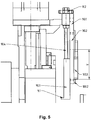
- FIG. 5 is a manual adjustment via a handwheel 11.2 shown.
- FIG. 6 shows the lever 7.1 with the stop pin 9.2 with removed holding plate 90.1 and the entire dismantled adjusting unit to illustrate the leverages. Only the “virtual" stop surface 9.1 is shown for clarity.
- the adjusting lever 7.1 or 7.2 can also be determined by the respective adjusting lever 7.1 or 7.2 is festschraubt there provided holes 70.1.
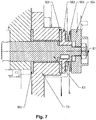
- FIG. 7 shows the section through the lever axis 8.1, on which the adjusting lever turns 7.1.
- the two brake discs 50.1 which are mounted on a centering disc 50.2 on the axis of rotation.
- Via a plate spring 50.3 and a pressure plate 50.4 the friction can be adjusted so that the respective adjusting lever 7.1 or 7.2 remains stationary in its last position.
- the two brake discs 50.1 are axially offset from each other, in the axial direction of the respective pivot axis 8.1 and 8.2.
- the brake discs 50.1 sit as perforated discs on a corresponding axle 8.3 of the respective pivot axis 8.1 and 8.2 forms.
- the two brake discs 50.1 in the axial direction to each other subjected to force, under sandwich-like intermediate recording of a corresponding portion of the adjusting lever 7.1 (or 7.2).
- FIGS. 8.1 to 8.4 show different examples each in an axial sectional view of a process roller 2, which can be brought on the inlet side of the process roller with a pressure roller 3 in contact is.
- the roll shell 3 'of the pressure roll 3 and the roll shell 2' touch the roll 2 along a parallel to the axial center line of the rollers contact line, the roll coats 2 'and 3' are not directly in contact, as between the two Walzenmänteln 2 ' and 3 ', as shown, of course, the material web or, for example, the plastic film film F is passed.
- An adjustment of the pressure roller 3 by means of the illustrated adjusting device VE which is a the pressure roller between an operating position and a parking position traversing VF (which in the embodiment shown consists of a translational adjustment enabling trajectory VF) and an angle adjustment WE for each Anpress- or Nipwalze 3 includes.
- the corresponding contact forces can be generated and adjusted.
- the pressure roller 3 is pressed against the roll rotation axis 2 '(ie the mantle or surface of the process roller 2) along a contact line parallel to the roll rotation axis via the force actuating unit 10, wherein between the roll shell (FIG. or the mantle or surface) of the pressure roller 3 and the mantle or surface of the process roller 2, the material web F along the arrow display 37 (ie between the two rollers) passed and is guided around the process roller in a Generalumschlingungswinkel.
- the pressure roller 3 is shown in its working or operating position, in which a through the axial center line of the pressure roller 3 and the process roller 2 guided straight line G with respect to a plane H occupies an angle ⁇ 1.
- This plane H is ultimately aligned perpendicular to the feed direction ZR of the track VF, which extends in this respect by the carriage arrangement by the adjusting device by means of the power actuator.
- a stop height h1 is also set, which is defined by the distance between the axis center line 2.5 of the process roller 2 and the position of the stop or the stop surface 9.1, ie in the direction parallel to the feed ZR, with the Winkelverstell worn WE, ie the lever arms 7.1 ( and optionally 7.2) pivotally holding pivot axis 8 (in this case with respect to the pressure roller 3, the pivot axis 8.1) is adjusted by the force application device.
- the pressure roller 3 can touch the material web F in the region in which the material web F on the mantle or surface after touching the mantle or surface 3 ' 2 'of the process roller 2 is applied, are pivoted in the illustration shown in the clockwise direction, and indeed so far, until the pivot lever 7.1 strikes with the attached stop pin 9.2 on the stop surface 9.1. A further pivoting in the clockwise direction is then not possible, so that by appropriate adjustment of the pneumatic cylinder (ie the power actuator 10) ultimately the contact forces can be defined.
- the delivery direction ZR is also shown, along which, upon actuation of the force actuating unit 10, the translationally acting adjustment part of the entire adjustment device VE (ie the so-called traversing unit VF) and thus the pressure roller 4 is moved.
- the pressure roller 3 according to their parking position Figure 8.2 be moved so far along the feed direction ZR until the outer surfaces of the pressure roller and the process roller under guided material web F generate the corresponding contact forces.
- the angle adjustment WE can be effective only to the extent and lead to an adjustment in a clockwise direction until the mentioned stop 9.2 on the stop or the stop surface 9.1 occurs.
- FIG. 10 shown by the FIGS. 8.1 to 8.4 essentially only differs in that the overall arrangement compared to the FIGS. 8.1 to 8.4 is aligned in different angular position.
- the plane H in this variant although at an angle to a horizontal plane HE but continues to be aligned perpendicular to the feed direction ZR of the power actuator.
- the angle ⁇ 1 and the force actuator FR is shown, with which the pressure roller 3 is pressed onto the circulating on the process roller 2 in a wrap angle material web F.
- the distance h1 to see ie the effective distance h1, which corresponds to the distance between the stop or the stop surface 9.1 and the level H, which is aligned perpendicular to the feed direction ZR of the power actuator.
- the variant according to FIG. 10 shows that the overall arrangement can be installed and mounted in any possible orientation and Vercardlage in a corresponding system.
- the angle phi1 represents the angle at which the force application direction FR of the pressure roller 3 in the direction of the casing 2 'of the process roller 2 is aligned with respect to a plane H, the plane H being perpendicular to the feed direction ZR.
- This angle may have any values, for example, between 0 ° and 90 ° or even over 90 °, namely, when the pressure roller 4 on the zu Figures 8.1 and 8.3 or too FIG. 10
- Another side of the process roller 2 is applied, there in a region in which the material web F is still guided fitting against the roll shell of the process roll.
- the angle between the feed direction ZR and the force application direction FR can preferably be dimensioned such that the angle between the feed direction ZR and the force application direction FR between two rollers 3, 4 in the operating position; 2 greater than 5 °, in particular greater than 10 °, 15 °, 20 °, 25 °, 30 °, 35 °, 40 ° and in particular less than 80 °, 70 °, 60 °, 55 °, 50 °, 45 ° or 40 ° is.
- Figures 8.3 and 8.4 are corresponding representations too Figures 8.1 and 8.2 reproduced, but at different, ie deviating set height h2, which is smaller than that in Figures 7.1 and 7.2 shown stop height h1.
- Figure 8.4 is finally too
- Figure 8.2 reproduced a representation in which the pressure roller 3 is moved at the predetermined stop height h2 in its parking position.
- a kinematic reversal would also be possible in such a way that a specific position of the pivot axis 8 for the pivoting lever 7 with the two pivoting levers 7.1a and 7.1b is finally set via an adjusting device, and then the abutment surface 9.1, for example via a motorized unit, counter to that in FIG
- the delivery direction shown in the drawings (but in the same parallel orientation) is adjusted away from the process roller until the run-up to the stop 9.2 the pressure roller 3 is zuverschwenkt increasingly on the process roller 2 and this adjustable the application of force to the pressure roller on the jacket of the process roller effectively is adjustable.
- the pivot axis 8 of the adjusting lever 7 is adjusted only linearly according to the feed direction or opposite direction upon actuation of the power actuator. If the pivoting lever is pivoted in a different angular position, a certain parallel displacement of the stop 9.2 relative to the stop surface 9.1 would take place when the stop 9.2 comes to rest on the stop face 9.1, depending on the different orientation of the corresponding stop arm 9.2 bearing lever arm 7.1b.
- the described embodiments are constructed in such a way that the stop 9.2 strikes against the stop surface 9.1 only limited to one side by a stop. This allows the pressure roller and the associated pivot lever without angular adjustment via the power actuator opposite to the feed direction of the process roller linear (ie rectilinear) to move away or to proceed to the process roller.
- the stop 9.2 could also be stop-limited in both opposite directions, so that when the power actuator becomes effective in the feed direction ZR (or in the opposite direction), the pressure roller 3 always forced by the linear adjustment of the pivot axis 8 carrying it an angular twisting movement would perform.
- the described angle-adjustable pressure roller can thus be used in all processes and in all areas where appropriate pressure or Nipwalzen to be pressure-loaded with corresponding process rollers and by passing a web of material F.
- Such adjustable pressure or Nipwalzen can thus be used in particular in the field of film production, ie in the field of film stretching equipment, as well as for example in the field of production and processing of metal webs, paper webs, plastics in general, etc.
- the pressure rollers in usually formed over the entire working width AB of the material to be processed web, so generally have an axial length which is comparable to the axial length of the associated process roller.
- nip rolls are shorter in their axial extent than the working width AB of the material web. Therefore Nipwalzen are usually positioned at the edges of the material or web and used to order under passage the web interact with a corresponding process roller.
Landscapes
- Engineering & Computer Science (AREA)
- Mechanical Engineering (AREA)
- Registering, Tensioning, Guiding Webs, And Rollers Therefor (AREA)
- Treatment Of Fiber Materials (AREA)
- Delivering By Means Of Belts And Rollers (AREA)
- Advancing Webs (AREA)
Priority Applications (1)
| Application Number | Priority Date | Filing Date | Title |
|---|---|---|---|
| PL15704209T PL3119583T3 (pl) | 2014-03-20 | 2015-02-05 | Walec dociskowy lub zaciskowy o regulowanym kącie |
Applications Claiming Priority (2)
| Application Number | Priority Date | Filing Date | Title |
|---|---|---|---|
| DE102014004020.8A DE102014004020A1 (de) | 2014-03-20 | 2014-03-20 | Winkelverstellbare Anpress- oder Nipwalze |
| PCT/EP2015/000227 WO2015139798A1 (de) | 2014-03-20 | 2015-02-05 | Winkelverstellbare anpress- oder nipwalze |
Publications (2)
| Publication Number | Publication Date |
|---|---|
| EP3119583A1 EP3119583A1 (de) | 2017-01-25 |
| EP3119583B1 true EP3119583B1 (de) | 2018-07-04 |
Family
ID=52469791
Family Applications (1)
| Application Number | Title | Priority Date | Filing Date |
|---|---|---|---|
| EP15704209.4A Active EP3119583B1 (de) | 2014-03-20 | 2015-02-05 | Winkelverstellbare anpress- oder nipwalze |
Country Status (9)
| Country | Link |
|---|---|
| US (1) | US9969120B2 (ko) |
| EP (1) | EP3119583B1 (ko) |
| JP (1) | JP6444001B2 (ko) |
| KR (1) | KR102222418B1 (ko) |
| CN (1) | CN106457657B (ko) |
| DE (1) | DE102014004020A1 (ko) |
| HU (1) | HUE041386T2 (ko) |
| PL (1) | PL3119583T3 (ko) |
| WO (1) | WO2015139798A1 (ko) |
Families Citing this family (21)
| Publication number | Priority date | Publication date | Assignee | Title |
|---|---|---|---|---|
| US10773471B2 (en) * | 2015-04-21 | 2020-09-15 | Textron Innovations Inc. | Composite manufacturing machine |
| CN110691746B (zh) * | 2017-06-02 | 2021-06-22 | 株式会社天田欧立 | 辊式送料器 |
| CN107324110B (zh) * | 2017-06-22 | 2019-03-22 | 安徽省通达包装材料有限公司 | 一种用于包装膜的调节式压纸轮 |
| US10894345B2 (en) | 2017-10-30 | 2021-01-19 | Velcro BVBA | Linear actuator leverage |
| US10556369B2 (en) | 2017-10-30 | 2020-02-11 | Velcro BVBA | Modular molding assembly |
| US11110632B2 (en) * | 2017-10-30 | 2021-09-07 | Velcro Ip Holdings Llc | Roll-molding |
| CN108914471A (zh) * | 2018-09-25 | 2018-11-30 | 海宁纺织机械有限公司 | 一种设有自适应布缝识别装置的剪毛机 |
| CN109849311B (zh) * | 2018-10-21 | 2020-12-01 | 河南惠强新能源材料科技股份有限公司 | 锂电池隔膜双拉装置 |
| CN109626072A (zh) * | 2018-12-18 | 2019-04-16 | 苏州奥特福环境科技有限公司 | 一种薄膜机辊筒调节装置 |
| CN109968652B (zh) * | 2019-04-18 | 2023-06-16 | 广东达诚技术有限公司 | 一种在线贴膜装置 |
| DE102019119905A1 (de) * | 2019-07-23 | 2021-01-28 | Voith Patent Gmbh | Schuhpresse |
| DE102019119894A1 (de) * | 2019-07-23 | 2021-01-28 | Voith Patent Gmbh | Presseneinheit |
| KR102214522B1 (ko) * | 2019-07-26 | 2021-02-10 | 주식회사 에스폴리텍 | 가온식 시트성형장치 |
| DE102019124865A1 (de) * | 2019-09-16 | 2021-03-18 | Brückner Maschinenbau GmbH & Co. KG | Anpresswalzenanordnung, insbesondere für eine Längsreckanlage sowie zugehörige Reckanlage und Verfahren zum Betrieb einer derartigen Anpresswalzenanordnung |
| CN111851115A (zh) * | 2020-07-27 | 2020-10-30 | 夏福兰 | 一种造纸用真空托辊 |
| CN113954342B (zh) * | 2021-10-19 | 2022-08-19 | 江阴中达软塑新材料股份有限公司 | 一种高效率双向拉伸丙烯薄膜制造工艺及制造装置 |
| CN113911793B (zh) * | 2021-11-23 | 2024-06-07 | 江苏沃源包装制品有限公司 | 一种塑料膜加工用托辊调节装置 |
| FI130174B (fi) * | 2022-02-02 | 2023-03-28 | Valmet Technologies Oy | Pikalukittava nostojärjestely ja paperi- tai kartonkikone |
| CN115448079B (zh) * | 2022-10-11 | 2023-04-07 | 河南省超亚医药器械有限公司 | 一种降低医用口罩呼吸阻力的生产设备 |
| CN117003037B (zh) * | 2023-10-08 | 2024-01-12 | 广州市易鸿智能装备股份有限公司 | 电极导体辊压偏斜纠正设备 |
| CN117799149B (zh) * | 2024-02-28 | 2024-05-03 | 沧州东鸿制膜科技有限公司 | 一种聚酰胺薄膜双向拉伸装置及其生产方法 |
Family Cites Families (18)
| Publication number | Priority date | Publication date | Assignee | Title |
|---|---|---|---|---|
| GB428206A (en) | 1932-09-24 | 1935-04-29 | Firestone Tire & Rubber Co | Improvements in or relating to apparatus for producing sheet material of controlled thickness |
| FI64902C (fi) * | 1976-03-30 | 1984-02-10 | Wiik & Hoeglund | Foerfarande foer kompensering av valsboejningen i en kalander |
| JPS5891890A (ja) * | 1981-11-24 | 1983-05-31 | 神崎製紙株式会社 | ス−パ−カレンダ− |
| JPS58154242U (ja) * | 1982-04-09 | 1983-10-15 | 小森印刷機械株式会社 | 紙送りロ−ラの紙押えころ装置 |
| GB2161105B (en) * | 1984-07-04 | 1988-06-15 | Fred Whitehead | Calendar or roll assembly |
| ES2027677T3 (es) * | 1986-10-24 | 1992-06-16 | Kraftanlagen Ag. | Procedimiento y dispositivo para la fabricacion de placas, tiras, partes moldeadas semejantes a placas o perfiles de materiales plasticos. |
| US4997358A (en) * | 1989-09-05 | 1991-03-05 | Hpm Corporation | Apparatus for reconfiguring finishing rolls in a plastic sheet fabrication sheetline |
| DE4401027C2 (de) * | 1994-01-15 | 1995-11-09 | Voith Gmbh J M | Tragtrommelroller für eine Papiermaschine |
| DE4413162C1 (de) * | 1994-04-15 | 1995-11-23 | Dornier Gmbh Lindauer | Längsreckmaschine, insbesondere für thermoplastische Folien |
| JP3406740B2 (ja) * | 1995-08-24 | 2003-05-12 | 大日本スクリーン製造株式会社 | 画像記録装置 |
| JP3705635B2 (ja) * | 1995-12-07 | 2005-10-12 | 新日本石油化学株式会社 | プラスチックフィルムの圧延装置 |
| DE19752524C2 (de) * | 1997-11-27 | 2000-05-18 | Adolf Seide | Glättwerk für eine Materialbahn aus thermoplastischem Kunststoff |
| JP2001079944A (ja) * | 1999-09-17 | 2001-03-27 | Hitachi Techno Eng Co Ltd | ロール式フィルム貼付装置 |
| JP4141142B2 (ja) * | 1999-11-08 | 2008-08-27 | サンエー技研株式会社 | ラミネータ |
| JP3562800B2 (ja) * | 2001-05-21 | 2004-09-08 | 株式会社ゴス グラフイック システムズ ジャパン | 輪転機の紙引き装置 |
| WO2004101252A2 (en) * | 2003-05-09 | 2004-11-25 | Intellipack | Foam-in-bag dispensing system assembly with film feed and bag formation system |
| DE10343980B4 (de) * | 2003-09-19 | 2005-08-18 | Eduard Küsters Maschinenfabrik GmbH & Co. KG | Kalander |
| JP4875999B2 (ja) * | 2007-02-28 | 2012-02-15 | 株式会社オーディオテクニカ | 米飯成形装置 |
-
2014
- 2014-03-20 DE DE102014004020.8A patent/DE102014004020A1/de not_active Withdrawn
-
2015
- 2015-02-05 WO PCT/EP2015/000227 patent/WO2015139798A1/de active Application Filing
- 2015-02-05 KR KR1020167029152A patent/KR102222418B1/ko active IP Right Grant
- 2015-02-05 HU HUE15704209A patent/HUE041386T2/hu unknown
- 2015-02-05 US US15/123,037 patent/US9969120B2/en active Active
- 2015-02-05 JP JP2016556935A patent/JP6444001B2/ja active Active
- 2015-02-05 PL PL15704209T patent/PL3119583T3/pl unknown
- 2015-02-05 CN CN201580010038.XA patent/CN106457657B/zh active Active
- 2015-02-05 EP EP15704209.4A patent/EP3119583B1/de active Active
Non-Patent Citations (1)
| Title |
|---|
| None * |
Also Published As
| Publication number | Publication date |
|---|---|
| JP6444001B2 (ja) | 2018-12-26 |
| KR20160134820A (ko) | 2016-11-23 |
| US9969120B2 (en) | 2018-05-15 |
| CN106457657A (zh) | 2017-02-22 |
| US20170066176A1 (en) | 2017-03-09 |
| CN106457657B (zh) | 2019-01-15 |
| PL3119583T3 (pl) | 2018-11-30 |
| JP2017507868A (ja) | 2017-03-23 |
| HUE041386T2 (hu) | 2019-05-28 |
| KR102222418B1 (ko) | 2021-03-03 |
| EP3119583A1 (de) | 2017-01-25 |
| WO2015139798A1 (de) | 2015-09-24 |
| DE102014004020A1 (de) | 2015-09-24 |
Similar Documents
| Publication | Publication Date | Title |
|---|---|---|
| EP3119583B1 (de) | Winkelverstellbare anpress- oder nipwalze | |
| EP2849929B1 (de) | Blasfolienanlage, verfahren zum herstellen einer blasfolienbahn und damit hergestellte folie | |
| WO2007079899A1 (de) | Kalibrierkorbverstellung | |
| DE102006012972B4 (de) | Vorrichtung zur Regelung des seitlichen Versatzes von Materialbahnen | |
| DE19506465C2 (de) | Glättvorrichtung für eine Papierbahn in einer papierverarbeitenden Maschine | |
| EP3735489A1 (de) | Bahnleitvorrichtung | |
| EP2079654B1 (de) | Schwenkbare anlegewalze im wendewickler | |
| EP0442253B1 (de) | Folienstreckanlage | |
| EP3374301A1 (de) | Wickelvorrichtung für bahnförmiges material und verfahren zum einziehen zumindest einer materialbahn in zumindest eine wickelvorrichtung | |
| EP3233417B1 (de) | Folienmaschine und verfahren zur herstellung von stretchfolien | |
| EP2508327A1 (de) | Verfahren und Vorrichtung zur Verarbeitung eines Bandes | |
| EP4124441A2 (de) | Folienaufwickelsystem, verbund aus einer folienreckanlage und einem solchen folienaufwickelsystem und verwendung eines solchen verbunds zur herstellung von dünnstfilmen und membranen | |
| EP2082982B1 (de) | Wickelvorrichtung | |
| DE2635585A1 (de) | Vorrichtung zum bearbeiten von folien und flaechenhaften gebilden | |
| EP2977341B1 (de) | Anlegewalze für eine druckmaschine | |
| DE102013209559B4 (de) | Vorrichtung zum Aufrollen einer Materialbahn zu einer Rolle und Verfahren zur Verwendung dieser Vorrichtung | |
| DE2556743C3 (de) | Vorrichtung zum Aufwickeln einer Folienbahn | |
| EP1899137B1 (de) | Umlenkeinrichtung für eine folienbahn | |
| DE202018101098U1 (de) | Bahnleitvorrichtung | |
| DE10002686A1 (de) | Vorrichtung zum Verbinden von laufenden Warenbahnen | |
| DE2656743A1 (ko) | ||
| WO2017198727A1 (de) | Wickeleinrichtung und verfahren zum aufwickeln von bahnförmigen materialien | |
| EP2808282A1 (de) | Greifvorrichtung insbesondere für ein Rückzugssystem einer Maschine zur Bearbeitung vom klebrigen Cordmaterial, und Rückzugssystem einer Corschneidanlage zum Bearbeiten vom klebrigen Bandmaterial, mit einer derartigen Greifvorrichtung | |
| DE10144191A1 (de) | Vorrichtung zum Aufwickeln von Warenbahnen zu Rollen | |
| DD231554A1 (de) | Vorrichtung zum kontinuierlichen aufwickeln von warenbahnen |
Legal Events
| Date | Code | Title | Description |
|---|---|---|---|
| PUAI | Public reference made under article 153(3) epc to a published international application that has entered the european phase |
Free format text: ORIGINAL CODE: 0009012 |
|
| STAA | Information on the status of an ep patent application or granted ep patent |
Free format text: STATUS: REQUEST FOR EXAMINATION WAS MADE |
|
| 17P | Request for examination filed |
Effective date: 20160714 |
|
| AK | Designated contracting states |
Kind code of ref document: A1 Designated state(s): AL AT BE BG CH CY CZ DE DK EE ES FI FR GB GR HR HU IE IS IT LI LT LU LV MC MK MT NL NO PL PT RO RS SE SI SK SM TR |
|
| AX | Request for extension of the european patent |
Extension state: BA ME |
|
| DAX | Request for extension of the european patent (deleted) | ||
| GRAP | Despatch of communication of intention to grant a patent |
Free format text: ORIGINAL CODE: EPIDOSNIGR1 |
|
| STAA | Information on the status of an ep patent application or granted ep patent |
Free format text: STATUS: GRANT OF PATENT IS INTENDED |
|
| INTG | Intention to grant announced |
Effective date: 20180301 |
|
| GRAS | Grant fee paid |
Free format text: ORIGINAL CODE: EPIDOSNIGR3 |
|
| GRAA | (expected) grant |
Free format text: ORIGINAL CODE: 0009210 |
|
| STAA | Information on the status of an ep patent application or granted ep patent |
Free format text: STATUS: THE PATENT HAS BEEN GRANTED |
|
| AK | Designated contracting states |
Kind code of ref document: B1 Designated state(s): AL AT BE BG CH CY CZ DE DK EE ES FI FR GB GR HR HU IE IS IT LI LT LU LV MC MK MT NL NO PL PT RO RS SE SI SK SM TR |
|
| REG | Reference to a national code |
Ref country code: GB Ref legal event code: FG4D Free format text: NOT ENGLISH |
|
| REG | Reference to a national code |
Ref country code: CH Ref legal event code: EP |
|
| REG | Reference to a national code |
Ref country code: AT Ref legal event code: REF Ref document number: 1014040 Country of ref document: AT Kind code of ref document: T Effective date: 20180715 |
|
| REG | Reference to a national code |
Ref country code: IE Ref legal event code: FG4D Free format text: LANGUAGE OF EP DOCUMENT: GERMAN |
|
| REG | Reference to a national code |
Ref country code: DE Ref legal event code: R096 Ref document number: 502015004923 Country of ref document: DE |
|
| REG | Reference to a national code |
Ref country code: NL Ref legal event code: MP Effective date: 20180704 |
|
| REG | Reference to a national code |
Ref country code: LT Ref legal event code: MG4D |
|
| PG25 | Lapsed in a contracting state [announced via postgrant information from national office to epo] |
Ref country code: NL Free format text: LAPSE BECAUSE OF FAILURE TO SUBMIT A TRANSLATION OF THE DESCRIPTION OR TO PAY THE FEE WITHIN THE PRESCRIBED TIME-LIMIT Effective date: 20180704 |
|
| PG25 | Lapsed in a contracting state [announced via postgrant information from national office to epo] |
Ref country code: BG Free format text: LAPSE BECAUSE OF FAILURE TO SUBMIT A TRANSLATION OF THE DESCRIPTION OR TO PAY THE FEE WITHIN THE PRESCRIBED TIME-LIMIT Effective date: 20181004 Ref country code: CZ Free format text: LAPSE BECAUSE OF FAILURE TO SUBMIT A TRANSLATION OF THE DESCRIPTION OR TO PAY THE FEE WITHIN THE PRESCRIBED TIME-LIMIT Effective date: 20180704 Ref country code: SE Free format text: LAPSE BECAUSE OF FAILURE TO SUBMIT A TRANSLATION OF THE DESCRIPTION OR TO PAY THE FEE WITHIN THE PRESCRIBED TIME-LIMIT Effective date: 20180704 Ref country code: LT Free format text: LAPSE BECAUSE OF FAILURE TO SUBMIT A TRANSLATION OF THE DESCRIPTION OR TO PAY THE FEE WITHIN THE PRESCRIBED TIME-LIMIT Effective date: 20180704 Ref country code: FI Free format text: LAPSE BECAUSE OF FAILURE TO SUBMIT A TRANSLATION OF THE DESCRIPTION OR TO PAY THE FEE WITHIN THE PRESCRIBED TIME-LIMIT Effective date: 20180704 Ref country code: RS Free format text: LAPSE BECAUSE OF FAILURE TO SUBMIT A TRANSLATION OF THE DESCRIPTION OR TO PAY THE FEE WITHIN THE PRESCRIBED TIME-LIMIT Effective date: 20180704 Ref country code: GR Free format text: LAPSE BECAUSE OF FAILURE TO SUBMIT A TRANSLATION OF THE DESCRIPTION OR TO PAY THE FEE WITHIN THE PRESCRIBED TIME-LIMIT Effective date: 20181005 Ref country code: NO Free format text: LAPSE BECAUSE OF FAILURE TO SUBMIT A TRANSLATION OF THE DESCRIPTION OR TO PAY THE FEE WITHIN THE PRESCRIBED TIME-LIMIT Effective date: 20181004 Ref country code: IS Free format text: LAPSE BECAUSE OF FAILURE TO SUBMIT A TRANSLATION OF THE DESCRIPTION OR TO PAY THE FEE WITHIN THE PRESCRIBED TIME-LIMIT Effective date: 20181104 |
|
| PG25 | Lapsed in a contracting state [announced via postgrant information from national office to epo] |
Ref country code: AL Free format text: LAPSE BECAUSE OF FAILURE TO SUBMIT A TRANSLATION OF THE DESCRIPTION OR TO PAY THE FEE WITHIN THE PRESCRIBED TIME-LIMIT Effective date: 20180704 Ref country code: ES Free format text: LAPSE BECAUSE OF FAILURE TO SUBMIT A TRANSLATION OF THE DESCRIPTION OR TO PAY THE FEE WITHIN THE PRESCRIBED TIME-LIMIT Effective date: 20180704 Ref country code: HR Free format text: LAPSE BECAUSE OF FAILURE TO SUBMIT A TRANSLATION OF THE DESCRIPTION OR TO PAY THE FEE WITHIN THE PRESCRIBED TIME-LIMIT Effective date: 20180704 Ref country code: LV Free format text: LAPSE BECAUSE OF FAILURE TO SUBMIT A TRANSLATION OF THE DESCRIPTION OR TO PAY THE FEE WITHIN THE PRESCRIBED TIME-LIMIT Effective date: 20180704 |
|
| REG | Reference to a national code |
Ref country code: DE Ref legal event code: R097 Ref document number: 502015004923 Country of ref document: DE |
|
| PG25 | Lapsed in a contracting state [announced via postgrant information from national office to epo] |
Ref country code: EE Free format text: LAPSE BECAUSE OF FAILURE TO SUBMIT A TRANSLATION OF THE DESCRIPTION OR TO PAY THE FEE WITHIN THE PRESCRIBED TIME-LIMIT Effective date: 20180704 Ref country code: RO Free format text: LAPSE BECAUSE OF FAILURE TO SUBMIT A TRANSLATION OF THE DESCRIPTION OR TO PAY THE FEE WITHIN THE PRESCRIBED TIME-LIMIT Effective date: 20180704 |
|
| PLBE | No opposition filed within time limit |
Free format text: ORIGINAL CODE: 0009261 |
|
| STAA | Information on the status of an ep patent application or granted ep patent |
Free format text: STATUS: NO OPPOSITION FILED WITHIN TIME LIMIT |
|
| REG | Reference to a national code |
Ref country code: HU Ref legal event code: AG4A Ref document number: E041386 Country of ref document: HU |
|
| PG25 | Lapsed in a contracting state [announced via postgrant information from national office to epo] |
Ref country code: SK Free format text: LAPSE BECAUSE OF FAILURE TO SUBMIT A TRANSLATION OF THE DESCRIPTION OR TO PAY THE FEE WITHIN THE PRESCRIBED TIME-LIMIT Effective date: 20180704 Ref country code: DK Free format text: LAPSE BECAUSE OF FAILURE TO SUBMIT A TRANSLATION OF THE DESCRIPTION OR TO PAY THE FEE WITHIN THE PRESCRIBED TIME-LIMIT Effective date: 20180704 Ref country code: SM Free format text: LAPSE BECAUSE OF FAILURE TO SUBMIT A TRANSLATION OF THE DESCRIPTION OR TO PAY THE FEE WITHIN THE PRESCRIBED TIME-LIMIT Effective date: 20180704 |
|
| 26N | No opposition filed |
Effective date: 20190405 |
|
| PG25 | Lapsed in a contracting state [announced via postgrant information from national office to epo] |
Ref country code: SI Free format text: LAPSE BECAUSE OF FAILURE TO SUBMIT A TRANSLATION OF THE DESCRIPTION OR TO PAY THE FEE WITHIN THE PRESCRIBED TIME-LIMIT Effective date: 20180704 |
|
| REG | Reference to a national code |
Ref country code: CH Ref legal event code: PL |
|
| GBPC | Gb: european patent ceased through non-payment of renewal fee |
Effective date: 20190205 |
|
| PG25 | Lapsed in a contracting state [announced via postgrant information from national office to epo] |
Ref country code: MC Free format text: LAPSE BECAUSE OF FAILURE TO SUBMIT A TRANSLATION OF THE DESCRIPTION OR TO PAY THE FEE WITHIN THE PRESCRIBED TIME-LIMIT Effective date: 20180704 Ref country code: LU Free format text: LAPSE BECAUSE OF NON-PAYMENT OF DUE FEES Effective date: 20190205 |
|
| REG | Reference to a national code |
Ref country code: BE Ref legal event code: MM Effective date: 20190228 |
|
| REG | Reference to a national code |
Ref country code: IE Ref legal event code: MM4A |
|
| PG25 | Lapsed in a contracting state [announced via postgrant information from national office to epo] |
Ref country code: LI Free format text: LAPSE BECAUSE OF NON-PAYMENT OF DUE FEES Effective date: 20190228 Ref country code: CH Free format text: LAPSE BECAUSE OF NON-PAYMENT OF DUE FEES Effective date: 20190228 |
|
| PG25 | Lapsed in a contracting state [announced via postgrant information from national office to epo] |
Ref country code: IE Free format text: LAPSE BECAUSE OF NON-PAYMENT OF DUE FEES Effective date: 20190205 Ref country code: GB Free format text: LAPSE BECAUSE OF NON-PAYMENT OF DUE FEES Effective date: 20190205 |
|
| PG25 | Lapsed in a contracting state [announced via postgrant information from national office to epo] |
Ref country code: BE Free format text: LAPSE BECAUSE OF NON-PAYMENT OF DUE FEES Effective date: 20190228 |
|
| PG25 | Lapsed in a contracting state [announced via postgrant information from national office to epo] |
Ref country code: TR Free format text: LAPSE BECAUSE OF FAILURE TO SUBMIT A TRANSLATION OF THE DESCRIPTION OR TO PAY THE FEE WITHIN THE PRESCRIBED TIME-LIMIT Effective date: 20180704 |
|
| PG25 | Lapsed in a contracting state [announced via postgrant information from national office to epo] |
Ref country code: MT Free format text: LAPSE BECAUSE OF FAILURE TO SUBMIT A TRANSLATION OF THE DESCRIPTION OR TO PAY THE FEE WITHIN THE PRESCRIBED TIME-LIMIT Effective date: 20180704 Ref country code: PT Free format text: LAPSE BECAUSE OF FAILURE TO SUBMIT A TRANSLATION OF THE DESCRIPTION OR TO PAY THE FEE WITHIN THE PRESCRIBED TIME-LIMIT Effective date: 20181104 |
|
| PG25 | Lapsed in a contracting state [announced via postgrant information from national office to epo] |
Ref country code: CY Free format text: LAPSE BECAUSE OF FAILURE TO SUBMIT A TRANSLATION OF THE DESCRIPTION OR TO PAY THE FEE WITHIN THE PRESCRIBED TIME-LIMIT Effective date: 20180704 |
|
| PG25 | Lapsed in a contracting state [announced via postgrant information from national office to epo] |
Ref country code: MK Free format text: LAPSE BECAUSE OF FAILURE TO SUBMIT A TRANSLATION OF THE DESCRIPTION OR TO PAY THE FEE WITHIN THE PRESCRIBED TIME-LIMIT Effective date: 20180704 |
|
| REG | Reference to a national code |
Ref country code: DE Ref legal event code: R081 Ref document number: 502015004923 Country of ref document: DE Owner name: BRUECKNER MASCHINENBAU GMBH, DE Free format text: FORMER OWNER: BRUECKNER MASCHINENBAU GMBH & CO. KG, 83313 SIEGSDORF, DE |
|
| P01 | Opt-out of the competence of the unified patent court (upc) registered |
Effective date: 20230523 |
|
| REG | Reference to a national code |
Ref country code: AT Ref legal event code: PC Ref document number: 1014040 Country of ref document: AT Kind code of ref document: T Owner name: BRUECKNER MASCHINENBAU GMBH, DE Effective date: 20230929 |
|
| REG | Reference to a national code |
Ref country code: HU Ref legal event code: GB9C Owner name: BRUECKNER MASCHINENBAU GMBH, DE Free format text: FORMER OWNER(S): BRUECKNER MASCHINENBAU GMBH & CO. KG, DE |
|
| PGFP | Annual fee paid to national office [announced via postgrant information from national office to epo] |
Ref country code: AT Payment date: 20240216 Year of fee payment: 10 |
|
| PGFP | Annual fee paid to national office [announced via postgrant information from national office to epo] |
Ref country code: HU Payment date: 20240131 Year of fee payment: 10 Ref country code: DE Payment date: 20240216 Year of fee payment: 10 |
|
| PGFP | Annual fee paid to national office [announced via postgrant information from national office to epo] |
Ref country code: PL Payment date: 20240126 Year of fee payment: 10 Ref country code: IT Payment date: 20240229 Year of fee payment: 10 Ref country code: FR Payment date: 20240221 Year of fee payment: 10 |