EP3113892B1 - Coulisseau porte-outil - Google Patents
Coulisseau porte-outil Download PDFInfo
- Publication number
- EP3113892B1 EP3113892B1 EP15709660.3A EP15709660A EP3113892B1 EP 3113892 B1 EP3113892 B1 EP 3113892B1 EP 15709660 A EP15709660 A EP 15709660A EP 3113892 B1 EP3113892 B1 EP 3113892B1
- Authority
- EP
- European Patent Office
- Prior art keywords
- slide
- guide
- groove
- tool
- guide body
- Prior art date
- Legal status (The legal status is an assumption and is not a legal conclusion. Google has not performed a legal analysis and makes no representation as to the accuracy of the status listed.)
- Active
Links
Images


Classifications
-
- B—PERFORMING OPERATIONS; TRANSPORTING
- B21—MECHANICAL METAL-WORKING WITHOUT ESSENTIALLY REMOVING MATERIAL; PUNCHING METAL
- B21D—WORKING OR PROCESSING OF SHEET METAL OR METAL TUBES, RODS OR PROFILES WITHOUT ESSENTIALLY REMOVING MATERIAL; PUNCHING METAL
- B21D28/00—Shaping by press-cutting; Perforating
- B21D28/24—Perforating, i.e. punching holes
- B21D28/32—Perforating, i.e. punching holes in other articles of special shape
- B21D28/325—Perforating, i.e. punching holes in other articles of special shape using cam or wedge mechanisms, e.g. aerial cams
-
- B—PERFORMING OPERATIONS; TRANSPORTING
- B21—MECHANICAL METAL-WORKING WITHOUT ESSENTIALLY REMOVING MATERIAL; PUNCHING METAL
- B21D—WORKING OR PROCESSING OF SHEET METAL OR METAL TUBES, RODS OR PROFILES WITHOUT ESSENTIALLY REMOVING MATERIAL; PUNCHING METAL
- B21D37/00—Tools as parts of machines covered by this subclass
- B21D37/14—Particular arrangements for handling and holding in place complete dies
-
- B—PERFORMING OPERATIONS; TRANSPORTING
- B30—PRESSES
- B30B—PRESSES IN GENERAL
- B30B1/00—Presses, using a press ram, characterised by the features of the drive therefor, pressure being transmitted directly, or through simple thrust or tension members only, to the press ram or platen
- B30B1/40—Presses, using a press ram, characterised by the features of the drive therefor, pressure being transmitted directly, or through simple thrust or tension members only, to the press ram or platen by wedge means
-
- B—PERFORMING OPERATIONS; TRANSPORTING
- B30—PRESSES
- B30B—PRESSES IN GENERAL
- B30B15/00—Details of, or accessories for, presses; Auxiliary measures in connection with pressing
- B30B15/02—Dies; Inserts therefor; Mounting thereof; Moulds
- B30B15/026—Mounting of dies, platens or press rams
Definitions
- the invention relates to a tool slide.
- Wedge drives are used in tools in metalworking, e.g. used in forming presses. Connected to these wedge drives are usually devices or tools that enable punching or other shaping.
- a conventional wedge drive has an upper guide part comprising a slide element and a slide guide element and a lower guide part comprising a driver element or vice versa. The wedge drives are moved on the part of the slide guide element by a drive which applies a generally vertical pressing force.
- wedge drives are fastened in the tool or the press on a base plate on which the workpiece to be machined is also placed directly or via a corresponding support device.
- a wedge drive for redirecting a vertical pressing force into a force acting at an angle for the forming process.
- This wedge drive consists of a driving wedge, on which a vertical force of a corresponding working press acts, and a slide wedge, which transfers the force to the horizontal.
- the driver wedge and the slide wedge either run over a rounded cooperating area or, in a further embodiment, over a roller.
- a wedge press with a prism-shaped wedge guide is known, the contact surfaces are roof-like or gutter-like and the roof or gutter extends over the entire pressure-absorbing width of the wedge.
- overhead wedge drives used in the body industry consist of a driver, a slide, and a slide seat.
- a vertical force acts on the top of the slide holder, which pushes the slide holder down.
- the driver is firmly anchored in the tool, so that when the slide holder is pressed, the slide anchored in the slide holder is pressed in any direction outside of the vertical working direction.
- Wedge drives hanging above are often used.
- the slide hangs in its guide in the slide holder.
- the driver sits rigidly in the lower part and specifies the working direction of the slide.
- the spring-loaded slide rests on the driver and is pushed in the working direction by the continuing slide holder over the driver surface.
- a wedge drive which can be produced in a continuously industrial manufacturing process and is said to have a long service life.
- This wedge drive is generally equipped with a driver, a slide and a slide holder for deflecting a vertical pressing force, the driver having a prismatic guide and the travel path of the slide on the driver being shorter than the travel path of the slide on the slide holder and the ratio of the travel paths to one another is at least 1 to 1.5 and the angle ⁇ between the travel paths is 50 ° to 70 °.
- the driver element has a prismatic surface, the flanks of the prismatic surface being formed sloping outwards.
- this wedge drive has forced return clamps on two opposite sides in respective grooves of the slide element and the driver element. In this way, in the event of a breakage of a spring element returning the slide element in its starting position, the slide element is brought back in the event of a spring breakage, and thereby preventing screwed-out punching elements from being torn out.
- the slide element is fastened to the slide guide element via the angle strips and retaining screws and can be moved along the angle strips with respect to the slide guide element.
- the movable slide element is usually pushed back into its original position by means of an appropriately designed spring-elastic element, after which the process can be started again.
- the retraction force required for the retraction of the slide element is usually between 2% and 10% of the actual work force and the weight of the slide element.
- the dimensions of the pressure-transmitting surfaces which are referred to as sliding surfaces, should be the respective inclinations of linear guides in the Slider element receptacle and inclination of the driver element as well as the interplay of the surfaces and inclinations and the structure of the slider element itself are decisive.
- the pressures to be transmitted are usually between ⁇ 100 kN to several 10,000 kN.
- the linear guidance in the slide element receptacle should guide the movable slide element without play and must endure high press forces and have to achieve long service lives.
- a tolerance of 0.02 mm is specified as the tolerance of the running accuracy of the movable slide element.
- such wedge drives or slides consist of a slide assembly, which in turn consists of a driver, a slide part and a slide bed.
- the slide part is fastened to the slide bed with holding elements, the slide part being slidably suspended between the driver and the slide bed.
- Corresponding bevels on the slide bed and driver are arranged inclined in opposite directions such that the slide part is "pushed out” between the two parts when the slide bed and driver move together. Since, as already stated, very large forces act here, appropriate guidance must be provided.
- the known guides here are the cover strip guide, the guide with guide clips, the guide with guide columns and the dovetail guide ( DE 10 2007 045 703 A1 ).
- a disadvantage of the known dovetail guide is that the game has to be reworked relatively often, which means that the slide must be completely uninstalled.
- the assembly and disassembly of all other slides is also very complex and time-consuming. On the one hand, this can only be carried out to the rear in the entire slide body, with large masses having to be moved with the help of a crane, in particular in the case of large slides, due to the high weight of the slide body and the very limited installation space, in a narrowly guided guide. With clamp slides, space must be provided for assembly and disassembly, so that an optimized position of the slider is not guaranteed for certain applications.
- a wedge drive is known, wherein the wedge drive is to have a sliding element receptacle, a movable slide carriage and a driver and is designed with sliding surfaces between the sliding carriage and the driver element, with at least one sliding surface being provided with a tensioning device which can adjust the pressing force during assembly of the Work tool simulated to produce a backlash between the at least one slide carriage and the at least one slide holder.
- a high tolerance accuracy is to be achieved, specifically in the slide upper part mounted in the tool, comprising the slide slide and the slide element receptacle on the one hand and the driver on the other hand, this being achieved by the fact that if the work tool is mounted on the slide, ie if the work tool, for example a hole punch, is attached to the slide, the slide is held together with the simulated pressing force.
- a disadvantage of the known tool slides is that assembly and disassembly are very complex and time-consuming. On the one hand, such slides can only be mounted to the rear in the entire slider body, this being difficult in particular in the case of large slides due to the weight of the slider body, since very large masses have to be mounted in a narrow guide with the aid of a crane. In addition, the most widespread tool slides, namely slides with a clamp guide, require considerable lateral space for assembly and disassembly.
- the object of the invention is to provide a slide guide which has optimized installation space and power transmission properties while improving the assembly capability.
- a slide is formed with a slide bed, a slide body and a driver.
- the slide body is mounted on the slide bed, a long extending groove being formed for mounting the slide body on or in the slide bed and a guide body 15 extending into this long extending groove, the guide body 15 sliding in the groove using suitable means is held so that a shift of the Guide body in the groove is possible.
- the guide body is not formed in one piece on the slide body, but rests in the slide body in a groove, this groove preferably having means at an end-side groove opening with which the guide body is axially fixed in the groove.
- the guide body 15 is preferably held in the groove in that the guide body has a thickening or widening along a longitudinal edge mounted in the slide body, so that it cannot be pulled out of the groove.
- the guide body is preferably also thickened or widened along the longitudinal edge within the groove in such a way that the suitable means present in the groove likewise prevent it from being pulled out of the groove in the transverse direction.
- the slide body and the slide bed are only axially movable relative to one another.
- the slide guide between the slide body and slide bed is prism-shaped, in particular dovetail-shaped.
- the guide play can be adjusted according to the invention through an inclined surface, a separate sliding element being provided for this.
- this guide is used in a known slide assembly consisting of driver, slide part and slide bed, the slide part being slidably suspended in the slide bed. Slide pairings are arranged between the driver and the slide part.
- the slide bed has the dovetail-shaped recess for receiving the dovetail-shaped spring, a sliding element being formed on the outside on the dovetail-shaped spring and on the actual sliding surface.
- the sliding element is formed with a slope.
- This bevel can either be formed on the nut-side short surface of an L-shaped sliding element, then the groove is formed with a corresponding surface, in particular a corresponding inclined surface.
- the adjustment slope can also be arranged on the inner surface of the sliding element and thus act on the dovetail spring, which can then also be designed with a corresponding slope, but does not have to be.
- both sliding elements or only one sliding element can have the slope.
- the L-shaped sliding element can also be formed from individual sliding elements which are L-shaped to one another, but this increases the assembly effort.
- the sliding bed can also be adjusted relative to the sliding body by displacing the sliding strips in opposite directions.
- the guide prism is not arranged in one piece on the slide part, but rather is mounted as a prism-shaped guide body above the slide part and can be removed from the slide part above.
- the prismatic guide can be pushed in and removed from the rear, as a result of which the slide part can then be easily lifted off the slide bed or vice versa.
- this guide body can even be designed with regard to the material in such a way that it develops sliding properties, since the separation of the prismatic guide body from the slide part according to the invention allows the materials used overall to be better matched to their use.
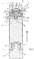
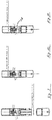
- a tool slide 1 according to the invention has a slide bed 2, a slide body 3 and a driver 4.
- the slide part 3 is arranged hanging on the slide bed 2 in the case shown, wherein the slide part 3 can be lifted off by the driver 4.
- the driver 4 is usually arranged in a first (in the case shown, the lower) half of the tool, while the slide part 3 is arranged over the slide bed 2 on a corresponding second (upper) tool half (not shown).
- the slide bed 2 is approximately box-shaped and has an elongated rectangular groove 5, 5 screw holes 6 being provided for receiving corresponding screws (not shown) in addition to the elongated rectangular groove.
- the groove and the adjacent surfaces 7 delimiting the groove form a bearing surface for L-shaped slide strips 8, which rest on the surfaces 7 and extend into the groove with an L-leg 9.
- the L-shaped slide strips 8 have mounting holes 10 for screwing in mounting screws for arrangement in the screw holes 6.
- the L-shaped slide strips 8 have inclined surfaces 11 pointing towards the center of the groove, with which they delimit a prismatic space between them.
- the L-shaped slide strips Towards the slide body 3, the L-shaped slide strips have slide surfaces 12 which are flat and perpendicular to an X-axis 13 shown.
- the slide body 3 has sliding surfaces or sliding strips 14 corresponding to the surfaces 12, which act as sliding partners the L-shaped slide strips 8 are formed.
- a guide body 15 extends upwards into the groove 5 symmetrically to the vertical axis between the slide strips 14.
- the guide body 15 has, for example, a guide prism 15 which has elongated prismatic surfaces 16 with which it bears on the surfaces 11 of the L-shaped slide strips.
- the guide body 15 is in this case designed as an elongated, rail-like or web-like component which extends prismatically into the area projecting into the groove 5 and is mounted in the slide body 3 with a T-shaped area 30.
- the slide body 3 has a T-shaped groove 31 which, adjacent to the sliding surfaces 14, has a narrower area 32 which opens out at the surface and widens away from the surface to form a T-shaped area 34.
- the guide body 15 has a narrower web-like area 35, which widens correspondingly in a T-shape to a crossbar-like area in the wider area of the groove.
- any other shape which widens from a narrower area to a further area can be used instead of an approximately T-shaped configuration for the safe guidance and holding of the guide body 15 in the slide body 3 the longitudinal extension of the guide body in cross section roundish rod-shaped widening, a triangular or prismatic widening and the like.
- the guide prism 15a which is arranged in the groove 5 can also have shapes other than a prismatic shape, as long as it is ensured by widening is that a hanging arrangement of the slide body in the slide bed is guaranteed.
- the slide body has further slide strips 17 which are arranged obliquely with respect to the X-axis 13 and correspond to prismatic guide surfaces 18 of the driver 4.
- the slanted corresponding sliding elements 17, 18 between the slide body and driver form a so-called prismatic guide.
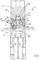
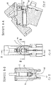
- the tool slide 1 also consists of a slide bed 2 and a slide body 3 (the driver 4 is not shown).
- the slide part 3 is arranged hanging on the slide bed 2 in the case shown, wherein the slide part 3 can be lifted off by the driver 4.
- the slide bed 2 is approximately box-shaped and has an elongated groove 5, the groove 5 having groove side walls 19 which run convergingly and thus form a dovetail groove section.
- the groove 5 bounding surfaces 7 converge with one another and run approximately perpendicular to the groove side walls 19 or parallel to the respective surfaces of the groove bottom 5a.
- L-shaped slide strips 8 lie on the surfaces 7 and extend into the groove with a narrow, short L-leg 9.
- the L-shaped sliding strips have contact surfaces 11 towards the surfaces 7 and sliding surfaces 12 towards the slide body 3, which are flat and diverging with respect to a vertical axis. These surfaces 12 slide on corresponding sliding surfaces 14 of the slide body 3.
- the sliding surfaces 14 of the slide body 3 are accordingly inclined roof-shaped, with the guide prism 15 of the slide body being arranged symmetrically in the center in relation to the vertical axis, the prismatic surfaces 16 being formed adjacent to the short L-shaped legs 9 of the slide strips 8.
- the surfaces 16 and 14 enclose the same angle as the surfaces 9, 12 and are approximately perpendicular to one another in the example shown.
- FIG. 2 Partial sectional view shown shows that the guide body 15 is secured in the groove 31 by axially pulling it out by means of a cover plate 36 with screw 37, the screw 37 being screwed into the slide body and the disk 36 parts of the groove 31 and the guide body 15 stored therein covered.
- This fuse is also in one embodiment Fig. 1 intended.
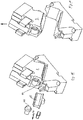
- a positive locking piece 40 is present in a further advantageous embodiment.
- the closure piece 40 is flattened cylindrical and has a bayonet-like closure with two opposite bayonet springs 41 and a projecting flange 42 on a second level.
- the bayonet springs 41 are in particular arranged on curved jacket walls 44 of the closure piece 40, while the projecting flange 42 is formed at a free end and projects beyond a flattened wall 45 of the closure piece 40.
- the bayonet-like lock with the springs 41 engages in a groove 46 and thus secures components arranged behind it (e.g. spring, guide piece) on different contact surfaces.
- the spring can be secured once in the center of the closure piece and on the projecting flange.
- the bayonet lock is designed in such a way that the bayonet-like geometry on the first level is released by rotating the lock piece 40 at a certain angle (e.g. 90 °), i.e. the springs 41 get out of the groove 46, and the closure piece can then be removed in the direction of arrow 43 from the assembly position.
- a certain angle e.g. 90 °
- the closure piece 40 is designed to be self-locking in the mounting position by means of a resilient pressure piece 47, which is arranged in particular in a bore 48 in a radial peripheral wall 49 of the projecting flange 42. In the assembly position, the resilient pressure piece 47 engages in a notch or bore 50 arranged opposite one another, so that a rotation of the closure piece 40 is only possible through an increased effort.
- the guide body 15 can be formed from a material which is made of the usual cast material of the slide body 3 deviates. Depending on the expected forces, z. B. Forged steels are used.
- the guide body hardened, to coat the guide body with hard material layers (for example in the PVD process) in order to achieve particularly high wear resistance.
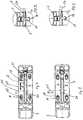
- the guide of the slide body in the slide bed must be adjustable or the slide strips 8 and the prism 15 must be adjusted to one another.
- the mounting holes 10 in the slide strips 8 are designed as elongated holes, so that they can be moved along the mounting screws 20 and thus along an adjustment direction 21.
- Moving the slide strips 8 along the direction 21 does not change any gaps or spacings that may be present between the surfaces of the slide strips 8 or the L-legs 9 and the guide prism 15.
- the contact surfaces 11 therefore run in relation to the longitudinal extent or the directions 21 the L-leg 9 of the L-shaped slide strips 8 obliquely. This means that they change their thickness in relation to the longitudinal extent.
- the slope has an incline of 1-5 degrees.
- the oblique contact surfaces 22 on the L-legs 9 of the L-shaped slide strips 8 are directed to corresponding corresponding surfaces 16 of the guide prism 15.
- Moving in the direction 21 thus has the effect that, due to the inclined surface 11, the distance between the L-legs 9 and the surfaces 16 is reduced or eliminated. Both slide rails 8 and only one slide rail 8 can be moved here.
- the groove side walls 19 - at least in the area where the surfaces 22 abut - can be designed with corresponding wedge-like or wedge-shaped bevels.
- a displacement along the direction 21 has the effect that the slide strips 8 are moved towards the guide prism 15 or are moved away therefrom. Since this is at the same time an approximation of the slide bars or removal of the slide bars in the transverse direction, d. H. in the direction 23, the elongated holes 10 are designed such that a floating mounting around the screws 20 is also possible in the direction 23.
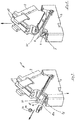
- a tool slide with a flat guide ( Fig. 1 ) can also be used to set a production-related offset between the slide bed with slide part in the slide upper part and the driver in the lower part ( 9 to 11 ).
- the slide bed with slide part is mounted on the tool with play between the slide strips 8 and the guide prism 15.
- the gap dimensions between the corresponding surfaces of the L-legs 9 and the guide prism 15 each have a first gap dimension.
- the invention relates to a tool slide, comprising at least one slide bed 2 and a slide body 3, wherein the slide part 3 on the slide bed 2 is axially movable to a limited extent and wherein a groove 5 is formed on the slide part 3 or on the slide bed 2 and a guide body 15 of the corresponding means Slider part 3 or the slider bed 2 is axially displaceably slidably mounted in the groove, the guide body 15 being rail-like or slat-like and with a partial width in the slider body 3 or in the slide bed 2 is arranged in a groove 31 inserted.
- the invention further relates to a tool slide, the guide body 15 having a thickening or widening 34 along a longitudinal edge mounted in the slide body.
- the invention relates to a tool slide, the guide body 15 widening from a narrower web-like area 35 to the longitudinal edge 26 in a T-shape to a cross-bar-like area 36.
- the invention also relates to a tool slide, the guide body 15 being fixed in the region of an axial mouth of the groove 31 in which it is fixed by a locking means 36, 37 against axial displacement.
- the invention further relates to a tool slide, the guide body 15 being designed as an elongated rail-like or web-like component, the guide body 15 being designed to expand prismatically into the area projecting into the groove 5, a guide prism 15a being formed in the groove 5 is supported, the guide body 15 having prismatic surfaces 16 being mounted on corresponding surfaces 11 of slide strips 8 in the groove 5.
Claims (9)
- Coulisseau porte-outil comprenant au moins une glissière coulissante (2) et un organe coulissant (3), l'élément coulissant (3) étant mobile coulissant sur la glissière coulissante (2) dans le sens axial de manière limitée et une rainure (5) étant formée sur l'élément coulissant (3) et la glissière coulissante (2) et un corps de guidage (15) étant logé coulissant dans le sens axial comme moyen correspondant dans les rainures de l'élément coulissant (3) et de la glissière coulissante (2), le corps de guidage (15) étant formé comme un rail ou une plaque et disposé inséré fixement dans une rainure (31) avec une largeur partielle dans l'organe coulissant (3) ou la glissière coulissante (2), le corps de guidage (15) étant fixé contre un déplacement axial avec un moyen de blocage (36, 37) dans la zone d'un trou axial de la rainure (31) dans lequel il est maintenu.
- Coulisseau porte-outil selon la revendication 1, caractérisé en ce que le corps de guidage (15) dispose d'un renflement ou d'un élargissement (34) le long d'un bord longitudinal logé dans l'organe coulissant.
- Coulisseau porte-outil selon la revendication 1 ou 2, caractérisé en ce que le corps de guidage (15) s'élargit d'une zone étroite en forme d'entretoise (35) par rapport au bord longitudinal (26) en forme de T par rapport à une zone en forme de traverse (36).
- Coulisseau porte-outil selon l'une des revendications précédentes, caractérisé en ce que le corps de guidage (15) est formé comme un composant en forme de rail ou de traverse allongée, le corps de guidage (15) se formant en s'élargissant en forme de prisme dans la zone pénétrant dans la rainure (5), un prisme de guidage (15a) étant formé logé dans la rainure (5), le corps de guidage (15) étant logé dans la rainure (5) avec des surfaces prismatiques (16) sur des surfaces correspondantes (11) de glissières (8).
- Coulisseau porte-outil selon l'une des revendications précédentes, caractérisé en ce qu'une pièce de sécurité (40) enveloppante est présente pour la sécurité du corps de guidage, l'obturateur (40) disposant d'une fermeture à baïonnette et coopérant avec des moyens de fermeture à baïonnette correspondants sur l'élément coulissant (3).
- Coulisseau porte-outil selon la revendication 6, caractérisé en ce que l'obturateur (40) dispose de deux baïonnettes à ressorts (41) opposées qui sont formées coopérantes avec respectivement une rainure (46) dans l'organe coulissant (3).
- Coulisseau porte-outil selon l'une des revendications précédentes, caractérisé en ce que l'obturateur (40) est de forme cylindrique aplatie et les baïonnettes à ressorts sont disposées sur des parois enveloppantes incurvées (44) de l'obturateur (40) tandis qu'une bride en saillie (42) est formée à une extrémité libre de l'obturateur (40) et ressort par une paroi aplatie (45) de l'obturateur (40), l'obturateur (40) sécurisant de manière adjacente des composants disposés derrière (par ex. ressort, pièce de guidage) sur différentes surfaces de contact.
- Coulisseau porte-outil selon l'une des revendications précédentes, caractérisé en ce que la fermeture à baïonnette est conçue de telle sorte que la géométrie en forme de baïonnette sur le premier niveau est libérée par une rotation de l'obturateur (40) dans un certain angle, c.-à-d. que les ressorts (41) dépassent de la rainure (46) de façon à pouvoir retirer l'obturateur (40) disposé dans une position de montage.
- Coulisseau porte-outil selon l'une des revendications précédentes, caractérisé en ce que l'obturateur (40) est disposé autobloquant dans la position de montage grâce à un élément de pression élastique (47) qui est disposé dans un trou d'une paroi circonférentielle radiale (49) de la bride (42), l'élément de pression élastique (47) en position de montage dans une encoche ou un trou (50) opposé de telle sorte qu'une rotation de l'obturateur (40) est possible par un effort accru uniquement.
Applications Claiming Priority (2)
| Application Number | Priority Date | Filing Date | Title |
|---|---|---|---|
| DE102014102993.3A DE102014102993B4 (de) | 2014-03-06 | 2014-03-06 | Werkzeugschieber |
| PCT/EP2015/054662 WO2015132355A1 (fr) | 2014-03-06 | 2015-03-05 | Coulisseau porte-outil |
Publications (2)
| Publication Number | Publication Date |
|---|---|
| EP3113892A1 EP3113892A1 (fr) | 2017-01-11 |
| EP3113892B1 true EP3113892B1 (fr) | 2020-05-06 |
Family
ID=52672249
Family Applications (1)
| Application Number | Title | Priority Date | Filing Date |
|---|---|---|---|
| EP15709660.3A Active EP3113892B1 (fr) | 2014-03-06 | 2015-03-05 | Coulisseau porte-outil |
Country Status (7)
| Country | Link |
|---|---|
| US (1) | US20170014889A1 (fr) |
| EP (1) | EP3113892B1 (fr) |
| JP (1) | JP2017508626A (fr) |
| KR (1) | KR20160129900A (fr) |
| CN (1) | CN106457351A (fr) |
| DE (1) | DE102014102993B4 (fr) |
| WO (1) | WO2015132355A1 (fr) |
Cited By (1)
| Publication number | Priority date | Publication date | Assignee | Title |
|---|---|---|---|---|
| DE102022108067B3 (de) | 2022-04-05 | 2023-04-27 | Dr. Ing. H.C. F. Porsche Aktiengesellschaft | Werkzeugschieber und Verfahren zum Montieren und/oder Demontieren |
Families Citing this family (3)
| Publication number | Priority date | Publication date | Assignee | Title |
|---|---|---|---|---|
| DE202015106966U1 (de) | 2015-12-21 | 2016-01-28 | Harald Weigelt | Keiltrieb |
| DE202017100989U1 (de) | 2017-02-22 | 2017-04-21 | Fibro Gmbh | Keiltrieb mit optimierter Führung |
| DE102018111366B4 (de) * | 2018-05-14 | 2024-03-07 | F I B R O Gmbh | Keiltrieb mit justierbarer Führungsvorrichtung |
Family Cites Families (19)
| Publication number | Priority date | Publication date | Assignee | Title |
|---|---|---|---|---|
| DE2329324B2 (de) * | 1973-06-08 | 1975-11-27 | Langenstein & Schemann Ag, 8630 Coburg | Keilpresse mit einer Einrichtung zur Verhinderung unerwünschter Bewegungen des Keiles |
| US3992920A (en) * | 1973-06-08 | 1976-11-23 | Langenstein & Schemann Aktiengesellschaft | Wedge press |
| DE2439217A1 (de) * | 1974-08-16 | 1976-03-04 | Langenstein & Schemann Ag | Keipresse mit einer keilfuehrung |
| DE2640318A1 (de) * | 1976-08-09 | 1978-03-16 | Weingarten Ag Maschf | Keiltrieb zur umleitung einer vertikalen presskraft in eine fuer den umformvorgang hierzu winklig wirkende kraft |
| ES2069654T3 (es) * | 1990-11-09 | 1995-05-16 | Umix Co Ltd | Matriz con leva deslizante. |
| DE19753549C2 (de) * | 1997-12-03 | 2000-02-17 | Harald Weigelt | Keiltrieb |
| JP3757635B2 (ja) * | 1998-08-26 | 2006-03-22 | オイレス工業株式会社 | カム装置 |
| ES2265853T5 (es) * | 2000-10-13 | 2013-06-04 | Voestalpine Giesserei Linz Gmbh | Accionamiento de cuña |
| DE10340509A1 (de) * | 2003-09-03 | 2005-03-31 | Bayerische Motoren Werke Ag | Keiltriebwerkzeug mit zueinander verstellbaren Elementen zum schneidlosen Formen eines Blechwerkstückes in einer Presse |
| US6990844B1 (en) * | 2004-07-27 | 2006-01-31 | Anchor Lamina America, Inc. | Narrow aerial and die-mount cams |
| US7191635B2 (en) * | 2004-11-18 | 2007-03-20 | Danly Iem, Llc | Press mounted cam |
| DE102005029140B4 (de) * | 2005-06-23 | 2008-04-03 | Elke Weigelt | Werkzeugbefestigungseinrichtung für einen Keiltrieb |
| DE102007045703A1 (de) * | 2007-09-24 | 2009-04-09 | Harald Weigelt | Keiltrieb mit Schieberaufnahme |
| US8430385B2 (en) * | 2007-09-24 | 2013-04-30 | Harald Weigelt | Wedge drive with slider receiving means |
| DE102008061420B9 (de) * | 2008-12-10 | 2011-02-10 | voestalpine Gießerei Linz GmbH | Keiltrieb |
| JP2011140048A (ja) * | 2010-01-08 | 2011-07-21 | Sankyo Oilless Industry Inc | カム装置 |
| JP5210365B2 (ja) * | 2010-09-17 | 2013-06-12 | 株式会社ユアビジネス | プレス成形用金型 |
| KR101139272B1 (ko) * | 2011-02-16 | 2012-04-26 | 주식회사 루보 | 캠슬라이드의 편심구동방지수단이 구비된 에어리얼 캠 유니트 |
| DE102012014546A1 (de) * | 2012-07-21 | 2014-01-23 | Strack Norma Gmbh & Co. Kg | Keiltrieb |
-
2014
- 2014-03-06 DE DE102014102993.3A patent/DE102014102993B4/de not_active Expired - Fee Related
-
2015
- 2015-03-05 EP EP15709660.3A patent/EP3113892B1/fr active Active
- 2015-03-05 JP JP2016572907A patent/JP2017508626A/ja not_active Withdrawn
- 2015-03-05 KR KR1020167027679A patent/KR20160129900A/ko unknown
- 2015-03-05 CN CN201580012371.4A patent/CN106457351A/zh active Pending
- 2015-03-05 US US15/123,790 patent/US20170014889A1/en not_active Abandoned
- 2015-03-05 WO PCT/EP2015/054662 patent/WO2015132355A1/fr active Application Filing
Non-Patent Citations (1)
| Title |
|---|
| None * |
Cited By (1)
| Publication number | Priority date | Publication date | Assignee | Title |
|---|---|---|---|---|
| DE102022108067B3 (de) | 2022-04-05 | 2023-04-27 | Dr. Ing. H.C. F. Porsche Aktiengesellschaft | Werkzeugschieber und Verfahren zum Montieren und/oder Demontieren |
Also Published As
| Publication number | Publication date |
|---|---|
| CN106457351A (zh) | 2017-02-22 |
| EP3113892A1 (fr) | 2017-01-11 |
| DE102014102993A1 (de) | 2015-10-22 |
| DE102014102993B4 (de) | 2016-05-12 |
| JP2017508626A (ja) | 2017-03-30 |
| US20170014889A1 (en) | 2017-01-19 |
| KR20160129900A (ko) | 2016-11-09 |
| WO2015132355A1 (fr) | 2015-09-11 |
Similar Documents
| Publication | Publication Date | Title |
|---|---|---|
| EP2197660B1 (fr) | élément de translation mobile et transmission par clavette avec un tel élément de translation mobile | |
| EP1197319B2 (fr) | Entraînement par coin | |
| EP1893365B1 (fr) | Dispositif de fixation d'outil pour dispositif d'entraînement par came | |
| EP2874804B1 (fr) | Mécanisme à came | |
| EP2355943B1 (fr) | Mécanisme à clavette | |
| EP3393693B1 (fr) | Mécanisme à clavette | |
| EP3113892B1 (fr) | Coulisseau porte-outil | |
| EP3113891B1 (fr) | Coulisseau porte-outil | |
| DE102015103112B4 (de) | Werkzeugschieber | |
| DE112015000008B4 (de) | Werkzeugschieber | |
| DE3436075C1 (de) | Vorrichtung zur Ioesbaren Verbindung von Greiferschienenteilen der Greiferschienen in einer Transfer-Presse | |
| DE102009040840A1 (de) | Rohrbearbeitungsvorrichtung mit einer Schneideinrichtung | |
| EP1868759A1 (fr) | Dispositif pour former des parties saillantes, des dents, des copeaux, des retraits ou similaire dans une plaque support de garniture de frein | |
| DE102011115326B4 (de) | Positioniereinrichtung für eine Presseinrichtung und Presseinrichtung | |
| DE2538605A1 (de) | Stanzvorrichtung | |
| EP2885108B1 (fr) | Dispositif de levage avec mécanisme à genouillère | |
| EP1622731B1 (fr) | Dispositif porte-outil | |
| DE3151275A1 (de) | Befestigungsvorrichtung fuer werkzeuge | |
| EP0362753A1 (fr) | Dispositif de fixation | |
| EP3052265B1 (fr) | Installation d'ébavurage thermique comprenant un ensemble porteur mobile | |
| EP3095552B1 (fr) | Outil d'étalonnage | |
| DE102019218301A1 (de) | Verbindungssystem | |
| EP1338757A2 (fr) | Support interchangeable pour outils |
Legal Events
| Date | Code | Title | Description |
|---|---|---|---|
| STAA | Information on the status of an ep patent application or granted ep patent |
Free format text: STATUS: THE INTERNATIONAL PUBLICATION HAS BEEN MADE |
|
| PUAI | Public reference made under article 153(3) epc to a published international application that has entered the european phase |
Free format text: ORIGINAL CODE: 0009012 |
|
| STAA | Information on the status of an ep patent application or granted ep patent |
Free format text: STATUS: REQUEST FOR EXAMINATION WAS MADE |
|
| 17P | Request for examination filed |
Effective date: 20160902 |
|
| AK | Designated contracting states |
Kind code of ref document: A1 Designated state(s): AL AT BE BG CH CY CZ DE DK EE ES FI FR GB GR HR HU IE IS IT LI LT LU LV MC MK MT NL NO PL PT RO RS SE SI SK SM TR |
|
| AX | Request for extension of the european patent |
Extension state: BA ME |
|
| DAV | Request for validation of the european patent (deleted) | ||
| DAX | Request for extension of the european patent (deleted) | ||
| RAP1 | Party data changed (applicant data changed or rights of an application transferred) |
Owner name: VOESTALPINE CAMTEC GMBH |
|
| STAA | Information on the status of an ep patent application or granted ep patent |
Free format text: STATUS: EXAMINATION IS IN PROGRESS |
|
| 17Q | First examination report despatched |
Effective date: 20190704 |
|
| GRAP | Despatch of communication of intention to grant a patent |
Free format text: ORIGINAL CODE: EPIDOSNIGR1 |
|
| STAA | Information on the status of an ep patent application or granted ep patent |
Free format text: STATUS: GRANT OF PATENT IS INTENDED |
|
| GRAS | Grant fee paid |
Free format text: ORIGINAL CODE: EPIDOSNIGR3 |
|
| INTG | Intention to grant announced |
Effective date: 20200303 |
|
| GRAA | (expected) grant |
Free format text: ORIGINAL CODE: 0009210 |
|
| STAA | Information on the status of an ep patent application or granted ep patent |
Free format text: STATUS: THE PATENT HAS BEEN GRANTED |
|
| AK | Designated contracting states |
Kind code of ref document: B1 Designated state(s): AL AT BE BG CH CY CZ DE DK EE ES FI FR GB GR HR HU IE IS IT LI LT LU LV MC MK MT NL NO PL PT RO RS SE SI SK SM TR |
|
| REG | Reference to a national code |
Ref country code: GB Ref legal event code: FG4D Free format text: NOT ENGLISH |
|
| REG | Reference to a national code |
Ref country code: CH Ref legal event code: EP Ref country code: AT Ref legal event code: REF Ref document number: 1265969 Country of ref document: AT Kind code of ref document: T Effective date: 20200515 |
|
| REG | Reference to a national code |
Ref country code: DE Ref legal event code: R096 Ref document number: 502015012510 Country of ref document: DE |
|
| REG | Reference to a national code |
Ref country code: IE Ref legal event code: FG4D Free format text: LANGUAGE OF EP DOCUMENT: GERMAN |
|
| REG | Reference to a national code |
Ref country code: LT Ref legal event code: MG4D |
|
| REG | Reference to a national code |
Ref country code: NL Ref legal event code: MP Effective date: 20200506 |
|
| PG25 | Lapsed in a contracting state [announced via postgrant information from national office to epo] |
Ref country code: SE Free format text: LAPSE BECAUSE OF FAILURE TO SUBMIT A TRANSLATION OF THE DESCRIPTION OR TO PAY THE FEE WITHIN THE PRESCRIBED TIME-LIMIT Effective date: 20200506 Ref country code: LT Free format text: LAPSE BECAUSE OF FAILURE TO SUBMIT A TRANSLATION OF THE DESCRIPTION OR TO PAY THE FEE WITHIN THE PRESCRIBED TIME-LIMIT Effective date: 20200506 Ref country code: FI Free format text: LAPSE BECAUSE OF FAILURE TO SUBMIT A TRANSLATION OF THE DESCRIPTION OR TO PAY THE FEE WITHIN THE PRESCRIBED TIME-LIMIT Effective date: 20200506 Ref country code: NO Free format text: LAPSE BECAUSE OF FAILURE TO SUBMIT A TRANSLATION OF THE DESCRIPTION OR TO PAY THE FEE WITHIN THE PRESCRIBED TIME-LIMIT Effective date: 20200806 Ref country code: GR Free format text: LAPSE BECAUSE OF FAILURE TO SUBMIT A TRANSLATION OF THE DESCRIPTION OR TO PAY THE FEE WITHIN THE PRESCRIBED TIME-LIMIT Effective date: 20200807 Ref country code: PT Free format text: LAPSE BECAUSE OF FAILURE TO SUBMIT A TRANSLATION OF THE DESCRIPTION OR TO PAY THE FEE WITHIN THE PRESCRIBED TIME-LIMIT Effective date: 20200907 Ref country code: IS Free format text: LAPSE BECAUSE OF FAILURE TO SUBMIT A TRANSLATION OF THE DESCRIPTION OR TO PAY THE FEE WITHIN THE PRESCRIBED TIME-LIMIT Effective date: 20200906 |
|
| PG25 | Lapsed in a contracting state [announced via postgrant information from national office to epo] |
Ref country code: HR Free format text: LAPSE BECAUSE OF FAILURE TO SUBMIT A TRANSLATION OF THE DESCRIPTION OR TO PAY THE FEE WITHIN THE PRESCRIBED TIME-LIMIT Effective date: 20200506 Ref country code: LV Free format text: LAPSE BECAUSE OF FAILURE TO SUBMIT A TRANSLATION OF THE DESCRIPTION OR TO PAY THE FEE WITHIN THE PRESCRIBED TIME-LIMIT Effective date: 20200506 Ref country code: BG Free format text: LAPSE BECAUSE OF FAILURE TO SUBMIT A TRANSLATION OF THE DESCRIPTION OR TO PAY THE FEE WITHIN THE PRESCRIBED TIME-LIMIT Effective date: 20200806 Ref country code: RS Free format text: LAPSE BECAUSE OF FAILURE TO SUBMIT A TRANSLATION OF THE DESCRIPTION OR TO PAY THE FEE WITHIN THE PRESCRIBED TIME-LIMIT Effective date: 20200506 |
|
| PG25 | Lapsed in a contracting state [announced via postgrant information from national office to epo] |
Ref country code: NL Free format text: LAPSE BECAUSE OF FAILURE TO SUBMIT A TRANSLATION OF THE DESCRIPTION OR TO PAY THE FEE WITHIN THE PRESCRIBED TIME-LIMIT Effective date: 20200506 Ref country code: AL Free format text: LAPSE BECAUSE OF FAILURE TO SUBMIT A TRANSLATION OF THE DESCRIPTION OR TO PAY THE FEE WITHIN THE PRESCRIBED TIME-LIMIT Effective date: 20200506 |
|
| PG25 | Lapsed in a contracting state [announced via postgrant information from national office to epo] |
Ref country code: RO Free format text: LAPSE BECAUSE OF FAILURE TO SUBMIT A TRANSLATION OF THE DESCRIPTION OR TO PAY THE FEE WITHIN THE PRESCRIBED TIME-LIMIT Effective date: 20200506 Ref country code: CZ Free format text: LAPSE BECAUSE OF FAILURE TO SUBMIT A TRANSLATION OF THE DESCRIPTION OR TO PAY THE FEE WITHIN THE PRESCRIBED TIME-LIMIT Effective date: 20200506 Ref country code: ES Free format text: LAPSE BECAUSE OF FAILURE TO SUBMIT A TRANSLATION OF THE DESCRIPTION OR TO PAY THE FEE WITHIN THE PRESCRIBED TIME-LIMIT Effective date: 20200506 Ref country code: EE Free format text: LAPSE BECAUSE OF FAILURE TO SUBMIT A TRANSLATION OF THE DESCRIPTION OR TO PAY THE FEE WITHIN THE PRESCRIBED TIME-LIMIT Effective date: 20200506 Ref country code: IT Free format text: LAPSE BECAUSE OF FAILURE TO SUBMIT A TRANSLATION OF THE DESCRIPTION OR TO PAY THE FEE WITHIN THE PRESCRIBED TIME-LIMIT Effective date: 20200506 Ref country code: SM Free format text: LAPSE BECAUSE OF FAILURE TO SUBMIT A TRANSLATION OF THE DESCRIPTION OR TO PAY THE FEE WITHIN THE PRESCRIBED TIME-LIMIT Effective date: 20200506 Ref country code: DK Free format text: LAPSE BECAUSE OF FAILURE TO SUBMIT A TRANSLATION OF THE DESCRIPTION OR TO PAY THE FEE WITHIN THE PRESCRIBED TIME-LIMIT Effective date: 20200506 |
|
| REG | Reference to a national code |
Ref country code: DE Ref legal event code: R097 Ref document number: 502015012510 Country of ref document: DE |
|
| PG25 | Lapsed in a contracting state [announced via postgrant information from national office to epo] |
Ref country code: SK Free format text: LAPSE BECAUSE OF FAILURE TO SUBMIT A TRANSLATION OF THE DESCRIPTION OR TO PAY THE FEE WITHIN THE PRESCRIBED TIME-LIMIT Effective date: 20200506 Ref country code: PL Free format text: LAPSE BECAUSE OF FAILURE TO SUBMIT A TRANSLATION OF THE DESCRIPTION OR TO PAY THE FEE WITHIN THE PRESCRIBED TIME-LIMIT Effective date: 20200506 |
|
| PLBE | No opposition filed within time limit |
Free format text: ORIGINAL CODE: 0009261 |
|
| STAA | Information on the status of an ep patent application or granted ep patent |
Free format text: STATUS: NO OPPOSITION FILED WITHIN TIME LIMIT |
|
| 26N | No opposition filed |
Effective date: 20210209 |
|
| PG25 | Lapsed in a contracting state [announced via postgrant information from national office to epo] |
Ref country code: SI Free format text: LAPSE BECAUSE OF FAILURE TO SUBMIT A TRANSLATION OF THE DESCRIPTION OR TO PAY THE FEE WITHIN THE PRESCRIBED TIME-LIMIT Effective date: 20200506 |
|
| PG25 | Lapsed in a contracting state [announced via postgrant information from national office to epo] |
Ref country code: MC Free format text: LAPSE BECAUSE OF FAILURE TO SUBMIT A TRANSLATION OF THE DESCRIPTION OR TO PAY THE FEE WITHIN THE PRESCRIBED TIME-LIMIT Effective date: 20200506 |
|
| REG | Reference to a national code |
Ref country code: CH Ref legal event code: PL |
|
| GBPC | Gb: european patent ceased through non-payment of renewal fee |
Effective date: 20210305 |
|
| REG | Reference to a national code |
Ref country code: BE Ref legal event code: MM Effective date: 20210331 |
|
| PG25 | Lapsed in a contracting state [announced via postgrant information from national office to epo] |
Ref country code: LU Free format text: LAPSE BECAUSE OF NON-PAYMENT OF DUE FEES Effective date: 20210305 Ref country code: LI Free format text: LAPSE BECAUSE OF NON-PAYMENT OF DUE FEES Effective date: 20210331 Ref country code: CH Free format text: LAPSE BECAUSE OF NON-PAYMENT OF DUE FEES Effective date: 20210331 Ref country code: FR Free format text: LAPSE BECAUSE OF NON-PAYMENT OF DUE FEES Effective date: 20210331 Ref country code: GB Free format text: LAPSE BECAUSE OF NON-PAYMENT OF DUE FEES Effective date: 20210305 Ref country code: IE Free format text: LAPSE BECAUSE OF NON-PAYMENT OF DUE FEES Effective date: 20210305 |
|
| REG | Reference to a national code |
Ref country code: AT Ref legal event code: MM01 Ref document number: 1265969 Country of ref document: AT Kind code of ref document: T Effective date: 20210305 |
|
| PG25 | Lapsed in a contracting state [announced via postgrant information from national office to epo] |
Ref country code: BE Free format text: LAPSE BECAUSE OF NON-PAYMENT OF DUE FEES Effective date: 20210331 |
|
| PG25 | Lapsed in a contracting state [announced via postgrant information from national office to epo] |
Ref country code: AT Free format text: LAPSE BECAUSE OF NON-PAYMENT OF DUE FEES Effective date: 20210305 |
|
| PG25 | Lapsed in a contracting state [announced via postgrant information from national office to epo] |
Ref country code: HU Free format text: LAPSE BECAUSE OF FAILURE TO SUBMIT A TRANSLATION OF THE DESCRIPTION OR TO PAY THE FEE WITHIN THE PRESCRIBED TIME-LIMIT; INVALID AB INITIO Effective date: 20150305 |
|
| PGFP | Annual fee paid to national office [announced via postgrant information from national office to epo] |
Ref country code: DE Payment date: 20230329 Year of fee payment: 9 |
|
| PG25 | Lapsed in a contracting state [announced via postgrant information from national office to epo] |
Ref country code: CY Free format text: LAPSE BECAUSE OF FAILURE TO SUBMIT A TRANSLATION OF THE DESCRIPTION OR TO PAY THE FEE WITHIN THE PRESCRIBED TIME-LIMIT Effective date: 20200506 |