EP1197319B2 - Entraînement par coin - Google Patents
Entraînement par coin Download PDFInfo
- Publication number
- EP1197319B2 EP1197319B2 EP00122406A EP00122406A EP1197319B2 EP 1197319 B2 EP1197319 B2 EP 1197319B2 EP 00122406 A EP00122406 A EP 00122406A EP 00122406 A EP00122406 A EP 00122406A EP 1197319 B2 EP1197319 B2 EP 1197319B2
- Authority
- EP
- European Patent Office
- Prior art keywords
- guiding
- guide
- cam
- cotter key
- slide
- Prior art date
- Legal status (The legal status is an assumption and is not a legal conclusion. Google has not performed a legal analysis and makes no representation as to the accuracy of the status listed.)
- Expired - Lifetime
Links
Images

Classifications
-
- B—PERFORMING OPERATIONS; TRANSPORTING
- B21—MECHANICAL METAL-WORKING WITHOUT ESSENTIALLY REMOVING MATERIAL; PUNCHING METAL
- B21D—WORKING OR PROCESSING OF SHEET METAL OR METAL TUBES, RODS OR PROFILES WITHOUT ESSENTIALLY REMOVING MATERIAL; PUNCHING METAL
- B21D28/00—Shaping by press-cutting; Perforating
- B21D28/24—Perforating, i.e. punching holes
- B21D28/32—Perforating, i.e. punching holes in other articles of special shape
Definitions
- the invention relates to a wedge drive with an upper guide part, comprising a slider element and a slider guide element, and a lower guide part, comprising a driver element.
- wedge drives are known. They are used in particular in tools in metalworking, for example in presses. Connected with the wedge drives are usually the punching or otherwise deforming enabling facilities.
- the wedge drives are moved by the slider guide element by a drive applying a generally vertical pressing force.
- the wedge drives are mounted in the tool or the press on a base plate on which the workpiece to be machined is placed directly or via a corresponding support device.
- goes from the DE-197 53 549 C2 such a wedge drive for deflecting a vertical pressing force having a driving element with a prismatic surface.
- the flanks of the prismatic surface are hereby sloping downwards.
- forced return brackets are disposed on two opposite sides in respective grooves of the slider element and the driver element. In this way, in the event of breakage of a spring member retrieving the slider element into its starting position, a return of the slider element is ensured in the event of a spring break, in order thereby to prevent tearing out of screwed-on punching elements.
- the slider element is attached to the slider guide member via angle brackets and retaining screws and can be moved along the angle strips with respect to the slider guide element.
- the JP 7-290168 discloses a wedge drive with an upper part, a holding device connected thereto, a slider connected thereto and a driver connected thereto.
- the slider and the driver are connected to each other via two brackets.
- the upper part is also connected to the driver via a clamp.
- the US 5,904,064 discloses a wedge drive with a holding device, comprising two guide springs, a slider and a driver, wherein slide and driver are connected to each other via two brackets.
- the present invention is therefore based on the object to remedy these disadvantages and to provide a wedge drive, whose service life is considerably higher than in the wedge drives of the prior art and in the possible no impairment of the running play can occur.
- a wedge drive according to the preamble of claim 1, characterized in that the upper guide part (10, 20) by at least one guide clip (30) is held together and / or held together, wherein the at least one guide bracket (30), the slide element (20 ) and the slide guide element (10) with each other, wherein the guide clip (30) positively engages in the slider guide element (10) and the slider element (20), wherein the wedge drive is formed so that the at least one guide bracket (30) holding projections (31) by means of which it engages in a part (11) of the slide guide element (10), wherein the holding projections have a chamfer (32) and the chamfer is a small chamfer and allow the guide brackets a linear adjustment of the guide clearance.
- a wedge drive is created in which, in particular, slide element and slide guide element are held together by means of at least one guide clip.
- the running clearance is not affected even when heating the wedge drive or the tool, since not only manufacturing tolerances, but also occurring expansions of the material can be absorbed by the connection via a guide bracket.
- the stability of the wedge drive is therefore no longer impaired or shortened.
- the cost of the wedge drive can be significantly reduced, since not only a lower material cost, but also less effort in the assembly of slide guide element, slide element and driver element is required.
- the guide bracket or the guide brackets are positively engaged in the slider guide element or engages / engage there form-fitting.
- the slider element thus depends on the guide brackets on the slider guide element via this positive engagement.
- advantageously considerably higher holding forces between the slide element and slide guide element can be achieved than is possible in the prior art.
- the service life of the wedge drive can be increased many times.
- the at least one guide clip has retaining projections, by means of which it engages in a part of the slider guide element, wherein the retaining projections have a chamfer.
- the retaining projections may for example be formed nose-shaped on a substantially flat body of the guide clip. In another preferred embodiment, they are formed as in the longitudinal direction of the guide bracket directed, projecting from the flat body of the clip wedges.
- the retaining projections have a slight chamfer, in particular a bevel of about 1 ° in the direction of the driver element. This chamfer is preferably provided only on one side of the retaining projections and makes it possible to move the at least one guide bracket in the stroke direction of the wedge drive linear and parallel.
- Each item produced on the tool generally has its own tolerance field, wherein the slider guide element in this area to achieve the required running accuracy may only have a sliding clearance of in particular 0.02 mm.
- the slider guide element in this area to achieve the required running accuracy may only have a sliding clearance of in particular 0.02 mm.
- a screwing of slide element and slide guide element is provided, as continuous rework, coupled with permanent installation and removal is required.
- a guide bracket can be advantageously changed by their mere parallel sliding the sliding clearance, whereby the individual previously required operations are unnecessary, namely the measurement and grinding of the individual elements of the wedge drive. Manufacturing tolerances can thus be compensated advantageous, resulting in significantly lower production costs of the items to be manufactured.
- slide element and slide guide element have essentially the same width.
- they preferably have substantially parallel surfaces on which the at least one guide clip can be fastened.
- This proves to be advantageous since a wedge drive not only in the region of its lower guide part with a constant sliding clearance of e.g. 0.02 mm should be performed, but also towards the sides, which proves to be very complicated with the wedge drives of the prior art.
- guide brackets in conjunction with slide element and slide guide element of substantially the same width can be omitted on the one hand a complex grinding of the adjacent or -liding surfaces.
- the lower and / or upper guide part has a prismatic part and / or at least one prismatic surface for guiding the slider element and / or for receiving lateral forces for generating a high running accuracy.
- the prismatic part and / or the prismatic surface can advantageously be provided in the lower guide part for driving and / or for guiding the upper guide part.
- the larger the prismatic part / the prismatic surface the easier and thus better the upper guide part can be driven and guided thereon or in particular the slider element on the driver element.
- the slider guide element and / or slide element can also have prismatic surfaces, in particular surfaces sliding on one another or surfaces which can be joined to one another.
- the prismatic part / the prismatic surface is dimensioned depending on the dimensions, in particular the width and the other design of the slide element.
- the wedge drive preferably has a uniform width over its entire width extension. It is thus possible to ideally dimension the prismatic part / prismatic surface with respect to the width of the slider element, which exerts a tremendous influence on the running and service life of the wedge drive.
- a driver element or slider guide element or slider element with a particularly large prismatic surface or a particularly large prismatic part is advantageously able to absorb larger compressive forces in the vertical direction, better intercept lateral shear forces on its V-shape and thus to increase the running accuracy. Increased running accuracy in conjunction with greater compressive forces is a goal of a wedge drive.
- the actual width of the wedge drive has an influence on the degree of stability of the driver element. It can be achieved by the use of the prismatic part / the prismatic surface thus a further improvement of the running and service life of the wedge drive, in particular the achieved by the use of the guide clips compactness of slide guide element and slide element can be used even better for the effective processing of a workpiece ,
- a spring element in particular a gas spring, provided for retrieving the slider element, which is secured by means of a securing element, in particular a locking screw, in the slider element and disassembled above.
- a securing element in particular a locking screw
- the individual successive sliding elements of the wedge drive consist of a combination of materials bronze and hardened steel, in particular in combination with a lubricant, in particular a solid lubricant.
- the wear parts which are in any case more frequently to be changed, are preferably made of soft bronze, which wears faster than, for example, hardened steel.
- Forced return means for preventing the application of lateral moments to the wedge drive between the driver element and the slide element are preferably provided.
- the slider element is particularly preferably so connected to the driver element slidably connected or connected, that a lifting of the prismatic part / the prismatic surface of the driver element is made possible substantially only in the starting position.
- the forced return means may be formed like a clip and engage in a corresponding guide slot of the driver element, wherein it preferably engages in the slider element in a groove or a similar recess or recess.
- the wedge drive in the relevant area, in particular that of the slide element and driver element is preferably provided on both sides with forced return devices.
- a fixed surface for generating a reproducible starting position of the wedge drive between slide guide element and slide element is provided.
- the inclined fixed surface between the wedge drive and its receiving element can be selected as an adjustment, a spacer whose dimensions the desired Distance between a standing at a fixed angle to the inclined surface oblique surface of the wedge drive and the alignment surface correspond, placed on the adjustment surface be fixed in this position or the wedge drive in the tool to be fixed.
- a fixed surface may be an inner surface of the slide guide element, to which the spacer can be fitted and slide element can be moved counter with spring element.
- the adjustment surface initially serves as a reproducible fixed surface during initial assembly in the tool.
- the fixed surface proves to be particularly advantageous even when constantly checking and possibly changing the position of the wedge drive. This may be necessary in particular when the wedge drive is continuously moved back and forth during operation, in particular when the wedge drive moves a punch or a forming jaw, since the wedge drive is then always returned to a reproducible point or a reproducible surface and adjusted can be. As a result, therefore, a reproducible starting position is created.
- the required assembly times for adjusting and mounting the wedge drive can be shortened by using this method by about 80%, which also represents a significant amount of cost reduction.
- a further adjustment of the slide element and slide guide element with each other need not take place, since when using the guide brackets according to the invention, these two elements are already adjusted by the use of each other. It thus occurs here also no additional adjustment effort when using the guide brackets.
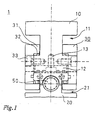
- FIG. 1 shows a plan view of a first embodiment of a wedge drive according to the invention 1.
- This comprises a slider guide element 10 and a slider element 20, which are interconnected by two guide brackets 30.
- a spring element 50 is also provided for displacing the slide element relative to the slide guide element.
- the spring element 50 is embedded in the slide element and in particular a gas pressure spring. This supports, as FIG. 2 and 3 can be better taken on the one hand on the slider guide element 10 and on the other side of the slider element 20 from.
- the guide brackets 30 each have retaining projections 31.
- the retaining projections 31 are provided with a respective bevel 32 which is directed towards the driver element, which is better FIG. 2 can be removed.
- the bevel is directed in particular at an angle of 1 ° to the driver element. This leads to a secure even with material expansion stop on slide guide element and slide element, a constant running play or sliding clearance and thus the possibility of a constant linear parallel displacement of the guide brackets on slider guide element and slider element to compensate for wear and other occurring tolerances.
- the holding projections 31 engage in corresponding grooves 11, 21 of slide guide element and slide element, whereby the guide clamps positively seated in at least the groove 11 of the slide guide element in the clamping direction.
- a sliding plate 12 is inserted between the two elements, which is fastened by means of screws 13 to the slide guide element.
- Slide guide element and slide element have in the region of the guide brackets 30 has a substantially equal width, whereby this can lie flat against the outer surfaces of slide guide element and slide element.
- Also in the area outside of the grooves 11, 21 have slider guide element, slide element and the outer surfaces of the guide brackets on a substantially equal width or form a substantially flat surface.
- FIG. 1 in this respect represents a plan view corresponding to the arrow X.
- the wedge drive shown in the working position.
- the slider element which has an inclined surface 23, along which it bears against the slide plate 12, which is also arranged obliquely in space, moved along the driver element 40 in the working position.
- a punching or deformation of a workpiece can be performed, for which purpose on the side 22 of the slider element 20, a corresponding additional device is attached.
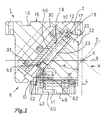
- the obliquely arranged spring element 50 is supported on a slide plate 12 substantially perpendicular to the inner surface 14 of the slide guide element 10 and is mounted on the opposite side via a bearing plate 51 and a bearing member 52 mounted thereon, which is screwed into the slide element in the slide member 20 ,
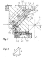
- the spring element serves to return the slider element to the starting position, which in FIG. 3 is shown withdraw.
- a return force can be, for example, 800 Newton, wherein the pressing force which is exerted on the slider guide element on the slider element, can be 3 tons.
- This pressing force is achieved by a corresponding drive device, which in FIG. 2 is not shown, introduced at the top 15 of the slide guide element.
- a recess 16 and two outer through holes 17 are provided there.
- the bearing plate 51 has to be loosened by loosening the screw 53 provided thereon and the spring element removed. This is preferably done from direction X, in FIG. 2 is indicated. In the same direction, a new spring element can be used and secured by the bearing plate with the screw 53 again in the slider element.
- the driver element 40 Lifting of the upper guide part, consisting of slide guide element and slide element of the lower guide part, the driver element 40 is therefore only in the starting position, namely the in FIG. 3 shown position of the slide element possible.
- the lower holding projection of the forced return device 60 has left the travel gate 41, which is why a lifting of the upper guide part of the lower guide member is made possible in this position.
- This advantageously prevents damage to a deforming or punching device mounted on the side 22 of the slide element which, in the working position, has been retracted into a workpiece for its processing and could be destroyed in this position while leaving the possibility of a direct decrease.
- the removal of the upper guide part is required, for example, in the event of a fault in order to be able to remedy this as quickly as possible.
- a fixed surface 2 is preferably defined in the tool, based on which an adjustment of the wedge drive in the initial assembly as well as later on and Removals can be done.
- this fixed surface 2 and other lines are indicated, which are arranged parallel to further slopes, horizontal and vertical surfaces of the upper and lower guide part of the wedge drive.
- the fixed surface 2 is preferably located on the stop surface of the spring element or the slide element. It can in principle also lie on the opposite side of the spring element in the slider guide element 10, but then serves the end of the spring element as ab todes part, not the slider element 20 itself.
- the base 42 of the driver element is not displaced during operation in height. How to compare the Figures 2 and 3 can be removed, however, the slider guide element is moved during operation with respect to its altitude relative to the horizontal line 3.
- the side 22 of the slider element only changes its distance from the vertical line 4 during operation.
- a line 5 parallel to the inclined surface 23 is formed. The distance of the surface 23 to the line 5 changes preferably not during operation. All lines 3, 4, 5 meet in a so-called tooling point 6, which is a standardization part.
- spacer used which has parallel walls whose spacing corresponds to the distance between an adjustment or fixed surface 2, and the outer surface 18 of the slider element 20 in the starting position.
- the spacer is applied to the inclined fixed surface 2 with respect to the outer surface 18 and makes it possible to adjust the wedge drive in this position, ie parallel to the fixed surface 2. Precisely because of the height of the forces to be deflected by the wedge drive, an accurate adjustment should take place here.
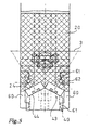
- the travels, which are covered during the deflection of the forces of the individual components of the wedge drive are in FIG. 4 shown.
- the length a is the travel path by which the slider guide element and slider element are displaced from each other
- the length b the travel by which the pressing force exerted on the slider guide member vertically displaces this in height
- the length c the travel to which the slider element is then moved along the driver element.
- the travel lengths a, b, c can be chosen arbitrarily, which in particular may result in a different aspect ratio with each other in comparison to the one shown.
- FIG. 5 shows a plan view of the slider element and a part of the driver element in the direction of arrow Y according to FIG. 2 .
- slide element and drive element are connected by the forced return devices 60.
- the slider element runs on a prismatic part 43 of the driver element.
- sliding plates 24 are fitted to produce better sliding properties, which are mounted on the underside of the slider element 20.
- the two sliding plates 24 are supported on the two flanks 44 of the prismatic part 43.
- the two flanks 44 are arranged at a relatively shallow angle to each other, so that there is a relatively large width of the tread. As a result, an accurate guidance of the slider element on the driver element can be achieved.
- the driver element in the illustrated case is narrower than the slide element, but this has substantially the same width as the slide guide element, and the slider element sits symmetrically on the driver element or its prismatic part, there are no shifts in the force ratio on the two flanks 44th on, so that also here a very good smooth running characteristic can be achieved. Lateral shear forces can also be very well absorbed and larger pressing forces are absorbed very well in the vertical direction. Due to the provision of the two guide brackets on both sides of the slider guide element and the slider element and the spring element centered in the body of the slide element introduced into the slide guide element pressing forces can be distributed evenly over the entire wedge drive, so that the running accuracy and smoothness when moving the slider element on the prismatic part of the driver element can be optimized.
- the fixed surface 2 and / or the opposite surface 19 are formed as a prism in another embodiment. Such a prism can absorb particularly well even higher forces.
- the other sliding surfaces, in particular sliding surface 18 and surface 23, may also have prismatic shape.
- the successive surfaces are preferably made of a combination of materials of a hard and a soft material, in particular a combination of soft bronze and hardened steel, preferably between both surfaces a lubricant, in particular a grease or solid lubricant is used, in particular oil and graphite.
- a lubricant in particular a grease or solid lubricant is used, in particular oil and graphite.
- the sliding plates 18, 24 are made of this material, whereas the driver element and slide element preferably made of hardened steel.
- the guide brackets 30 are made of bronze, in particular on the one hand to allow a good grip and on the other hand to provide a desired adjustability, if necessary to adjust the slide again accordingly.
- wedge drives in which in each case the upper guide part, in particular slider guide element and slide element, is held together by means of guide brackets.
- the arrangement and other physical training of the wedge drive can be chosen arbitrarily, as long as thereby the advantages that brings the connection of the elements of the upper guide member by guide brackets, not lost.
- the slider guide element can also be actuated by a horizontal pressing force, wherein the slider element is then moved vertically.
- the provision of the guide brackets proves to be advantageous.
- these may have a different orientation in space and a different shape, which is preferably adapted to the particular case.
- Guide brackets can thus be provided independently of the other configuration and Verfahrlage the wedge drive.
- wedge drives with guide brackets are inexpensive to produce, since in particular no reworking as in the prior art for adjustment purposes is required, which is regularly connected in the prior art with numerous outlets and internals of the wedge drive and its items, such as slide guide element and slide element.
Landscapes
- Mechanical Engineering (AREA)
- Engineering & Computer Science (AREA)
- Machine Tool Units (AREA)
- Mounting, Exchange, And Manufacturing Of Dies (AREA)
- Devices For Conveying Motion By Means Of Endless Flexible Members (AREA)
- Structure Of Belt Conveyors (AREA)
- Presses And Accessory Devices Thereof (AREA)
- Turning (AREA)
- Magnetic Heads (AREA)
- Push-Button Switches (AREA)
- Output Control And Ontrol Of Special Type Engine (AREA)
- General Details Of Gearings (AREA)
- Preparation Of Compounds By Using Micro-Organisms (AREA)
- Transition And Organic Metals Composition Catalysts For Addition Polymerization (AREA)
- Polysaccharides And Polysaccharide Derivatives (AREA)
- Slide Fasteners (AREA)
- Automotive Seat Belt Assembly (AREA)
Claims (11)
- Chasse-clavette avec un élément de guidage supérieur, contenant un élément curseur (20) et un élément de guidage du curseur (10) et avec un élément de guidage inférieur, contenant un élément chassoir (40), caractérisé en ce que l'élément de guidage supérieur (10, 20) peut être maintenu assemblé et/ou est maintenu assemblé par au moins un crampon de guidage (30) et que le au moins un crampon de guidage (30) relie entre eux l'élément curseur (20) et l'élément de guidage du curseur (10) et que le crampon de guidage (30) s'engage par complémentarité de forme dans l'élément de guidage du curseur (10) et dans l'élément curseur (20), le chasse-clavette étant formé de manière que le au moins un crampon de guidage (30) comporte des saillies de maintien (31) au moyen desquelles il s'engage dans une partie (11) de l'élément de guidage du curseur (10), les saillies de maintien comportant une inclinaison (32), qui est une faible inclinaison (32), les crampons de guidage permettant un ajustage linéaire du jeu de guidage.
- Chasse-clavette selon la revendication 1, caractérisé en ce que les saillies de maintien (31) comportent une faible inclinaison (32) de sensiblement 1° en direction de l'élément chassoir (40).
- Chasse-clavette selon la revendication 1 ou 2, caractérisé en ce que le crampon de guidage/les crampons de guidage (30) et l'élément de guidage supérieur (10, 20) peuvent s'engager l'un dans l'autre de façon telle, qu'un déplacement linéaire du crampon de guidage/des crampons de guidage dans le sens de levée du chasse-clavette (10) conduit à une modification du jeu de guidage à la transversale de la direction de circulation de l'élément chassoir (40) avec une linéarité sensiblement constante du jeu de guidage.
- Chasse-clavette selon l'une quelconque des revendications précédentes, caractérisé en ce que l'élément curseur (20) et l'élément de guidage du curseur (10) présentent sensiblement la même largeur et notamment sensiblement des surfaces parallèles, sur lesquelles on peut fixer le au moins un crampon de guidage (30).
- Chasse-clavette selon l'une quelconque des revendications précédentes, caractérisé en ce que l'élément de guidage inférieur et/ou supérieur (10, 20, 40) comporte un élément prismatique (43) et/ou au moins une surface prismatique pour le guidage de l'élément curseur (20) et/ou pour absorber des forces latérales pour générer une haute précision de fonctionnement.
- Chasse-clavette selon l'une quelconque des revendications précédentes, caractérisé en ce que le chasse-clavette (1) présente une largeur sensiblement constante sur l'ensemble de son extension en largeur.
- Chasse-clavette selon l'une quelconque des revendications précédentes, caractérisé en ce qu'on a prévu une ou plusieurs surfaces fixes (2) pour créer une position initiale reproductible du chasse-clavette entre l'élément de guidage du curseur et l'élément curseur.
- Chasse-clavette selon l'une quelconque des revendications précédentes, caractérisé en ce qu'on a prévu un élément à ressort (50), notamment un ressort à pression de gaz pour ramener l'élément curseur (20), qui est bloqué dans l'élément curseur au moyen d'un élément de blocage, notamment d'une vis de blocage (53) et qui est démontable par cet intermédiaire.
- Chasse-clavette selon l'une quelconque des revendications précédentes, caractérisé en ce que les éléments coulissant individuellement les uns sur les autres sont en un appariement de matières bronze et acier trempé, notamment en association avec un lubrifiant, notamment un lubrifiant solide.
- Chasse-clavette selon l'une quelconque des revendications précédentes, caractérisé en ce qu'on a prévu des dispositifs de rappel forcé (60), pour éviter l'action de moments latéraux sur le chasse-clavette, entre l'élément chassoir (40) et l'élément curseur (20).
- Chasse-clavette selon la revendication 10, caractérisé en ce que l'élément curseur (20) peut être relié ou est relié de façon déplaçable avec l'élément chassoir (40), de manière à ne permettre un soulèvement de l'élément prismatique (43) sensiblement que dans la position initiale.
Priority Applications (10)
| Application Number | Priority Date | Filing Date | Title |
|---|---|---|---|
| AT00122406T ATE337165T1 (de) | 2000-10-13 | 2000-10-13 | Keiltrieb |
| EP00122406A EP1197319B2 (fr) | 2000-10-13 | 2000-10-13 | Entraînement par coin |
| DE50013358T DE50013358D1 (de) | 2000-10-13 | 2000-10-13 | Keiltrieb |
| ES00122406T ES2265853T5 (es) | 2000-10-13 | 2000-10-13 | Accionamiento de cuña |
| AU2002215921A AU2002215921A1 (en) | 2000-10-13 | 2001-10-05 | V-belt drive |
| BRPI0114611-4A BR0114611B1 (pt) | 2000-10-13 | 2001-10-05 | correia trapezoidal, e, processo para o ajuste reproduzìvel da mesma. |
| PCT/EP2001/011478 WO2002030659A1 (fr) | 2000-10-13 | 2001-10-05 | Transmission par courroie trapezoidale |
| US10/399,198 US7114364B2 (en) | 2000-10-13 | 2001-10-05 | Cam slider |
| CA002425642A CA2425642C (fr) | 2000-10-13 | 2001-10-05 | Clavette et procede pour l'ajustement reproductible d'une clavette |
| MXPA03003056A MXPA03003056A (es) | 2000-10-13 | 2001-10-05 | Una llave de pasador. |
Applications Claiming Priority (1)
| Application Number | Priority Date | Filing Date | Title |
|---|---|---|---|
| EP00122406A EP1197319B2 (fr) | 2000-10-13 | 2000-10-13 | Entraînement par coin |
Publications (3)
| Publication Number | Publication Date |
|---|---|
| EP1197319A1 EP1197319A1 (fr) | 2002-04-17 |
| EP1197319B1 EP1197319B1 (fr) | 2006-08-23 |
| EP1197319B2 true EP1197319B2 (fr) | 2013-02-13 |
Family
ID=8170084
Family Applications (1)
| Application Number | Title | Priority Date | Filing Date |
|---|---|---|---|
| EP00122406A Expired - Lifetime EP1197319B2 (fr) | 2000-10-13 | 2000-10-13 | Entraînement par coin |
Country Status (10)
| Country | Link |
|---|---|
| US (1) | US7114364B2 (fr) |
| EP (1) | EP1197319B2 (fr) |
| AT (1) | ATE337165T1 (fr) |
| AU (1) | AU2002215921A1 (fr) |
| BR (1) | BR0114611B1 (fr) |
| CA (1) | CA2425642C (fr) |
| DE (1) | DE50013358D1 (fr) |
| ES (1) | ES2265853T5 (fr) |
| MX (1) | MXPA03003056A (fr) |
| WO (1) | WO2002030659A1 (fr) |
Cited By (1)
| Publication number | Priority date | Publication date | Assignee | Title |
|---|---|---|---|---|
| DE102022108067B3 (de) | 2022-04-05 | 2023-04-27 | Dr. Ing. H.C. F. Porsche Aktiengesellschaft | Werkzeugschieber und Verfahren zum Montieren und/oder Demontieren |
Families Citing this family (21)
| Publication number | Priority date | Publication date | Assignee | Title |
|---|---|---|---|---|
| DE102005029140B4 (de) | 2005-06-23 | 2008-04-03 | Elke Weigelt | Werkzeugbefestigungseinrichtung für einen Keiltrieb |
| DE102006036654B4 (de) * | 2006-08-03 | 2008-12-04 | Harald Weigelt | Keiltrieb mit Zwangsrückholeinrichtung |
| US8430385B2 (en) | 2007-09-24 | 2013-04-30 | Harald Weigelt | Wedge drive with slider receiving means |
| DE102007045703A1 (de) | 2007-09-24 | 2009-04-09 | Harald Weigelt | Keiltrieb mit Schieberaufnahme |
| DE102008061420B9 (de) * | 2008-12-10 | 2011-02-10 | voestalpine Gießerei Linz GmbH | Keiltrieb |
| IT1397576B1 (it) | 2009-04-14 | 2013-01-16 | Omcr S R L | Camma aerea per stampi |
| WO2011072024A2 (fr) * | 2009-12-08 | 2011-06-16 | Sankyo Oilless Industry (U.S.A. ) Corp. | Glissière de came et appareil de poinçon |
| JP2011140048A (ja) * | 2010-01-08 | 2011-07-21 | Sankyo Oilless Industry Inc | カム装置 |
| PL2552615T3 (pl) * | 2011-01-17 | 2018-01-31 | Gsb Oilles Imalat San Paz Tic Ltd Sti | Samosmarujący prowadnik płyty suwakowej |
| DE102015103114A1 (de) | 2014-03-06 | 2015-09-10 | Voestalpine Giesserei Linz Gmbh | Verbesserter Werkzeugschieber und Verfahren zu seiner Herstellung |
| DE102015103112B4 (de) | 2014-03-06 | 2019-10-10 | voestalpine Gießerei Linz GmbH | Werkzeugschieber |
| DE102014102993B4 (de) | 2014-03-06 | 2016-05-12 | Voestalpine Giesserei Linz Gmbh | Werkzeugschieber |
| EP3113891B1 (fr) | 2014-03-06 | 2018-05-16 | Voestalpine Giesserei Linz GmbH | Coulisseau porte-outil |
| KR20160129901A (ko) * | 2014-03-06 | 2016-11-09 | 푀스트알피네 기서라이 린쯔 게엠베하 | 공구 이송대 |
| JP1620160S (fr) * | 2018-03-30 | 2018-12-10 | ||
| DE102018111366B4 (de) * | 2018-05-14 | 2024-03-07 | F I B R O Gmbh | Keiltrieb mit justierbarer Führungsvorrichtung |
| JP1631354S (fr) * | 2018-10-16 | 2019-05-13 | ||
| JP7261984B2 (ja) * | 2019-09-18 | 2023-04-21 | パナソニックIpマネジメント株式会社 | 打ち抜き装置 |
| IT201900018953A1 (it) | 2019-10-16 | 2021-04-16 | O M C R S R L | Camma per stampi |
| CN111036818B (zh) * | 2019-12-18 | 2020-08-07 | 荣成华东锻压机床股份有限公司 | 一种锻造机械压力机刚度提升装置 |
| JP1707599S (ja) * | 2021-07-29 | 2022-02-16 | カムユニット |
Citations (8)
| Publication number | Priority date | Publication date | Assignee | Title |
|---|---|---|---|---|
| JPS6480115A (en) † | 1987-09-21 | 1989-03-27 | Nihon Dempa Kogyo Co | Piezoelectric vibrator |
| US5487296A (en) † | 1992-01-09 | 1996-01-30 | Connell Limited Partnership | Univers cam unit |
| US5884521A (en) † | 1998-07-10 | 1999-03-23 | Lamina, Inc. | High performance aerial and die mount cams |
| JPH11319992A (ja) † | 1998-05-15 | 1999-11-24 | Sankyo Oilless Kogyo Kk | カムユニット |
| JPH11319993A (ja) † | 1998-05-15 | 1999-11-24 | Sankyo Oilless Kogyo Kk | カムユニット |
| JP2000117328A (ja) † | 1998-10-15 | 2000-04-25 | Sankyo Oilless Kogyo Kk | カムスライダーとカムユニット |
| EP1136151A1 (fr) † | 2000-03-17 | 2001-09-26 | Sankyo Oilless Industry, Inc. | Coulisseau à auto-centrage |
| EP1136152A1 (fr) † | 2000-03-17 | 2001-09-26 | Sankyo Oilless Industry, Inc. | Coulisseau et ensemble de coulisseau |
Family Cites Families (9)
| Publication number | Priority date | Publication date | Assignee | Title |
|---|---|---|---|---|
| DE69018082T2 (de) * | 1990-11-09 | 1995-09-28 | Umix Co Ltd | Gesenk mit Führungsschlitten. |
| JP3387207B2 (ja) * | 1994-04-25 | 2003-03-17 | オイレス工業株式会社 | プレス用カム型 |
| JP3610606B2 (ja) * | 1994-12-27 | 2005-01-19 | オイレス工業株式会社 | プレス用カム型 |
| JPH10235437A (ja) * | 1997-02-25 | 1998-09-08 | Sankyo Oiruresu Kogyo Kk | プレス金型用のカムユニット |
| JP2880490B1 (ja) * | 1997-11-14 | 1999-04-12 | ユミックス株式会社 | プレス装置 |
| DE19753549C2 (de) * | 1997-12-03 | 2000-02-17 | Harald Weigelt | Keiltrieb |
| GB2342063A (en) * | 1998-09-30 | 2000-04-05 | Rover Group | A press tool and a wear block therefor |
| US6889535B1 (en) * | 1999-11-17 | 2005-05-10 | Hyfotec Sweden Ab | Tool assembly |
| JP2002316223A (ja) * | 2001-04-18 | 2002-10-29 | Umix Co Ltd | プレス装置 |
-
2000
- 2000-10-13 ES ES00122406T patent/ES2265853T5/es not_active Expired - Lifetime
- 2000-10-13 DE DE50013358T patent/DE50013358D1/de not_active Expired - Lifetime
- 2000-10-13 AT AT00122406T patent/ATE337165T1/de active
- 2000-10-13 EP EP00122406A patent/EP1197319B2/fr not_active Expired - Lifetime
-
2001
- 2001-10-05 WO PCT/EP2001/011478 patent/WO2002030659A1/fr active Application Filing
- 2001-10-05 US US10/399,198 patent/US7114364B2/en not_active Expired - Lifetime
- 2001-10-05 MX MXPA03003056A patent/MXPA03003056A/es active IP Right Grant
- 2001-10-05 CA CA002425642A patent/CA2425642C/fr not_active Expired - Lifetime
- 2001-10-05 AU AU2002215921A patent/AU2002215921A1/en not_active Abandoned
- 2001-10-05 BR BRPI0114611-4A patent/BR0114611B1/pt not_active IP Right Cessation
Patent Citations (8)
| Publication number | Priority date | Publication date | Assignee | Title |
|---|---|---|---|---|
| JPS6480115A (en) † | 1987-09-21 | 1989-03-27 | Nihon Dempa Kogyo Co | Piezoelectric vibrator |
| US5487296A (en) † | 1992-01-09 | 1996-01-30 | Connell Limited Partnership | Univers cam unit |
| JPH11319992A (ja) † | 1998-05-15 | 1999-11-24 | Sankyo Oilless Kogyo Kk | カムユニット |
| JPH11319993A (ja) † | 1998-05-15 | 1999-11-24 | Sankyo Oilless Kogyo Kk | カムユニット |
| US5884521A (en) † | 1998-07-10 | 1999-03-23 | Lamina, Inc. | High performance aerial and die mount cams |
| JP2000117328A (ja) † | 1998-10-15 | 2000-04-25 | Sankyo Oilless Kogyo Kk | カムスライダーとカムユニット |
| EP1136151A1 (fr) † | 2000-03-17 | 2001-09-26 | Sankyo Oilless Industry, Inc. | Coulisseau à auto-centrage |
| EP1136152A1 (fr) † | 2000-03-17 | 2001-09-26 | Sankyo Oilless Industry, Inc. | Coulisseau et ensemble de coulisseau |
Cited By (1)
| Publication number | Priority date | Publication date | Assignee | Title |
|---|---|---|---|---|
| DE102022108067B3 (de) | 2022-04-05 | 2023-04-27 | Dr. Ing. H.C. F. Porsche Aktiengesellschaft | Werkzeugschieber und Verfahren zum Montieren und/oder Demontieren |
Also Published As
| Publication number | Publication date |
|---|---|
| WO2002030659A1 (fr) | 2002-04-18 |
| MXPA03003056A (es) | 2004-12-06 |
| CA2425642C (fr) | 2008-02-12 |
| DE50013358D1 (de) | 2006-10-05 |
| ATE337165T1 (de) | 2006-09-15 |
| US7114364B2 (en) | 2006-10-03 |
| BR0114611B1 (pt) | 2010-10-19 |
| BR0114611A (pt) | 2003-12-23 |
| AU2002215921A1 (en) | 2002-04-22 |
| EP1197319B1 (fr) | 2006-08-23 |
| ES2265853T3 (es) | 2007-03-01 |
| US20040025561A1 (en) | 2004-02-12 |
| ES2265853T5 (es) | 2013-06-04 |
| CA2425642A1 (fr) | 2003-04-14 |
| EP1197319A1 (fr) | 2002-04-17 |
Similar Documents
| Publication | Publication Date | Title |
|---|---|---|
| EP1197319B2 (fr) | Entraînement par coin | |
| EP2197660B1 (fr) | élément de translation mobile et transmission par clavette avec un tel élément de translation mobile | |
| EP1764168B1 (fr) | Ensemble coulisseau pour une camme arienne | |
| EP2874804B1 (fr) | Mécanisme à came | |
| DE102008061420B9 (de) | Keiltrieb | |
| EP3393693B1 (fr) | Mécanisme à clavette | |
| EP3113891B1 (fr) | Coulisseau porte-outil | |
| WO1999028117A1 (fr) | Transmission par courroie trapezoidale | |
| DE112015000008B4 (de) | Werkzeugschieber | |
| DE102015103112B4 (de) | Werkzeugschieber | |
| DE102011054063B4 (de) | Antriebsvorrichtung für ein Stützteil zum Abstützen eines Werkstücks | |
| EP3113892B1 (fr) | Coulisseau porte-outil | |
| EP0143878B1 (fr) | Dispositif de fixation pour moules | |
| DE3871595T2 (de) | System fuer das schnelle aufspannen von formen in einer horizontalen presse zum spritzgiessen von kunststoff. | |
| DD249429A5 (de) | Schlittenfuehrungssystem | |
| EP2783795B1 (fr) | Mâchoire de serrage | |
| DE2318147A1 (de) | Niederzug-werkstueckspannvorrichtung | |
| DE19716664C2 (de) | Verfahren und Vorrichtung zum Verspannen zweier gegenüberliegender Breitseitenwände einer Stranggießkokille | |
| DD200994A1 (de) | Einrichtung zum einstellen des spindelsturzes,insbesondere an fraesmaschinen | |
| DE102019132276A1 (de) | Verfahren zum Spannen von Werkstücken sowie Prägevorrichtung und Spannvorrichtung | |
| DE102019218301A1 (de) | Verbindungssystem | |
| DE202018104816U1 (de) | Formwechselsystem und Formungsmaschine | |
| DE9207532U1 (de) | Lösbare Verbindung eines plattenartigen Bauteils mit einem anderen plattenartigen Bauteil, insbesondere eines Auswerfertisches mit einer Auswerferkopplungsplatte einer Druckgußmaschine | |
| DE102005012297A1 (de) | Schmiedemaschine | |
| DD264628A1 (de) | Werkzeug zum trennen von hohlprofilen |
Legal Events
| Date | Code | Title | Description |
|---|---|---|---|
| PUAI | Public reference made under article 153(3) epc to a published international application that has entered the european phase |
Free format text: ORIGINAL CODE: 0009012 |
|
| AK | Designated contracting states |
Kind code of ref document: A1 Designated state(s): AT BE CH CY DE DK ES FI FR GB GR IE IT LI LU MC NL PT SE |
|
| AX | Request for extension of the european patent |
Free format text: AL;LT;LV;MK;RO;SI |
|
| 17P | Request for examination filed |
Effective date: 20020723 |
|
| AKX | Designation fees paid |
Free format text: AT BE CH CY DE DK ES FI FR GB GR IE IT LI LU MC NL PT SE |
|
| 17Q | First examination report despatched |
Effective date: 20041119 |
|
| GRAP | Despatch of communication of intention to grant a patent |
Free format text: ORIGINAL CODE: EPIDOSNIGR1 |
|
| GRAS | Grant fee paid |
Free format text: ORIGINAL CODE: EPIDOSNIGR3 |
|
| GRAA | (expected) grant |
Free format text: ORIGINAL CODE: 0009210 |
|
| AK | Designated contracting states |
Kind code of ref document: B1 Designated state(s): AT BE CH CY DE DK ES FI FR GB GR IE IT LI LU MC NL PT SE |
|
| PG25 | Lapsed in a contracting state [announced via postgrant information from national office to epo] |
Ref country code: IT Free format text: LAPSE BECAUSE OF FAILURE TO SUBMIT A TRANSLATION OF THE DESCRIPTION OR TO PAY THE FEE WITHIN THE PRESCRIBED TIME-LIMIT;WARNING: LAPSES OF ITALIAN PATENTS WITH EFFECTIVE DATE BEFORE 2007 MAY HAVE OCCURRED AT ANY TIME BEFORE 2007. THE CORRECT EFFECTIVE DATE MAY BE DIFFERENT FROM THE ONE RECORDED. Effective date: 20060823 Ref country code: FI Free format text: LAPSE BECAUSE OF FAILURE TO SUBMIT A TRANSLATION OF THE DESCRIPTION OR TO PAY THE FEE WITHIN THE PRESCRIBED TIME-LIMIT Effective date: 20060823 Ref country code: NL Free format text: LAPSE BECAUSE OF FAILURE TO SUBMIT A TRANSLATION OF THE DESCRIPTION OR TO PAY THE FEE WITHIN THE PRESCRIBED TIME-LIMIT Effective date: 20060823 Ref country code: IE Free format text: LAPSE BECAUSE OF FAILURE TO SUBMIT A TRANSLATION OF THE DESCRIPTION OR TO PAY THE FEE WITHIN THE PRESCRIBED TIME-LIMIT Effective date: 20060823 |
|
| REG | Reference to a national code |
Ref country code: GB Ref legal event code: FG4D Free format text: NOT ENGLISH |
|
| REG | Reference to a national code |
Ref country code: CH Ref legal event code: EP |
|
| REG | Reference to a national code |
Ref country code: IE Ref legal event code: FG4D Free format text: LANGUAGE OF EP DOCUMENT: GERMAN |
|
| REF | Corresponds to: |
Ref document number: 50013358 Country of ref document: DE Date of ref document: 20061005 Kind code of ref document: P |
|
| GBT | Gb: translation of ep patent filed (gb section 77(6)(a)/1977) |
Effective date: 20061004 |
|
| PG25 | Lapsed in a contracting state [announced via postgrant information from national office to epo] |
Ref country code: LI Free format text: LAPSE BECAUSE OF NON-PAYMENT OF DUE FEES Effective date: 20061031 Ref country code: CH Free format text: LAPSE BECAUSE OF NON-PAYMENT OF DUE FEES Effective date: 20061031 Ref country code: MC Free format text: LAPSE BECAUSE OF NON-PAYMENT OF DUE FEES Effective date: 20061031 |
|
| PG25 | Lapsed in a contracting state [announced via postgrant information from national office to epo] |
Ref country code: DK Free format text: LAPSE BECAUSE OF FAILURE TO SUBMIT A TRANSLATION OF THE DESCRIPTION OR TO PAY THE FEE WITHIN THE PRESCRIBED TIME-LIMIT Effective date: 20061123 Ref country code: SE Free format text: LAPSE BECAUSE OF FAILURE TO SUBMIT A TRANSLATION OF THE DESCRIPTION OR TO PAY THE FEE WITHIN THE PRESCRIBED TIME-LIMIT Effective date: 20061123 |
|
| PG25 | Lapsed in a contracting state [announced via postgrant information from national office to epo] |
Ref country code: PT Free format text: LAPSE BECAUSE OF FAILURE TO SUBMIT A TRANSLATION OF THE DESCRIPTION OR TO PAY THE FEE WITHIN THE PRESCRIBED TIME-LIMIT Effective date: 20070124 |
|
| NLV1 | Nl: lapsed or annulled due to failure to fulfill the requirements of art. 29p and 29m of the patents act | ||
| REG | Reference to a national code |
Ref country code: ES Ref legal event code: FG2A Ref document number: 2265853 Country of ref document: ES Kind code of ref document: T3 |
|
| ET | Fr: translation filed | ||
| REG | Reference to a national code |
Ref country code: IE Ref legal event code: FD4D |
|
| PLBI | Opposition filed |
Free format text: ORIGINAL CODE: 0009260 |
|
| PLBI | Opposition filed |
Free format text: ORIGINAL CODE: 0009260 |
|
| REG | Reference to a national code |
Ref country code: CH Ref legal event code: PL |
|
| 26 | Opposition filed |
Opponent name: KELLER JOACHIM Effective date: 20070514 |
|
| PLAX | Notice of opposition and request to file observation + time limit sent |
Free format text: ORIGINAL CODE: EPIDOSNOBS2 |
|
| 26 | Opposition filed |
Opponent name: FIRMA FIBRO GMBH Effective date: 20070521 Opponent name: SANKYO OILLESS INDUSTRY, INC. Effective date: 20070516 Opponent name: KELLER JOACHIM Effective date: 20070514 |
|
| PLBB | Reply of patent proprietor to notice(s) of opposition received |
Free format text: ORIGINAL CODE: EPIDOSNOBS3 |
|
| BERE | Be: lapsed |
Owner name: WEIGELT, HARALD Effective date: 20061031 |
|
| PG25 | Lapsed in a contracting state [announced via postgrant information from national office to epo] |
Ref country code: GR Free format text: LAPSE BECAUSE OF FAILURE TO SUBMIT A TRANSLATION OF THE DESCRIPTION OR TO PAY THE FEE WITHIN THE PRESCRIBED TIME-LIMIT Effective date: 20061124 |
|
| PG25 | Lapsed in a contracting state [announced via postgrant information from national office to epo] |
Ref country code: LU Free format text: LAPSE BECAUSE OF NON-PAYMENT OF DUE FEES Effective date: 20061013 |
|
| PG25 | Lapsed in a contracting state [announced via postgrant information from national office to epo] |
Ref country code: CY Free format text: LAPSE BECAUSE OF FAILURE TO SUBMIT A TRANSLATION OF THE DESCRIPTION OR TO PAY THE FEE WITHIN THE PRESCRIBED TIME-LIMIT Effective date: 20060823 |
|
| PLBP | Opposition withdrawn |
Free format text: ORIGINAL CODE: 0009264 |
|
| PG25 | Lapsed in a contracting state [announced via postgrant information from national office to epo] |
Ref country code: BE Free format text: LAPSE BECAUSE OF FAILURE TO SUBMIT A TRANSLATION OF THE DESCRIPTION OR TO PAY THE FEE WITHIN THE PRESCRIBED TIME-LIMIT Effective date: 20061031 |
|
| APBM | Appeal reference recorded |
Free format text: ORIGINAL CODE: EPIDOSNREFNO |
|
| APBP | Date of receipt of notice of appeal recorded |
Free format text: ORIGINAL CODE: EPIDOSNNOA2O |
|
| APAH | Appeal reference modified |
Free format text: ORIGINAL CODE: EPIDOSCREFNO |
|
| APBQ | Date of receipt of statement of grounds of appeal recorded |
Free format text: ORIGINAL CODE: EPIDOSNNOA3O |
|
| RAP2 | Party data changed (patent owner data changed or rights of a patent transferred) |
Owner name: VOESTALPINE GIESSEREI LINZ GMBH |
|
| APBU | Appeal procedure closed |
Free format text: ORIGINAL CODE: EPIDOSNNOA9O |
|
| PUAH | Patent maintained in amended form |
Free format text: ORIGINAL CODE: 0009272 |
|
| STAA | Information on the status of an ep patent application or granted ep patent |
Free format text: STATUS: PATENT MAINTAINED AS AMENDED |
|
| 27A | Patent maintained in amended form |
Effective date: 20130213 |
|
| AK | Designated contracting states |
Kind code of ref document: B2 Designated state(s): AT BE CH CY DE DK ES FI FR GB GR IE IT LI LU MC NL PT SE |
|
| REG | Reference to a national code |
Ref country code: DE Ref legal event code: R082 Ref document number: 50013358 Country of ref document: DE Representative=s name: PATENTANWAELTE LIPPERT, STACHOW & PARTNER, DE |
|
| REG | Reference to a national code |
Ref country code: DE Ref legal event code: R102 Ref document number: 50013358 Country of ref document: DE Effective date: 20130213 |
|
| REG | Reference to a national code |
Ref country code: ES Ref legal event code: DC2A Ref document number: 2265853 Country of ref document: ES Kind code of ref document: T5 Effective date: 20130604 |
|
| REG | Reference to a national code |
Ref country code: GB Ref legal event code: 732E Free format text: REGISTERED BETWEEN 20130815 AND 20130821 |
|
| REG | Reference to a national code |
Ref country code: DE Ref legal event code: R082 Ref document number: 50013358 Country of ref document: DE Representative=s name: PATENTANWAELTE LIPPERT, STACHOW & PARTNER, DE |
|
| REG | Reference to a national code |
Ref country code: DE Ref legal event code: R082 Ref document number: 50013358 Country of ref document: DE Representative=s name: PATENTANWAELTE LIPPERT, STACHOW & PARTNER, DE Effective date: 20130322 Ref country code: DE Ref legal event code: R081 Ref document number: 50013358 Country of ref document: DE Owner name: VOESTALPINE GIESSEREI LINZ GMBH, AT Free format text: FORMER OWNER: WEIGELT, HARALD, 51429 BERGISCH GLADBACH, DE Effective date: 20140509 Ref country code: DE Ref legal event code: R082 Ref document number: 50013358 Country of ref document: DE Representative=s name: PATENTANWAELTE LIPPERT, STACHOW & PARTNER, DE Effective date: 20140509 Ref country code: DE Ref legal event code: R082 Ref document number: 50013358 Country of ref document: DE Representative=s name: LIPPERT STACHOW PATENTANWAELTE RECHTSANWAELTE , DE Effective date: 20130322 Ref country code: DE Ref legal event code: R082 Ref document number: 50013358 Country of ref document: DE Representative=s name: LIPPERT STACHOW PATENTANWAELTE RECHTSANWAELTE , DE Effective date: 20140509 Ref country code: DE Ref legal event code: R081 Ref document number: 50013358 Country of ref document: DE Owner name: VOESTALPINE CAMTEC GMBH, AT Free format text: FORMER OWNER: WEIGELT, HARALD, 51429 BERGISCH GLADBACH, DE Effective date: 20140509 |
|
| REG | Reference to a national code |
Ref country code: AT Ref legal event code: PC Ref document number: 337165 Country of ref document: AT Kind code of ref document: T Owner name: VOESTALPINE GIESSEREI LINZ GMBH, AT Effective date: 20141016 |
|
| REG | Reference to a national code |
Ref country code: FR Ref legal event code: PLFP Year of fee payment: 16 |
|
| PGFP | Annual fee paid to national office [announced via postgrant information from national office to epo] |
Ref country code: IT Payment date: 20151026 Year of fee payment: 16 |
|
| REG | Reference to a national code |
Ref country code: FR Ref legal event code: PLFP Year of fee payment: 17 |
|
| REG | Reference to a national code |
Ref country code: FR Ref legal event code: PLFP Year of fee payment: 18 |
|
| PG25 | Lapsed in a contracting state [announced via postgrant information from national office to epo] |
Ref country code: IT Free format text: LAPSE BECAUSE OF NON-PAYMENT OF DUE FEES Effective date: 20161013 |
|
| REG | Reference to a national code |
Ref country code: DE Ref legal event code: R082 Ref document number: 50013358 Country of ref document: DE Representative=s name: LIPPERT STACHOW PATENTANWAELTE RECHTSANWAELTE , DE Ref country code: DE Ref legal event code: R081 Ref document number: 50013358 Country of ref document: DE Owner name: VOESTALPINE CAMTEC GMBH, AT Free format text: FORMER OWNER: VOESTALPINE GIESSEREI LINZ GMBH, LINZ, AT |
|
| REG | Reference to a national code |
Ref country code: GB Ref legal event code: 732E Free format text: REGISTERED BETWEEN 20180823 AND 20180829 |
|
| REG | Reference to a national code |
Ref country code: ES Ref legal event code: PC2A Owner name: VOESTALPINE CAMTEC GMBH Effective date: 20181019 Ref country code: FR Ref legal event code: PLFP Year of fee payment: 19 |
|
| REG | Reference to a national code |
Ref country code: AT Ref legal event code: PC Ref document number: 337165 Country of ref document: AT Kind code of ref document: T Owner name: VOESTALPINE CAMTEC GMBH, AT Effective date: 20180924 |
|
| PGFP | Annual fee paid to national office [announced via postgrant information from national office to epo] |
Ref country code: DE Payment date: 20191029 Year of fee payment: 20 |
|
| PGFP | Annual fee paid to national office [announced via postgrant information from national office to epo] |
Ref country code: ES Payment date: 20191104 Year of fee payment: 20 Ref country code: FR Payment date: 20191025 Year of fee payment: 20 |
|
| PGFP | Annual fee paid to national office [announced via postgrant information from national office to epo] |
Ref country code: AT Payment date: 20190919 Year of fee payment: 20 |
|
| PGFP | Annual fee paid to national office [announced via postgrant information from national office to epo] |
Ref country code: GB Payment date: 20191028 Year of fee payment: 20 |
|
| REG | Reference to a national code |
Ref country code: DE Ref legal event code: R071 Ref document number: 50013358 Country of ref document: DE |
|
| REG | Reference to a national code |
Ref country code: GB Ref legal event code: PE20 Expiry date: 20201012 |
|
| REG | Reference to a national code |
Ref country code: AT Ref legal event code: MK07 Ref document number: 337165 Country of ref document: AT Kind code of ref document: T Effective date: 20201013 |
|
| PG25 | Lapsed in a contracting state [announced via postgrant information from national office to epo] |
Ref country code: GB Free format text: LAPSE BECAUSE OF EXPIRATION OF PROTECTION Effective date: 20201012 |
|
| REG | Reference to a national code |
Ref country code: ES Ref legal event code: FD2A Effective date: 20210129 |
|
| PG25 | Lapsed in a contracting state [announced via postgrant information from national office to epo] |
Ref country code: ES Free format text: LAPSE BECAUSE OF EXPIRATION OF PROTECTION Effective date: 20201014 |