EP3105081B1 - Electronic contactless horn and sound device - Google Patents
Electronic contactless horn and sound device Download PDFInfo
- Publication number
- EP3105081B1 EP3105081B1 EP14890641.5A EP14890641A EP3105081B1 EP 3105081 B1 EP3105081 B1 EP 3105081B1 EP 14890641 A EP14890641 A EP 14890641A EP 3105081 B1 EP3105081 B1 EP 3105081B1
- Authority
- EP
- European Patent Office
- Prior art keywords
- vehicle
- sound device
- signal
- electronic
- electrical signal
- Prior art date
- Legal status (The legal status is an assumption and is not a legal conclusion. Google has not performed a legal analysis and makes no representation as to the accuracy of the status listed.)
- Active
Links
Images


Classifications
-
- G—PHYSICS
- G10—MUSICAL INSTRUMENTS; ACOUSTICS
- G10K—SOUND-PRODUCING DEVICES; METHODS OR DEVICES FOR PROTECTING AGAINST, OR FOR DAMPING, NOISE OR OTHER ACOUSTIC WAVES IN GENERAL; ACOUSTICS NOT OTHERWISE PROVIDED FOR
- G10K9/00—Devices in which sound is produced by vibrating a diaphragm or analogous element, e.g. fog horns, vehicle hooters or buzzers
- G10K9/12—Devices in which sound is produced by vibrating a diaphragm or analogous element, e.g. fog horns, vehicle hooters or buzzers electrically operated
- G10K9/13—Devices in which sound is produced by vibrating a diaphragm or analogous element, e.g. fog horns, vehicle hooters or buzzers electrically operated using electromagnetic driving means
-
- B—PERFORMING OPERATIONS; TRANSPORTING
- B60—VEHICLES IN GENERAL
- B60C—VEHICLE TYRES; TYRE INFLATION; TYRE CHANGING; CONNECTING VALVES TO INFLATABLE ELASTIC BODIES IN GENERAL; DEVICES OR ARRANGEMENTS RELATED TO TYRES
- B60C5/00—Inflatable pneumatic tyres or inner tubes
- B60C5/004—Inflatable pneumatic tyres or inner tubes filled at least partially with liquid
- B60C5/005—Ballast tyres
-
- B—PERFORMING OPERATIONS; TRANSPORTING
- B60—VEHICLES IN GENERAL
- B60Q—ARRANGEMENT OF SIGNALLING OR LIGHTING DEVICES, THE MOUNTING OR SUPPORTING THEREOF OR CIRCUITS THEREFOR, FOR VEHICLES IN GENERAL
- B60Q5/00—Arrangement or adaptation of acoustic signal devices
-
- B—PERFORMING OPERATIONS; TRANSPORTING
- B60—VEHICLES IN GENERAL
- B60Q—ARRANGEMENT OF SIGNALLING OR LIGHTING DEVICES, THE MOUNTING OR SUPPORTING THEREOF OR CIRCUITS THEREFOR, FOR VEHICLES IN GENERAL
- B60Q5/00—Arrangement or adaptation of acoustic signal devices
- B60Q5/005—Arrangement or adaptation of acoustic signal devices automatically actuated
-
- G—PHYSICS
- G10—MUSICAL INSTRUMENTS; ACOUSTICS
- G10K—SOUND-PRODUCING DEVICES; METHODS OR DEVICES FOR PROTECTING AGAINST, OR FOR DAMPING, NOISE OR OTHER ACOUSTIC WAVES IN GENERAL; ACOUSTICS NOT OTHERWISE PROVIDED FOR
- G10K9/00—Devices in which sound is produced by vibrating a diaphragm or analogous element, e.g. fog horns, vehicle hooters or buzzers
- G10K9/18—Details, e.g. bulbs, pumps, pistons, switches or casings
- G10K9/20—Sounding members
-
- H—ELECTRICITY
- H04—ELECTRIC COMMUNICATION TECHNIQUE
- H04R—LOUDSPEAKERS, MICROPHONES, GRAMOPHONE PICK-UPS OR LIKE ACOUSTIC ELECTROMECHANICAL TRANSDUCERS; DEAF-AID SETS; PUBLIC ADDRESS SYSTEMS
- H04R3/00—Circuits for transducers, loudspeakers or microphones
-
- H—ELECTRICITY
- H04—ELECTRIC COMMUNICATION TECHNIQUE
- H04R—LOUDSPEAKERS, MICROPHONES, GRAMOPHONE PICK-UPS OR LIKE ACOUSTIC ELECTROMECHANICAL TRANSDUCERS; DEAF-AID SETS; PUBLIC ADDRESS SYSTEMS
- H04R7/00—Diaphragms for electromechanical transducers; Cones
- H04R7/16—Mounting or tensioning of diaphragms or cones
- H04R7/18—Mounting or tensioning of diaphragms or cones at the periphery
-
- H—ELECTRICITY
- H04—ELECTRIC COMMUNICATION TECHNIQUE
- H04R—LOUDSPEAKERS, MICROPHONES, GRAMOPHONE PICK-UPS OR LIKE ACOUSTIC ELECTROMECHANICAL TRANSDUCERS; DEAF-AID SETS; PUBLIC ADDRESS SYSTEMS
- H04R9/00—Transducers of moving-coil, moving-strip, or moving-wire type
- H04R9/06—Loudspeakers
-
- H—ELECTRICITY
- H04—ELECTRIC COMMUNICATION TECHNIQUE
- H04R—LOUDSPEAKERS, MICROPHONES, GRAMOPHONE PICK-UPS OR LIKE ACOUSTIC ELECTROMECHANICAL TRANSDUCERS; DEAF-AID SETS; PUBLIC ADDRESS SYSTEMS
- H04R2430/00—Signal processing covered by H04R, not provided for in its groups
- H04R2430/01—Aspects of volume control, not necessarily automatic, in sound systems
Definitions
- Apparatuses consistent with the exemplary embodiments relate to a contactless sound device, such as a horn, that may be configured to output different and/or multiple pitches using a replaceable, or interchangeable, electronic integrated circuit (“IC") module.
- IC electronic integrated circuit
- the exemplary embodiments relate to a more energy-efficient and longer-lasting sound device that utilizes a contactless horn or sound device in connection with a replaceable, or interchangeable, electronic IC module to generate sound.
- Apparatuses of the related art include a metal contact, typically but not always made out of tungsten, which is magnetically manipulated by an electromagnet in order to cause the diaphragm of a horn to move, thus generating sound in a single pitch.
- a metal contact typically but not always made out of tungsten
- an electromagnet By varying the distance between the contact and the diaphragm, one may manipulate the horn to output different pitches.
- the horn's physical structure must be changed, which is a time-consuming, labor-intensive, and costly exercise.
- the contact used by the sound device requires a relatively large amount of energy to move the diaphragm due to the extra weight of the metal contacts required by the related art horn designs.
- the use of metal contacts in a horn or sound device may also cause sparking around the contact, which increases the risk of fire when the horn is used in certain environments, thus making these related art apparatuses unsuitable for use in highly flammable environments such as mining operations.
- the fire risk inherent in related art horn and sound devices also limits the types of materials that can be used in the construction of the horn to materials that are nonflammable, thus precluding the use of some lightweight and/or less expensive alternative materials in the horn design.
- the metal contacts used in related art horn devices also frequently wear out or corrode, thereby forcing the user to replace the contact or, in most cases, the entire horn.
- a horn that can produce multiple pitches.
- vehicle manufacturers use multiple horns (typically one low note horn and one high note horn) to overcome this limitation.
- multiple horns increases the weight of the vehicle, which negatively impacts the fuel efficiency of the vehicle and increases the energy usage of the vehicle.
- extant vehicle horns consume a large amount of energy, making them undesirable for use in electric and hybrid vehicles.
- a further horn and a siren are known from WO 2010/035123 A2 and WO 2013/045343 A1 , respectively.
- WO 2010/035123 A2 discloses a replaceable electronic IC module that generates an electrical signal having at least one of a preconfigured frequency and a preconfigured interval, an output driver, an electromagnet and wherein the replaceable electronic IC module receives an input signal from one or more vehicle sensors and generates said electrical signal based on said input signal.
- a contactless horn and sound device including a replaceable, or interchangeable, electronic IC module, which provides greater energy-efficiency over related art horn and sound devices by eliminating the metal contacts required by prior art designs.
- a contactless horn and sound device with a replaceable, or interchangeable, electronic IC module, with a longer expected lifespan than prior art horn and sound devices through the elimination of the metal contacts required by prior art designs.
- a replaceable, or interchangeable, IC module that allows a single contactless horn and sound device to generate multiple frequency tones.
- a replaceable, or interchangeable, IC module that allows for faster and easier modification of the tones produced by the contactless horn and sound device.
- a contactless horn and sound device that may be used in highly flammable environments.
- a contactless horn and sound device that may be constructed out of lighter weight materials.
- a contactless horn and sound device that may be constructed out of less expensive materials.
- a contactless horn and sound device that is more energy efficient and more suitable for use in hybrid and electric vehicles.
- a contactless horn that may be configured to output different and/or multiple pitches at different intervals using a replaceable, or interchangeable, electronic IC module.
- the electronic IC module may include one or more sequencers electrically connected via one or more relays to at least one signal generator which is electrically connected to an output driver. If present, the one or more sequencers may be used to select the at least one signal generator.
- Each signal generator is configured to generate at least one frequency signal, and optionally multiple frequency signals.
- the output of the signal generator is electrically connected to an output driver, which amplifies the signal received from the signal generator.
- the electronic IC module may be physically attached to an IC connection interface located on the exterior of the contactless horn body. The IC connection interface electrically connects the electronic IC module to an electromagnet that drives the diaphragm of the contactless horn to create the selected preconfigured frequency sound(s).
- Fig. 1 is a circuit diagram of an electronic circuit for a contactless horn and sound device according to an exemplary embodiment.
- a contactless horn and sound device may include a sequencer 100, a relay 180, a signal generator 200, an output driver 300, and a contactless horn and housing 400.
- the sequencer 100 is responsible for selecting the frequency of the sound to be output by the signal generator 200 through the use of the relay 180, as well as the interval of the sound signal.
- the sequencer 100 may include a timer IC chip 110, such as the LM555 Timer IC chip of Texas Instruments, configured to output a signal waveform that drives a relay between two states.
- the sequencer can use a transistor or other suitable circuitry or electronics instead of an LM555 Timer IC chip.
- the control voltage pin (8) and reset pin (4) of the timer IC chip 110 may be connected to a voltage source that may range from 5V to 15V DC.
- An adjustable resistor 120 may be wired to the voltage source and to control voltage pin (8), reset pin (4), threshold pin (6), and discharge pin (7) of the timer IC chip 110, and may also be wired to electrolytic capacitor 130.
- a switch 150 may be connected to the trigger pin (2) of the timer IC chip 110.
- the output pin (3) of the timer IC chip 110 may be connected to a forward-biased diode 160.
- the diode 160 may be connected to a reverse-biased diode 170 and may also be connected to a relay 180. Electrolytic capacitors 130 and 140, ground pin (1) of the timer IC chip 110, switch 150, and diode 170 may then be wired to ground.
- the output signal of the timer IC 110 may be used to select the position of the relay 180, thereby selecting the frequency generated by the signal generator 200.
- Signal generator 200 may include two timer IC chips 210 and 220, each of which may be configured to produce a set frequency signal by adjusting the resistance values of the adjustable resistors 230, 240, 260, and 270, as well as adjusting the capacitance values of electrolytic capacitors 250 and 280. Some exemplary frequencies that may be produced include 250 Hz, 300 Hz, and 435 Hz, however, the timer IC chips may be configured to produce any frequency that may be desirable in a particular application. Timer IC chips 210 and 220 may be the 555 timer IC chip discussed above or any other suitable timer IC chip.
- the output of the relay 180 may be connected to the control voltage pin (8) and reset pin (4) of the timer IC chips 210 and 220, and also may be connected to the adjustable resistors 230 and 260, respectively.
- the adjustable resistors 230 and 260 may be connected to the discharge pin (7) of the timer IC chips 210 and 220, respectively, and may also be connected to adjustable resistors 240 and 270, respectively.
- Adjustable resistors 240 and 270 may be connected to threshold pin (6) and trigger pin (2) of the timer IC chips 210 and 220, respectively, and may also be connected to electrolytic capacitors 250 and 280 respectively.
- Ground pin (1) of the timer IC chips 210 and 220 and electrolytic capacitors 250 and 280 may be wired to ground.
- Output pin (3) of the timer IC chips 210 and 220 may be connected to forward-biased diodes 290 and 291, respectively, and may output a signal of a preconfigured frequency and interval to those diodes.
- the diodes 290 and 291 may be connected to the output driver 300.
- the output driver 300 may be used to amplify the signal outputted by the circuitry of signal generator 200.
- Output driver 300 may comprise a resistor 310 which may be connected to the base of the NPN transistor 320.
- the emitter of the NPN transistor may be connected to ground and the diode 330 may also be connected to ground.
- the collector of the NPN transistor 320 may be connected to the reverse-biased diode 330 and may also be connected to the contactless horn and housing 400, or other circuits to provide the desired signal output.
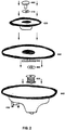
- Fig. 2 is a diagram illustrating a contactless horn and sound device with attached electronic integrated circuit module according to an exemplary embodiment.
- the contactless horn and housing 400 comprises an electromagnet 410 which may magnetically manipulate (i.e., repel and attract) the metal plate 490 secured to the bottom diaphragm 430 of the contactless horn to create a tone in accordance with the selected frequency generated by the signal generator 200.
- the electromagnet 410 may be comprised of a coil, preferably a copper coil that is 20 gauge or higher (i.e., smaller in diameter), wrapped around a metal (e.g., steel, iron, or other magnetizable metal) bolt.
- the gauge of the copper coil may be higher or lower depending on a variety of factors, such as power, weight, etc.
- the output of the output driver 300 is electrically connected to the electromagnet 410 via the IC connection interface 450, which is preferably positioned on the exterior of the base 440.
- the base 440 may be constructed using a lightweight plastic, a lightweight metal, or another suitable material.
- Top diaphragm 420 and bottom diaphragm 430 may be secured together using bolt 460 and washers 470 and 480 and the bottom diaphragm 430 may then be secured to the base 440 along the rim of the base 440, thereby allowing the free movement of the center portion of the diaphragms 420 and 430 so as to produce the preconfigured frequency sound.
- the signal generator 200 may be used to generate multiple pitches, tones or notes simultaneously by modifying the interval at which different frequencies are generated to create different tones.
- the electromagnet 410 may be switched from operating at 300 Hz to 500 Hz every millisecond, so as to create a low and high tone from a single device. This provides an advantage over related art horns that use two separate horns to create two different tones.
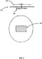
- Fig. 3 is a diagram illustrating the side view and bottom view of the diaphragm portion of a contactless horn and sound device according to an exemplary embodiment.
- the separation, or "air gap” preferably comprises a distance between 1,27 to 6,35 mm (0.05 to 0.25 inches), with a tolerance of +/- 1,27 mm (0.05 inches).
- this separation or "air gap” may be adjusted as needed based on the desired application.
- the contactless horn device may be modified to play additional frequency tones by adding additional signal generators 200 and additional sequencers 100 to the electronic IC module and configuring them according to the present teachings.
- Fig. 4 is a diagram illustrating a contactless horn and sound device that interacts with a vehicle system according to an exemplary embodiment that generates multiple tones based on input received from the vehicle system.
- sound device 400 may interface with a vehicle's motherboard 410 or other similar component that receives data signals from various vehicle triggers, switches, and external sensors 420 indicating the status of the vehicle, such as, without limitation, the Intelligent Power Distribution Module (IPDM) found in Nissan vehicles.
- IPDM Intelligent Power Distribution Module
- Sound device 400 may produce different tones, pitches, frequencies, sounds and/or intervals of sounds based on data received from the vehicle motherboard 410.
- one or more of the various sensors 420 may send a signal 415 indicating the speed of the vehicle to the vehicle's motherboard 410, which includes one or more vehicle central processing units (CPUs) 411.
- the vehicle CPU 411 may send a signal 405 to the sound device 400 that is used to control the output of signal generators 200 to output a particular tone, pitch, frequency, sound, or sound interval, as discussed above.
- Data signal 405 or 415 may be received by receiver 401 of the sound device 400, and provided as input to a CPU 402 to control mechanical parts 403 of the sound device 400 to generate a particular sound.
- Sound device 400 may also include a transmitter 404 that provides feedback to the vehicle CPU 411 or the various sensors 420 indicating the status of the sound device and the pitches, tones, frequencies, or sounds it has produced.
- the contactless horn and sound device of the exemplary embodiment may modify the pitch, frequency, or tone produced based on a variety of inputs provided from the various sensors 420.
- the sound device 400 produces a louder (that is, higher amplitude) sound if the vehicle is moving at a high rate of speed than if the vehicle is moving slowly or stopped.
- the sound device 400 may also produce different sounds in response to a signal that the vehicle's anti-theft alarm has been triggered, or to announce that the driver has locked or unlocked the vehicle.
- the sound device 400 of the exemplary embodiment may also produce multiple alarm sounds depending how the alarm was triggered.
- the sound device 400 may produce a softer tone or more delayed sound interval, as compared to an alarm that is triggered by someone or something smashing the vehicle's windshield or window.
- the pitches, frequencies, tones and sounds generated by the sound device 400 may also be tailored to each vehicle manufacturer and/or model.
- Transmitter 404 may also be used to notify the driver of various conditions relating to the vehicle. For example, when the vehicle's alarm is triggered, in addition to generating a particular sound according to the type of alarm triggered, the sound device 400 may cause transmitter 404 to notify the driver that the alarm has been triggered. For example, transmitter 404 may notify the driver of the alarm via text message, email, or other electronic notification means.
- many vehicles include proximity sensors that detect when the driver is within a certain distance of the vehicle, for example, to unlock the doors of the vehicle as the driver approaches.
- Sound device 400 may receive a signal from these proximity sensors to alert the driver that the vehicle doors are unlocked when the driver is a certain distance away from the vehicle.
- the tone, pitch, frequency, and volume of the sound may be configured depending on the driver's distance from the vehicle.
- Sound device 400 may generate various sounds depending on various other sensors 420 in accordance with the exemplary embodiment.
- many vehicles include sensors that detect proximity to other vehicles to alert the driver of a potential impact, (e.g., alerting the driver attempting to change lanes of other vehicles in the driver's blind spot).
- such sensors 420 may send signals to sound device 400 indicating the proximity of an object, and the size or type of object, based on which the sound the signal generator 200 will cause the sound device 400 to produce an appropriate sound.
- the sound device 400 of the vehicle in the blind spot may generate a sound in response to a signal indicating that the vehicle changing lanes approaches within a specified distance of the vehicle.
- the sound device 400 may generate a softer sound to warn the pedestrian. If a fast-moving vehicle is detected, the sound device 400 may generate a louder sound to warn the driver of the fast moving vehicle. If an animal, such as a deer, is detected, the sound device 500 may generate a sound having a frequency that will deter the animal and potentially avoid an impact
- the sound device 400 may be connected to the vehicle CPU 411 or the vehicle's sensors 420 wirelessly.
- wireless technologies e.g., Bluetooth
- Using a wireless connection between these devices would eliminate the need for wiring material and switches, reducing cost and weight and simplifying manufacturing.
- the vehicle sensors 420 or transmitter 404 may also send a wireless signal that is received by sound devices of surrounding vehicles within a certain radius.
- the sound devices in the surrounding vehicles may generate sound having a pitch, frequency, tone, and/or volume that depends on the type of signal received from the vehicle sensors 420. For example, sound devices of vehicles closer to the vehicle whose sensors 420 transmitted the wireless signal may generate a louder sound than sound devices in vehicles that are further away.
- the frequency or tone of the generated sound may depend on the type of vehicle from which the signal originates. For example, vehicle sensors 420 located on a truck may cause a deeper and/or louder sound to be produced in surrounding vehicles, as compared to vehicles sensors 420 located on a smaller car.
- the sound generated by the sound devices of the surrounding vehicles may be generated within the surrounding vehicle, e.g., through the speaker system of the surrounding vehicle, or external of the surrounding vehicle, e.g., by the horn of the surrounding vehicle.
- the sound devices of the surrounding vehicles may be generated within the surrounding vehicle, e.g., through the speaker system of the surrounding vehicle, or external of the surrounding vehicle, e.g., by the horn of the surrounding vehicle.
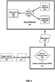
- Fig. 5 is a diagram illustrating a contactless horn and sound device according to an exemplary embodiment that may communicate with surrounding vehicles to cause a sound to be generated by a horn or audio system in the surrounding vehicles.
- the driver activates the contactless horn trigger of the exemplary embodiment, which may be located on the vehicle steering wheel or other location.
- a signal indicating that the horn trigger has been activated may be sent to the vehicle CPU or Controller Area Network (CAN) bus wirelessly or via wired connection.
- CAN Controller Area Network
- a signal indicating that the horn trigger has been activated may be sent directly to the contactless horn.
- the vehicle CPU or CAN bus may send a signal to the contactless horn indicating one or more current operating states of the vehicle.
- the vehicle CPU or CAN bus may transmit a signal indicating the vehicle speed, time of day, vehicle location, etc.
- the contactless horn may process the signal received in step 603 to determine the appropriate outcome corresponding to the received signal.
- the contactless horn may transmit a signal to the vehicle CPU, CAN bus, or vehicle-to-vehicle communication system indicating operational instructions for a horn or audio system in surrounding vehicles.
- the vehicle-to-vehicle communication system may transmit operational instructions to vehicles located within a specified radius of the vehicle.
- the CPU, CAN bus, or vehicle-to-vehicle communication system of the surrounding vehicles may transmit the received operational instructions to the respective contactless horns of the surrounding vehicles.
- the contactless horns of the surrounding vehicles may process the received operational instructions to determine the appropriate output.
- the contactless horns of the surrounding vehicles may transmit the appropriate operational instructions to their respective CPU or CAN bus.
- the CPU or CAN bus of the surrounding vehicle may transmit operational signals to an internal sound device or audio system to generate sound according to the operational signal.
- Fig. 6 is a circuit diagram illustrating an electronic circuit for a contactless horn and sound device according to an exemplary embodiment.
- the exemplary embodiment depicted in Fig. 6 may include a power input stage 701, a voltage regulator 702, a microprocessor 703, resistors 704 and 705, transistor 706 and output stage 707.
- power is input to the contactless horn circuit at power input stage 701.
- the input power is received as an input at voltage regulator 702, which modifies the voltage level of the input power to an appropriate voltage for microprocessor 703.
- Voltage regulator 702 outputs the modified voltage to an input pin of microprocessor 703.
- resistor 704 Also connected to the same input pin of microprocessor 703 is resistor 704, which is also in parallel with voltage regulator 702.
- the frequency of the signal output by the microprocessor 703 is controlled by the resistance value of resistor 704.
- Resistor 705 is connected in parallel with resistor 704, and the resistance value of resistor 705 controls the duty cycle of the signal output by the microprocessor 703.
- microprocessor outputs a signal having a particular frequency and duty cycle.
- the output signal of microprocessor 703 is received as input to transistor 706.
- transistor 706 may be a MOSFET transistor.
- Transistor 706 controls the signal output from microprocessor 703 and provides the output signal to output stage 706, which generates a sound through the car horn based on the received output signal.
Landscapes
- Physics & Mathematics (AREA)
- Engineering & Computer Science (AREA)
- Acoustics & Sound (AREA)
- Multimedia (AREA)
- Signal Processing (AREA)
- Mechanical Engineering (AREA)
- Electromagnetism (AREA)
- Details Of Audible-Bandwidth Transducers (AREA)
- Fittings On The Vehicle Exterior For Carrying Loads, And Devices For Holding Or Mounting Articles (AREA)
- Transducers For Ultrasonic Waves (AREA)
Applications Claiming Priority (1)
| Application Number | Priority Date | Filing Date | Title |
|---|---|---|---|
| PCT/US2014/036416 WO2015167572A1 (en) | 2014-05-01 | 2014-05-01 | Electronic contactless horn and sound device |
Publications (3)
| Publication Number | Publication Date |
|---|---|
| EP3105081A1 EP3105081A1 (en) | 2016-12-21 |
| EP3105081A4 EP3105081A4 (en) | 2017-10-04 |
| EP3105081B1 true EP3105081B1 (en) | 2021-08-25 |
Family
ID=54359105
Family Applications (1)
| Application Number | Title | Priority Date | Filing Date |
|---|---|---|---|
| EP14890641.5A Active EP3105081B1 (en) | 2014-05-01 | 2014-05-01 | Electronic contactless horn and sound device |
Country Status (14)
| Country | Link |
|---|---|
| US (1) | US10086653B2 (enExample) |
| EP (1) | EP3105081B1 (enExample) |
| JP (1) | JP6599978B2 (enExample) |
| KR (1) | KR101931865B1 (enExample) |
| CN (1) | CN106232426B (enExample) |
| AU (2) | AU2014392641A1 (enExample) |
| BR (1) | BR112016025639A8 (enExample) |
| CA (1) | CA2947244C (enExample) |
| IL (1) | IL248291B (enExample) |
| MX (1) | MX363304B (enExample) |
| MY (1) | MY191312A (enExample) |
| SG (1) | SG11201608840SA (enExample) |
| WO (1) | WO2015167572A1 (enExample) |
| ZA (1) | ZA201606266B (enExample) |
Families Citing this family (5)
| Publication number | Priority date | Publication date | Assignee | Title |
|---|---|---|---|---|
| JP5916931B1 (ja) | 2015-07-28 | 2016-05-11 | 衆智達技研株式会社 | 電子式警音器 |
| CN109311421B (zh) * | 2016-05-11 | 2022-04-15 | 万喻 | 一种利用总线控制多用途喇叭的方法和电路 |
| JP6493929B2 (ja) | 2017-03-01 | 2019-04-03 | 株式会社今仙電機製作所 | 電子式警音器 |
| US11308930B2 (en) | 2017-11-09 | 2022-04-19 | Imasen Electric Industrial Co., Ltd. | Electronic horn |
| CN114785333A (zh) * | 2022-01-14 | 2022-07-22 | 深圳地铁运营集团有限公司 | 一种符合sil4安全等级的故障安全的无触点输出电路 |
Citations (1)
| Publication number | Priority date | Publication date | Assignee | Title |
|---|---|---|---|---|
| US20100164695A1 (en) * | 2008-12-25 | 2010-07-01 | Choi Sang-Kyu | Electronic Disk-Type Horn And Horn Using Photointerrupter |
Family Cites Families (39)
| Publication number | Priority date | Publication date | Assignee | Title |
|---|---|---|---|---|
| SE435777B (sv) | 1979-01-29 | 1984-10-15 | Ibuki Kogyo Co Ltd | Elektriskt horn |
| FR2519493A1 (fr) | 1981-12-31 | 1983-07-08 | Agence Centrale De Services | Systeme de commande d'une sirene |
| US4540975A (en) * | 1982-04-06 | 1985-09-10 | Marukokeihouki Co., Ltd. | Electric horns |
| CN88201308U (zh) | 1988-02-01 | 1988-08-24 | 陈颂华 | 多音无触点电子喇叭 |
| US5012221A (en) | 1989-03-24 | 1991-04-30 | Siren Sounds, Inc. | Emergency vehicle audible warning system and method |
| IT1228767B (it) * | 1989-03-29 | 1991-07-03 | Electronsystem Spa | Avvisatore acustico per autoveicoli pilotato elettronicamente. |
| US5841367A (en) * | 1990-11-07 | 1998-11-24 | Giovanni; Caico | Electronic equipment for prevention of collisions between vehicles |
| JPH04114300U (ja) * | 1991-03-22 | 1992-10-07 | テイーデイーケイ株式会社 | 電磁型電気音響変換器 |
| US5293149A (en) * | 1991-04-12 | 1994-03-08 | Sparton Corporation | Vehicle horn with electronic solid state energizing circuit |
| US8604932B2 (en) * | 1992-05-05 | 2013-12-10 | American Vehicular Sciences, LLC | Driver fatigue monitoring system and method |
| JPH09114467A (ja) | 1995-10-13 | 1997-05-02 | Mitsubishi Automob Eng Co Ltd | ブザー装置 |
| DE19730791A1 (de) | 1997-07-18 | 1999-01-21 | Bosch Gmbh Robert | Verfahren zur Erstellung von Warnhinweisen für Fahrer eines Kraftfahrzeugs und Verkehrswarngerät |
| CN1170896A (zh) | 1997-07-29 | 1998-01-21 | 哈尔滨电子应用技术研究所 | 一种单片机控制发声稳频电喇叭的方法及装置 |
| JP2002354853A (ja) | 1997-08-04 | 2002-12-06 | Seiko Epson Corp | アクチュエータ、およびそれを用いた時計並びに報知装置 |
| JPH11208370A (ja) * | 1998-01-23 | 1999-08-03 | Nissan Motor Co Ltd | 車両走行支援装置 |
| DE19847013A1 (de) | 1998-10-13 | 2000-04-20 | Bosch Gmbh Robert | Einparkhilfesystem |
| EP1082872A1 (en) | 1998-11-19 | 2001-03-14 | Microtech Corporation | Electric-acoustic transducer having moving magnet and transducing method thereof |
| US7099751B2 (en) | 2002-10-01 | 2006-08-29 | Electronic Data Systems Corporation | Drive-by-wireless vehicle control |
| JP2004133719A (ja) | 2002-10-11 | 2004-04-30 | Renesas Technology Corp | マイクロコンピュータ |
| CN2695295Y (zh) | 2003-10-31 | 2005-04-27 | 林文骅 | 车辆无触点电喇叭 |
| CN2712730Y (zh) | 2004-05-20 | 2005-07-27 | 薛白 | 汽车防撞装置 |
| US8629800B2 (en) | 2004-09-30 | 2014-01-14 | The Boeing Company | Ground vehicle collision prevention systems and methods |
| US20060287829A1 (en) | 2005-06-15 | 2006-12-21 | Dimitri Pashko-Paschenko | Object proximity warning system |
| JP4920431B2 (ja) * | 2007-01-23 | 2012-04-18 | 本田技研工業株式会社 | 衝突被害軽減システム |
| US8248223B2 (en) | 2008-08-25 | 2012-08-21 | Neeraj Periwal | Speed reporting for providing conditional driver treatment |
| WO2010035123A2 (en) | 2008-09-26 | 2010-04-01 | Gerres, Stephan | An electronic horn for a vehicle |
| JP2010143247A (ja) * | 2008-12-16 | 2010-07-01 | Nippon Seiki Co Ltd | 車両用報知装置 |
| JP2011213228A (ja) | 2010-03-31 | 2011-10-27 | Sumitomo Electric Ind Ltd | 電動自動車の警報音発生装置 |
| US8217767B2 (en) | 2010-06-09 | 2012-07-10 | Denso Corporation | Vehicle presence notification apparatus |
| JP5206762B2 (ja) | 2010-10-19 | 2013-06-12 | 株式会社デンソー | 車両用警報装置 |
| JP2012101608A (ja) * | 2010-11-08 | 2012-05-31 | Maruko Keihoki Co Ltd | 車両接近通報音発生装置 |
| WO2012081883A2 (en) * | 2010-12-13 | 2012-06-21 | Samsung Electronics Co., Ltd. | Information providing apparatus and method for vehicles |
| US8892333B2 (en) | 2011-03-09 | 2014-11-18 | Denso Corporation | Vehicle rank distinction device for vehicle and travel sound generator device |
| JP5853442B2 (ja) * | 2011-07-01 | 2016-02-09 | 日産自動車株式会社 | 警報音生成装置 |
| JP5344016B2 (ja) | 2011-09-27 | 2013-11-20 | 株式会社デンソー | 車両存在通報装置 |
| FR2980615B1 (fr) | 2011-09-28 | 2013-09-27 | Delphi Tech Inc | Sirene comportant un systeme de connexion ameliore |
| CN104470763B (zh) | 2012-05-22 | 2017-02-22 | Trw汽车美国有限责任公司 | 用于检测车辆/行人撞击的混合方法和装置 |
| CN204066089U (zh) * | 2014-07-15 | 2014-12-31 | 苏州技杰软件有限公司 | 非接触式音频验证装置 |
| JP5850124B2 (ja) * | 2014-11-14 | 2016-02-03 | 浜名湖電装株式会社 | 車両接近通報装置 |
-
2014
- 2014-05-01 BR BR112016025639A patent/BR112016025639A8/pt not_active Application Discontinuation
- 2014-05-01 US US15/301,727 patent/US10086653B2/en active Active
- 2014-05-01 AU AU2014392641A patent/AU2014392641A1/en not_active Abandoned
- 2014-05-01 MX MX2016012617A patent/MX363304B/es unknown
- 2014-05-01 WO PCT/US2014/036416 patent/WO2015167572A1/en not_active Ceased
- 2014-05-01 EP EP14890641.5A patent/EP3105081B1/en active Active
- 2014-05-01 CN CN201480078087.2A patent/CN106232426B/zh active Active
- 2014-05-01 MY MYPI2016703693A patent/MY191312A/en unknown
- 2014-05-01 JP JP2017509584A patent/JP6599978B2/ja active Active
- 2014-05-01 SG SG11201608840SA patent/SG11201608840SA/en unknown
- 2014-05-01 KR KR1020167030488A patent/KR101931865B1/ko active Active
- 2014-05-01 CA CA2947244A patent/CA2947244C/en not_active Expired - Fee Related
-
2016
- 2016-09-09 ZA ZA2016/06266A patent/ZA201606266B/en unknown
- 2016-10-10 IL IL248291A patent/IL248291B/en active IP Right Grant
-
2018
- 2018-07-04 AU AU2018204868A patent/AU2018204868A1/en not_active Abandoned
Patent Citations (1)
| Publication number | Priority date | Publication date | Assignee | Title |
|---|---|---|---|---|
| US20100164695A1 (en) * | 2008-12-25 | 2010-07-01 | Choi Sang-Kyu | Electronic Disk-Type Horn And Horn Using Photointerrupter |
Also Published As
| Publication number | Publication date |
|---|---|
| CA2947244C (en) | 2021-04-13 |
| AU2018204868A1 (en) | 2018-07-19 |
| ZA201606266B (en) | 2018-05-30 |
| MX363304B (es) | 2019-03-20 |
| IL248291B (en) | 2020-09-30 |
| US10086653B2 (en) | 2018-10-02 |
| JP2017516158A (ja) | 2017-06-15 |
| KR20170003551A (ko) | 2017-01-09 |
| KR101931865B1 (ko) | 2018-12-21 |
| MY191312A (en) | 2022-06-15 |
| BR112016025639A8 (pt) | 2021-10-19 |
| JP6599978B2 (ja) | 2019-10-30 |
| US20170120812A1 (en) | 2017-05-04 |
| MX2016012617A (es) | 2017-04-06 |
| WO2015167572A1 (en) | 2015-11-05 |
| CN106232426A (zh) | 2016-12-14 |
| EP3105081A1 (en) | 2016-12-21 |
| EP3105081A4 (en) | 2017-10-04 |
| IL248291A0 (en) | 2016-11-30 |
| BR112016025639A2 (enExample) | 2017-08-15 |
| CN106232426B (zh) | 2019-07-05 |
| CA2947244A1 (en) | 2015-11-05 |
| SG11201608840SA (en) | 2016-11-29 |
| AU2014392641A1 (en) | 2016-09-29 |
Similar Documents
| Publication | Publication Date | Title |
|---|---|---|
| AU2018204868A1 (en) | Electronic contactless horn and sound device | |
| EP2709891B1 (en) | Method for supporting a driver using a portable device in a vehicle | |
| US11472336B2 (en) | Electronically operated forward and reverse warning / sound signalling device | |
| CN101531177A (zh) | 车用防盗报警器 | |
| JP2015134543A (ja) | 断線検知装置 | |
| JP6343922B2 (ja) | ホーン制御装置 | |
| US20190184892A1 (en) | Vehicle signaling apparatus | |
| JP2019023745A (ja) | 非接触型電子音響デバイス | |
| HK1226701A1 (en) | Electronic contactless horn and sound device | |
| HK1226701B (zh) | 电子非接触式喇叭和声音装置 | |
| JP2010044632A (ja) | 車両用警報装置 | |
| US7786848B2 (en) | Vehicle security systems | |
| KR101895187B1 (ko) | 초지향성 스피커를 이용한 경고음 출력 장치 및 방법 | |
| JP5850124B2 (ja) | 車両接近通報装置 | |
| JP2012101608A (ja) | 車両接近通報音発生装置 | |
| KR102041779B1 (ko) | 차량용 경적장치 | |
| WO2014151827A2 (en) | Electronic contactless horn and sound device | |
| JP6002881B2 (ja) | 車両用警報装置 | |
| JP5757321B2 (ja) | 車両用警報装置 | |
| JP2020084563A (ja) | 交通規制注意喚起システム | |
| JPS5992227A (ja) | 車載警報音発生装置 | |
| JP2024142887A (ja) | 報知システム、報知方法、及びコンピュータプログラム | |
| CN107042793B (zh) | 用于车辆的模拟鸣笛系统及应用于车辆的鸣笛方法 | |
| JP2015027878A (ja) | 車両接近通報装置 | |
| JP5500657B2 (ja) | ホーン受信装置、ホーンシステム、ホーン受信装置の駆動方法およびプログラム |
Legal Events
| Date | Code | Title | Description |
|---|---|---|---|
| PUAI | Public reference made under article 153(3) epc to a published international application that has entered the european phase |
Free format text: ORIGINAL CODE: 0009012 |
|
| STAA | Information on the status of an ep patent application or granted ep patent |
Free format text: STATUS: REQUEST FOR EXAMINATION WAS MADE |
|
| 17P | Request for examination filed |
Effective date: 20160912 |
|
| AK | Designated contracting states |
Kind code of ref document: A1 Designated state(s): AL AT BE BG CH CY CZ DE DK EE ES FI FR GB GR HR HU IE IS IT LI LT LU LV MC MK MT NL NO PL PT RO RS SE SI SK SM TR |
|
| AX | Request for extension of the european patent |
Extension state: BA ME |
|
| DAX | Request for extension of the european patent (deleted) | ||
| A4 | Supplementary search report drawn up and despatched |
Effective date: 20170906 |
|
| RIC1 | Information provided on ipc code assigned before grant |
Ipc: B60Q 5/00 20060101AFI20170831BHEP Ipc: G10K 9/12 20060101ALI20170831BHEP Ipc: G10K 9/13 20060101ALI20170831BHEP |
|
| STAA | Information on the status of an ep patent application or granted ep patent |
Free format text: STATUS: EXAMINATION IS IN PROGRESS |
|
| 17Q | First examination report despatched |
Effective date: 20190605 |
|
| GRAP | Despatch of communication of intention to grant a patent |
Free format text: ORIGINAL CODE: EPIDOSNIGR1 |
|
| STAA | Information on the status of an ep patent application or granted ep patent |
Free format text: STATUS: GRANT OF PATENT IS INTENDED |
|
| INTG | Intention to grant announced |
Effective date: 20210401 |
|
| GRAS | Grant fee paid |
Free format text: ORIGINAL CODE: EPIDOSNIGR3 |
|
| GRAA | (expected) grant |
Free format text: ORIGINAL CODE: 0009210 |
|
| STAA | Information on the status of an ep patent application or granted ep patent |
Free format text: STATUS: THE PATENT HAS BEEN GRANTED |
|
| AK | Designated contracting states |
Kind code of ref document: B1 Designated state(s): AL AT BE BG CH CY CZ DE DK EE ES FI FR GB GR HR HU IE IS IT LI LT LU LV MC MK MT NL NO PL PT RO RS SE SI SK SM TR |
|
| REG | Reference to a national code |
Ref country code: CH Ref legal event code: EP |
|
| REG | Reference to a national code |
Ref country code: IE Ref legal event code: FG4D Ref country code: AT Ref legal event code: REF Ref document number: 1423476 Country of ref document: AT Kind code of ref document: T Effective date: 20210915 |
|
| REG | Reference to a national code |
Ref country code: DE Ref legal event code: R096 Ref document number: 602014079762 Country of ref document: DE |
|
| REG | Reference to a national code |
Ref country code: LT Ref legal event code: MG9D |
|
| REG | Reference to a national code |
Ref country code: NL Ref legal event code: MP Effective date: 20210825 |
|
| REG | Reference to a national code |
Ref country code: AT Ref legal event code: MK05 Ref document number: 1423476 Country of ref document: AT Kind code of ref document: T Effective date: 20210825 |
|
| PG25 | Lapsed in a contracting state [announced via postgrant information from national office to epo] |
Ref country code: BG Free format text: LAPSE BECAUSE OF FAILURE TO SUBMIT A TRANSLATION OF THE DESCRIPTION OR TO PAY THE FEE WITHIN THE PRESCRIBED TIME-LIMIT Effective date: 20211125 Ref country code: AT Free format text: LAPSE BECAUSE OF FAILURE TO SUBMIT A TRANSLATION OF THE DESCRIPTION OR TO PAY THE FEE WITHIN THE PRESCRIBED TIME-LIMIT Effective date: 20210825 Ref country code: LT Free format text: LAPSE BECAUSE OF FAILURE TO SUBMIT A TRANSLATION OF THE DESCRIPTION OR TO PAY THE FEE WITHIN THE PRESCRIBED TIME-LIMIT Effective date: 20210825 Ref country code: NO Free format text: LAPSE BECAUSE OF FAILURE TO SUBMIT A TRANSLATION OF THE DESCRIPTION OR TO PAY THE FEE WITHIN THE PRESCRIBED TIME-LIMIT Effective date: 20211125 Ref country code: PT Free format text: LAPSE BECAUSE OF FAILURE TO SUBMIT A TRANSLATION OF THE DESCRIPTION OR TO PAY THE FEE WITHIN THE PRESCRIBED TIME-LIMIT Effective date: 20211227 Ref country code: ES Free format text: LAPSE BECAUSE OF FAILURE TO SUBMIT A TRANSLATION OF THE DESCRIPTION OR TO PAY THE FEE WITHIN THE PRESCRIBED TIME-LIMIT Effective date: 20210825 Ref country code: FI Free format text: LAPSE BECAUSE OF FAILURE TO SUBMIT A TRANSLATION OF THE DESCRIPTION OR TO PAY THE FEE WITHIN THE PRESCRIBED TIME-LIMIT Effective date: 20210825 Ref country code: HR Free format text: LAPSE BECAUSE OF FAILURE TO SUBMIT A TRANSLATION OF THE DESCRIPTION OR TO PAY THE FEE WITHIN THE PRESCRIBED TIME-LIMIT Effective date: 20210825 Ref country code: SE Free format text: LAPSE BECAUSE OF FAILURE TO SUBMIT A TRANSLATION OF THE DESCRIPTION OR TO PAY THE FEE WITHIN THE PRESCRIBED TIME-LIMIT Effective date: 20210825 Ref country code: RS Free format text: LAPSE BECAUSE OF FAILURE TO SUBMIT A TRANSLATION OF THE DESCRIPTION OR TO PAY THE FEE WITHIN THE PRESCRIBED TIME-LIMIT Effective date: 20210825 |
|
| PG25 | Lapsed in a contracting state [announced via postgrant information from national office to epo] |
Ref country code: PL Free format text: LAPSE BECAUSE OF FAILURE TO SUBMIT A TRANSLATION OF THE DESCRIPTION OR TO PAY THE FEE WITHIN THE PRESCRIBED TIME-LIMIT Effective date: 20210825 Ref country code: LV Free format text: LAPSE BECAUSE OF FAILURE TO SUBMIT A TRANSLATION OF THE DESCRIPTION OR TO PAY THE FEE WITHIN THE PRESCRIBED TIME-LIMIT Effective date: 20210825 Ref country code: GR Free format text: LAPSE BECAUSE OF FAILURE TO SUBMIT A TRANSLATION OF THE DESCRIPTION OR TO PAY THE FEE WITHIN THE PRESCRIBED TIME-LIMIT Effective date: 20211126 |
|
| PG25 | Lapsed in a contracting state [announced via postgrant information from national office to epo] |
Ref country code: NL Free format text: LAPSE BECAUSE OF FAILURE TO SUBMIT A TRANSLATION OF THE DESCRIPTION OR TO PAY THE FEE WITHIN THE PRESCRIBED TIME-LIMIT Effective date: 20210825 |
|
| PG25 | Lapsed in a contracting state [announced via postgrant information from national office to epo] |
Ref country code: DK Free format text: LAPSE BECAUSE OF FAILURE TO SUBMIT A TRANSLATION OF THE DESCRIPTION OR TO PAY THE FEE WITHIN THE PRESCRIBED TIME-LIMIT Effective date: 20210825 |
|
| REG | Reference to a national code |
Ref country code: DE Ref legal event code: R097 Ref document number: 602014079762 Country of ref document: DE |
|
| PG25 | Lapsed in a contracting state [announced via postgrant information from national office to epo] |
Ref country code: SM Free format text: LAPSE BECAUSE OF FAILURE TO SUBMIT A TRANSLATION OF THE DESCRIPTION OR TO PAY THE FEE WITHIN THE PRESCRIBED TIME-LIMIT Effective date: 20210825 Ref country code: SK Free format text: LAPSE BECAUSE OF FAILURE TO SUBMIT A TRANSLATION OF THE DESCRIPTION OR TO PAY THE FEE WITHIN THE PRESCRIBED TIME-LIMIT Effective date: 20210825 Ref country code: RO Free format text: LAPSE BECAUSE OF FAILURE TO SUBMIT A TRANSLATION OF THE DESCRIPTION OR TO PAY THE FEE WITHIN THE PRESCRIBED TIME-LIMIT Effective date: 20210825 Ref country code: EE Free format text: LAPSE BECAUSE OF FAILURE TO SUBMIT A TRANSLATION OF THE DESCRIPTION OR TO PAY THE FEE WITHIN THE PRESCRIBED TIME-LIMIT Effective date: 20210825 Ref country code: CZ Free format text: LAPSE BECAUSE OF FAILURE TO SUBMIT A TRANSLATION OF THE DESCRIPTION OR TO PAY THE FEE WITHIN THE PRESCRIBED TIME-LIMIT Effective date: 20210825 Ref country code: AL Free format text: LAPSE BECAUSE OF FAILURE TO SUBMIT A TRANSLATION OF THE DESCRIPTION OR TO PAY THE FEE WITHIN THE PRESCRIBED TIME-LIMIT Effective date: 20210825 |
|
| PLBE | No opposition filed within time limit |
Free format text: ORIGINAL CODE: 0009261 |
|
| STAA | Information on the status of an ep patent application or granted ep patent |
Free format text: STATUS: NO OPPOSITION FILED WITHIN TIME LIMIT |
|
| 26N | No opposition filed |
Effective date: 20220527 |
|
| PG25 | Lapsed in a contracting state [announced via postgrant information from national office to epo] |
Ref country code: SI Free format text: LAPSE BECAUSE OF FAILURE TO SUBMIT A TRANSLATION OF THE DESCRIPTION OR TO PAY THE FEE WITHIN THE PRESCRIBED TIME-LIMIT Effective date: 20210825 |
|
| REG | Reference to a national code |
Ref country code: DE Ref legal event code: R082 Ref document number: 602014079762 Country of ref document: DE Representative=s name: ALPSPITZ IP ALLGAYER UND PARTNER PATENTANWAELT, DE |
|
| PG25 | Lapsed in a contracting state [announced via postgrant information from national office to epo] |
Ref country code: HU Free format text: LAPSE BECAUSE OF FAILURE TO SUBMIT A TRANSLATION OF THE DESCRIPTION OR TO PAY THE FEE WITHIN THE PRESCRIBED TIME-LIMIT; INVALID AB INITIO Effective date: 20140501 |
|
| PG25 | Lapsed in a contracting state [announced via postgrant information from national office to epo] |
Ref country code: MK Free format text: LAPSE BECAUSE OF FAILURE TO SUBMIT A TRANSLATION OF THE DESCRIPTION OR TO PAY THE FEE WITHIN THE PRESCRIBED TIME-LIMIT Effective date: 20210825 Ref country code: CY Free format text: LAPSE BECAUSE OF FAILURE TO SUBMIT A TRANSLATION OF THE DESCRIPTION OR TO PAY THE FEE WITHIN THE PRESCRIBED TIME-LIMIT Effective date: 20210825 |
|
| PGFP | Annual fee paid to national office [announced via postgrant information from national office to epo] |
Ref country code: LU Payment date: 20240521 Year of fee payment: 11 |
|
| PGFP | Annual fee paid to national office [announced via postgrant information from national office to epo] |
Ref country code: IE Payment date: 20240517 Year of fee payment: 11 |
|
| PGFP | Annual fee paid to national office [announced via postgrant information from national office to epo] |
Ref country code: MC Payment date: 20240521 Year of fee payment: 11 |
|
| PGFP | Annual fee paid to national office [announced via postgrant information from national office to epo] |
Ref country code: CH Payment date: 20240602 Year of fee payment: 11 |
|
| PGFP | Annual fee paid to national office [announced via postgrant information from national office to epo] |
Ref country code: FR Payment date: 20240522 Year of fee payment: 11 |
|
| PGFP | Annual fee paid to national office [announced via postgrant information from national office to epo] |
Ref country code: BE Payment date: 20240521 Year of fee payment: 11 |
|
| PG25 | Lapsed in a contracting state [announced via postgrant information from national office to epo] |
Ref country code: MT Free format text: LAPSE BECAUSE OF FAILURE TO SUBMIT A TRANSLATION OF THE DESCRIPTION OR TO PAY THE FEE WITHIN THE PRESCRIBED TIME-LIMIT Effective date: 20210825 |
|
| PGFP | Annual fee paid to national office [announced via postgrant information from national office to epo] |
Ref country code: DE Payment date: 20250519 Year of fee payment: 12 |
|
| PGFP | Annual fee paid to national office [announced via postgrant information from national office to epo] |
Ref country code: GB Payment date: 20250522 Year of fee payment: 12 |
|
| PGFP | Annual fee paid to national office [announced via postgrant information from national office to epo] |
Ref country code: IT Payment date: 20250530 Year of fee payment: 12 |
|
| PG25 | Lapsed in a contracting state [announced via postgrant information from national office to epo] |
Ref country code: TR Free format text: LAPSE BECAUSE OF FAILURE TO SUBMIT A TRANSLATION OF THE DESCRIPTION OR TO PAY THE FEE WITHIN THE PRESCRIBED TIME-LIMIT Effective date: 20210825 |
|
| REG | Reference to a national code |
Ref country code: CH Ref legal event code: H13 Free format text: ST27 STATUS EVENT CODE: U-0-0-H10-H13 (AS PROVIDED BY THE NATIONAL OFFICE) Effective date: 20251223 |
|
| PG25 | Lapsed in a contracting state [announced via postgrant information from national office to epo] |
Ref country code: LU Free format text: LAPSE BECAUSE OF NON-PAYMENT OF DUE FEES Effective date: 20250501 |
|
| PG25 | Lapsed in a contracting state [announced via postgrant information from national office to epo] |
Ref country code: CH Free format text: LAPSE BECAUSE OF NON-PAYMENT OF DUE FEES Effective date: 20250531 |
|
| PG25 | Lapsed in a contracting state [announced via postgrant information from national office to epo] |
Ref country code: MC Free format text: LAPSE BECAUSE OF NON-PAYMENT OF DUE FEES Effective date: 20250602 |