EP3104087A1 - Unité intérieure pour climatiseur - Google Patents
Unité intérieure pour climatiseur Download PDFInfo
- Publication number
- EP3104087A1 EP3104087A1 EP15868661.8A EP15868661A EP3104087A1 EP 3104087 A1 EP3104087 A1 EP 3104087A1 EP 15868661 A EP15868661 A EP 15868661A EP 3104087 A1 EP3104087 A1 EP 3104087A1
- Authority
- EP
- European Patent Office
- Prior art keywords
- air
- support arms
- heat exchange
- exchange element
- fan
- Prior art date
- Legal status (The legal status is an assumption and is not a legal conclusion. Google has not performed a legal analysis and makes no representation as to the accuracy of the status listed.)
- Granted
Links
- 238000004378 air conditioning Methods 0.000 claims abstract description 54
- 238000004140 cleaning Methods 0.000 claims description 14
- 230000005484 gravity Effects 0.000 claims description 11
- 239000000428 dust Substances 0.000 claims description 6
- 239000003507 refrigerant Substances 0.000 claims description 4
- 238000010586 diagram Methods 0.000 description 8
- 239000011347 resin Substances 0.000 description 4
- 229920005989 resin Polymers 0.000 description 4
- 230000002093 peripheral effect Effects 0.000 description 3
- 230000000694 effects Effects 0.000 description 2
- 230000002452 interceptive effect Effects 0.000 description 2
- 239000013585 weight reducing agent Substances 0.000 description 2
- 238000000034 method Methods 0.000 description 1
- 238000003466 welding Methods 0.000 description 1
Images


Classifications
-
- F—MECHANICAL ENGINEERING; LIGHTING; HEATING; WEAPONS; BLASTING
- F24—HEATING; RANGES; VENTILATING
- F24F—AIR-CONDITIONING; AIR-HUMIDIFICATION; VENTILATION; USE OF AIR CURRENTS FOR SCREENING
- F24F1/00—Room units for air-conditioning, e.g. separate or self-contained units or units receiving primary air from a central station
- F24F1/0007—Indoor units, e.g. fan coil units
- F24F1/0018—Indoor units, e.g. fan coil units characterised by fans
- F24F1/0029—Axial fans
-
- F—MECHANICAL ENGINEERING; LIGHTING; HEATING; WEAPONS; BLASTING
- F24—HEATING; RANGES; VENTILATING
- F24F—AIR-CONDITIONING; AIR-HUMIDIFICATION; VENTILATION; USE OF AIR CURRENTS FOR SCREENING
- F24F13/00—Details common to, or for air-conditioning, air-humidification, ventilation or use of air currents for screening
-
- B—PERFORMING OPERATIONS; TRANSPORTING
- B01—PHYSICAL OR CHEMICAL PROCESSES OR APPARATUS IN GENERAL
- B01D—SEPARATION
- B01D46/00—Filters or filtering processes specially modified for separating dispersed particles from gases or vapours
- B01D46/66—Regeneration of the filtering material or filter elements inside the filter
- B01D46/74—Regeneration of the filtering material or filter elements inside the filter by forces created by movement of the filter element
-
- F—MECHANICAL ENGINEERING; LIGHTING; HEATING; WEAPONS; BLASTING
- F24—HEATING; RANGES; VENTILATING
- F24F—AIR-CONDITIONING; AIR-HUMIDIFICATION; VENTILATION; USE OF AIR CURRENTS FOR SCREENING
- F24F1/00—Room units for air-conditioning, e.g. separate or self-contained units or units receiving primary air from a central station
- F24F1/0007—Indoor units, e.g. fan coil units
- F24F1/0018—Indoor units, e.g. fan coil units characterised by fans
- F24F1/0033—Indoor units, e.g. fan coil units characterised by fans having two or more fans
-
- F—MECHANICAL ENGINEERING; LIGHTING; HEATING; WEAPONS; BLASTING
- F24—HEATING; RANGES; VENTILATING
- F24F—AIR-CONDITIONING; AIR-HUMIDIFICATION; VENTILATION; USE OF AIR CURRENTS FOR SCREENING
- F24F1/00—Room units for air-conditioning, e.g. separate or self-contained units or units receiving primary air from a central station
- F24F1/0007—Indoor units, e.g. fan coil units
- F24F1/0043—Indoor units, e.g. fan coil units characterised by mounting arrangements
- F24F1/0057—Indoor units, e.g. fan coil units characterised by mounting arrangements mounted in or on a wall
-
- F—MECHANICAL ENGINEERING; LIGHTING; HEATING; WEAPONS; BLASTING
- F24—HEATING; RANGES; VENTILATING
- F24F—AIR-CONDITIONING; AIR-HUMIDIFICATION; VENTILATION; USE OF AIR CURRENTS FOR SCREENING
- F24F13/00—Details common to, or for air-conditioning, air-humidification, ventilation or use of air currents for screening
- F24F13/20—Casings or covers
-
- F—MECHANICAL ENGINEERING; LIGHTING; HEATING; WEAPONS; BLASTING
- F24—HEATING; RANGES; VENTILATING
- F24F—AIR-CONDITIONING; AIR-HUMIDIFICATION; VENTILATION; USE OF AIR CURRENTS FOR SCREENING
- F24F13/00—Details common to, or for air-conditioning, air-humidification, ventilation or use of air currents for screening
- F24F13/28—Arrangement or mounting of filters
-
- F—MECHANICAL ENGINEERING; LIGHTING; HEATING; WEAPONS; BLASTING
- F24—HEATING; RANGES; VENTILATING
- F24F—AIR-CONDITIONING; AIR-HUMIDIFICATION; VENTILATION; USE OF AIR CURRENTS FOR SCREENING
- F24F13/00—Details common to, or for air-conditioning, air-humidification, ventilation or use of air currents for screening
- F24F13/30—Arrangement or mounting of heat-exchangers
-
- F—MECHANICAL ENGINEERING; LIGHTING; HEATING; WEAPONS; BLASTING
- F24—HEATING; RANGES; VENTILATING
- F24F—AIR-CONDITIONING; AIR-HUMIDIFICATION; VENTILATION; USE OF AIR CURRENTS FOR SCREENING
- F24F13/00—Details common to, or for air-conditioning, air-humidification, ventilation or use of air currents for screening
- F24F13/32—Supports for air-conditioning, air-humidification or ventilation units
-
- B—PERFORMING OPERATIONS; TRANSPORTING
- B01—PHYSICAL OR CHEMICAL PROCESSES OR APPARATUS IN GENERAL
- B01D—SEPARATION
- B01D2279/00—Filters adapted for separating dispersed particles from gases or vapours specially modified for specific uses
- B01D2279/50—Filters adapted for separating dispersed particles from gases or vapours specially modified for specific uses for air conditioning
-
- F—MECHANICAL ENGINEERING; LIGHTING; HEATING; WEAPONS; BLASTING
- F24—HEATING; RANGES; VENTILATING
- F24F—AIR-CONDITIONING; AIR-HUMIDIFICATION; VENTILATION; USE OF AIR CURRENTS FOR SCREENING
- F24F2221/00—Details or features not otherwise provided for
- F24F2221/22—Cleaning ducts or apparatus
Definitions
- the present invention relates to an indoor unit of an air-conditioning apparatus having an axial fan.
- An indoor unit of an air-conditioning apparatus having an axial fan, has been proposed conventionally.
- Such a conventional indoor unit of an air-conditioning apparatus is equipped with a casing in which an air inlet is formed in the upper part and an air outlet is formed on the lower side of the front surface.
- the casing accommodates an axial fan provided downstream of the air inlet, and a heat exchanger provided downstream of the axial fan (see Patent Literature 1, for example).
- Patent Literature 1 Japanese Patent No. 5425106
- the size of a heat exchanger is enlarged year by year along with improvements in functions. As such, it is also required to enlarge a casing for accommodating a heat exchanger.
- the size of an indoor unit in a vertical direction and a horizontal direction reached its limit due to constraints for installment or the like. As such, a front and back direction
- depth of a casing is the only part extendable corresponding to the size of a heat exchanger. Further, heavy objects such as a heat exchanger and a fan are mounted on a back plate constituting the back surface of the casing, conventionally.
- the axial fan when adopted as a fan of an indoor unit, the axial fan must be disposed above a heat exchanger. This means that as the size of a heat exchanger is enlarged, the axial fan is disposed at a position separated forward from the back plate. Further, a motor that drives the axial fan is also disposed at a position separated forward from the back plate, as the size of the heat exchanger is enlarged.
- a characteristic of the present invention is to achieve an indoor unit of an air-conditioning apparatus in which when an axial fan and a motor that drives the axial fan are mounted on a back plate, the moment applied to the mounting part can be reduced.
- An indoor unit of an air-conditioning apparatus includes a casing having an air inlet formed in an upper surface, an air outlet formed below the air inlet, and a back plate constituting a back surface; a fan unit including a fan outer frame having a bell mouth, an axial fan provided in the bell mouth, and a motor that drives the axial fan, the fan unit being provided downstream of the air inlet in the casing; and a heat exchanger provided downstream of the axial fan in the casing, the heat exchanger being configured to exchange heat between the air, taken into the casing by the axial fan, and refrigerant.
- the back plate includes a pair of support arms protruding forward, and the fan unit is supported by the pair of support arms from the below.
- the back plate includes a pair of holding arms protruding forward, and the fan unit having the axial fan and the motor is held by the pair of holding arms.
- Fig. 1 is a perspective view of an indoor unit of the air-conditioning apparatus, seen from the upper right front side, according to the embodiment of the present invention.
- Fig. 2 is a front view of the indoor unit of the air-conditioning apparatus.
- Fig. 3 is an exploded perspective view of the indoor unit of the air-conditioning apparatus, seen from the upper right front side.
- Fig. 4 is a side sectional view of the indoor unit of the air-conditioning apparatus.
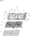
- Fig. 5 is an exploded perspective view of a fan unit and a cleaning unit of the indoor unit of the air-conditioning apparatus, seen from the upper right front side. It should be noted that in Fig. 3 , the left side of the figure is a front side of an indoor unit 100.
- the indoor unit 100 of the present embodiment includes a casing 1 in which an air inlet 4 is formed in an upper surface and an air outlet 5 is formed below the air inlet 4, a fan unit 30 having an axial fan 33 that is a propeller fan, and a heat exchanger 60 configured to exchange heat between the air (indoor air) taken into the casing 1 by the axial fan 33 and refrigerant.
- the air outlet 5 is formed in a lower surface of the casing 1.
- the casing 1 is in a substantially rectangular parallelepiped box shape, and is configured of a back plate 2 and a design panel 3.
- the back plate 2 constitutes a back surface of the casing 1.
- the design panel 3 constitutes a front surface (front part), right and left side surfaces, the upper surface, and the lower surface, of the casing 1. This means that the air inlet 4 and the air outlet 5 are formed in the design panel 3.
- a vertical wind direction plate 5a configured to adjust a vertical direction of the air blown out from the air outlet 5
- a lateral wind direction plate (not shown) configured to adjust a lateral direction of the air blown out from the air outlet 5.
- the fan unit 30 is provided downstream of the air inlet 4 in the casing 1.
- the fan unit 30 includes a fan outer frame 31 in which a bell mouth 32 is formed, at least one axial fan 33 provided in the bell mouth 32, and a motor 34 that drives the axial fan 33.
- two axial fans 33 are provided in parallel along the right and left direction of the casing 1.
- two bell mouths 32 are provided in parallel along the right and left direction of the casing 1.
- the number of axial fans 33 is just an example, and the number of axial fans 33 can be determined appropriately based on the air quantity that the indoor unit 100 is required.
- the motor 34 that drives the axial fan 33 is incorporated in a boss 33a of the axial fan 33 (see Fig. 14 described below).
- the fan unit 30, configured as described above, is to be mounted on the back plate 2 of the casing 1. The details of the amounting structure of the fan unit 30 to the back plate 2 will be described below.
- the heat exchanger 60 is provided downstream of the axial fan 33, that is, the fan unit 30, in the casing 1.
- the heat exchanger 60 includes a heat exchanger main body 61 configured to exchange heat between the air (indoor air) taken into the casing 1 and refrigerant.
- the heat exchanger main body 61 includes, from the front face side to the back face side of the casing 1, a first heat exchange element 62, a second heat exchange element 63, a third heat exchange element 64, and a fourth heat exchange element 65.
- Each of the first heat exchange element 62, the second heat exchange element 63, the third heat exchange element 64 and the fourth heat exchange element 65 is configured of a plurality of heat transfer fins 67 provided in parallel with predetermined intervals, and a plurality of heat transfer pipes 68 extending through the heat transfer fins 67 in a direction that the heat transfer fins 67 are provided in parallel.
- first heat exchange element 62, the second heat exchange element 63, the third heat exchange element 64 and the fourth heat exchange element 65 are formed in the same size and are arranged in a W shape when seen from a side face.
- configuration of the heat exchanger main body 61 is not limited to this configuration.
- the respective heat exchange elements may be in different sizes, and the number of heat exchange elements (that is, a shape when seen from a side face) may also be arbitrary.
- the heat exchanger 60 of the present embodiment includes a pair of side plates (right side plate 70 and left side plate 80) attached to the right and left ends of the heat exchanger main body 61.
- the heat exchanger 60 is mounted on the back plate 2 of the casing 1 via the right side plate 70 and the left side plate 80. The details of the mounting structure of the heat exchanger 60 on the back plate 2 will be described below.
- the indoor unit 100 of the present embodiment also includes, in the casing 1, a cleaning unit 90, a drain pan 97, and an electric component box 98.
- the cleaning unit 90 includes a cartridge 91, a filter 94, and a cleaning mechanism 95.
- the cartridge 91 is provided corresponding to the axial fan 33, and is disposed above the axial fan 33 (the air inlet 4, for example). Further, in the cartridge 91, an opening port 92 is formed at a position facing the axial fan 33.
- the cartridge 91 accommodates the filter 94 for removing dust from the air taken into the casing 1.
- two axial fans 33 are provided in the present embodiment.
- two cartridges 91 and two filters 94 are provided corresponding to the axial fans 33.
- the cleaning mechanism 95 configured to remove the dust adhering to the filter 94 and store them, is provided between the cartridges 91.
- the cartridge 91 moves the filter 94 in a right and left direction by a moving mechanism not shown, with a configuration of removing the dust adhering to the filter 94 during movement.
- the cleaning unit 90 is supported from the below by the fan unit 30.
- the drain pan 97 is arranged below the heat exchanger 60, and is configured to receive dew dripping from the heat exchanger 60 and collect it. It is configured such that the dew collected by the drain pan 97 is discharged to the outside of the casing 1 via a drain pipe not shown.
- the electric component box 98 is used for accommodating, for example, a control board for controlling the rotation speed and the like of the motor 34 that drives the axial fan 33.
- the electric component box 98 is disposed on the right side of the heat exchanger 60.
- the axial fan 33 In the case of adopting the axial fan 33 like the indoor unit 100 of the present embodiment, the axial fan 33 must be disposed above the heat exchanger 60. This means that as the heat exchanger 60 is enlarged, the axial fan 33 is disposed at a position separating forward from the back plate 2. The motor 34 that drives the axial fan 33 is also placed at a position separating forward from the back plate 2, along with the enlargement of the heat exchanger 60.
- the indoor unit 100 of the present embodiment has a configuration in which the cleaning unit 90 is supported by the fan unit 30. As such, in the indoor unit 100, much larger moment is applied to the screw holes of the mounting part (screw holes formed in the back plate 2), whereby breakage of the screw holes of the mounting part is more concerned.
- the back plate 2 may be made of resin with the aim of achieving weight reduction.
- the back plate 2 is made of resin, breakage of the screw holes of the mounting part is more concerned.
- Fig. 6 is an assembly perspective view of the back plate, the heat exchanger, and the fan unit, seen from the upper right front side, in the indoor unit of the air-conditioning apparatus according to the embodiment of the present invention.
- Fig. 7 is an exploded perspective view of the back plate, the heat exchanger, and the fan unit, seen from the upper right front side, in the indoor unit of the air-conditioning apparatus.
- Fig. 8 is an enlarged view of a part A of Fig. 7 .
- Fig. 9 is an enlarged view of a part B of Fig. 7 .
- Fig. 10 is a right side view of the back plate of the indoor unit of the air-conditioning apparatus.
- Fig. 11 is a left side view of the back plate of the indoor unit of the air-conditioning apparatus.
- Fig. 12 is a C-C sectional view of Fig. 7 .
- Fig. 13 is a D-D sectional view of Fig. 7 .
- Fig. 14 is an E-E sectional view of Fig. 2 .
- Fig. 15 is an enlarged view of a part F of Fig. 14 .
- Fig. 16 is an enlarged view of a part G of Fig. 14 .
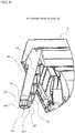
- the back plate 2 includes the pair of support arms 10 and 20 protruding forward.
- the support arm 10 provided in a protruding manner on the right side of the back plate 2 is formed in a substantially square pole shape.
- the inside of the support arm 10 is in a hollow shape to reduce the weight, and a rib 18 is formed inside to thereby secure the strength of the support arm 10.
- one side face (left side face facing the center side of the casing 1) of the support arm 10 is opened.
- one in which one side face is opened in this way is also referred to as a prism shape.
- the support arm 10 has a step 11 formed at a tip portion thereof.
- the tip portion of the support arm 10 includes a first tip portion 12, and a second tip portion 13 arranged backward by the step 11 from the first tip portion 12.
- the first tip portion 12 is provided with a boss 14 protruding forward, and a positioning pin 16. Further, the boss 14 has a screw hole 14a for fixing the fan unit 30. The positioning pin 16 is used for positioning the fan unit 30 before fixing the fan unit 30 with a screw.
- the screw hole 14a corresponds to a first screw hole of the present invention.
- the second tip portion 13 includes a boss 15 protruding forward, and a positioning pin 17. Further, the boss 15 has a screw hole 15a for fixing the heat exchanger 60. The positioning pin 17 is used for positioning the heat exchanger 60 before fixing the heat exchanger 60 with a screw.
- the support arm 20 provided in a protruding manner on the left side of the back plate 2 is also formed to be in an almost similar shape to that of the support arm 10.
- the support arm 20 is formed to be in a substantially square pole shape.
- the inside of the support arm 20 is in a hollow shape to reduce the weight, and a rib 28 is formed inside to thereby secure the strength of the support arm 20.
- the support arm 20 has a step 21 formed at a tip portion thereof.
- the tip portion of the support arm 20 includes a first tip portion 22, and a second tip portion 23 arranged backward by the step 21 from the first tip portion 22.
- the first tip portion 22 is provided with a boss 24 protruding forward, and a positioning pin 26. Further, the boss 24 has a screw hole 24a for fixing the fan unit 30. The positioning pin 26 is used for positioning the fan unit 30 before fixing the fan unit 30 with a screw.
- the screw hole 24a corresponds to the first screw hole of the present invention.
- the second tip portion 23 includes a boss 25 protruding forward. Further, the boss 25 has a screw hole 25a for fixing the heat exchanger 60. It should be noted that the boss 25 also functions as a positioning pin for positioning the heat exchanger 60 before fixing the heat exchanger 60 with a screw, as described below.
- the boss 25 corresponds to a positioning pin of the present invention.
- the shape of the support arms 10 and 20 is not limited to a substantially square pole shape.
- the support arms 10 and 20 may be formed in the shape of a substantially columnar shape or a substantially prism shaper other than a substantially square pole shape.
- it is preferable that the support arms 10 and 20 are in a substantially prism shape because they are able to support the fan unit 30 by surface contact.
- a guide groove 35 is formed along a front and back direction at a position facing the upper part of the support arm 10 formed on the right side of the back plate 2.
- a guide groove 45 is formed along a front and back direction at a position facing the upper part of the support arm 20 formed on the left side of the back plate 2.
- the guide groove 35 into which the support arm 10 is inserted slidably in a front and back direction, is formed between an outer guide wall 36 and an inner guide wall 37 protruded upward from the lower face of the fan outer frame 31. Further, the front face side of the guide groove 35 is closed at least partially by a mounting plate 38. This means that the guide groove 35 is in a form that the lower side and the back side are opened. Further, the mounting plate 38 is arranged to face the front of the support arm 10, that is, the tip portion (in more detail, the first tip portion 12) of the support arm 10. In the mounting plate 38, a through hole 39 is formed at a position facing the screw hole 14a formed in the boss 14 of the first tip portion 12. Further, in the mounting plate 38, a positioning hole 40 (through hole) is formed at a position facing the positioning pin 16 of the first tip portion 12 (see Fig. 6 ).
- the through hole 39 corresponds to a first through hole of the present invention
- the positioning hole 40 corresponds to a first recess of the present invention. It should be noted that the positioning hole 40 is not necessarily pierced.
- the guide groove 45 into which the support arm 20 is inserted slidably in a front and back direction, is formed between the outer guide wall 46 and the inner guide wall 47 protruded upward from the lower surface of the fan outer frame 31 (see Fig. 5 ). Further, the front face side of the guide groove 45 is closed at least partially by a mounting plate 48. This means that the guide groove 45 is in a form that the lower side and the back side are opened. Further, the mounting plate 48 is arranged to face the front of the support arm 20, that is, the tip portion (in more detail, the first tip portion 22) of the support arm 20. In the mounting plate 48, a through hole 49 is formed at a position facing the screw hole 24a formed in the boss 24 of the first tip portion 22. Further, in the mounting plate 48, a positioning hole 50 (through hole) is formed at a position facing the positioning pin 26 of the first tip portion 22 (see Fig. 6 ).
- the through hole 49 corresponds to the first through hole of the present invention
- the positioning hole 50 corresponds to the first recess of the present invention. It should be noted that the positioning hole 50 is not necessarily pierced.
- the heat exchanger 60 is mounted on the back plate constituting the back surface of the casing. As the heat exchanger 60 is enlarged, the center of gravity of the heat exchanger 60 comes to a position separating forward from the back plate 2. As such, when the heat exchanger 60 is mounted on the back plate 2 in a conventional configuration, larger moment is applied to the screw holes of the mounting part (screw holes formed in the back plate 2) along with the enlargement of the heat exchanger 60. As such, breakage of the screw holes of the mounting part is concerned.
- the back plate 2 may be made of resin with the aim of achieving weight reduction, for example.
- the back plate 2 is made of resin, breakage of the screw holes of the mounting part is more concerned.
- Fig. 17 is an assembly perspective view of the back plate, the heat exchanger, and the fan unit, seen from the lower right front side, in the indoor unit of the air-conditioning apparatus according to the embodiment of the present invention.
- Fig. 18 is an enlarged view of a part H of Fig. 17 .
- Fig. 19 is a drawing showing a state where the fan unit is drawn forward from the state shown in Fig. 18 .
- Fig. 20 is an assembly perspective view of the back plate, the heat exchanger, and the fan unit, seen from the lower left front side, in the indoor unit of the air-conditioning apparatus.
- Fig. 21 is an enlarged view of a part I of Fig. 20 .
- Fig. 22 is a drawing showing a state where the fan unit is drawn forward from the state shown in Fig. 21 .
- Fig. 23 is a perspective view of the right side plate of the heat exchanger, seen from the upper right front side, in the indoor unit of the air-conditioning apparatus.
- Fig. 24 is a perspective view of the left side plate of the heat exchanger, seen from the upper right back side, in the indoor unit of the air-conditioning apparatus.
- the right side plate 70 provided to the right end of the heat exchanger main body 61 includes a side plate main body 71 connected to the heat exchanger main body 61, and a mounting part 72 protruded upward from the side plate main body 71.
- the side plate main body 71 is connected to the right end of the heat exchanger main body 61 by welding, for example.
- the mounting part 72 is arranged to face the front of the support arm 10, that is, the tip portion (in more detail, the second tip portion 13) of the support arm 10.
- a through hole 73 is formed at a position facing the screw hole 15a formed in the boss 15 of the second tip portion 13.
- a positioning hole 74 (through hole) is formed at a position facing the positioning pin 17 of the second tip portion 13.
- the through hole 73 corresponds to a second through hole of the present invention
- the positioning hole 74 corresponds to a second recess of the present invention. It should be noted that the positioning hole 74 is not necessarily pieced.
- the left side plate 80 provided to the left end of the heat exchanger main body 61 includes a side plate main body 81 connected to the heat exchanger main body 61, and a mounting part 82 protruded upward from the side plate main body 81.
- a heat transfer pipe holding hole 81 a is formed at a position facing the U-shaped pipe.
- the side plate main body 81 is connected to the left end of the heat exchanger main body 61.
- the mounting part 82 is arranged to face the front of the support arm 20, that is, the tip portion (in more detail, the second tip portion 23) of the support arm 20.
- a through hole 83 is formed at a position facing the screw hole 25a formed in the boss 25 of the second tip portion 23.
- a flange 84 protruding backward is formed on the outer periphery of the through hole 83.
- a recess with the flange 84 being the outer peripheral wall, is formed behind the through hole 83. It is configured that in the recess, a tip portion of the boss 25, formed on the second tip portion 23 of the support arm 20, is inserted.
- the through hole 83 corresponds to the second through hole of the present invention
- the recess with the flange 84 being the outer peripheral wall corresponds to the second recess of the present invention.
- the heat exchanger 60 is fixed to the support arms 10 and 20.
- the screw fixing work of the heat exchanger 60 can be performed from the front side of the casing 1, whereby the mounting operability of the heat exchanger 60 can be improved.
- the heat exchanger 60 is mounted first.
- the positioning pin 17 provided to the second tip portion 13 of the support arm 10 is inserted to the positioning hole 74 formed in the mounting part 72 of the right side plate 70. Further, the boss 25 provided to the second tip portion 23 of the support arm 20 is inserted to the recess, in which the flange 84 forms the outer peripheral wall, formed in the mounting part 82 of the left side plate 80. Thereby, the heat exchanger 60 can be temporarily positioned with respect to the support arms 10 and 20, which makes the screw fixing work described below easy.
- the heat exchanger 60 is fixed to the support arms 10 and 20 with the screws.
- the screw 75 inserted in the through hole 73 of the mounting part 72 of the right side plate 70, is screwed and fixed to the screw hole 15a formed in the second tip portion 13 of the support arm 10 (see Figs. 18 , 19 , and elsewhere), and the screw inserted in the through hole 83 of the mounting part 82 of the left side plate 80, is screwed and fixed to the screw hole 25a formed in the second tip portion 23 of the support arm 20, whereby the heat exchanger 60 is fixed to the support arms 10 and 20.
- Fig. 25 is an explanatory diagram for explaining the moment acted on the screw hole of the mounting part of the heat exchanger in the indoor unit of the air-conditioning apparatus according to the embodiment of the present invention.
- Fig. 26 is an explanatory diagram for explaining the moment acted on the screw hole of the mounting part of the heat exchanger, when a conventional mounting structure is adopted as a mounting structure of the heat exchanger, in the indoor unit of the air-conditioning apparatus according to the embodiment of the present invention.
- a reference character G1 shown in Fig. 25 and Fig. 26 denotes the center of gravity of the heat exchanger 60.
- the support arms 10 and 20 as described in the present embodiment are not provided to the back plate.
- the heat exchanger 60 is mounted on the back plate 2 in the conventional mounting structure, the heat exchanger 60 is mounted at a position Z2 shown in Fig 26 .
- the mounting position Z2 and the center of gravity G1 of the heat exchanger 60 are distant from each other, whereby the moment M2 acted on the screw hole (screw hole for fixing the heat exchanger 60) formed at the mounting position Z2 on the back plate 2 is large. As such, breakage of the screw hole is concerned.
- the heat exchanger 60 is mounted on the second tip portions 13 and 23 of the support arms 10 and 20 as described above. As such, the heat exchanger 60 is mounted at a position Z1 shown in Fig. 25 . As such, as the distance between the mounting position Z1 and the center of gravity G1 of the heat exchanger 60 can be shortened, the moment M1 acted on the screw holes 15a and 25a (screw holes for fixing the heat exchanger 60) formed at the mounting position Z1 of the back plate 2 can be reduced. Therefore, it is possible to prevent breakage of the screw holes 15a and 25a.
- the heat exchanger 60 when the heat exchanger 60 is formed in a W shape when seen from a side face, it is preferable to have a structure in which the second tip portions 13 and 23 of the support arms 10 and 20 extend up to the position facing the upper end portion of the second heat exchange element 63 or the third heat exchange element 64 (a range of W shown in Fig. 25 ), as shown in Fig. 25 .
- the heat exchanger 60 is structured to have a W shape when seen from a side face, the center of gravity of the heat exchanger 60 locates near the above range of W. As such, the moment M1 acted on the screw holes 15a and 25a can be further reduced, whereby it is possible to further prevent breakage of the screw holes 15a and 25a.
- the first heat exchange element 62, the second heat exchange element 63, the third heat exchange element 64, and the fourth heat exchange element 65 are formed in the same size.
- the center of gravity of the heat exchanger 60 locates within the above range of W.
- the moment M1 acted on the screw holes 15a and 25a can be further reduced, whereby it is possible to further prevent breakage of the screw holes 15a and 25a.
- the fan unit 30 is mounted on the support arms 10 and 20 of the back plate 2.
- the fan unit 30 is placed on the upper part of the support arms 10 and 20.
- the guide grooves 35 and 45 are formed.
- the fan unit 30 is temporarily positioned with respect to the support arms 10 and 20. In this way, by temporarily positioning the fan unit 30, a screw fixing work of the fan unit 30 described below can be performed with ease.
- the fan unit 30 can be positioned temporarily if there is at least one of the guide groove 35 and the guide groove 45.
- the mounting plate 38 is in contact with the first tip portion 12 of the support arm 10
- the mounting plate 48 is in contact with the first tip portion 22 of the support arm 20.
- the step 11 is formed between the first tip portion 12 and the second tip portion 13 (the heat exchanger 60 mounting part).
- the step 21 is formed between the first tip portion 22 and the second tip portion 23 (heat exchanger 60 mounting part).
- the positioning pin 16 provided to the first tip portion 12 of the support arm 10 is inserted into the positioning hole 40 formed in the mounting plate 38.
- the positioning pin 26 provided to the first tip portion 22 of the support arm 20 is inserted into the positioning hole 50 formed in the mounting plate 48.
- a work of inserting the positioning pins 16 and 26 into the positioning holes 40 and 50 of the mounting plates 38 and 48 is performed in a state where the fan unit 30 is roughly positioned by the guide grooves 35 and 45 and the support arms 10 and 20.
- a work of inserting the positioning pins 16 and 26 into the positioning holes 40 and 50 of the mounting plates 38 and 48 can also be performed with ease.
- the fan unit 30 is fixed to the support arms 10 and 20 with screws.
- a screw inserted in the through hole 39 of the mounting plate 38 is screwed and fixed to the screw hole 14a formed in the first tip portion 12 of the support arm 10
- a screw inserted in the through hole 49 of the mounting plate 48 is screwed and fixed to the screw hole 24a formed in the first tip portion 22 of the support arm 20.
- the fan unit 30 is fixed to the support arms 10 and 20.
- Fig. 27 is an explanatory diagram for explaining the moment acted on the screw hole of the mounting part of the fan unit in the indoor unit of the air-conditioning apparatus according to the embodiment of the present invention.
- Fig. 28 is an explanatory diagram for explaining the moment acted on the screw hole of the mounting part of the fan unit, when a conventional mounting structure is adopted as a mounting structure of the fan unit, in the indoor unit of the air-conditioning apparatus according to the embodiment of the present invention.
- a reference character G2 shown in Fig. 27 and Fig. 28 denotes the center of gravity of the fan unit 30.
- the support arms 10 and 20 as described in the present embodiment are not provided to the back plate.
- the fan unit 30 when the fan unit 30 is mounted on the back plate 2 in the conventional mounting structure, the fan unit 30 is mounted at a position Z4 shown in Fig 28 .
- the mounting position Z4 and the center of gravity G2 of the fan unit 30 are distant from each other, whereby the moment M4 acted on the screw hole (screw hole for fixing the fan unit 30) formed at the mounting position Z4 on the back plate 2 is large. As such, breakage of the screw hole is concerned.
- the indoor unit 100 of the present embodiment is structured such that a partial load of the fan unit 30 is supported by the support arms 10 and 20. As such, as the moment acted on the screw hole for fixing the fan unit 30 can be reduced, it is possible to prevent breakage of the screw hole. Further, in the indoor unit 100 of the present embodiment, the fan unit 30 is mounted on the first tip portions 12 and 22 of the support arms 10 and 20. As such, the fan unit 30 is mounted at a position Z3 shown in Fig. 27 .
- the moment M3 acted on the screw holes 14a and 24a (screw holes for fixing the fan unit 30) formed at the mounting position Z3 on the back plate 2 can be reduced. Thereby, it is possible to further prevent breakage of the screw holes 14a and 24a.
- the first tip portions 12 and 22 of the support arms 10 and 20 extend forward beyond the center of gravity G2 of the fan unit 30.
- the entire load of the fan unit 30 can be supported by the support arms 10 and 20.
- no moment is acted on the screw holes for fixing the fan unit 30, whereby it is possible to securely prevent breakage of the screw holes.
- this effect can also be achieved in the case other than the case where the screw holes 14a and 24a for fixing the fan unit 30 are formed in the first tip portions 12 and 22 of the support arms 10 and 20, that is, the case where the screw holes for fixing the fan unit 30 are formed at positions other than the screw holes 14a and 24a.
Landscapes
- Engineering & Computer Science (AREA)
- Chemical & Material Sciences (AREA)
- Combustion & Propulsion (AREA)
- Mechanical Engineering (AREA)
- General Engineering & Computer Science (AREA)
- Chemical Kinetics & Catalysis (AREA)
- Air Filters, Heat-Exchange Apparatuses, And Housings Of Air-Conditioning Units (AREA)
- Air-Conditioning Room Units, And Self-Contained Units In General (AREA)
Applications Claiming Priority (1)
| Application Number | Priority Date | Filing Date | Title |
|---|---|---|---|
| PCT/JP2015/061872 WO2016166894A1 (fr) | 2015-04-17 | 2015-04-17 | Unité intérieure pour climatiseur |
Publications (3)
| Publication Number | Publication Date |
|---|---|
| EP3104087A1 true EP3104087A1 (fr) | 2016-12-14 |
| EP3104087A4 EP3104087A4 (fr) | 2017-05-03 |
| EP3104087B1 EP3104087B1 (fr) | 2021-01-20 |
Family
ID=57125862
Family Applications (1)
| Application Number | Title | Priority Date | Filing Date |
|---|---|---|---|
| EP15868661.8A Active EP3104087B1 (fr) | 2015-04-17 | 2015-04-17 | Unité intérieure pour climatiseur |
Country Status (7)
| Country | Link |
|---|---|
| US (1) | US10746416B2 (fr) |
| EP (1) | EP3104087B1 (fr) |
| JP (1) | JP6456483B2 (fr) |
| CN (1) | CN106716021B (fr) |
| AU (1) | AU2015391312B2 (fr) |
| RU (1) | RU2669041C1 (fr) |
| WO (1) | WO2016166894A1 (fr) |
Cited By (2)
| Publication number | Priority date | Publication date | Assignee | Title |
|---|---|---|---|---|
| WO2018192386A1 (fr) * | 2017-04-18 | 2018-10-25 | 青岛海尔空调器有限总公司 | Unité intérieure de climatiseur |
| WO2020060322A1 (fr) | 2018-09-21 | 2020-03-26 | Samsung Electronics Co., Ltd. | Climatiseur |
Families Citing this family (2)
| Publication number | Priority date | Publication date | Assignee | Title |
|---|---|---|---|---|
| CN111433520B (zh) * | 2017-12-13 | 2021-07-06 | 三菱电机株式会社 | 热交换单元以及搭载热交换单元的空调装置 |
| EP3715733B1 (fr) * | 2019-01-31 | 2023-08-30 | GD Midea Air-Conditioning Equipment Co., Ltd. | Section intérieure de climatiseur et climatiseur |
Citations (3)
| Publication number | Priority date | Publication date | Assignee | Title |
|---|---|---|---|---|
| GB2305500A (en) * | 1995-09-25 | 1997-04-09 | Mitsubishi Electric Corp | Fan units |
| EP1767873A2 (fr) * | 2005-09-22 | 2007-03-28 | LG Electronics, Inc. | Dispositif de conditionnement d'air |
| WO2014190780A1 (fr) * | 2013-05-31 | 2014-12-04 | 美的集团股份有限公司 | Appareil d'admission d'air utilisé pour un conditionneur d'air et unité intérieure de conditionneur d'air qui comprend ce dernier |
Family Cites Families (24)
| Publication number | Priority date | Publication date | Assignee | Title |
|---|---|---|---|---|
| JPH0727361A (ja) | 1993-07-13 | 1995-01-27 | Mitsubishi Heavy Ind Ltd | 空気調和機 |
| JP3045159B2 (ja) | 1998-02-27 | 2000-05-29 | ダイキン工業株式会社 | 空気調和装置の室内機及び該室内機の据付構造 |
| JP3120798B2 (ja) * | 1998-12-01 | 2000-12-25 | ダイキン工業株式会社 | 空気調和装置の室内機 |
| JP2000241016A (ja) * | 1999-02-19 | 2000-09-08 | Fujitsu General Ltd | 空気調和機の据付装置. |
| WO2000057113A1 (fr) | 1999-03-24 | 2000-09-28 | Francisco Menezes | Ensemble chauffe-eau electrique |
| JP2002106954A (ja) * | 2000-09-29 | 2002-04-10 | Fujitsu General Ltd | 空気調和機 |
| JP4110375B2 (ja) * | 2002-06-27 | 2008-07-02 | 株式会社富士通ゼネラル | 空気調和機 |
| KR100633170B1 (ko) * | 2004-05-12 | 2006-10-12 | 엘지전자 주식회사 | 박형 공기조화기 |
| WO2006078083A2 (fr) * | 2005-01-24 | 2006-07-27 | Lg Electronics Inc. | Conditionneur d'air |
| BRPI0518503A2 (pt) * | 2005-01-26 | 2008-12-02 | Lg Electronics Inc | aparelho de ar condicionado |
| AU2006213929B2 (en) * | 2005-09-13 | 2011-04-14 | Fujitsu General Limited | Air conditioner and method for assembling the same |
| JP5422953B2 (ja) * | 2007-11-12 | 2014-02-19 | ダイキン工業株式会社 | 空気調和機用室内機 |
| CN102308153B (zh) | 2009-02-05 | 2015-03-04 | 三菱电机株式会社 | 空气调节器的室内机及空气调节器 |
| JP5720918B2 (ja) * | 2009-12-11 | 2015-05-20 | 株式会社富士通ゼネラル | ダクト型空気調和機 |
| JP5565664B2 (ja) * | 2009-12-11 | 2014-08-06 | 株式会社富士通ゼネラル | ダクト型空気調和機 |
| JP5474200B2 (ja) * | 2010-08-04 | 2014-04-16 | 三菱電機株式会社 | 空気調和機の室内機、及び空気調和機 |
| JP5409544B2 (ja) * | 2010-08-04 | 2014-02-05 | 三菱電機株式会社 | 空気調和機の室内機、及び空気調和機 |
| CN103140717B (zh) | 2010-08-04 | 2016-05-04 | 三菱电机株式会社 | 空气调节机的室内机及空气调节机 |
| JP5365675B2 (ja) * | 2011-09-30 | 2013-12-11 | ダイキン工業株式会社 | 空調室内機 |
| JP5595371B2 (ja) * | 2011-12-26 | 2014-09-24 | 三菱電機株式会社 | 空気調和機 |
| JP5871665B2 (ja) * | 2012-03-05 | 2016-03-01 | 三菱電機株式会社 | 空気調和機の室内機 |
| JP5999944B2 (ja) * | 2012-03-22 | 2016-09-28 | ダイキン工業株式会社 | 空調室内機 |
| EP3406987B1 (fr) * | 2016-01-21 | 2021-05-19 | Mitsubishi Electric Corporation | Unité intérieure de climatiseurs |
| US10378780B2 (en) * | 2017-01-24 | 2019-08-13 | The Air Center LLC | Apparatus and method for cleaning split system air conditioners |
-
2015
- 2015-04-17 RU RU2017134679A patent/RU2669041C1/ru active
- 2015-04-17 JP JP2017512176A patent/JP6456483B2/ja active Active
- 2015-04-17 EP EP15868661.8A patent/EP3104087B1/fr active Active
- 2015-04-17 US US15/545,353 patent/US10746416B2/en active Active
- 2015-04-17 AU AU2015391312A patent/AU2015391312B2/en active Active
- 2015-04-17 WO PCT/JP2015/061872 patent/WO2016166894A1/fr active Application Filing
- 2015-04-17 CN CN201580048364.XA patent/CN106716021B/zh active Active
Patent Citations (4)
| Publication number | Priority date | Publication date | Assignee | Title |
|---|---|---|---|---|
| GB2305500A (en) * | 1995-09-25 | 1997-04-09 | Mitsubishi Electric Corp | Fan units |
| EP1767873A2 (fr) * | 2005-09-22 | 2007-03-28 | LG Electronics, Inc. | Dispositif de conditionnement d'air |
| WO2014190780A1 (fr) * | 2013-05-31 | 2014-12-04 | 美的集团股份有限公司 | Appareil d'admission d'air utilisé pour un conditionneur d'air et unité intérieure de conditionneur d'air qui comprend ce dernier |
| EP3006837A1 (fr) * | 2013-05-31 | 2016-04-13 | Midea Group Co., Ltd. | Appareil d'admission d'air utilisé pour un conditionneur d'air et unité intérieure de conditionneur d'air qui comprend ce dernier |
Non-Patent Citations (1)
| Title |
|---|
| See also references of WO2016166894A1 * |
Cited By (5)
| Publication number | Priority date | Publication date | Assignee | Title |
|---|---|---|---|---|
| WO2018192386A1 (fr) * | 2017-04-18 | 2018-10-25 | 青岛海尔空调器有限总公司 | Unité intérieure de climatiseur |
| WO2020060322A1 (fr) | 2018-09-21 | 2020-03-26 | Samsung Electronics Co., Ltd. | Climatiseur |
| US20200096207A1 (en) * | 2018-09-21 | 2020-03-26 | Samsung Electronics Co., Ltd. | Air conditioner |
| EP3818307A4 (fr) * | 2018-09-21 | 2021-08-18 | Samsung Electronics Co., Ltd. | Climatiseur |
| US11668473B2 (en) | 2018-09-21 | 2023-06-06 | Samsung Electronics Co., Ltd. | Air conditioner |
Also Published As
| Publication number | Publication date |
|---|---|
| AU2015391312A1 (en) | 2017-08-24 |
| US10746416B2 (en) | 2020-08-18 |
| CN106716021B (zh) | 2019-07-09 |
| JPWO2016166894A1 (ja) | 2017-11-09 |
| EP3104087A4 (fr) | 2017-05-03 |
| EP3104087B1 (fr) | 2021-01-20 |
| JP6456483B2 (ja) | 2019-01-23 |
| RU2669041C1 (ru) | 2018-10-05 |
| WO2016166894A1 (fr) | 2016-10-20 |
| US20180010812A1 (en) | 2018-01-11 |
| AU2015391312B2 (en) | 2018-11-08 |
| CN106716021A (zh) | 2017-05-24 |
Similar Documents
| Publication | Publication Date | Title |
|---|---|---|
| EP3104087B1 (fr) | Unité intérieure pour climatiseur | |
| EP2469194B1 (fr) | Conditionneur d'air mural | |
| EP2921795B1 (fr) | Unité extérieure pour climatiseur | |
| WO2013129527A1 (fr) | Climatiseur incorporé | |
| WO2017208348A1 (fr) | Unité intérieure de climatiseur | |
| JP2009030829A (ja) | 空気調和装置 | |
| JP6299552B2 (ja) | 天井埋込型空気調和機 | |
| EP2947397B1 (fr) | Dispositif de réglage de direction de vent d'appareil de climatisation et appareil de climatisation | |
| JP6289663B2 (ja) | 空気調和装置の室内機 | |
| EP3076095B1 (fr) | Unité intérieure | |
| JP5260691B2 (ja) | 空気調和機 | |
| JP2017166751A (ja) | 天井埋込型空気調和機 | |
| JP2015017785A (ja) | 空気調和機 | |
| JP2012207801A (ja) | 壁埋込型空調室内ユニット | |
| CN107796105B (zh) | 一种空调设备及其装配方法 | |
| CN102854946A (zh) | 风扇组合 | |
| JP6847306B2 (ja) | 空気調和機の室外機 | |
| JP2016121864A (ja) | 空気調和機の室外機 | |
| EP2980502B1 (fr) | Climatiseur | |
| JP6110598B2 (ja) | 熱交換換気装置 | |
| JP5855998B2 (ja) | 空気調和機 | |
| CN205316477U (zh) | 空调室内挂机 | |
| JP2007322045A (ja) | 空気調和機の室外機 | |
| CN106288270A (zh) | 格栅固定结构和空调室内机 |
Legal Events
| Date | Code | Title | Description |
|---|---|---|---|
| STAA | Information on the status of an ep patent application or granted ep patent |
Free format text: STATUS: THE INTERNATIONAL PUBLICATION HAS BEEN MADE |
|
| PUAI | Public reference made under article 153(3) epc to a published international application that has entered the european phase |
Free format text: ORIGINAL CODE: 0009012 |
|
| STAA | Information on the status of an ep patent application or granted ep patent |
Free format text: STATUS: REQUEST FOR EXAMINATION WAS MADE |
|
| 17P | Request for examination filed |
Effective date: 20160617 |
|
| AK | Designated contracting states |
Kind code of ref document: A1 Designated state(s): AL AT BE BG CH CY CZ DE DK EE ES FI FR GB GR HR HU IE IS IT LI LT LU LV MC MK MT NL NO PL PT RO RS SE SI SK SM TR |
|
| AX | Request for extension of the european patent |
Extension state: BA ME |
|
| A4 | Supplementary search report drawn up and despatched |
Effective date: 20170403 |
|
| RIC1 | Information provided on ipc code assigned before grant |
Ipc: F24F 1/00 20110101AFI20170328BHEP Ipc: F24F 13/32 20060101ALI20170328BHEP |
|
| DAV | Request for validation of the european patent (deleted) | ||
| DAX | Request for extension of the european patent (deleted) | ||
| STAA | Information on the status of an ep patent application or granted ep patent |
Free format text: STATUS: EXAMINATION IS IN PROGRESS |
|
| 17Q | First examination report despatched |
Effective date: 20190809 |
|
| REG | Reference to a national code |
Ref country code: DE Ref legal event code: R079 Ref document number: 602015065081 Country of ref document: DE Free format text: PREVIOUS MAIN CLASS: F24F0001000000 Ipc: F24F0013320000 |
|
| RIC1 | Information provided on ipc code assigned before grant |
Ipc: F24F 1/0029 20190101ALI20200609BHEP Ipc: F24F 13/32 20060101AFI20200609BHEP Ipc: F24F 1/0057 20190101ALI20200609BHEP |
|
| GRAP | Despatch of communication of intention to grant a patent |
Free format text: ORIGINAL CODE: EPIDOSNIGR1 |
|
| STAA | Information on the status of an ep patent application or granted ep patent |
Free format text: STATUS: GRANT OF PATENT IS INTENDED |
|
| GRAJ | Information related to disapproval of communication of intention to grant by the applicant or resumption of examination proceedings by the epo deleted |
Free format text: ORIGINAL CODE: EPIDOSDIGR1 |
|
| GRAP | Despatch of communication of intention to grant a patent |
Free format text: ORIGINAL CODE: EPIDOSNIGR1 |
|
| INTG | Intention to grant announced |
Effective date: 20200717 |
|
| INTG | Intention to grant announced |
Effective date: 20200720 |
|
| INTG | Intention to grant announced |
Effective date: 20200729 |
|
| INTG | Intention to grant announced |
Effective date: 20200807 |
|
| GRAS | Grant fee paid |
Free format text: ORIGINAL CODE: EPIDOSNIGR3 |
|
| GRAA | (expected) grant |
Free format text: ORIGINAL CODE: 0009210 |
|
| STAA | Information on the status of an ep patent application or granted ep patent |
Free format text: STATUS: THE PATENT HAS BEEN GRANTED |
|
| AK | Designated contracting states |
Kind code of ref document: B1 Designated state(s): AL AT BE BG CH CY CZ DE DK EE ES FI FR GB GR HR HU IE IS IT LI LT LU LV MC MK MT NL NO PL PT RO RS SE SI SK SM TR |
|
| REG | Reference to a national code |
Ref country code: GB Ref legal event code: FG4D |
|
| REG | Reference to a national code |
Ref country code: CH Ref legal event code: EP |
|
| REG | Reference to a national code |
Ref country code: DE Ref legal event code: R096 Ref document number: 602015065081 Country of ref document: DE |
|
| REG | Reference to a national code |
Ref country code: AT Ref legal event code: REF Ref document number: 1356750 Country of ref document: AT Kind code of ref document: T Effective date: 20210215 |
|
| REG | Reference to a national code |
Ref country code: IE Ref legal event code: FG4D |
|
| REG | Reference to a national code |
Ref country code: NL Ref legal event code: MP Effective date: 20210120 |
|
| REG | Reference to a national code |
Ref country code: LT Ref legal event code: MG9D |
|
| REG | Reference to a national code |
Ref country code: AT Ref legal event code: MK05 Ref document number: 1356750 Country of ref document: AT Kind code of ref document: T Effective date: 20210120 |
|
| PG25 | Lapsed in a contracting state [announced via postgrant information from national office to epo] |
Ref country code: NO Free format text: LAPSE BECAUSE OF FAILURE TO SUBMIT A TRANSLATION OF THE DESCRIPTION OR TO PAY THE FEE WITHIN THE PRESCRIBED TIME-LIMIT Effective date: 20210420 Ref country code: PT Free format text: LAPSE BECAUSE OF FAILURE TO SUBMIT A TRANSLATION OF THE DESCRIPTION OR TO PAY THE FEE WITHIN THE PRESCRIBED TIME-LIMIT Effective date: 20210520 Ref country code: BG Free format text: LAPSE BECAUSE OF FAILURE TO SUBMIT A TRANSLATION OF THE DESCRIPTION OR TO PAY THE FEE WITHIN THE PRESCRIBED TIME-LIMIT Effective date: 20210420 Ref country code: NL Free format text: LAPSE BECAUSE OF FAILURE TO SUBMIT A TRANSLATION OF THE DESCRIPTION OR TO PAY THE FEE WITHIN THE PRESCRIBED TIME-LIMIT Effective date: 20210120 Ref country code: HR Free format text: LAPSE BECAUSE OF FAILURE TO SUBMIT A TRANSLATION OF THE DESCRIPTION OR TO PAY THE FEE WITHIN THE PRESCRIBED TIME-LIMIT Effective date: 20210120 Ref country code: FI Free format text: LAPSE BECAUSE OF FAILURE TO SUBMIT A TRANSLATION OF THE DESCRIPTION OR TO PAY THE FEE WITHIN THE PRESCRIBED TIME-LIMIT Effective date: 20210120 Ref country code: GR Free format text: LAPSE BECAUSE OF FAILURE TO SUBMIT A TRANSLATION OF THE DESCRIPTION OR TO PAY THE FEE WITHIN THE PRESCRIBED TIME-LIMIT Effective date: 20210421 Ref country code: LT Free format text: LAPSE BECAUSE OF FAILURE TO SUBMIT A TRANSLATION OF THE DESCRIPTION OR TO PAY THE FEE WITHIN THE PRESCRIBED TIME-LIMIT Effective date: 20210120 |
|
| PG25 | Lapsed in a contracting state [announced via postgrant information from national office to epo] |
Ref country code: AT Free format text: LAPSE BECAUSE OF FAILURE TO SUBMIT A TRANSLATION OF THE DESCRIPTION OR TO PAY THE FEE WITHIN THE PRESCRIBED TIME-LIMIT Effective date: 20210120 Ref country code: LV Free format text: LAPSE BECAUSE OF FAILURE TO SUBMIT A TRANSLATION OF THE DESCRIPTION OR TO PAY THE FEE WITHIN THE PRESCRIBED TIME-LIMIT Effective date: 20210120 Ref country code: RS Free format text: LAPSE BECAUSE OF FAILURE TO SUBMIT A TRANSLATION OF THE DESCRIPTION OR TO PAY THE FEE WITHIN THE PRESCRIBED TIME-LIMIT Effective date: 20210120 Ref country code: PL Free format text: LAPSE BECAUSE OF FAILURE TO SUBMIT A TRANSLATION OF THE DESCRIPTION OR TO PAY THE FEE WITHIN THE PRESCRIBED TIME-LIMIT Effective date: 20210120 Ref country code: SE Free format text: LAPSE BECAUSE OF FAILURE TO SUBMIT A TRANSLATION OF THE DESCRIPTION OR TO PAY THE FEE WITHIN THE PRESCRIBED TIME-LIMIT Effective date: 20210120 |
|
| PG25 | Lapsed in a contracting state [announced via postgrant information from national office to epo] |
Ref country code: IS Free format text: LAPSE BECAUSE OF FAILURE TO SUBMIT A TRANSLATION OF THE DESCRIPTION OR TO PAY THE FEE WITHIN THE PRESCRIBED TIME-LIMIT Effective date: 20210520 |
|
| REG | Reference to a national code |
Ref country code: DE Ref legal event code: R097 Ref document number: 602015065081 Country of ref document: DE |
|
| PG25 | Lapsed in a contracting state [announced via postgrant information from national office to epo] |
Ref country code: CZ Free format text: LAPSE BECAUSE OF FAILURE TO SUBMIT A TRANSLATION OF THE DESCRIPTION OR TO PAY THE FEE WITHIN THE PRESCRIBED TIME-LIMIT Effective date: 20210120 Ref country code: EE Free format text: LAPSE BECAUSE OF FAILURE TO SUBMIT A TRANSLATION OF THE DESCRIPTION OR TO PAY THE FEE WITHIN THE PRESCRIBED TIME-LIMIT Effective date: 20210120 Ref country code: SM Free format text: LAPSE BECAUSE OF FAILURE TO SUBMIT A TRANSLATION OF THE DESCRIPTION OR TO PAY THE FEE WITHIN THE PRESCRIBED TIME-LIMIT Effective date: 20210120 |
|
| PLBE | No opposition filed within time limit |
Free format text: ORIGINAL CODE: 0009261 |
|
| STAA | Information on the status of an ep patent application or granted ep patent |
Free format text: STATUS: NO OPPOSITION FILED WITHIN TIME LIMIT |
|
| PG25 | Lapsed in a contracting state [announced via postgrant information from national office to epo] |
Ref country code: SK Free format text: LAPSE BECAUSE OF FAILURE TO SUBMIT A TRANSLATION OF THE DESCRIPTION OR TO PAY THE FEE WITHIN THE PRESCRIBED TIME-LIMIT Effective date: 20210120 Ref country code: RO Free format text: LAPSE BECAUSE OF FAILURE TO SUBMIT A TRANSLATION OF THE DESCRIPTION OR TO PAY THE FEE WITHIN THE PRESCRIBED TIME-LIMIT Effective date: 20210120 Ref country code: MC Free format text: LAPSE BECAUSE OF FAILURE TO SUBMIT A TRANSLATION OF THE DESCRIPTION OR TO PAY THE FEE WITHIN THE PRESCRIBED TIME-LIMIT Effective date: 20210120 Ref country code: ES Free format text: LAPSE BECAUSE OF FAILURE TO SUBMIT A TRANSLATION OF THE DESCRIPTION OR TO PAY THE FEE WITHIN THE PRESCRIBED TIME-LIMIT Effective date: 20210120 Ref country code: DK Free format text: LAPSE BECAUSE OF FAILURE TO SUBMIT A TRANSLATION OF THE DESCRIPTION OR TO PAY THE FEE WITHIN THE PRESCRIBED TIME-LIMIT Effective date: 20210120 |
|
| 26N | No opposition filed |
Effective date: 20211021 |
|
| GBPC | Gb: european patent ceased through non-payment of renewal fee |
Effective date: 20210420 |
|
| PG25 | Lapsed in a contracting state [announced via postgrant information from national office to epo] |
Ref country code: LU Free format text: LAPSE BECAUSE OF NON-PAYMENT OF DUE FEES Effective date: 20210417 |
|
| REG | Reference to a national code |
Ref country code: BE Ref legal event code: MM Effective date: 20210430 |
|
| PG25 | Lapsed in a contracting state [announced via postgrant information from national office to epo] |
Ref country code: AL Free format text: LAPSE BECAUSE OF FAILURE TO SUBMIT A TRANSLATION OF THE DESCRIPTION OR TO PAY THE FEE WITHIN THE PRESCRIBED TIME-LIMIT Effective date: 20210120 Ref country code: CH Free format text: LAPSE BECAUSE OF NON-PAYMENT OF DUE FEES Effective date: 20210430 Ref country code: LI Free format text: LAPSE BECAUSE OF NON-PAYMENT OF DUE FEES Effective date: 20210430 Ref country code: GB Free format text: LAPSE BECAUSE OF NON-PAYMENT OF DUE FEES Effective date: 20210420 Ref country code: FR Free format text: LAPSE BECAUSE OF NON-PAYMENT OF DUE FEES Effective date: 20210430 |
|
| PG25 | Lapsed in a contracting state [announced via postgrant information from national office to epo] |
Ref country code: SI Free format text: LAPSE BECAUSE OF FAILURE TO SUBMIT A TRANSLATION OF THE DESCRIPTION OR TO PAY THE FEE WITHIN THE PRESCRIBED TIME-LIMIT Effective date: 20210120 |
|
| PG25 | Lapsed in a contracting state [announced via postgrant information from national office to epo] |
Ref country code: IT Free format text: LAPSE BECAUSE OF FAILURE TO SUBMIT A TRANSLATION OF THE DESCRIPTION OR TO PAY THE FEE WITHIN THE PRESCRIBED TIME-LIMIT Effective date: 20210120 Ref country code: IE Free format text: LAPSE BECAUSE OF NON-PAYMENT OF DUE FEES Effective date: 20210417 |
|
| PG25 | Lapsed in a contracting state [announced via postgrant information from national office to epo] |
Ref country code: IS Free format text: LAPSE BECAUSE OF FAILURE TO SUBMIT A TRANSLATION OF THE DESCRIPTION OR TO PAY THE FEE WITHIN THE PRESCRIBED TIME-LIMIT Effective date: 20210520 |
|
| PG25 | Lapsed in a contracting state [announced via postgrant information from national office to epo] |
Ref country code: BE Free format text: LAPSE BECAUSE OF NON-PAYMENT OF DUE FEES Effective date: 20210430 |
|
| PG25 | Lapsed in a contracting state [announced via postgrant information from national office to epo] |
Ref country code: HU Free format text: LAPSE BECAUSE OF FAILURE TO SUBMIT A TRANSLATION OF THE DESCRIPTION OR TO PAY THE FEE WITHIN THE PRESCRIBED TIME-LIMIT; INVALID AB INITIO Effective date: 20150417 |
|
| P01 | Opt-out of the competence of the unified patent court (upc) registered |
Effective date: 20230512 |
|
| PG25 | Lapsed in a contracting state [announced via postgrant information from national office to epo] |
Ref country code: CY Free format text: LAPSE BECAUSE OF FAILURE TO SUBMIT A TRANSLATION OF THE DESCRIPTION OR TO PAY THE FEE WITHIN THE PRESCRIBED TIME-LIMIT Effective date: 20210120 |
|
| PGFP | Annual fee paid to national office [announced via postgrant information from national office to epo] |
Ref country code: DE Payment date: 20230228 Year of fee payment: 9 |
|
| PG25 | Lapsed in a contracting state [announced via postgrant information from national office to epo] |
Ref country code: MK Free format text: LAPSE BECAUSE OF FAILURE TO SUBMIT A TRANSLATION OF THE DESCRIPTION OR TO PAY THE FEE WITHIN THE PRESCRIBED TIME-LIMIT Effective date: 20210120 |