EP3103584A1 - Élément d'étanchéité pour machines-outils - Google Patents
Élément d'étanchéité pour machines-outils Download PDFInfo
- Publication number
- EP3103584A1 EP3103584A1 EP15746826.5A EP15746826A EP3103584A1 EP 3103584 A1 EP3103584 A1 EP 3103584A1 EP 15746826 A EP15746826 A EP 15746826A EP 3103584 A1 EP3103584 A1 EP 3103584A1
- Authority
- EP
- European Patent Office
- Prior art keywords
- elastic member
- machine tools
- sealing member
- supporting member
- face
- Prior art date
- Legal status (The legal status is an assumption and is not a legal conclusion. Google has not performed a legal analysis and makes no representation as to the accuracy of the status listed.)
- Granted
Links
Images


Classifications
-
- B—PERFORMING OPERATIONS; TRANSPORTING
- B23—MACHINE TOOLS; METAL-WORKING NOT OTHERWISE PROVIDED FOR
- B23Q—DETAILS, COMPONENTS, OR ACCESSORIES FOR MACHINE TOOLS, e.g. ARRANGEMENTS FOR COPYING OR CONTROLLING; MACHINE TOOLS IN GENERAL CHARACTERISED BY THE CONSTRUCTION OF PARTICULAR DETAILS OR COMPONENTS; COMBINATIONS OR ASSOCIATIONS OF METAL-WORKING MACHINES, NOT DIRECTED TO A PARTICULAR RESULT
- B23Q11/00—Accessories fitted to machine tools for keeping tools or parts of the machine in good working condition or for cooling work; Safety devices specially combined with or arranged in, or specially adapted for use in connection with, machine tools
- B23Q11/08—Protective coverings for parts of machine tools; Splash guards
- B23Q11/0825—Relatively slidable coverings, e.g. telescopic
-
- B—PERFORMING OPERATIONS; TRANSPORTING
- B23—MACHINE TOOLS; METAL-WORKING NOT OTHERWISE PROVIDED FOR
- B23Q—DETAILS, COMPONENTS, OR ACCESSORIES FOR MACHINE TOOLS, e.g. ARRANGEMENTS FOR COPYING OR CONTROLLING; MACHINE TOOLS IN GENERAL CHARACTERISED BY THE CONSTRUCTION OF PARTICULAR DETAILS OR COMPONENTS; COMBINATIONS OR ASSOCIATIONS OF METAL-WORKING MACHINES, NOT DIRECTED TO A PARTICULAR RESULT
- B23Q11/00—Accessories fitted to machine tools for keeping tools or parts of the machine in good working condition or for cooling work; Safety devices specially combined with or arranged in, or specially adapted for use in connection with, machine tools
- B23Q11/08—Protective coverings for parts of machine tools; Splash guards
- B23Q11/0875—Wipers for clearing foreign matter from slideways or slidable coverings
-
- B—PERFORMING OPERATIONS; TRANSPORTING
- B26—HAND CUTTING TOOLS; CUTTING; SEVERING
- B26D—CUTTING; DETAILS COMMON TO MACHINES FOR PERFORATING, PUNCHING, CUTTING-OUT, STAMPING-OUT OR SEVERING
- B26D7/00—Details of apparatus for cutting, cutting-out, stamping-out, punching, perforating, or severing by means other than cutting
- B26D7/08—Means for treating work or cutting member to facilitate cutting
- B26D7/086—Means for treating work or cutting member to facilitate cutting by vibrating, e.g. ultrasonically
-
- F—MECHANICAL ENGINEERING; LIGHTING; HEATING; WEAPONS; BLASTING
- F16—ENGINEERING ELEMENTS AND UNITS; GENERAL MEASURES FOR PRODUCING AND MAINTAINING EFFECTIVE FUNCTIONING OF MACHINES OR INSTALLATIONS; THERMAL INSULATION IN GENERAL
- F16J—PISTONS; CYLINDERS; SEALINGS
- F16J15/00—Sealings
- F16J15/16—Sealings between relatively-moving surfaces
- F16J15/32—Sealings between relatively-moving surfaces with elastic sealings, e.g. O-rings
- F16J15/3204—Sealings between relatively-moving surfaces with elastic sealings, e.g. O-rings with at least one lip
Definitions
- the present invention relates to a sealing member for machine tools.
- Machine tools such as a lathe and a miller are the most basic machinery generally used in the manufacturing industry.
- various sealing members for example, a slide seal, a telescopic seal, a covering seal, and a lip seal are used in order to protect a driving mechanism and the like from swarf, a coolant (cutting oil) or the like.
- the telescopic seal is a wiper member for use in a telescopic cover.
- the telescopic cover has a tube-shaped structure like a telescope in which a plurality of box-shaped covers of different sizes are arranged in different levels with a gap provided therebetween, the covers being configured to be coupled with each other via a coupling member such as a pantograph, and be stretchable as a whole along with, for example, shift of a tool of a machine tool.
- the telescopic seal is a wiper member for filling a clearance between covers, and is attached to an end portion of an outer cover so as to be in sliding contact with an outer surface of an inner cover, thereby preventing swarf or the like from entering the inside of the corner (inside of the telescopic cover).
- the wiper 1 for machine tools has a wiper main body 2 formed from rubber and a supporting member 4 bonded to the wiper main body 2, and is configured to be attachable to a lower face of a distal end portion of a covering member 5 via a fixture or the like.
- the wiper 1 for machine tools prevents swarf or the like present on an outer face of the covering member 5 from entering the inside of the cover through a clearance by making a lip portion 3 formed at a distal end portion of the wiper main body 2 be in sliding contact with the outer face of the covering member 5 at the inner side (see, for example, [Related Art] of Patent Literature 1).
- Patent Literature 1 Japanese Unexamined Patent Publication No. 2000-308944
- this wiper for machine tools When attached to a covering member, such a wiper for machine tools as shown in FIG. 10 has a large part of a wiper main body exposed outside the covering member. Therefore, this wiper for machine tools has a shape that fails to avoid contact of swarf (chips) with the wiper main body when used.
- Such a wiper for machine tools as shown in FIG. 10 is manufactured by integrally molding a wiper main body and a supporting member.
- a wiper for machine tools is manufactured by integral molding, there is a problem that after molding, a step of removing a burr generated in a molded article is required, resulting in an increase in the number of steps.
- a wiper member having such a shape as shown in Patent Literature 1 is integrally molded, there is a problem that a burr is liable to be generated at an edge portion.
- Another problem is that along with the need of a metal mold exclusive to integral molding and an increase in the number of steps, productivity is hardly improved to increase manufacturing cost.
- a sealing member for machine tools of the present invention includes a supporting member; a plate-shaped elastic member; and an adhesive layer which bonds the elastic member to the supporting member.
- the supporting member has a shape of a bent plate-like body, the elastic member is bonded to the supporting member via the adhesive layer laminated on a part of a front face of the elastic member so as to be curved along the bent shape of the supporting member, and a corner portion formed by a back face and one side face of the elastic member is assumed to be an edge portion in contact with an opposite material, and the one side face is formed by cutting.
- an angle formed by the back face and the one side face of the elastic member is preferably an acute angle.
- a corner portion formed by the front face and one side face of the elastic member is preferably chamfered.
- the elastic member is preferably formed from a urethane elastomer.
- a plate-shaped elastic member is bonded via an adhesive layer laminated on a part of a front face thereof as described above.
- the elastic member maintains a shape curved along the bent shape of the supporting member. This results in covering a part or the whole of the front face side of the elastic member with the supporting member in the sealing member for machine tools. Therefore, the front face of the elastic member will be protected by the supporting member, so that chips (swarf) hardly contact the front face of the elastic member during use of the sealing member for machine tools.
- the sealing member for machine tools is allowed to prevent chips from damaging the elastic member, thereby avoiding deterioration of sealing performance and ensuring high sealability for a long period of time.
- the plate-shaped elastic member is bonded to the supporting member so as to maintain a curved state.
- the sealing member for machine tools is attached to the supporting member such that resilience in a direction away from a contact face (including a sliding face) of an opposite material is continuously exerted on the elastic member. This enables the sealing member for machine tools to have a slide resistance that is hardly increased even when an amount of push-in to the side of the contact face of the opposite material is increased, and to have an increased contact area of a sliding contact portion in the elastic member with the opposite material by increasing the push-in amount.
- the sealing member for machine tools of the present invention is repeatedly slid for a long period of time or even when the contact face of the opposite material has irregularities, there is no failing to function as a sealing member due to slipping-through of chips, damage to the elastic member or biting of the opposite material into the elastic member. Accordingly, the sealing member for machine tools of the present invention is capable of maintaining excellent performance for a long period of time, and has excellent reliability.
- one side face of the elastic member forming an edge portion in contact with the opposite material is formed by cutting. Accordingly, the edge portion is a highly precise edge portion having excellent linearity without burrs or irregularities. Therefore, the sealing member for machine tools provided with the edge portion can exhibit highly excellent sealability.
- the sealing member for machine tools of the present invention can be manufactured by separately producing the supporting member and the elastic member, and then bonding the supporting member to the elastic member with the adhesive layer. Therefore, as compared with a conventional manufacturing method by integral molding of a supporting member and an elastic member, manufacturing steps are simple, and no dedicated molding metal mold or the like is required. Such a manufacturing method enables a sealing member for machine tools to be manufactured efficiently and at low cost.
- a sealing member for machine tools of the present invention includes: a supporting member; a plate-shaped elastic member; and an adhesive layer which bonds the elastic member to the supporting member.
- the supporting member has a shape of a bent plate-like body, the elastic member is bonded to the supporting member via the adhesive layer laminated on a part of a front face of the elastic member so as to be curved along the bent shape of the supporting member, and a corner portion formed by a back face and one side face of the elastic member is assumed to be an edge portion in contact with an opposite material, and the one side face is formed by cutting.
- FIG. 1A is a plan view schematically showing one example of a sealing member for machine tools of the present invention
- FIG. 1B is a side view of FIG. 1A .
- a sealing member 10 for machine tools of the present invention includes a supporting member 11 which is obtained by bending, along a longitudinal direction (in FIG. 1A , a vertical direction), a metal plate whose main face has a rectangular shape, and which is formed of a supporting portion 11 a and a protective portion 11 b, and a plate-shaped elastic member 12, the elastic member 12 being bonded to the supporting member 11 via an adhesive layer 13 so as to be curved along a bent shape of the supporting member 11.
- the adhesive layer 13 is laminated on a part of a front face 12a of the elastic member 12 to adhere the elastic member 12 to an inner face (in FIG. 1A , a lower side face) of the supporting portion 11 a of the supporting member 11.
- the elastic member 12 is curved along the bent shape of the supporting member 11 so as to be partly bonded to the supporting member 11 via the adhesive layer 13, while the front face at the side of an edge portion on which the adhesive layer 13 is not laminated is in contact with an inner face of the protective portion 11 b of the supporting member 11.
- the protective portion 11 b serves as a stopper which suppresses a return of the elastic member 12 due to resilience to an original shape, i.e. to a plate shape not curved, and plays a role of helping the elastic member 12 to maintain a shape curved along the bent shape of the supporting member 11.
- the protective portion 11 b also has a role of covering and protecting the front face of the elastic member 12. Since a part of the elastic member 12 covered with the protective portion 11 b is less liable to contact chips or the like during use of the sealing member for machine tools, the part is covered with the protective portion 11 b.
- the sealing member for machine tools of the present invention preferably, 80% or more of the front face of the elastic member is covered with the supporting member, and more preferably, 90% or more thereof is covered.
- the elastic member 12 bonded to the supporting member 11 maintains a curved state. Therefore, as described above, on a contact part (edge portion and in a vicinity thereof) of the elastic member 12, resilience in a direction away from a contact face of the opposite material (in the example shown in FIG. 1B , an upward direction in the drawing) is continuously exerted.
- the supporting member 11 plays a role of making the elastic member 12 maintain a state of contact with the opposite material, as well as having a role of attaching the sealing member 10 for machine tools to a telescopic cover or the like.
- the sealing member 10 for machine tools is attached to the telescopic cover or the like by bolting or the like.
- a material of the supporting member is in general a metallic material such as steel or aluminum in view of durability and strength, ceramic or rigid plastic can be used as well.
- a surface untreated steel plate a steel plate subjected to such surface treatment as zinc phosphate treatment, chromating or anticorrosive resin treatment, a resilient metal plate of phosphor bronze, spring steel, or the like.
- the supporting member may be surface-treated with a primer such as a urethane-based primer or a silane-based primer in advance in order to improve conformability with the adhesive layer.
- a primer such as a urethane-based primer or a silane-based primer in advance in order to improve conformability with the adhesive layer.
- the front face (in particular, a region contacting the adhesive layer) of the supporting member may be subjected to surface-roughening treatment in order to improve adhesion to the adhesive layer by an anchor effect.
- the supporting member is not necessarily limited to one produced by bending one plate-like body, but may be, for example, one obtained by bonding two flat plates together at a predetermined angle.
- the supporting member is a member having a shape of a bent plate-like body.
- a bending position of the supporting member, and an angle formed by the supporting portion and the protective portion are not particularly limited, and any shape can be used that is capable of making the elastic member curve and maintain the curve.
- the angle formed by the supporting portion and the protective portion is preferably 90° to 170°. More preferably, it is 110° to 160°.
- the elastic member 12 is a member contacting the opposite material when the sealing member 10 for machine tools is used, which comes into contact with the opposite material at the edge portion (a corner portion formed by a back face and a side face of the elastic member 12 on the side contacting the opposite material: in FIG. 1B , a part of A).
- the elastic member 12 is bonded to the supporting member in such a state that the plate-shaped member is curved along the bent shape of the supporting member as described above.
- FIGS. 2A to 2C are side views each schematically showing a state of an elastic member constituting the sealing member for machine tools of the present invention before the elastic member is curved.
- the upper side of the drawing is assumed to represent the front face of the elastic member, and the right side of the drawing is assumed to represent the side face constituting the edge portion.
- the elastic member 12 shown in FIG. 2A which is included in the sealing member 10 for machine tools shown in FIGS. 1A and 1B , represents a shape of the plate-shaped member before being curved.
- the elastic member 12 is a plate-like body having adjacent faces being perpendicular to each other.
- a shape of the elastic member in the sealing member for machine tools of the present invention is not limited to the shapes shown in FIGS. 1A and 1B , and FIG. 2A , and may be, for example, shapes shown in FIG. 2B and FIG. 2C .
- An elastic member 22 shown in FIG. 2B is obtained by C-chamfering one part of the corner portion in the elastic member 12 shown in FIG. 2A .
- an angle formed by a front face 22a of the elastic member 22 and a chamfered face 22c is preferably 100° to 150°, and more preferably 110° to 140°.
- the chamfering is not limited to C-chamfering, and may be other chamfering such as R-chamfering.
- a side face 32b of the elastic member 32 constituting an edge portion is obliquely formed relative to a front face 32a and a back face of the elastic member 32, and an angle (in the drawing, ⁇ ) formed by the back face of the elastic member 32 and the side face 32b constituting the edge portion is an acute angle.
- an angle (in FIG. 2C , ⁇ ) formed by the back face of the elastic member and the side face constituting the edge portion may be appropriately selected in consideration of, for example, a curved state of the elastic member.
- the angle ⁇ is preferably on the order of 30° to 80°.
- the angle is less than 30°, an area of the edge portion in which the elastic member and the opposite material come into contact with each other is increased, resulting in increasing a slide resistance and the like during use of the sealing member for machine tools in some cases.
- the angle is more than 80°, an effect of preventing accumulation of chips is hard to be obtained. More preferably, the angle is 40° to 70°.
- the shape of the elastic member is not limited to the shapes shown in FIGS. 1A and 1B , and FIGS 2A to 2C , but for example, a chamfered part of an elastic member whose corner portion is chamfered may be a corner portion constituting an edge portion. Additionally, the elastic member may have a plurality of corner portions subjected to chamfering.
- the side face of the elastic member constituting the edge portion when the side face of the elastic member constituting the edge portion is obliquely formed, the side face and the front face of the elastic member may form an acute angle, and the side face and the back face of the elastic member may form an obtuse angle.
- the side face (in FIGS. 2A to 2C , 12b, 22b and 32b) constituting the edge portion is preferably formed by cutting.
- a face formed by cutting has extremely high flatness and makes the edge portion have an extremely sharp shape (a shape excellent in linearity). Therefore, the edge portion of the elastic member is allowed to reliably come into contact with the opposite material to maintain a contact state when sliding relative to the opposite material. Additionally, also when the sealing member for machine tools is used as a telescopic seal, excellent sealability can be obtained.
- the cutting may be conducted using, for example, an ultrasonic cutter.
- the C-chamfered face (in FIG. 2B , 22c) is also preferably formed by cutting using an ultrasonic cutter or the like.
- Examples of a material of the elastic member include an NBR (nitrile-butadiene rubber), a urethane elastomer, a fluororubber, a silicone rubber, and an EPDM (ethylene propylene diene rubber) because a use object is a machine tool that requires oil-resistance.
- the urethane elastomer is preferable. Because of excellent durability (wear resistance) of the urethane elastomer, desired performance can be maintained for a long period of time.
- urethane elastomer examples include a product obtained by reaction with a polyol and a polyisocyanate, and a crosslinker as necessary.
- the polyol is not particularly limited, and examples of the polyol include a polyester polyol, a polyether polyol, and a polycaprolactone polyol.
- the polyol preferably has a number average molecular weight of 1000 to 3000. Using a polyol having a number average molecular weight in this range enables entering of chips, a coolant or the like to be more reliably prevented at the time of contact with an opposite material.
- the number average molecular weight is a value measured in terms of polystyrene by GPC (gel permeation chromatography).
- polyester polyol examples include a product obtained by allowing a dicarboxylic acid to react with a glycol by a routine procedure.
- dicarboxylic acid examples include aromatic dicarboxylic acids such as terephthalic acid, isophthalic acid and 2,6-naphthalenedicarboxylic acid, aliphatic dicarboxylic acids such as adipic acid, azelaic acid, and sebacic acid, oxycarboxylic acids such as hydroxybenzoic acid, and ester-forming derivatives thereof.
- aromatic dicarboxylic acids such as terephthalic acid, isophthalic acid and 2,6-naphthalenedicarboxylic acid
- aliphatic dicarboxylic acids such as adipic acid, azelaic acid, and sebacic acid
- oxycarboxylic acids such as hydroxybenzoic acid
- ester-forming derivatives thereof examples include adipic acid.
- glycol examples include aliphatic glycols such as ethylene glycol, 1,4-butanediol, diethylene glycol, neopentyl glycol, 3-methyl-1,5-pentanediol, 1,9-nonane diol, and triethylene glycol, alicyclic glycols such as 1,4-cyclohexanedimethanol, aromatic diols such as p-xylenediol, and polyoxyalkylene glycols such as polyethylene glycol, polypropylene glycol, and polytetramethylene glycol.
- the glycol is preferably an aliphatic glycol, and more preferably ethylene glycol or 1,4-butanediol.
- a polyester polyol as a reaction product of a dicarboxylic acid and a glycol, which has a linear structure, may be a branched polyester made from an ester-forming component having a valence of 3 or more.
- polyether polyol examples include polyalkylene glycols such as polyethylene glycol, polypropylene glycol, polytetramethylene glycol, and copolymers thereof. Among these, in view of excellent wear resistance, polytetramethylene glycol is preferable.
- polycaprolactone polyol examples include a product obtained by ring-opening addition of ⁇ -caprolactone by using a low-molecular-weight glycol as an initiator in the presence of a catalyst.
- the low-molecular-weight glycol are, for example, dihydric alcohols such as ethylene glycol, propylene glycol, 1,3-butylene glycol, and neopentyl glycol, and trihydric alcohols such as trimethylene glycol and glycerin.
- the catalyst are organotitanium compounds such as tetrabutyl titanate, tetrapropyl titanate, and tetraethyl titanate, and tin-based compounds such as tin octylate, dibutyltin oxide, dibutyltin laurate, stannous chloride, and stannous bromide.
- cyclic lactones such as trimethyl caprolactone and valerolactone may be mixed in part.
- the polyols may be used alone or in combination of two or more thereof.
- the polyisocyanate is not particularly limited, and a conventionally known polyisocyanate can be used.
- examples of the polyisocyanate include aliphatic isocyanates, alicyclic isocyanates, and aromatic isocyanates. Among these, in view of excellent wear resistance, aromatic isocyanates are preferable.
- Examples of the aliphatic isocyanate include 1,6-hexamethylene diisocyanate (HDI), 2,2,4-trimethyl hexamethylene diisocyanate, and lysine diisocyanate. Additionally, the examples also include modified products such as isocyanurates, biuret, and adducts of hexamethylene diisocyanate and isophorone diisocyanate.
- HDI 1,6-hexamethylene diisocyanate
- 2,2,4-trimethyl hexamethylene diisocyanate 2,2,4-trimethyl hexamethylene diisocyanate
- lysine diisocyanate examples also include modified products such as isocyanurates, biuret, and adducts of hexamethylene diisocyanate and isophorone diisocyanate.
- alicyclic isocyanate examples include alicyclic diisocyanates such as isophorone diisocyanate (IPDI), 4,4'-dicyclohexylmethane diisocyanate, 1,4-cyclohexane diisocyanate, and norbornane diisocyanate (NBDI).
- IPDI isophorone diisocyanate
- NBDI norbornane diisocyanate
- aromatic isocyanate examples include tolylene diisocyanate (TDI), phenylene diisocyanate, 4,4'-diphenylmethane diisocyanate (MDI), 1,5-naphthalene diisocyanate, xylylene diisocyanate (XDI), carbodiimide-modified MDI, and urethane-modified MDI.
- the polyisocyanates may be used alone or in combination of two or more thereof.
- crosslinker examples include ethylene glycol, propylene glycol, butanediol, hexanediol, diethylene glycol, trimethylolpropane, glycerin, hydrazine, ethylenediamine, diethylenetriamine, 4,4'-diaminodiphenyl methane, 4,4-diaminodicyclohexylmethane, N,N-bis(2-hydroxypropyl) aniline, and water.
- butanediol and trimethylolpropane are preferable.
- the crosslinkers may be used alone or in combination of two or more thereof.
- the polyurethane elastomer can be manufactured by a known method using the above materials.
- the elastomer can be manufactured by, for example, allowing the materials to react with each other such that an equivalent ratio of NCO/OH of each material is adjusted to be 0.9 to 1.1 by using a catalyst as required in an appropriate organic solvent.
- the elastomer can also be manufactured by, for example, subjecting the materials to melting reaction without using a solvent. Additionally, the elastomer can also be manufactured by simultaneously allowing all the materials to react with each other (one-shot process), by a prepolymer process, or the like.
- a method of molding the elastic member is not particularly limited, and for example, may be atmospheric pressure cast molding, reduced pressure cast molding, centrifugal casting, continuous rotation molding, extrusion molding, injection molding, reactive injection molding (RIM), or spin coating.
- RIM reactive injection molding
- centrifugal casting and continuous rotation molding are preferable.
- a hardness of the elastic member is preferably 55° to 90°.
- the elastic member With the hardness of less than 55°, the elastic member might be deformed when sliding relative to an opposite material during use of the sealing member for machine tools, resulting in failing to reliably prevent entering of chips. On the other hand, when the hardness is more than 90°, the elastic member is too hard and might be damaged at the time of sliding.
- the hardness of the elastic member is more preferably 60° to 75°.
- the JIS A hardness is a value measured by a spring type A hardness testing machine in accordance with JIS K 7312.
- An impact resilience of the elastic member is preferably 10% to 50%.
- the elastic member When sliding relative to the opposite material, the elastic member is required to have adaptability for following irregularities on a front face of a sliding contact face of the opposite material and performance that prevents abnormal noise (chattering sound) at the time of sliding. Although these are properties having a tradeoff relation therebetween, by setting an impact resilience of the elastic member to be within the above range, both the properties having a tradeoff relation can be obtained.
- the impact resilience is more preferably 20% to 40%.
- the impact resilience is a value measured in accordance with JIS K 7312.
- the elastic member may further contain short fibers. This also enables adjustment of the hardness or the like of the elastic member.
- polyamide fibers are preferably used because of excellent compatibility with a rubber component (elastomer component).
- the short fibers suitably have an aspect ratio of 5 or more and a thickness on the order of 1 to 10 denier.
- the short fibers When the short fibers are contained, its content is preferably on the order of 1 to 100 parts by weight relative to 100 parts by weight of the rubber component (elastomer component).
- the adhesive layer 13 is for bonding the elastic member 12 to the supporting member 11.
- the adhesive layer 13 is not particularly limited as long as it is capable of bonding the elastic member to the supporting member with sufficient adhesion.
- a material of the adhesive layer may be appropriately selected in consideration of materials of the supporting member and elastic member.
- the adhesive layer may be formed from, for example, an EVA-based, polyamide-based or polyurethane-based hot melt adhesive, or a curing type adhesive, or further may be formed from a double-sided adhesive tape.
- the adhesive layer is preferably formed from a urethane-based hot melt adhesive in view of an excellent bonding strength with the supporting member and the elastic member.
- the layer is preferably formed from a moisture curable urethane-based hot melt adhesive. It is because when the moisture curable urethane-based hot melt adhesive is used, even if the sealing member for machine tools is heated to a high temperature during use, the adhesive layer will be neither melted nor softened to maintain stable adhesiveness.
- the moisture curable urethane-based hot melt adhesive is an adhesive which, in a melted state, is applied and adhered to the elastic member and/or the supporting member, and then reacts with moisture attached to the front face of the elastic member and/or the supporting member, or with moisture in an atmosphere to have gradual crosslinking reaction proceed, and which contains a urethane prepolymer.
- an adhesive containing, for example, 30 to 50% by weight of a urethane prepolymer (e.g. a polycarbonate-based urethane prepolymer), 0 to 70% by weight of a thermoplastic resin, and 0 to 50% by weight of a tackifier.
- a urethane prepolymer e.g. a polycarbonate-based urethane prepolymer
- the urethane prepolymer has two or more isocyanate groups in a molecule, and reacts with moisture contained in an atmosphere to be cured.
- thermoplastic resin examples include a saturated polyester.
- the thermoplastic resin plays a role of increasing adhesion by imparting crystallinity and a role as a plasticizer to enable application at a temperature on the order of 120°C to 140°C. Blending the thermoplastic resin makes the moisture curable urethane-based hot melt adhesive excellent in workability at low temperature.
- moisture curable urethane-based hot melt adhesive commercially available products can also be used.
- commercially available products include TYFORCE H-810, TYFORCE H-850, TYFORCE PUR-1S, TYFORCE H-910, TYFORCE FH-445, TYFORCE FH-315SB, TYFORCE FH-430, and TYFORCE FH-00SB (all manufactured by DIC Corporation), RHC-101 and 5921 (manufactured by No-tape INDUSTRIAL CO., LTD.), and HI-BON 4836M, HI-BON 4836S, and HI-BON 4836W (manufactured by Hitachi Kasei Polymer Co., Ltd.).
- TYFORCE H-810 and TYFORCE H-850 are preferable.
- the thickness of the adhesive layer 13 is not particularly limited, but is preferably 50 ⁇ m to 500 ⁇ m.
- the thickness of the adhesive layer 13 is preferably 50 ⁇ m to 200 ⁇ m.
- the thickness of the adhesive layer 13 made from a hot melt adhesive is less than 50 ⁇ m, sufficient adhesion might not be ensured.
- the thickness is more than 200 ⁇ m, melting of a hot melt adhesive sometimes requires excess temperature and time.
- a spring steel may be adhered to the elastic member.
- Adhering the spring steel enables further reduction of a slide resistance of the sealing member for machine tools and improvement of a product life. Additionally, adhering the spring steel to the elastic member enables suppression of contact of chips or the like with the elastic member.
- the sealing member for machine tools of the present invention can be manufactured by producing the supporting member and the elastic member separately, and then bonding the supporting member and the elastic member together with an adhesive. Therefore, as compared with manufacturing by integral molding of the supporting member and the elastic member, it is unnecessary to prepare a dedicated metal mold and to perform deburring after integral molding. Therefore, the sealing member for machine tools of the present invention can be manufactured by a reduced number of steps at low cost.
- the side face of the elastic member constituting the edge portion is formed by cutting. Therefore, the manufactured sealing member for machine tools resultantly has an edge portion with excellent precision.
- the sealing member for machine tools can be manufactured by the following method, for example.
- the sealing member for machine tools of the present invention can be manufactured.
- the sealing member for machine tools of the present invention can be used as a sealing member (wiper member) which protects a sliding part, a sliding mechanism or the like of a machine tool from chips, a coolant (cutting oil) or the like.
- the sealing member for machine tools can be used as, for example, a slide seal, a telescopic seal, a covering seal or a lip seal.
- the sealing member for machine tools of the present invention is suitable as the telescopic seal in particular.
- FIG. 3 is a sectional view schematically showing a part of a telescopic cover with the sealing member for machine tools shown in FIGS. 1A and 1B attached thereto.
- the sealing member 10 for machine tools of the present invention is fixed by bolting (not shown) the supporting member 11 to a lower face of an outer distal end portion of each covering member 15 constituting the telescopic cover.
- the sealing member 10 for machine tools is attached to a position where an outer face 15a of the covering member 15 located below and an end portion of the elastic member 12 are securely in sliding contact with each other.
- a through hole for bolting may be formed not only in the supporting member but also in the elastic member.
- the telescopic cover in which the sealing member 10 for machine tools is attached to the outer distal end portion of each covering member 15 is capable of preventing chips or the like presented outside the telescopic cover from entering inside the cover when the telescopic cover stretches.
- sealing member for machine tools of the present invention is not limited to a telescopic seal.
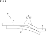
- the sealing member for machine tools of the present invention may have a structure as shown in FIG. 4 .
- FIG. 4 is a side view schematically showing another example of the sealing member for machine tools of the present invention.
- FIG. 5 is a sectional view schematically showing a part of a telescopic cover with the sealing member for machine tools shown in FIG. 4 attached thereto.
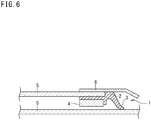
- FIG. 6 is a sectional view schematically showing a part of one example in which a protective member is attached to a conventional telescopic cover.
- a second protective portion 46 is provided at a distal end of a supporting member 41 (an end of a protective portion (first protective portion) 41 b on a side opposite (in the drawing, left side) to a supporting portion 41a).
- the sealing member 40 for machine tools differs from the sealing member 10 for machine tools shown in FIGS. 1A and 1B in that it includes the second protective portion 46, and is the same as the sealing member 10 for machine tools in the remaining configuration.
- an elastic member 42, and an adhesive layer 43 are the same as those of the supporting member 11, the elastic member 12, and the adhesive layer 13 of the sealing member 10 for machine tools shown in FIGS. 1A and 1B , respectively.
- the sealing member 40 for machine tools produces the same effect as that of the sealing member 10 for machine tools shown in FIGS. 1A and 1B , and further, can more reliably prevent chips from coming into contact with the elastic member.
- the sealing member 40 for machine tools shown in FIG. 4 can be used as the telescopic seal or the like.
- the sealing member 40 for machine tools is fixed by bolting (not shown) the supporting member 41 to a lower face of an outer distal end portion of a covering member 45 constituting the telescopic cover.
- the sealing member 40 for machine tools is attached to a position where an outer face 45a of the covering member 45 located below and an end portion of the elastic member 42 are securely in sliding contact with each other.
- the sealing member 40 for machine tools can reliably suppress contacting of chips or the like with the elastic member.
- FIG. 6 there has been proposed a conventional wiper 1 for machine tools in which apart from the wiper 1 for machine tools, a protective member 6 made of metal is attached for preventing chips from coming into contact with a wiper main body 2.
- a further problem is preventing a device (telescopic wiper) from being compact.
- a still further problem is that when the protective member 6 is attached to an upper face of the covering member 5, a step is generated between an upper face of the protective member 6 and the upper face of the covering member 5, so that chips, a coolant or the like might stay in the step portion to hinder operation (cutting process etc.) of a machine tool.
- the sealing member 40 for machine tools can avoid such a problem, and it is also possible to make the sealing member 40 for machine tools compact even when the second protective portion 46 is provided. Additionally, because the second protective portion 46 can be integrated with the supporting member 41 in the sealing member 40 for machine tools, the sealing member 40 for machine tools can be provided at low cost.
- the second protective portion 46 can be integrally produced with the supporting member 41 by further bending the steel plate at another part. Additionally, the second protective portion 46 may be attached to the distal end of the supporting member 41 after being produced separately from the supporting member 41.
- the first protective portion 41 b has a role of protecting a part of the elastic member 42, as well as making the elastic member 42 maintain the curved shape along the bent shape of the supporting member 41.
- a sealing member for machine tools having the shape as shown in FIGS. 1A and 1B was produced by a method set forth below.
- CORONATE 4086 manufactured by Nippon Polyurethane Industry Co., Ltd., a prepolymer of polycaprolactone ester polyol and MDI
- 100 parts by weight of CORONATE 4086 was heated to 70°C to be dissolved, to which 4.90 parts of 1,4-butanediol heated to 70°C and 1.96 parts of trimethylolpropane heated to 70°C were added and stirred to obtain a urethane composition.
- the obtained urethane composition was injected into a metal mold (internal volume: thickness of 1.2 mm, width of 100 mm, length of 230 mm) heated to 125°C and then crosslinked in the mold in an oven maintained at 125°C for 30 minutes. Thereafter, the molded article was taken out and heated in the oven at 110°C for 12 hours to be then crosslinked, thereby producing a urethane sheet.
- the produced sealing member for machine tools has the following size.
- Example 2 Using the same method as in Example 1, a urethane sheet with a thickness of 1.2 mm was produced, and this urethane sheet was cut into a 17.6 mm x 100 mm piece by using an ultrasonic cutter. Thereafter, a corner portion formed by a front face and a side face constituting an edge portion was C-chamfered at 0.6 mm x 45° with an ultrasonic cutter, thereby producing an elastic member.
- the produced sealing member for machine tools has the following size.
- L 21 1.2 mm
- L 22 17.6 mm
- L 23 0.6 mm (regarding the reference signs, see FIG. 2B ).
- Example 2 Using the same method as in Example 1, a urethane sheet with a thickness of 1.2 mm was produced, and this urethane sheet was cut to have a front face size of 17.0 mm x 100 mm and a back face size of 18.2 mm x 100 mm by using an ultrasonic cutter, thereby producing an elastic member.
- the produced sealing member for machine tools has the following size.
- a sealing member for machine tools having the shape as shown in FIG. 7 was produced by a method set forth below.
- CORONATE 4086 manufactured by Nippon Polyurethane Industry Co., Ltd.
- 100 parts by weight of CORONATE 4086 was heated to 70°C to be dissolved, to which 4.90 parts of 1,4-butanediol heated to 70°C and 1.96 parts of trimethylolpropane heated to 70°C were added and stirred.
- the liquid mixture was heated to 125°C and injected into a split metal mold (lower mold) having a section as shown in FIG. 7 in which a supporting member made of brass was placed.
- the liquid mixture was covered with the split metal mold (upper mold) and crosslinked in an oven at 125°C for 30 minutes.
- the molded article was taken out, then crosslinked in the oven at 110°C for 12 hours and further subjected to burring with a cutter knife, thereby making a sealing member for machine tools.
- the produced sealing member for machine tools has the following size.
- L 1 , 2.0 mm
- L 2 1.0 mm
- L 3 2.0 mm
- L 4 10.0 mm
- L 5 16.0 mm
- L 6 3.0 mm
- L 7 1.0 mm (regarding the reference signs, see FIG. 7 ).
- FIG. 8 is a sectional view for explaining a method of measuring slide resistances of the sealing members for machine tools produced in examples and comparative example.
- the saddle 101 As shown in FIG. 8 , after fixing the sealing member 10 for machine tools beneath a saddle 101, the saddle 101 was lowered toward a sliding bed 103, and from a point where the edge portion of the elastic member 12 contacts the sliding bed 103, the saddle 101 (sealing member 10 for machine tools) was further pushed down by 0.5 mm to the side of the sliding bed 103.
- FIG. 9 is a sectional view for explaining a method of evaluating performance of the sealing members for machine tools produced in examples and comparative example.
- the sliding bed 113 was reciprocated a predetermined number of times (up to 20000 times) in a direction of an arrow (in the drawing, in a horizontal direction) at a moving speed of 30 m/min and at a slide stroke of 200 mm, and presence/absence of damages to the elastic member 12, presence/absence of chips having passed through the sliding contact portion, and an amount of chips having passed through the sliding contact portion were checked. Results are shown in Table 2.
- Example 1 As a result, in Example 1, a large volume of chips staying (a large mass of chips) in the vicinity of the edge portion was observed, in Example 2, a small volume of chips staying (a small mass of chips) in the vicinity of the edge portion was observed, and in Example 3, chips were barely found in the vicinity of the edge portion.
- the sealing member for machine tools of the present invention enables contradictory performance to be obtained, that is, the performance of suppressing a slide resistance and ensuring wiper performance in long-time use of the member (when the member is slid repeatedly relative to an opposite material), thereby exhibiting excellent performance as a sealing member for machine tools.
- forming the side face of the elastic member on the contact part side to be oblique relative to the front face enables suppression of staying chips after use of the sealing member for machine tools.
Landscapes
- Engineering & Computer Science (AREA)
- Mechanical Engineering (AREA)
- General Engineering & Computer Science (AREA)
- Life Sciences & Earth Sciences (AREA)
- Forests & Forestry (AREA)
- Sealing Devices (AREA)
Applications Claiming Priority (2)
| Application Number | Priority Date | Filing Date | Title |
|---|---|---|---|
| JP2014021277 | 2014-02-06 | ||
| PCT/JP2015/052476 WO2015119030A1 (fr) | 2014-02-06 | 2015-01-29 | Élément d'étanchéité pour machines-outils |
Publications (3)
| Publication Number | Publication Date |
|---|---|
| EP3103584A1 true EP3103584A1 (fr) | 2016-12-14 |
| EP3103584A4 EP3103584A4 (fr) | 2017-11-29 |
| EP3103584B1 EP3103584B1 (fr) | 2021-01-13 |
Family
ID=53777837
Family Applications (1)
| Application Number | Title | Priority Date | Filing Date |
|---|---|---|---|
| EP15746826.5A Not-in-force EP3103584B1 (fr) | 2014-02-06 | 2015-01-29 | Élément d'étanchéité pour machines-outils |
Country Status (8)
| Country | Link |
|---|---|
| US (1) | US10335910B2 (fr) |
| EP (1) | EP3103584B1 (fr) |
| JP (1) | JP5947471B2 (fr) |
| KR (1) | KR101841186B1 (fr) |
| CN (1) | CN105960309B (fr) |
| ES (1) | ES2861900T3 (fr) |
| TW (1) | TWI636211B (fr) |
| WO (1) | WO2015119030A1 (fr) |
Cited By (1)
| Publication number | Priority date | Publication date | Assignee | Title |
|---|---|---|---|---|
| TWI763899B (zh) * | 2017-08-08 | 2022-05-11 | 日商阪東化學股份有限公司 | 工作機械用密封部材 |
Families Citing this family (6)
| Publication number | Priority date | Publication date | Assignee | Title |
|---|---|---|---|---|
| CN108137770B (zh) * | 2015-10-29 | 2022-03-01 | 阪东化学株式会社 | 工作机械用密封构件 |
| JP6691289B2 (ja) * | 2015-12-23 | 2020-04-28 | 株式会社豊田自動織機 | ロールプレス装置 |
| JP6177464B1 (ja) * | 2015-12-24 | 2017-08-09 | バンドー化学株式会社 | 工作機械用シール部材 |
| JP6174175B1 (ja) * | 2016-02-08 | 2017-08-02 | バンドー化学株式会社 | 工作機械用シール部材 |
| JP6822779B2 (ja) * | 2016-04-15 | 2021-01-27 | バンドー化学株式会社 | 工作機械用シール部材 |
| US20250154877A1 (en) * | 2023-11-15 | 2025-05-15 | Rtx Corporation | Slider seal of gas turbine engine |
Family Cites Families (19)
| Publication number | Priority date | Publication date | Assignee | Title |
|---|---|---|---|---|
| DE1300808B (de) * | 1966-01-11 | 1969-08-07 | Kabelschlepp Gmbh | Abstreifvorrichtung fuer Abdeckplatten von Abdeckvorrichtungen an Fuehrungsbahnen von Werkzeugmaschinen |
| DE7535971U (de) * | 1975-11-12 | 1976-12-09 | Kabelschlepp Gmbh, 5900 Siegen | Abstreifeinrichtung für Gleitbahnen an Werkzeugmaschinen |
| DE3442082A1 (de) * | 1984-11-17 | 1986-05-28 | Wilhelm Carl GmbH & Co, Metalltechnik, 7333 Ebersbach | Abstreifvorrichtung an teleskopartig ineinanderschiebbaren kaesten von schutzabdeckungen |
| JPS6430975A (en) * | 1987-07-24 | 1989-02-01 | Taiho Kogyo Co Ltd | Lip seal device |
| DE3831477A1 (de) * | 1988-09-16 | 1990-03-29 | Cremer Heinrich Hcr Gmbh | Abdeckkasten teleskopartig verkuerz- und verlaengerbarer teleskopabdeckungen von werkzeugmaschinenbahnen |
| JPH0645314Y2 (ja) * | 1988-12-19 | 1994-11-24 | ニッタ株式会社 | 工作機械用スクレーパ |
| JP3443423B2 (ja) * | 1993-06-04 | 2003-09-02 | Nok株式会社 | 密封装置およびその製造方法 |
| JPH11159627A (ja) * | 1997-11-27 | 1999-06-15 | Tokyo Seimitsu Hatsujo Kk | 極薄板状のブレード材 |
| JP3193361B2 (ja) * | 1999-04-07 | 2001-07-30 | ニッタ株式会社 | 工作機械用ワイパー |
| JP2000308944A (ja) | 1999-04-27 | 2000-11-07 | Nitta Ind Corp | 工作機械用ワイパー |
| CN2448516Y (zh) * | 2000-10-26 | 2001-09-19 | 陈佩芳 | 防尘盖刮板结构 |
| JP4745612B2 (ja) * | 2003-01-22 | 2011-08-10 | コマツNtc株式会社 | 工作機械 |
| JP2005246490A (ja) * | 2004-03-01 | 2005-09-15 | Hatakeyama Seisakusho:Kk | 工作機械等の可動部における保護カバー |
| JP2006123126A (ja) * | 2004-10-29 | 2006-05-18 | Okuma Corp | 摺動面保護装置 |
| CN201009114Y (zh) * | 2007-03-23 | 2008-01-23 | 浙江日发数码精密机械股份有限公司 | 机床移动部件防护防屑装置 |
| JP2008264922A (ja) * | 2007-04-19 | 2008-11-06 | Tekutowan:Kk | 極薄金属板のブレードを接着したテレスコピックカバー |
| CN201052581Y (zh) * | 2007-06-08 | 2008-04-30 | 林遂铭 | 防尘护盖的刮刷片 |
| JP2013244572A (ja) * | 2012-05-28 | 2013-12-09 | Tekutowan:Kk | テレスコピックカバーの着脱自在な差込型ブレード |
| DE102013215361A1 (de) * | 2013-08-05 | 2015-02-05 | Aktiebolaget Skf | Dichtungsanordnung |
-
2015
- 2015-01-29 JP JP2015560952A patent/JP5947471B2/ja active Active
- 2015-01-29 US US15/116,188 patent/US10335910B2/en active Active
- 2015-01-29 KR KR1020167024418A patent/KR101841186B1/ko active Active
- 2015-01-29 CN CN201580007128.3A patent/CN105960309B/zh not_active Expired - Fee Related
- 2015-01-29 WO PCT/JP2015/052476 patent/WO2015119030A1/fr not_active Ceased
- 2015-01-29 EP EP15746826.5A patent/EP3103584B1/fr not_active Not-in-force
- 2015-01-29 ES ES15746826T patent/ES2861900T3/es active Active
- 2015-02-04 TW TW104103646A patent/TWI636211B/zh active
Cited By (1)
| Publication number | Priority date | Publication date | Assignee | Title |
|---|---|---|---|---|
| TWI763899B (zh) * | 2017-08-08 | 2022-05-11 | 日商阪東化學股份有限公司 | 工作機械用密封部材 |
Also Published As
| Publication number | Publication date |
|---|---|
| TWI636211B (zh) | 2018-09-21 |
| KR20160117593A (ko) | 2016-10-10 |
| KR101841186B1 (ko) | 2018-03-22 |
| JP5947471B2 (ja) | 2016-07-06 |
| ES2861900T3 (es) | 2021-10-06 |
| CN105960309A (zh) | 2016-09-21 |
| WO2015119030A1 (fr) | 2015-08-13 |
| EP3103584B1 (fr) | 2021-01-13 |
| EP3103584A4 (fr) | 2017-11-29 |
| JPWO2015119030A1 (ja) | 2017-03-23 |
| US20170008140A1 (en) | 2017-01-12 |
| TW201540993A (zh) | 2015-11-01 |
| US10335910B2 (en) | 2019-07-02 |
| CN105960309B (zh) | 2018-12-14 |
Similar Documents
| Publication | Publication Date | Title |
|---|---|---|
| EP3103584B1 (fr) | Élément d'étanchéité pour machines-outils | |
| KR102156248B1 (ko) | 공작 기계용 실 부재 | |
| TWI763899B (zh) | 工作機械用密封部材 | |
| JP6518529B2 (ja) | 工作機械用シール部材の接合方法、及び、工作機械用シール | |
| JP6822779B2 (ja) | 工作機械用シール部材 | |
| TWI719071B (zh) | 工作機械用密封構件 | |
| CN108472782B (zh) | 工作机械用密封部材 | |
| JP2023013080A (ja) | 工作機械用シール部材 | |
| JP2022171122A (ja) | 2液型ウレタン系接着剤組成物 |
Legal Events
| Date | Code | Title | Description |
|---|---|---|---|
| STAA | Information on the status of an ep patent application or granted ep patent |
Free format text: STATUS: THE INTERNATIONAL PUBLICATION HAS BEEN MADE |
|
| PUAI | Public reference made under article 153(3) epc to a published international application that has entered the european phase |
Free format text: ORIGINAL CODE: 0009012 |
|
| STAA | Information on the status of an ep patent application or granted ep patent |
Free format text: STATUS: REQUEST FOR EXAMINATION WAS MADE |
|
| 17P | Request for examination filed |
Effective date: 20160830 |
|
| AK | Designated contracting states |
Kind code of ref document: A1 Designated state(s): AL AT BE BG CH CY CZ DE DK EE ES FI FR GB GR HR HU IE IS IT LI LT LU LV MC MK MT NL NO PL PT RO RS SE SI SK SM TR |
|
| AX | Request for extension of the european patent |
Extension state: BA ME |
|
| DAX | Request for extension of the european patent (deleted) | ||
| A4 | Supplementary search report drawn up and despatched |
Effective date: 20171030 |
|
| RIC1 | Information provided on ipc code assigned before grant |
Ipc: B23Q 11/08 20060101AFI20171024BHEP |
|
| GRAP | Despatch of communication of intention to grant a patent |
Free format text: ORIGINAL CODE: EPIDOSNIGR1 |
|
| STAA | Information on the status of an ep patent application or granted ep patent |
Free format text: STATUS: GRANT OF PATENT IS INTENDED |
|
| INTG | Intention to grant announced |
Effective date: 20200812 |
|
| GRAS | Grant fee paid |
Free format text: ORIGINAL CODE: EPIDOSNIGR3 |
|
| GRAA | (expected) grant |
Free format text: ORIGINAL CODE: 0009210 |
|
| STAA | Information on the status of an ep patent application or granted ep patent |
Free format text: STATUS: THE PATENT HAS BEEN GRANTED |
|
| AK | Designated contracting states |
Kind code of ref document: B1 Designated state(s): AL AT BE BG CH CY CZ DE DK EE ES FI FR GB GR HR HU IE IS IT LI LT LU LV MC MK MT NL NO PL PT RO RS SE SI SK SM TR |
|
| REG | Reference to a national code |
Ref country code: GB Ref legal event code: FG4D |
|
| REG | Reference to a national code |
Ref country code: CH Ref legal event code: EP |
|
| REG | Reference to a national code |
Ref country code: DE Ref legal event code: R096 Ref document number: 602015064732 Country of ref document: DE |
|
| REG | Reference to a national code |
Ref country code: IE Ref legal event code: FG4D |
|
| REG | Reference to a national code |
Ref country code: AT Ref legal event code: REF Ref document number: 1354192 Country of ref document: AT Kind code of ref document: T Effective date: 20210215 |
|
| REG | Reference to a national code |
Ref country code: AT Ref legal event code: MK05 Ref document number: 1354192 Country of ref document: AT Kind code of ref document: T Effective date: 20210113 |
|
| REG | Reference to a national code |
Ref country code: NL Ref legal event code: MP Effective date: 20210113 |
|
| REG | Reference to a national code |
Ref country code: LT Ref legal event code: MG9D |
|
| PG25 | Lapsed in a contracting state [announced via postgrant information from national office to epo] |
Ref country code: PT Free format text: LAPSE BECAUSE OF FAILURE TO SUBMIT A TRANSLATION OF THE DESCRIPTION OR TO PAY THE FEE WITHIN THE PRESCRIBED TIME-LIMIT Effective date: 20210513 Ref country code: LT Free format text: LAPSE BECAUSE OF FAILURE TO SUBMIT A TRANSLATION OF THE DESCRIPTION OR TO PAY THE FEE WITHIN THE PRESCRIBED TIME-LIMIT Effective date: 20210113 Ref country code: GR Free format text: LAPSE BECAUSE OF FAILURE TO SUBMIT A TRANSLATION OF THE DESCRIPTION OR TO PAY THE FEE WITHIN THE PRESCRIBED TIME-LIMIT Effective date: 20210414 Ref country code: FI Free format text: LAPSE BECAUSE OF FAILURE TO SUBMIT A TRANSLATION OF THE DESCRIPTION OR TO PAY THE FEE WITHIN THE PRESCRIBED TIME-LIMIT Effective date: 20210113 Ref country code: HR Free format text: LAPSE BECAUSE OF FAILURE TO SUBMIT A TRANSLATION OF THE DESCRIPTION OR TO PAY THE FEE WITHIN THE PRESCRIBED TIME-LIMIT Effective date: 20210113 Ref country code: BG Free format text: LAPSE BECAUSE OF FAILURE TO SUBMIT A TRANSLATION OF THE DESCRIPTION OR TO PAY THE FEE WITHIN THE PRESCRIBED TIME-LIMIT Effective date: 20210413 Ref country code: NO Free format text: LAPSE BECAUSE OF FAILURE TO SUBMIT A TRANSLATION OF THE DESCRIPTION OR TO PAY THE FEE WITHIN THE PRESCRIBED TIME-LIMIT Effective date: 20210413 Ref country code: NL Free format text: LAPSE BECAUSE OF FAILURE TO SUBMIT A TRANSLATION OF THE DESCRIPTION OR TO PAY THE FEE WITHIN THE PRESCRIBED TIME-LIMIT Effective date: 20210113 |
|
| PG25 | Lapsed in a contracting state [announced via postgrant information from national office to epo] |
Ref country code: SE Free format text: LAPSE BECAUSE OF FAILURE TO SUBMIT A TRANSLATION OF THE DESCRIPTION OR TO PAY THE FEE WITHIN THE PRESCRIBED TIME-LIMIT Effective date: 20210113 Ref country code: AT Free format text: LAPSE BECAUSE OF FAILURE TO SUBMIT A TRANSLATION OF THE DESCRIPTION OR TO PAY THE FEE WITHIN THE PRESCRIBED TIME-LIMIT Effective date: 20210113 Ref country code: RS Free format text: LAPSE BECAUSE OF FAILURE TO SUBMIT A TRANSLATION OF THE DESCRIPTION OR TO PAY THE FEE WITHIN THE PRESCRIBED TIME-LIMIT Effective date: 20210113 Ref country code: LV Free format text: LAPSE BECAUSE OF FAILURE TO SUBMIT A TRANSLATION OF THE DESCRIPTION OR TO PAY THE FEE WITHIN THE PRESCRIBED TIME-LIMIT Effective date: 20210113 Ref country code: PL Free format text: LAPSE BECAUSE OF FAILURE TO SUBMIT A TRANSLATION OF THE DESCRIPTION OR TO PAY THE FEE WITHIN THE PRESCRIBED TIME-LIMIT Effective date: 20210113 |
|
| REG | Reference to a national code |
Ref country code: CH Ref legal event code: PL |
|
| PG25 | Lapsed in a contracting state [announced via postgrant information from national office to epo] |
Ref country code: IS Free format text: LAPSE BECAUSE OF FAILURE TO SUBMIT A TRANSLATION OF THE DESCRIPTION OR TO PAY THE FEE WITHIN THE PRESCRIBED TIME-LIMIT Effective date: 20210513 Ref country code: LU Free format text: LAPSE BECAUSE OF NON-PAYMENT OF DUE FEES Effective date: 20210129 |
|
| REG | Reference to a national code |
Ref country code: BE Ref legal event code: MM Effective date: 20210131 Ref country code: ES Ref legal event code: FG2A Ref document number: 2861900 Country of ref document: ES Kind code of ref document: T3 Effective date: 20211006 |
|
| REG | Reference to a national code |
Ref country code: DE Ref legal event code: R097 Ref document number: 602015064732 Country of ref document: DE |
|
| PG25 | Lapsed in a contracting state [announced via postgrant information from national office to epo] |
Ref country code: SM Free format text: LAPSE BECAUSE OF FAILURE TO SUBMIT A TRANSLATION OF THE DESCRIPTION OR TO PAY THE FEE WITHIN THE PRESCRIBED TIME-LIMIT Effective date: 20210113 Ref country code: MC Free format text: LAPSE BECAUSE OF FAILURE TO SUBMIT A TRANSLATION OF THE DESCRIPTION OR TO PAY THE FEE WITHIN THE PRESCRIBED TIME-LIMIT Effective date: 20210113 Ref country code: CZ Free format text: LAPSE BECAUSE OF FAILURE TO SUBMIT A TRANSLATION OF THE DESCRIPTION OR TO PAY THE FEE WITHIN THE PRESCRIBED TIME-LIMIT Effective date: 20210113 Ref country code: EE Free format text: LAPSE BECAUSE OF FAILURE TO SUBMIT A TRANSLATION OF THE DESCRIPTION OR TO PAY THE FEE WITHIN THE PRESCRIBED TIME-LIMIT Effective date: 20210113 |
|
| PLBE | No opposition filed within time limit |
Free format text: ORIGINAL CODE: 0009261 |
|
| STAA | Information on the status of an ep patent application or granted ep patent |
Free format text: STATUS: NO OPPOSITION FILED WITHIN TIME LIMIT |
|
| PG25 | Lapsed in a contracting state [announced via postgrant information from national office to epo] |
Ref country code: SK Free format text: LAPSE BECAUSE OF FAILURE TO SUBMIT A TRANSLATION OF THE DESCRIPTION OR TO PAY THE FEE WITHIN THE PRESCRIBED TIME-LIMIT Effective date: 20210113 Ref country code: RO Free format text: LAPSE BECAUSE OF FAILURE TO SUBMIT A TRANSLATION OF THE DESCRIPTION OR TO PAY THE FEE WITHIN THE PRESCRIBED TIME-LIMIT Effective date: 20210113 Ref country code: DK Free format text: LAPSE BECAUSE OF FAILURE TO SUBMIT A TRANSLATION OF THE DESCRIPTION OR TO PAY THE FEE WITHIN THE PRESCRIBED TIME-LIMIT Effective date: 20210113 Ref country code: CH Free format text: LAPSE BECAUSE OF NON-PAYMENT OF DUE FEES Effective date: 20210131 Ref country code: LI Free format text: LAPSE BECAUSE OF NON-PAYMENT OF DUE FEES Effective date: 20210131 |
|
| 26N | No opposition filed |
Effective date: 20211014 |
|
| GBPC | Gb: european patent ceased through non-payment of renewal fee |
Effective date: 20210413 |
|
| PG25 | Lapsed in a contracting state [announced via postgrant information from national office to epo] |
Ref country code: GB Free format text: LAPSE BECAUSE OF NON-PAYMENT OF DUE FEES Effective date: 20210413 Ref country code: FR Free format text: LAPSE BECAUSE OF NON-PAYMENT OF DUE FEES Effective date: 20210313 Ref country code: IE Free format text: LAPSE BECAUSE OF NON-PAYMENT OF DUE FEES Effective date: 20210129 Ref country code: AL Free format text: LAPSE BECAUSE OF FAILURE TO SUBMIT A TRANSLATION OF THE DESCRIPTION OR TO PAY THE FEE WITHIN THE PRESCRIBED TIME-LIMIT Effective date: 20210113 |
|
| PG25 | Lapsed in a contracting state [announced via postgrant information from national office to epo] |
Ref country code: SI Free format text: LAPSE BECAUSE OF FAILURE TO SUBMIT A TRANSLATION OF THE DESCRIPTION OR TO PAY THE FEE WITHIN THE PRESCRIBED TIME-LIMIT Effective date: 20210113 |
|
| PG25 | Lapsed in a contracting state [announced via postgrant information from national office to epo] |
Ref country code: IT Free format text: LAPSE BECAUSE OF FAILURE TO SUBMIT A TRANSLATION OF THE DESCRIPTION OR TO PAY THE FEE WITHIN THE PRESCRIBED TIME-LIMIT Effective date: 20210113 |
|
| PG25 | Lapsed in a contracting state [announced via postgrant information from national office to epo] |
Ref country code: IS Free format text: LAPSE BECAUSE OF FAILURE TO SUBMIT A TRANSLATION OF THE DESCRIPTION OR TO PAY THE FEE WITHIN THE PRESCRIBED TIME-LIMIT Effective date: 20210513 |
|
| PG25 | Lapsed in a contracting state [announced via postgrant information from national office to epo] |
Ref country code: BE Free format text: LAPSE BECAUSE OF NON-PAYMENT OF DUE FEES Effective date: 20210131 |
|
| PG25 | Lapsed in a contracting state [announced via postgrant information from national office to epo] |
Ref country code: HU Free format text: LAPSE BECAUSE OF FAILURE TO SUBMIT A TRANSLATION OF THE DESCRIPTION OR TO PAY THE FEE WITHIN THE PRESCRIBED TIME-LIMIT; INVALID AB INITIO Effective date: 20150129 |
|
| PG25 | Lapsed in a contracting state [announced via postgrant information from national office to epo] |
Ref country code: CY Free format text: LAPSE BECAUSE OF FAILURE TO SUBMIT A TRANSLATION OF THE DESCRIPTION OR TO PAY THE FEE WITHIN THE PRESCRIBED TIME-LIMIT Effective date: 20210113 |
|
| PGFP | Annual fee paid to national office [announced via postgrant information from national office to epo] |
Ref country code: ES Payment date: 20240202 Year of fee payment: 10 |
|
| PG25 | Lapsed in a contracting state [announced via postgrant information from national office to epo] |
Ref country code: MK Free format text: LAPSE BECAUSE OF FAILURE TO SUBMIT A TRANSLATION OF THE DESCRIPTION OR TO PAY THE FEE WITHIN THE PRESCRIBED TIME-LIMIT Effective date: 20210113 |
|
| PGFP | Annual fee paid to national office [announced via postgrant information from national office to epo] |
Ref country code: DE Payment date: 20231205 Year of fee payment: 10 |
|
| PG25 | Lapsed in a contracting state [announced via postgrant information from national office to epo] |
Ref country code: MT Free format text: LAPSE BECAUSE OF FAILURE TO SUBMIT A TRANSLATION OF THE DESCRIPTION OR TO PAY THE FEE WITHIN THE PRESCRIBED TIME-LIMIT Effective date: 20210113 |
|
| REG | Reference to a national code |
Ref country code: DE Ref legal event code: R119 Ref document number: 602015064732 Country of ref document: DE |
|
| PG25 | Lapsed in a contracting state [announced via postgrant information from national office to epo] |
Ref country code: DE Free format text: LAPSE BECAUSE OF NON-PAYMENT OF DUE FEES Effective date: 20250801 |
|
| PG25 | Lapsed in a contracting state [announced via postgrant information from national office to epo] |
Ref country code: TR Free format text: LAPSE BECAUSE OF FAILURE TO SUBMIT A TRANSLATION OF THE DESCRIPTION OR TO PAY THE FEE WITHIN THE PRESCRIBED TIME-LIMIT Effective date: 20210113 |
|
| REG | Reference to a national code |
Ref country code: ES Ref legal event code: FD2A Effective date: 20260305 |