EP3099052B1 - Bildverarbeitungsvorrichtung, bildverarbeitungsverfahren und speichermedium - Google Patents
Bildverarbeitungsvorrichtung, bildverarbeitungsverfahren und speichermedium Download PDFInfo
- Publication number
- EP3099052B1 EP3099052B1 EP16171565.1A EP16171565A EP3099052B1 EP 3099052 B1 EP3099052 B1 EP 3099052B1 EP 16171565 A EP16171565 A EP 16171565A EP 3099052 B1 EP3099052 B1 EP 3099052B1
- Authority
- EP
- European Patent Office
- Prior art keywords
- value
- colour
- patches
- lab
- patch
- Prior art date
- Legal status (The legal status is an assumption and is not a legal conclusion. Google has not performed a legal analysis and makes no representation as to the accuracy of the status listed.)
- Active
Links
Images







Classifications
-
- H—ELECTRICITY
- H04—ELECTRIC COMMUNICATION TECHNIQUE
- H04N—PICTORIAL COMMUNICATION, e.g. TELEVISION
- H04N1/00—Scanning, transmission or reproduction of documents or the like, e.g. facsimile transmission; Details thereof
- H04N1/46—Colour picture communication systems
- H04N1/50—Picture reproducers
-
- H—ELECTRICITY
- H04—ELECTRIC COMMUNICATION TECHNIQUE
- H04N—PICTORIAL COMMUNICATION, e.g. TELEVISION
- H04N1/00—Scanning, transmission or reproduction of documents or the like, e.g. facsimile transmission; Details thereof
- H04N1/46—Colour picture communication systems
- H04N1/56—Processing of colour picture signals
- H04N1/60—Colour correction or control
- H04N1/6002—Corrections within particular colour systems
- H04N1/6008—Corrections within particular colour systems with primary colour signals, e.g. RGB or CMY(K)
-
- G—PHYSICS
- G06—COMPUTING OR CALCULATING; COUNTING
- G06F—ELECTRIC DIGITAL DATA PROCESSING
- G06F3/00—Input arrangements for transferring data to be processed into a form capable of being handled by the computer; Output arrangements for transferring data from processing unit to output unit, e.g. interface arrangements
- G06F3/12—Digital output to print unit, e.g. line printer, chain printer
- G06F3/1201—Dedicated interfaces to print systems
- G06F3/1202—Dedicated interfaces to print systems specifically adapted to achieve a particular effect
- G06F3/1203—Improving or facilitating administration, e.g. print management
- G06F3/1208—Improving or facilitating administration, e.g. print management resulting in improved quality of the output result, e.g. print layout, colours, workflows, print preview
-
- G—PHYSICS
- G06—COMPUTING OR CALCULATING; COUNTING
- G06F—ELECTRIC DIGITAL DATA PROCESSING
- G06F3/00—Input arrangements for transferring data to be processed into a form capable of being handled by the computer; Output arrangements for transferring data from processing unit to output unit, e.g. interface arrangements
- G06F3/12—Digital output to print unit, e.g. line printer, chain printer
- G06F3/1201—Dedicated interfaces to print systems
- G06F3/1202—Dedicated interfaces to print systems specifically adapted to achieve a particular effect
- G06F3/1203—Improving or facilitating administration, e.g. print management
- G06F3/1204—Improving or facilitating administration, e.g. print management resulting in reduced user or operator actions, e.g. presetting, automatic actions, using hardware token storing data
-
- H—ELECTRICITY
- H04—ELECTRIC COMMUNICATION TECHNIQUE
- H04N—PICTORIAL COMMUNICATION, e.g. TELEVISION
- H04N1/00—Scanning, transmission or reproduction of documents or the like, e.g. facsimile transmission; Details thereof
- H04N1/0035—User-machine interface; Control console
- H04N1/00405—Output means
- H04N1/00408—Display of information to the user, e.g. menus
- H04N1/0044—Display of information to the user, e.g. menus for image preview or review, e.g. to help the user position a sheet
- H04N1/00442—Simultaneous viewing of a plurality of images, e.g. using a mosaic display arrangement of thumbnails
- H04N1/00453—Simultaneous viewing of a plurality of images, e.g. using a mosaic display arrangement of thumbnails arranged in a two dimensional array
-
- H—ELECTRICITY
- H04—ELECTRIC COMMUNICATION TECHNIQUE
- H04N—PICTORIAL COMMUNICATION, e.g. TELEVISION
- H04N1/00—Scanning, transmission or reproduction of documents or the like, e.g. facsimile transmission; Details thereof
- H04N1/0035—User-machine interface; Control console
- H04N1/00405—Output means
- H04N1/00485—Output means providing a hardcopy output to the user, e.g. print out
-
- H—ELECTRICITY
- H04—ELECTRIC COMMUNICATION TECHNIQUE
- H04N—PICTORIAL COMMUNICATION, e.g. TELEVISION
- H04N1/00—Scanning, transmission or reproduction of documents or the like, e.g. facsimile transmission; Details thereof
- H04N1/46—Colour picture communication systems
- H04N1/56—Processing of colour picture signals
- H04N1/60—Colour correction or control
- H04N1/6011—Colour correction or control with simulation on a subsidiary picture reproducer
- H04N1/6013—Colour correction or control with simulation on a subsidiary picture reproducer by simulating several colour corrected versions of the same image simultaneously on the same picture reproducer
-
- H—ELECTRICITY
- H04—ELECTRIC COMMUNICATION TECHNIQUE
- H04N—PICTORIAL COMMUNICATION, e.g. TELEVISION
- H04N1/00—Scanning, transmission or reproduction of documents or the like, e.g. facsimile transmission; Details thereof
- H04N1/46—Colour picture communication systems
- H04N1/56—Processing of colour picture signals
- H04N1/60—Colour correction or control
- H04N1/6016—Conversion to subtractive colour signals
- H04N1/6019—Conversion to subtractive colour signals using look-up tables
-
- H—ELECTRICITY
- H04—ELECTRIC COMMUNICATION TECHNIQUE
- H04N—PICTORIAL COMMUNICATION, e.g. TELEVISION
- H04N1/00—Scanning, transmission or reproduction of documents or the like, e.g. facsimile transmission; Details thereof
- H04N1/46—Colour picture communication systems
- H04N1/56—Processing of colour picture signals
- H04N1/60—Colour correction or control
- H04N1/62—Retouching, i.e. modification of isolated colours only or in isolated picture areas only
- H04N1/622—Retouching, i.e. modification of isolated colours only or in isolated picture areas only with simulation on a subsidiary picture reproducer
-
- H—ELECTRICITY
- H04—ELECTRIC COMMUNICATION TECHNIQUE
- H04N—PICTORIAL COMMUNICATION, e.g. TELEVISION
- H04N1/00—Scanning, transmission or reproduction of documents or the like, e.g. facsimile transmission; Details thereof
- H04N1/46—Colour picture communication systems
- H04N1/64—Systems for the transmission or the storage of the colour picture signal; Details therefor, e.g. coding or decoding means therefor
- H04N1/648—Transmitting or storing the primary (additive or subtractive) colour signals; Compression thereof
Definitions
- the present invention relates to an image processing apparatus and an image processing method, in particular, for updating a color conversion table based on a signal value corresponding to a color that is visually selected as a target color from a printed chart.
- a color desired to be adjusted is extracted from an image of a POP display, and patches of the respective neighboring colors of the extracted color are generated.
- a chart where the generated patches are arranged is printed, and a user visually selects the patch of a desired color from the printed patches.
- a table for color conversion is updated according to the color of the selected patch (see Japanese Patent Application Laid-Open No. 2011-114717 ).
- EP2306700 discusses a method of designating color comparing conditions (which can include a type of observational light source) for a color chart.
- Image data is generated to print first, second and third color charts in which color patches having colors corresponding respectively to different variables of the designated color comparing conditions are disposed adjacent to each other.
- EP2434745 discusses a color patch which is extracted as a candidate patch from within a color chart.
- the patch is colorimetrically measured and a color value is acquired.
- a corresponding position on the color chart responsive to the color value of the designated color is calculated.
- Instruction mark images indicative of the calculated corresponding position are displayed respectively, together with a simulating image, in which a layout of multiple color patches on the color chart is simulated.
- an image processing apparatus as specified in claims 1 to 11.
- an image processing method as specified in claim 12.
- a computer-readable storage medium for causing a computer to execute an image processing method as specified in claim 13.
- Fig. 1 is a block diagram illustrating an example of a configuration of an image forming system including an image processing apparatus according to a first exemplary embodiment of the present invention.
- This image forming system includes a network 101, a computer 102, a display 103, and a printer 106.
- the printer 106 includes a printer controller 104 and a printer engine 105.
- the computer 102 and the printer 106 can communicate via the network 101.
- the computer 102 can transmit a print instruction to the printer 106, and receive information of the printer 106.
- the computer 102 and the display 103 are connected to each other, and the computer 102 causes screen output by transmitting screen information of a running application to the display 103.
- the printer controller 104 and the printer engine 105 are connected to each other, and the printer controller 104 causes printer output by transmitting a control signal to the printer engine 105.
- Fig. 2A is a block diagram illustrating a physical configuration of the computer 102.
- the computer 102 includes an internal bus 201, a central processing unit (CPU) 202, a random access memory (RAM) 203, an external storage apparatus 204, a display interface 205, an external input apparatus 206, and a network interface 207.
- the CPU 202, the RAM 203, the external storage apparatus 204, the display interface 205, the external input apparatus 206, and the network interface 207 are connected to the network 101, and perform data communications with the printer 106.
- the CPU 202 When the computer 102 is activated, the CPU 202 reads an application execution program from the external storage apparatus 204 into the RAM 203, and executes the read program.
- the program being executed by the CPU 202 starts transmitting screen display data to the display interface 205, thereby outputting a screen on the display 103. Further, the CPU 202 monitors user input information provided from the external input apparatus 206. When the user input information is input, the CPU 202 executes processing defined in the program and corresponding to the user input information.
- Fig. 2B is a block diagram illustrating a physical configuration of the printer controller 104.
- the printer controller 104 includes an internal bus 208, a CPU 209, a RAM 210, an external storage apparatus 211, a network interface 212, an engine interface 213, and an input apparatus 214.
- the CPU 209, the RAM 210, the external storage apparatus 211, the network interface 212, the engine interface 213, and the input apparatus 214 perform data communicates with each other via the internal bus 208.
- the printer controller 104 When the printer controller 104 is activated, the CPU 209 reads an execution program from the external storage apparatus 211 into the RAM 210, and executes this program.
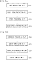
- Fig. 3A is a block diagram illustrating a module configuration of the program executed by the CPU 202.
- the modules of the program executed by the CPU 202 include a data acquisition unit 301, a chart data generation unit 302, a print processing unit 303, and a color update processing unit 304.
- the data acquisition unit 301 acquires an adjustment-color value (an adjustment value) to be adjusted, table data necessary for chart generation, and a color conversion table.
- the adjustment value is assumed to be a value in a color space used in a typical monitor. Examples of the color space used in the monitor include a standard red green blue (sRGB) color space and an Adobe RGB color space. In this description, the adjustment value is assumed to be a value in the sRGB color space.
- the color conversion table is assumed to be a table for converting the sRGB into a device-dependent RGB (devRGB) color space. This table indicates a relationship between the color value of a color displayed by the display 103 and the color value of a color formed by the printer 106.
- the table data is necessary for processing for updating the color conversion table.
- This table data is assumed to be a devRGB-to-Lab conversion table.
- the Lab is a perceptually uniform color space, which is a three-dimensional color space formed to be device-independent considering the visual properties of humans.
- each color space to be used is not limited to those described above.
- the chart data generation unit 302 generates chart data, based on the data acquired by the data acquisition unit 301.
- the print processing unit 303 performs print control processing, which is necessary for printing the chart data generated by the chart data generation unit 302, in the printer 106.
- the print processing unit 303 converts the chart data into a color space usable by the printer 106, and transmits the result of this conversion to a rendering processing unit 305 to be described below.
- the color update processing unit 304 acquires a target color value (a target value), and updates the color conversion table, by using the acquired target value, and the adjustment value as well as the color conversion table acquired by the data acquisition unit 301.
- Fig. 3B is a block diagram illustrating a module configuration of the program executed by the CPU 209.
- the modules of the program executed by the CPU 209 include the rendering processing unit 305, a color conversion unit 306, a binarization processing unit 307, and an engine control unit 308.
- the rendering processing unit 305 renders image data such as the chart data converted by the print processing unit 303, in an image memory (not illustrated).
- the color conversion unit 306 converts the image data rendered in the image memory, into image data (cyan, magenta, yellow, and key or black (CMYK)) corresponding to color materials used by the printer engine 105.
- CMYK key or black
- the binarization processing unit 307 converts the image data resulting from the conversion by the color conversion unit 306 into binary image data, by performing image forming processing such as screening processing and error diffusion processing.
- the binarization processing unit 307 then outputs the binary image data to the engine control unit 308.
- the engine control unit 308 outputs an instruction for performing printer engine control to the engine interface 213, based on the binary image data resulting from the conversion by the binarization processing unit 307.
- the printer engine 105 forms an image on a paper surface, as an ink image or toner image.
- the target color is visually selected from a printed chart, and the color conversion table is updated based on the target value corresponding to the target color.
- the CPU 202 of the computer 102 performs processing in step S401, step S402, and step S404 to step S406, and the CPU 209 of the printer controller 104 performs processing in step S403, in the processing illustrated in Fig. 4 .
- the data acquisition unit 301 acquires the adjustment-color value (the adjustment value) to be adjusted, the table data, and the color conversion table necessary for chart generation.
- the adjustment value may be acquired by preparing beforehand sRGB combinations corresponding to some colors, and allowing a user to select an arbitrary color combination (an sRGB combination) from the prepared combinations.
- a mechanism capable of allowing the user to input an sRGB value corresponding to the adjustment color may be adopted.
- image data of, e.g., a POP display including a color desired to be changed
- an sRGB value corresponding to the adjustment color may be acquired from the image data, to use the acquired sRGB value as the adjustment value.
- the user may specify a color desired to be changed (the adjustment color), from an image displayed on the display 103. Subsequently, the sRGB value of the specified color may be automatically acquired to be used as the adjustment value.
- the color conversion table is a table held in the external storage apparatus 204 of the computer 102 or the external storage apparatus 211 of the printer 106, to be used in printing of image data.
- the table necessary for the chart generation is selected from the devRGB-to-Lab conversion tables that are prepared beforehand according to the types of printer.
- the devRGB-to-Lab conversion tables according to the types of printer are each created as follows, for example. First, a chart dedicated to table creation is printed by a printer. Next, a Lab value is acquired by measuring the printed chart, and a devRGB value is associated with the acquired Lab value.
- step S402 the chart data generation unit 302 generates the chart data based on the data acquired in step S401. This chart generation will be described below in detail.
- step S403 the print processing unit 303 prints the chart, based on the chart data generated in step S402. This print processing will be described below in detail.
- the color update processing unit 304 then performs step S404 to step S406.
- step S404 first, the user selects the patch of the target color from the chart printed in step S403.
- the color update processing unit 304 acquires the target value corresponding to this color, by receiving the result of the selection made by the user.
- the target value is acquired as follows, for example.
- First, an image of the chart printed using the chart data (sRGB) generated in step S402 is displayed on the display 103.
- the displayed image of the chart and the printed chart are identical in terms of patch array.
- the user selects a patch from the chart displayed on the display 103.
- the selected patch is at the same position as the position of a patch desired to be selected as the target color for the adjustment color from the patches on the printed chart.
- the target value corresponding to the adjustment value is thereby acquired.
- the coordinate position of each patch may be added to the chart when the chart is printed, and the coordinate position of the selected patch may be input.
- the displayed image of the chart and the printed chart may not be identical in terms of patch array.
- step S405 color updating processing is performed using the adjustment value and the color conversion table acquired in step S401, and the target value acquired in step S404.
- a part of the color conversion table is updated in such a manner that an output value when the adjustment value is converted using the color conversion table is identical to an output value when the target value is converted using the color conversion table. For example, assume that the sRGB value of the adjustment value is (150, 0, 0), and the devRGB value of the output value resulting from color conversion using the color conversion table before update is (120, 0, 0).
- the color conversion table for sRGB (an arbitrary color space) to devRGB (a device-dependent color space) conversion is updated, in such a manner that the output value of the sRGB value (150, 0, 0) of the adjustment value is identical to the devRGB value (120, 15, 0) of the output value after the color conversion.
- Saturated color or gradation steps may occur in the color conversion table after update, depending on the target value. Therefore, smoothing processing can be performed for the neighboring colors of the updated part of the color conversion table.
- step S406 the color conversion table updated in step S405 is stored into the external storage apparatus 204 of the computer 102 or the external storage apparatus 211 of the printer 106.
- the updated color conversion table may be stored by overwriting the color conversion table acquired in step S401, or may be stored as a different color conversion table.
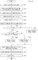
- step S402 the chart data generation processing in step S402 will be described in detail with reference to Fig. 6 .
- the chart data generation unit 302 performs the chart data generation processing and thus performs processing in all of steps in Fig. 6 .
- step S601 the adjustment value acquired in step S401 is acquired.
- step S602 the color conversion table and the table data necessary for the chart generation acquired in step S401 are acquired.
- a table for converting each of the adjustment value and the target value into the Lab value (a sRGB-to-Lab conversion table) is generated.
- the sRGB-to-Lab conversion table is generated by combining the color conversion table (the sRGB-to-devRGB conversion table) with the table necessary for the chart generation (the devRGB-to-Lab conversion table), which are acquired in step S602.
- the combining is performed using, for example, interpolation calculation.
- interpolation calculation when a value not defined in a calculation table is input, interpolation is performed using a value that is defined in the calculation table and close to the input value. Examples of the interpolation calculation include tetrahedral interpolation.
- interpolation calculation is performed using four values, which are defined in a calculation table and close to an input value.
- an input is assumed to be a devRGB value in the sRGB-to-devRGB conversion table, and the sRGB-to-Lab conversion table is generated by performing calculation for the tetrahedral interpolation, using the devRGB-to-Lab conversion table as the calculation table.
- the tetrahedral interpolation is used for the combining, but the combining is not limited to this interpolation. Any method may be used if the sRGB-to-Lab conversion table can be generated from the sRGB-to-devRGB conversion table and the devRGB-to-Lab conversion table.
- step S604 the adjustment value is converted into the Lab value.
- the sRGB value of the adjustment value is converted into the Lab, by using the sRGB-to-Lab conversion table generated in step S603. This conversion is executed by performing the tetrahedral interpolation, using the input as the adjustment value, and the sRGB-to-Lab conversion table as the calculation table.
- step S605 based on the Lab value of the adjustment value generated in step S604, a Lab value for generating a patch to be a candidate (a candidate patch) for selecting the target value is generated.
- the Lab value of the candidate patch is generated by combining values that are obtained by converting each of L, a, and b values stepwise, based on the Lab value of the adjustment value.
- the L, a, and b values are generated using the following expression 1.
- candidate-patch Lab values are generated. These candidate-patch Lab values each correspond to a neighboring value of the Lab value of the adjustment value, and the color of each of the candidate patches is expressed by a neighboring color of the adjustment color.
- the patch of the neighboring color will be hereinafter referred to as "candidate patch”.
- step S606 chroma and hue of the adjustment value are calculated from the adjustment value (the Lab value).
- H represents the hue
- a and b represent the a and b values of the Lab
- PI represents the ratio of the circumference of a circle to the diameter
- atan represents calculation of an arc tangent.
- step S607 to step S611 correspond to processing concerning an arrangement of the candidate patches generated in step S605.
- the arrangement of the candidate patches in the chart are determined according to the color value of the adjustment color, for making it easy to select a patch having the target color from the candidate patches.
- the target color is visually selected by the user, as described above with reference to step S404 in Fig. 4 . Therefore, the candidate patches can be arranged considering the visual properties of humans.
- the visual properties of humans include being more insensitive to a change in the chroma than to a change in the luminance, being more insensitive to a change in the hue than to a change in the chroma, and being more insensitive to a change as the luminance is higher.
- step S607 it is determined whether the L value of the adjustment value (the Lab value) is equal to or higher than a threshold.
- a predetermined value is used as the threshold. For example, when the L value is 0 to 100 and the higher value is brighter, the determination is performed using a value of 50 as the threshold.
- the threshold may be set beforehand, or may be dynamically set according to, for example, the features of an image such as a POP display desired to be changed in color or the properties of a printer that performs printing.
- step S608 it is determined whether the adjustment value (the Lab value) is close to an a-axis in the Lab color space. This determination is performed using the hue (H) calculated in step S606. As illustrated in Fig. 7 , the hue is expressed in such a form that, when the a-axis is assumed to be a horizontal axis and a b-axis is assumed to be a vertical axis, the value increases counterclockwise from the a-axis that is 0 degrees. Therefore, the adjustment value is determined to be close to the a-axis, if a condition of 0° ⁇ H ⁇ 45°, or 135° ⁇ H ⁇ 225°, or 315° ⁇ H ⁇ 360° is satisfied.
- step S609 the patch arrangement is performed using an L-b plane as a reference.
- the patch arrangement using the L-b plane as the reference will be described.
- n 1, i.e., 27 patches in total are generated.
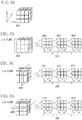
- each of the Lab values of the respective candidate patches generated in step S605 can be expressed by an image of each of small cubes forming a cube 801 in the Lab color space.
- the cube 801 is segmented by a plane perpendicular to any one of the b-axis, the a-axis, and the L-axis, such as a plane 802 in Fig. 8B , a plane 804 in Fig. 8C , and a plane 806 in Fig. 8D .
- the candidate patches forming one plane are arranged as one patch group, and the patches are arranged by aligning the patch groups to form each of arrangements 803, 805, and 807.
- the chart data allowing such a patch arrangement is generated.
- the patch arrangement using the L-b plane as the reference is as follows. First, the candidate patches expressed by a cube (a three-dimensional form) in the Lab color space are segmented by a plane perpendicular to the a-axis. Next, the candidate patches in the L-b plane are formed as one patch group, and patch groups each corresponding to such a patch group are arranged in the chart.
- Patch groups 808 to 810 include the candidate patches in an L-a plane.
- the patch groups 808 and 810 each have values obtained by moving each candidate patch of the patch group 809 along the b-axis direction.
- patch groups 811 to 813 include candidate patches in the L-b plane.
- the patch groups 811 and 813 each have values obtained by moving each candidate patch of the patch group 812 along the a-axis direction.
- patch groups 814 to 816 include candidate patches in an a-b plane.
- the patch groups 814 and 816 each have values obtained by moving each candidate patch of the patch group 815 along the L-axis direction.
- Fig. 11 is a diagram illustrating the candidate patches in the a-b plane of the Lab space.
- Fig. 11 illustrates two examples. One is a case where the adjustment value (the Lab value) is close to the a-axis (candidate patches 1101), and the other is a case where the adjustment value (the Lab value) is close to the b-axis (candidate patches 1102).
- the adjustment value the Lab value
- the chroma is determined based on a distance from an origin point, which is the intersection of the a-axis and the b-axis in the a-b plane, to a patch. Further, in Fig. 11 , the hue is determined, based on the angle of a patch when the a-axis in the a-b plane is assumed to be zero degrees.
- the candidate patches 1101 in Fig. 11 represent an example of the candidate patches when the adjustment value (the Lab value) is close to the a-axis.
- the distance from the origin point greatly varies between the adjacent patches among the patches aligned in a direction parallel to the a-axis.
- the angle from the a-axis greatly varies between the adjacent patches among the patches aligned in a direction parallel to the b-axis.
- a change in the chroma is large between the adjacent patches among the patches aligned in the direction parallel to the a-axis. Further, a change in the hue is large between the adjacent patches among the patches aligned in the direction parallel to the b-axis.
- the patches in which a change is more difficult to recognize can be arranged closer, because it is easier for the user to visually recognize a color difference between the patches in this arrangement.
- the adjustment value (the Lab value) is close to the a-axis
- the candidate patches having a change in the b-axis are arranged closer.
- the patch arrangement is performed using the L-b plane as the reference.
- step S610 the patch arrangement is performed using the L-a plane as the reference. This arrangement is performed in a manner similar to that in the case where the arrangement is performed using the L-b plane as the reference.
- the candidate patches 1102 illustrated in Fig. 11 represent an example of the candidate patches in the case where the adjustment value (the Lab value) is close to the b-axis.
- the distance from the origin point greatly varies between the patches aligned in the direction parallel to the b-axis, and the angle from the a-axis greatly varies between the patches aligned in the direction parallel to the a-axis. Therefore, when the adjustment value (the Lab value) is close to the b-axis, a change in the chroma is large in the direction parallel to the b-axis, and a change in the hue is large in the direction parallel to the a-axis, as represented by the candidate patches 1102 in Fig. 11 . As described above, it is more difficult to recognize a change in the hue than to recognize a change in the chroma.
- the adjustment value (the Lab value) is close to the b-axis
- the candidate patches having a change in the a-axis are arranged closer.
- the patch arrangement is performed using the L-a plane as the reference.
- step S607 If it is determined that the L value of the adjustment value (the Lab value) is not equal to or higher than the threshold (NO in step S607), the processing proceeds to step S611.
- step S611 the patch arrangement is performed using the a-b plane as the reference. This arrangement is performed in a manner similar to that in the case where the arrangement is performed using the L-b plane as the reference.
- the a-b plane is used as the reference when it is determined that the L value is not equal to or higher than the threshold, i.e., when the L value is low. This is because it is relatively easy to recognize a change in the L value when the L value is low, even if the patches are distant. Therefore, the a-b plane, in which mainly the chroma and the hue vary, is used as the reference.
- step S612 candidate-patch exclusion processing is performed.
- the candidate patch falling outside a printer color reproduction range is excluded from the candidate patches generated and arranged in or before step S611.
- the candidate patches are generated in the Lab color space, i.e., in the device-independent color space. Therefore, the candidate patch falling outside the printer color reproduction range may be generated.
- the candidate patch falling outside the printer color reproduction range is rounded to the color range reproducible by the printer. Therefore, in the present exemplary embodiment, such a patch is excluded.
- the candidate-patch exclusion processing may be performed in any method, if the method prevents the candidate patch, which is determined to fall outside the color reproduction range, from being selected as the target value.
- determination as to whether the candidate patch falls outside the color reproduction range is performed based on whether the Lab value of each candidate patch is included in the range of the Lab values of the devRGB-to-Lab conversion table acquired in step S602. Specifically, this determination is performed by determining whether the Lab value of the candidate patch is present in a tetrahedron in the Lab color space.
- the tetrahedron is formed of an arbitrary Lab value and three neighboring Lab values thereof in the devRGB-to-Lab conversion table. Whether the candidate patch is present is determined for all the tetrahedrons that can be formed using the Lab values of the devRGB-to-Lab conversion table. If the candidate patch is determined to be absent in all the tetrahedrons, this candidate patch is determined to fall outside the color reproduction range.
- this determination is performed by the method using the tetrahedron that can be formed from the devRGB-to-Lab conversion table.
- any method may be employed, if the method can extract the printer color reproduction range and determine whether the candidate patch falls outside the color reproduction range.
- step S613 the candidate patches generated and arranged as the Lab values are each converted into the sRGB value.
- the conversion from the Lab value to the sRGB value is performed by signal search processing using the sRGB-to-Lab conversion table generated in step S603.
- the signal search processing first, the tetrahedral interpolation is performed, using all the signal value combinations of the sRGB values of 0 to 255 as the input, and using the sRGB-to-Lab conversion table as the calculation table. Of all the Lab values calculated by the tetrahedral interpolation, a Lab value closest to the Lab value of an arbitrary candidate patch is extracted.
- the sRGB value corresponding to the extracted Lab value is then determined to be the sRGB value of the candidate patch.
- the candidate patches generated and arranged as the Lab values are each converted into the sRGB value, by performing this signal search processing for all the candidate patches.
- the signal search processing is used, but the conversion is not limited to this processing.
- the Lab value of the candidate patch may be converted into the sRGB value, by creating a reverse table of the sRGB-to-Lab conversion table (i.e., a Lab-to-sRGB conversion table).
- step S614 the candidate patches of the sRGB values generated in step S613 are transmitted to the print processing unit 303, as one chart.
- step S501 the chart data generation unit 302 performs color conversion of the chart data generated in step S402, by using the color conversion table acquired in step S401.
- the chart data generation unit 302 converts the chart data from the sRGB into the devRGB color space.
- the chart data generation unit 302 then transmits the chart data after the color conversion, to the rendering processing unit 305.
- step S502 the rendering processing unit 305 renders the image data in the image memory, according to the chart data received from the chart data generation unit 302.
- the rendering processing unit 305 then transmits the image data rendered in the image memory, to the color conversion unit 306.
- step S503 the color conversion unit 306 converts the image data into the CMYK data, by using a look-up table (LUT) for conversion from the devRGB stored beforehand in the external storage apparatus 211 to the CMYK.
- the color conversion unit 306 then transmits the CMYK data to the binarization processing unit 307.
- step S504 the binarization processing unit 307 converts the received chart data resulting from the color conversion into the binary image data, by performing the image forming processing such as the screening processing and the error diffusion processing.
- the binarization processing unit 307 then outputs the binary image data to the engine control unit 308.
- step S505 the engine control unit 308 outputs the instruction for performing the printer engine control to the engine interface 213, based on the binary image data resulting from the conversion in step S504, to the engine interface 213.
- This allows the printer engine 105 to form the chart where the candidate patches are printed on a paper sheet as an ink image or toner image. The user visually selects the patch having the desired color from the patches printed on this chart. The color conversion table allowing the adjustment color to be the target color is then generated, assuming the color of the selected patch to be the target color.
- the patches are arranged to allow easy recognition of a color variation between the patches printed on the chart, even if the color desired to be adjusted is any color. Therefore, the chart, from which the user can easily select the patch of the desired color, can be printed.
- the computer 102 in Fig. 1 performs the processing except for the chart print processing (step S403) of the present exemplary embodiment.
- the printer controller 104 alone may perform these processing.
- the patch arrangement is performed using any one of the L-a plane, the L-b plane, and the a-b plane in the Lab color space, as the reference.
- the patches are arranged at distant positions, in the direction parallel to the b-axis if the L-a plane is used, the a-axis if the L-b plane is used, and the L-axis if the a-b plane is used.
- the total number of the patches is on the order of 27 as in the example described in the first exemplary embodiment.
- the larger the number of the patches to be generated is the larger the number of the patches forming one patch group is, and therefore, the longer the distance between the patch groups is. This makes it more difficult to recognize a color variation between the patches. Therefore, if the number of the patches is large, the patches are arranged in such a manner that the luminance, the chroma, and the hue each change stepwise based on the adjustment color, for allowing the user to compare differences between the patches easily.
- the patches are arranged in such a manner that the L, a, and b values each change stepwise, based on the adjustment value (the Lab value). This makes it easy to select the patch of the desired color even if the total number of the patches is large. A method for thus arranging the patches will be described below.
- Step S901 to step S906 are similar to step S601 to step S606 in Fig. 6 and therefore will not be described.
- step S907 it is determined whether the Lab value of the adjustment value is close to the a-axis in the Lab color space. This determination is performed based on the hue of the adjustment value, as with the processing in step S608 in Fig. 6 .
- step S908 the patch arrangement is performed based on the L-b plane.
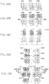
- a method for arranging the patches based on the L-b plane will be described with reference to Figs. 10A to 10E .
- the patch arrangement is performed based on the L-b plane in a manner similar to step S609 of the first exemplary embodiment, as illustrated in Fig. 10A .
- each of planes 1001, 1002, and 1003 in Fig. 10A is segmented based on the patch having the same L value as the L value of the adjustment value.
- a space equivalent to one patch is inserted between the segmented patches, as illustrated in Fig. 10B .
- the space to be inserted is not limited to the size of one patch, and may be changed according to, for example, the total number of the patches.
- a patch group (each of patch groups 1004, 1005, and 1006), which includes the patch having the same L value as the L value of the adjustment value, and the patches having the L values in a direction positive with respect to this L value, is generated as a block.
- a patch group (each of patch groups 1007, 1008, and 1009), which includes the patch having the same L value as the L value of the adjustment value, and the patches having the L values in a direction negative with respect to this L value, is also generated as a block.
- the patches are arranged by inserting the space for one patch between the generated blocks.
- the generated patch groups (the patch groups 1004, 1005, 1006, 1007, 1008, and 1009) are then individually rotated clockwise by 90 degrees, as illustrated in Fig. 10C .
- the individually rotated patch groups are then rotated counterclockwise by 90 degrees as one set (a set 1010), as illustrated in Fig. 10D .
- a patch group (each of patch groups 1017, 1018, 1019, and 1020) is generated as a small block, by segmenting the patch group (each of the patch groups 1012 and 1015) having the same a value as the a value of the adjustment value, based on the patch having the same b value as the b value of the adjustment value.
- a patch having the same value as the adjustment value is inserted between the generated patch groups (i.e., between the patch groups 1017 and 1018, and between the patch groups 1019 and 1020).
- the patch to be inserted is assumed to have a size of one patch in the b direction and the number of patches (two) equal to one side of the small block in the L direction.
- the patch to be inserted is not limited to the above-described size, and may be changed according to, for example, the total number of the patches.
- the patch having the same L value as the L value of the adjustment value and the patch having the L value positive in the L direction with respect to this L value are interchanged.
- the patch having the same L value as the L value of the adjustment value and the patch having the L value negative in the L direction with respect to this L value are interchanged. In this way, the patch arrangement is performed based on the L-b plane, as illustrated in Fig. 10E .
- step S909 the patch arrangement is performed based on the L-a plane.
- the patch arrangement based on the L-a plane is performed in a manner similar to that in the patch arrangement based on the L-b plane.
- Step S910 to step S912 are similar to step S612 to step S614 in Fig. 6 and therefore will not be described.
- the patches can be arranged in such a manner that the luminance, the chroma, and the hue change stepwise, based on the color patch of the adjustment value.
- the patches can be arranged to achieve a gradual visual change from the color patch of the adjustment value in the center. Therefore, the patch of the desired color can be selected, even if the number of the generated patches is large.
- the computer 102 in Fig. 1 is assumed to perform the processing except for the chart print processing (step S403), as with the first exemplary embodiment.
- the printer controller 104 alone may perform these processing.
- a color variation between the patches can be readily recognized by determining the patch arrangement according to the color desired to be changed. Therefore, the user can easily select the desired color.
- Embodiment(s) of the present invention can also be realized by a computer of a system or apparatus that reads out and executes computer executable instructions (e.g., one or more programs) recorded on a storage medium (which may also be referred to more fully as a 'non-transitory computer-readable storage medium') to perform the functions of one or more of the above-described embodiment(s) and/or that includes one or more circuits (e.g., application specific integrated circuit (ASIC)) for performing the functions of one or more of the above-described embodiment(s), and by a method performed by the computer of the system or apparatus by, for example, reading out and executing the computer executable instructions from the storage medium to perform the functions of one or more of the above-described embodiment (s) and/or controlling the one or more circuits to perform the functions of one or more of the above-described embodiment(s).
- computer executable instructions e.g., one or more programs
- a storage medium which may also be referred to more fully as
- the computer may comprise one or more processors (e.g., central processing unit (CPU), micro processing unit (MPU)) and may include a network of separate computers or separate processors to read out and execute the computer executable instructions.
- the computer executable instructions may be provided to the computer, for example, from a network or the storage medium.
- the storage medium may include, for example, one or more of a hard disk, a random-access memory (RAM), a read only memory (ROM), a storage of distributed computing systems, an optical disk (such as a compact disc (CD), digital versatile disc (DVD), or Blu-ray Disc (BD)TM), a flash memory device, a memory card, and the like.
Landscapes
- Engineering & Computer Science (AREA)
- Multimedia (AREA)
- Signal Processing (AREA)
- Theoretical Computer Science (AREA)
- Human Computer Interaction (AREA)
- General Engineering & Computer Science (AREA)
- Physics & Mathematics (AREA)
- General Physics & Mathematics (AREA)
- Quality & Reliability (AREA)
- Color Image Communication Systems (AREA)
- Facsimile Image Signal Circuits (AREA)
- Color, Gradation (AREA)
- Image Processing (AREA)
Claims (13)
- Bildverarbeitungsvorrichtung (102), umfassend:eine erste Auswahleinrichtung (301) zum Auswählen einer Anpassungsfarbe;eine Bestimmungseinrichtung (302) zum Bestimmen einer Farbanordnung von Feldern, die in einem durch einen Drucker zu druckenden Diagramm enthalten sind, wobei die Farbanordnung der Felder auf einem Farbwert der ausgewählten Anpassungsfarbe basiert und das Diagramm ein der Anpassungsfarbe entsprechendes Feld sowie Felder enthält, die jeweiligen schrittweise benachbarten Farben der Anpassungsfarbe im Lab-Farbraum entsprechen,wobei die Bestimmungseinrichtung (302) die Anordnung der Felder bestimmt, indem sie, falls der L-Wert des Lab-Werts der Anpassungsfarbe gleich groß wie oder größer als eine Schwelle ist (S607, YES), die Felder so anordnet, dass von den Feldern, die jeweils schrittweise benachbarten Farben der Anpassungsfarbe im Lab-Farbraum entsprechen, Felder, die im Diagramm angrenzend an das der Anpassungsfarbe entsprechende Feld angeordnet sind, entweder Lab-Werte aufweisen, die durch Ändern nur des L-Werts des Lab-Werts der Anpassungsfarbe und/oder des a-Werts des Lab-Werts der Anpassungsfarbe (S610) erhalten wurden, oder Lab-Werte aufweisen, die durch Ändern nur des L-Werts des Lab-Werts der Anpassungsfarbe und/oder des b-Werts des Lab-Werts der Anpassungsfarbe (S609) erhalten wurden; undfalls der L-Wert des Lab-Werts der Anpassungsfarbe niedriger ist als die Schwelle (S607, NO), die Felder so anordnet, dass Felder, die im Diagramm angrenzend an das der Anpassungsfarbe entsprechende Feld angeordnet sind, Lab-Werte aufweisen, die durch Ändern nur des a-Werts des Lab-Werts der Anpassungsfarbe und/oder des b-Werts des Lab-Werts der Anpassungsfarbe erhalten wurden (S611);eine Drucksteuereinrichtung (302, 303) zum Veranlassen eines Druckers (106), das Diagramm zu drucken (S403);eine zweite Auswahleinrichtung (304) zum Auswählen (S404) einer Zielfarbe aus den den jeweiligen Feldern auf dem Diagramm entsprechenden Farben durch Auswählen eines Felds auf dem gedruckten Diagramm; undeine Erzeugungseinrichtung (304) zum Erzeugen (S405) einer zum Umwandeln einer durch den Drucker zu druckenden Farbe zu verwendenden Farbumwandlungstabelle durch Verwenden der durch die erste Auswahleinrichtung (301) ausgewählten Anpassungsfarbe und der durch die zweite Auswahleinrichtung (304) ausgewählten Zielfarbe.
- Bildverarbeitungsvorrichtung (102) nach Anspruch 1, wobei die erste Auswahleinrichtung (301) konfiguriert ist, eine durch einen Benutzer ausgewählte Farbe als die Anpassungsfarbe auszuwählen.
- Bildverarbeitungsvorrichtung (102) nach Anspruch 1, wobei die zweite Auswahleinrichtung (301) konfiguriert ist, eine Farbe, die einem durch einen Benutzer aus den Feldern auf dem Diagramm ausgewählten Feld entspricht, als die Zielfarbe auszuwählen.
- Bildverarbeitungsvorrichtung (102) nach Anspruch 1, wobei, nachdem die durch die erste Auswahleinrichtung (301) ausgewählte Anpassungsfarbe und die benachbarten Farben der Anpassungsfarbe jeweils in eine Farbe im Lab-Farbraum umgewandelt werden, die diesen Farben entsprechenden Felder durch den Drucker gedruckt werden.
- Bildverarbeitungsvorrichtung (102) nach Anspruch 1, wobei die Felder in mehreren Feldergruppen mit jeweils mehreren Feldern angeordnet sind und die Bestimmungseinrichtung konfiguriert ist, falls der L-Wert des Lab-Werts der Anpassungsfarbe größer ist als die Schwelle und der Farbtonwert der Anpassungsfarbe in einen vorbestimmten Bereich fällt, eine L-b-Ebene des Lab-Farbraums als die Ebene zu bestimmen, auf welcher die Felder der Feldergruppen anzuordnen sind, und die Anordnung der Felder so zu bestimmen, dass mehrere Feldergruppen durch schrittweises Ändern eines "a"-Werts im Lab-Farbraum der Feldergruppe erzeugt werden.
- Bildverarbeitungsvorrichtung (102) nach Anspruch 1, wobei die Felder in mehreren Feldergruppen mit jeweils mehreren Feldern angeordnet sind und die Bestimmungseinrichtung konfiguriert ist, falls der L-Wert des Lab-Werts der Anpassungsfarbe größer ist als die Schwelle und der Farbtonwert der Anpassungsfarbe nicht in einen bestimmten Bereich fällt, eine L-a-Ebene des Lab-Farbraums als die Ebene zu bestimmen, auf der die Felder in den Feldergruppen anzuordnen sind, und die Anordnung der Felder so zu bestimmen, dass mehrere Feldergruppen erzeugt werden, indem ein "b"-Wert im Lab-Farbraum der Feldergruppe schrittweise geändert wird.
- Bildverarbeitungsvorrichtung (102) nach Anspruch 1, wobei die Felder in mehreren Feldergruppen mit jeweils mehreren Feldern angeordnet sind und die Bestimmungseinrichtung konfiguriert ist, falls der L-Wert des Lab-Werts der Anpassungsfarbe kleiner ist als die Schwelle, eine a-b-Ebene des Lab-Farbraums als die Ebene zu bestimmen, auf der die Felder in den Feldergruppen anzuordnen sind, und die Anordnung der Felder so zu bestimmen, dass mehrere Feldergruppen erzeugt werden, indem ein "L"-Wert im Lab-Farbraum der Feldergruppe schrittweise geändert wird.
- Bildverarbeitungsvorrichtung (102) nach einem der Ansprüche 5 bis 7, wobei die Bestimmungseinrichtung konfiguriert ist, die Anordnung der in das durch den Drucker zu druckende Diagramm einzubeziehenden Felder so zu bestimmen, dass sie eine Anordnung ist, in welcher das der Anpassungsfarbe entsprechende Feld von den mehreren Feldergruppen umgeben ist.
- Bildverarbeitungsvorrichtung (102) nach Anspruch 5 oder Anspruch 6, wobei ein Wert, der in den vorbestimmten Bereich fällt, ein Farbton von 0 Grad oder mehr und weniger als 45 Grad, ein Farbton von 135 Grad oder mehr und weniger als 225 Grad, oder ein Farbton von 315 Grad oder mehr und weniger als 360 Grad ist, und der Wert, der nicht in den vorbestimmten Bereich fällt, ein Farbton von 45 Grad oder mehr und weniger als 135 Grad oder ein Farbton von 225 Grad oder mehr und weniger als 315 Grad ist.
- Bildverarbeitungsvorrichtung (102) nach Anspruch 1, wobei der Drucker (106) Teil einer Bilderzeugungsvorrichtung ist, die in der Lage ist, mit der Bildverarbeitungsvorrichtung zu kommunizieren.
- Bildverarbeitungsvorrichtung (102) nach Anspruch 1, die weiterhin eine Anzeigesteuereinrichtung (205) umfasst, welche eine Anzeigeeinheit (103) veranlasst, das der Anpassungsfarbe entsprechende Feld und die den jeweiligen benachbarten Farben der Anpassungsfarbe entsprechenden Felder auf einem Bildschirm anzuzeigen, wobei die Anzeigesteuereinrichtung konfiguriert ist, die Anzeigeeinheit zu veranlassen, die Felder auf dem Bildschirm in einer Anordnung anzuzeigen, die identisch mit der Anordnung der Felder ist, die im durch die Drucksteuereinrichtung zu druckenden Diagramm einzubeziehen sind.
- Bildverarbeitungsverfahren, umfassend:Durchführen einer ersten Auswahl (S601) zum Auswählen einer Anpassungsfarbe;Bestimmen (S607 - S611) einer Farbanordnung von Feldern, die in einem durch einen Drucker zu druckenden Diagramm einzubeziehen sind, wobei die Farbanordnung der Felder auf einem Farbwert der in der ersten Auswahl ausgewählten Anpassungsfarbe basiert und das Diagramm enthält:ein der Anpassungsfarbe entsprechendes Feld, sowieFelder, die jeweiligen schrittweise benachbarten Farben der Anpassungsfarbe im Lab-Farbraum entsprechen;wobei Bestimmen der Anordnung der Felder umfasst:falls der L-Wert des Lab-Werts der Anpassungsfarbe gleich groß wie oder größer als eine Schwelle ist (S607, YES), Anordnen der Felder derart, dass von den Feldern, die den jeweils schrittweise benachbarten Farben der Anpassungsfarbe im Lab-Farbraum entsprechen, Felder, die im Diagramm angrenzend an das der Anpassungsfarbe entsprechende Feld angeordnet sind, entweder Lab-Werte aufweisen, die durch Ändern nur des L-Werts des Lab-Werts der Anpassungsfarbe und/oder des a-Werts des Lab-Werts der Anpassungsfarbe (S610) erhalten wurden, oder Lab-Werte aufweisen, die durch Ändern nur des L-Werts des Lab-Werts der Anpassungsfarbe und/oder des b-Werts des Lab-Werts der Anpassungsfarbe (S609) erhalten wurden; undfalls der L-Wert des Lab-Werts der Anpassungsfarbe niedriger ist als die Schwelle (S607, NO), Anordnen der Felder derart, dass Felder, die im Diagramm angrenzend an das der Anpassungsfarbe entsprechende Feld angeordnet sind, Lab-Werte aufweisen, die durch Ändern nur des a-Werts des Lab-Werts der Anpassungsfarbe und/oder des b-Werts des Lab-Werts der Anpassungsfarbe erhalten wurden (S611);Ausführen von Drucksteuerung (S403) zum Veranlassen eines Druckers, das Diagramm zu drucken;Durchführen einer zweiten Auswahl (S404) zum Auswählen einer Zielfarbe aus den den jeweiligen Feldern auf dem Diagramm entsprechenden Farben durch Auswählen eines Felds auf dem gedruckten Diagramm, undErzeugen (S405) einer zum Umwandeln einer durch den Drucker zu druckenden Farbe zu verwendenden Farbumwandlungstabelle durch Verwenden der bei der ersten Auswahl ausgewählten Anpassungsfarbe und der bei der zweiten Auswahl ausgewählten Zielfarbe.
- Nichtflüchtiges computerlesbares Speichermedium, das ein Programm zum Veranlassen eines Computers, ein Bildverarbeitungsverfahren nach Anspruch 12 auszuführen, speichert.
Applications Claiming Priority (1)
| Application Number | Priority Date | Filing Date | Title |
|---|---|---|---|
| JP2015110211A JP6501621B2 (ja) | 2015-05-29 | 2015-05-29 | 画像処理装置、画像処理方法、およびその画像処理プログラム |
Publications (2)
| Publication Number | Publication Date |
|---|---|
| EP3099052A1 EP3099052A1 (de) | 2016-11-30 |
| EP3099052B1 true EP3099052B1 (de) | 2019-07-10 |
Family
ID=56096496
Family Applications (1)
| Application Number | Title | Priority Date | Filing Date |
|---|---|---|---|
| EP16171565.1A Active EP3099052B1 (de) | 2015-05-29 | 2016-05-26 | Bildverarbeitungsvorrichtung, bildverarbeitungsverfahren und speichermedium |
Country Status (5)
| Country | Link |
|---|---|
| US (1) | US10027851B2 (de) |
| EP (1) | EP3099052B1 (de) |
| JP (1) | JP6501621B2 (de) |
| KR (1) | KR102015923B1 (de) |
| CN (1) | CN106210440B (de) |
Families Citing this family (7)
| Publication number | Priority date | Publication date | Assignee | Title |
|---|---|---|---|---|
| JP6642168B2 (ja) * | 2016-03-23 | 2020-02-05 | セイコーエプソン株式会社 | 液体吐出制御装置、液体吐出制御方法、液体吐出制御プログラム |
| JP6852517B2 (ja) * | 2017-03-31 | 2021-03-31 | コニカミノルタ株式会社 | 測色チャート作成装置、測色チャート作成方法、プログラム |
| JP6939197B2 (ja) * | 2017-07-28 | 2021-09-22 | セイコーエプソン株式会社 | 情報処理装置、プログラム、及び情報処理装置の制御方法 |
| JP7314628B2 (ja) * | 2019-06-05 | 2023-07-26 | セイコーエプソン株式会社 | 画像処理装置、画像処理方法、及び、画像処理プログラム |
| JP7442988B2 (ja) * | 2019-07-12 | 2024-03-05 | キヤノン株式会社 | 画像形成装置、その制御方法およびプログラム |
| DE102021104841A1 (de) | 2020-03-19 | 2021-09-23 | Heidelberger Druckmaschinen Aktiengesellschaft | Sonderfarbenersatz |
| CN114154463A (zh) * | 2021-10-29 | 2022-03-08 | 北京搜狗科技发展有限公司 | 结构图还原、处理方法、装置、设备及存储介质 |
Family Cites Families (9)
| Publication number | Priority date | Publication date | Assignee | Title |
|---|---|---|---|---|
| JP2009118419A (ja) * | 2007-11-09 | 2009-05-28 | Kyocera Mita Corp | 画像処理装置、画像処理方法及び画像処理プログラム |
| JP4780089B2 (ja) * | 2007-11-16 | 2011-09-28 | 富士ゼロックス株式会社 | 画像処理装置、画像形成装置、プログラム及び色見本 |
| JP4839298B2 (ja) * | 2007-11-28 | 2011-12-21 | キヤノン株式会社 | 画像処理装置、画像処理装置の制御方法、プログラム及び記憶媒体 |
| JP5238650B2 (ja) * | 2009-09-10 | 2013-07-17 | 富士フイルム株式会社 | 画像処理装置、画像処理方法及びプログラム |
| JP5479837B2 (ja) * | 2009-09-30 | 2014-04-23 | 富士フイルム株式会社 | 色選択方法、画像処理方法及び画像処理装置 |
| JP5482073B2 (ja) * | 2009-10-05 | 2014-04-23 | 富士ゼロックス株式会社 | 画像処理装置、画像形成システム、およびプログラム |
| JP2011114717A (ja) | 2009-11-27 | 2011-06-09 | Fujifilm Corp | 色選択方法、画像処理方法、画像処理装置及びプログラム |
| JP5462756B2 (ja) | 2010-09-27 | 2014-04-02 | 富士フイルム株式会社 | 色選択支援方法、色値取得方法、画像処理方法、色選択支援装置、色値取得装置、画像処理装置及びプログラム |
| JP5773749B2 (ja) * | 2011-05-19 | 2015-09-02 | キヤノン株式会社 | 色再現域圧縮方法およびそれを用いたプロファイル生成装置 |
-
2015
- 2015-05-29 JP JP2015110211A patent/JP6501621B2/ja active Active
-
2016
- 2016-05-20 CN CN201610338377.7A patent/CN106210440B/zh active Active
- 2016-05-23 KR KR1020160062560A patent/KR102015923B1/ko active Active
- 2016-05-24 US US15/163,477 patent/US10027851B2/en active Active
- 2016-05-26 EP EP16171565.1A patent/EP3099052B1/de active Active
Non-Patent Citations (1)
| Title |
|---|
| None * |
Also Published As
| Publication number | Publication date |
|---|---|
| US10027851B2 (en) | 2018-07-17 |
| JP6501621B2 (ja) | 2019-04-17 |
| KR102015923B1 (ko) | 2019-08-29 |
| US20160352972A1 (en) | 2016-12-01 |
| CN106210440B (zh) | 2018-12-21 |
| JP2016225810A (ja) | 2016-12-28 |
| KR20160140412A (ko) | 2016-12-07 |
| EP3099052A1 (de) | 2016-11-30 |
| CN106210440A (zh) | 2016-12-07 |
Similar Documents
| Publication | Publication Date | Title |
|---|---|---|
| EP3099052A1 (de) | Bildverarbeitungsvorrichtung, bildverarbeitungsverfahren und speichermedium | |
| US5748342A (en) | Image processing apparatus and method | |
| JP5014475B2 (ja) | 画像処理装置および画像処理方法 | |
| US9443175B2 (en) | Color converting apparatus and a color converting method | |
| JP6260600B2 (ja) | プリンタ及びスキャナプロファイル作成プログラム並びにスキャナプロファイル作成方法 | |
| JP2007534240A (ja) | N種の色材に対する色域の形成方法及び色域形成装置 | |
| US10958809B2 (en) | Method for generating color conversion information, color conversion information generation program, and color conversion information generation device | |
| US9967435B2 (en) | Image processing apparatus, image processing method, and image processing program therefore | |
| JP2009124608A (ja) | 画像処理装置、画像形成装置、プログラム及び色見本 | |
| US9087289B2 (en) | Image processing method and apparatus for printing monochrome or color images on a medium | |
| US11792349B1 (en) | Information processing apparatus, image forming apparatus, and image forming system | |
| US9183475B2 (en) | Image processing method and apparatus configured for printing a plurality of monochrome images having different parameters | |
| WO2003079668A1 (en) | Choice of chromophores in two color imaging systems | |
| US12166946B2 (en) | Image processing apparatus, image processing method, and medium | |
| US20210344813A1 (en) | Mapping color gamuts | |
| US8379266B2 (en) | Systems and methods for generating luminance look-up table based on color component values | |
| US7679783B2 (en) | System and method for extracting grayscale data within a prescribed tolerance | |
| US7656414B2 (en) | System and method for determination of gray for CIE color conversion using chromaticity | |
| JP6535222B2 (ja) | 画像処理装置及び画像形成システム | |
| JP2020184676A (ja) | 色変換情報生成方法、色変換情報生成プログラム、および色変換情報生成装置 | |
| US9948831B2 (en) | In/out-of-gamut determination system for acquiring cross-section of color gamut of image forming apparatus taken on specific plane | |
| JP2025042299A (ja) | 色変換装置、色変換テーブル作成装置およびプログラム | |
| JP2017135683A (ja) | 生成装置、および、コンピュータプログラム | |
| JP2017073618A (ja) | 画像処理装置、画像処理方法、およびその画像処理プログラム | |
| JP2018046419A (ja) | 画像処理装置、画像形成装置、及びプログラム |
Legal Events
| Date | Code | Title | Description |
|---|---|---|---|
| PUAI | Public reference made under article 153(3) epc to a published international application that has entered the european phase |
Free format text: ORIGINAL CODE: 0009012 |
|
| AK | Designated contracting states |
Kind code of ref document: A1 Designated state(s): AL AT BE BG CH CY CZ DE DK EE ES FI FR GB GR HR HU IE IS IT LI LT LU LV MC MK MT NL NO PL PT RO RS SE SI SK SM TR |
|
| AX | Request for extension of the european patent |
Extension state: BA ME |
|
| STAA | Information on the status of an ep patent application or granted ep patent |
Free format text: STATUS: REQUEST FOR EXAMINATION WAS MADE |
|
| 17P | Request for examination filed |
Effective date: 20170530 |
|
| RBV | Designated contracting states (corrected) |
Designated state(s): AL AT BE BG CH CY CZ DE DK EE ES FI FR GB GR HR HU IE IS IT LI LT LU LV MC MK MT NL NO PL PT RO RS SE SI SK SM TR |
|
| STAA | Information on the status of an ep patent application or granted ep patent |
Free format text: STATUS: EXAMINATION IS IN PROGRESS |
|
| 17Q | First examination report despatched |
Effective date: 20171006 |
|
| GRAP | Despatch of communication of intention to grant a patent |
Free format text: ORIGINAL CODE: EPIDOSNIGR1 |
|
| STAA | Information on the status of an ep patent application or granted ep patent |
Free format text: STATUS: GRANT OF PATENT IS INTENDED |
|
| INTG | Intention to grant announced |
Effective date: 20190213 |
|
| GRAS | Grant fee paid |
Free format text: ORIGINAL CODE: EPIDOSNIGR3 |
|
| GRAA | (expected) grant |
Free format text: ORIGINAL CODE: 0009210 |
|
| STAA | Information on the status of an ep patent application or granted ep patent |
Free format text: STATUS: THE PATENT HAS BEEN GRANTED |
|
| AK | Designated contracting states |
Kind code of ref document: B1 Designated state(s): AL AT BE BG CH CY CZ DE DK EE ES FI FR GB GR HR HU IE IS IT LI LT LU LV MC MK MT NL NO PL PT RO RS SE SI SK SM TR |
|
| REG | Reference to a national code |
Ref country code: GB Ref legal event code: FG4D |
|
| REG | Reference to a national code |
Ref country code: CH Ref legal event code: EP Ref country code: AT Ref legal event code: REF Ref document number: 1154775 Country of ref document: AT Kind code of ref document: T Effective date: 20190715 |
|
| REG | Reference to a national code |
Ref country code: IE Ref legal event code: FG4D |
|
| REG | Reference to a national code |
Ref country code: DE Ref legal event code: R096 Ref document number: 602016016544 Country of ref document: DE |
|
| REG | Reference to a national code |
Ref country code: NL Ref legal event code: MP Effective date: 20190710 |
|
| REG | Reference to a national code |
Ref country code: LT Ref legal event code: MG4D |
|
| REG | Reference to a national code |
Ref country code: AT Ref legal event code: MK05 Ref document number: 1154775 Country of ref document: AT Kind code of ref document: T Effective date: 20190710 |
|
| PG25 | Lapsed in a contracting state [announced via postgrant information from national office to epo] |
Ref country code: FI Free format text: LAPSE BECAUSE OF FAILURE TO SUBMIT A TRANSLATION OF THE DESCRIPTION OR TO PAY THE FEE WITHIN THE PRESCRIBED TIME-LIMIT Effective date: 20190710 Ref country code: PT Free format text: LAPSE BECAUSE OF FAILURE TO SUBMIT A TRANSLATION OF THE DESCRIPTION OR TO PAY THE FEE WITHIN THE PRESCRIBED TIME-LIMIT Effective date: 20191111 Ref country code: LT Free format text: LAPSE BECAUSE OF FAILURE TO SUBMIT A TRANSLATION OF THE DESCRIPTION OR TO PAY THE FEE WITHIN THE PRESCRIBED TIME-LIMIT Effective date: 20190710 Ref country code: SE Free format text: LAPSE BECAUSE OF FAILURE TO SUBMIT A TRANSLATION OF THE DESCRIPTION OR TO PAY THE FEE WITHIN THE PRESCRIBED TIME-LIMIT Effective date: 20190710 Ref country code: HR Free format text: LAPSE BECAUSE OF FAILURE TO SUBMIT A TRANSLATION OF THE DESCRIPTION OR TO PAY THE FEE WITHIN THE PRESCRIBED TIME-LIMIT Effective date: 20190710 Ref country code: BG Free format text: LAPSE BECAUSE OF FAILURE TO SUBMIT A TRANSLATION OF THE DESCRIPTION OR TO PAY THE FEE WITHIN THE PRESCRIBED TIME-LIMIT Effective date: 20191010 Ref country code: AT Free format text: LAPSE BECAUSE OF FAILURE TO SUBMIT A TRANSLATION OF THE DESCRIPTION OR TO PAY THE FEE WITHIN THE PRESCRIBED TIME-LIMIT Effective date: 20190710 Ref country code: NO Free format text: LAPSE BECAUSE OF FAILURE TO SUBMIT A TRANSLATION OF THE DESCRIPTION OR TO PAY THE FEE WITHIN THE PRESCRIBED TIME-LIMIT Effective date: 20191010 Ref country code: NL Free format text: LAPSE BECAUSE OF FAILURE TO SUBMIT A TRANSLATION OF THE DESCRIPTION OR TO PAY THE FEE WITHIN THE PRESCRIBED TIME-LIMIT Effective date: 20190710 |
|
| PG25 | Lapsed in a contracting state [announced via postgrant information from national office to epo] |
Ref country code: LV Free format text: LAPSE BECAUSE OF FAILURE TO SUBMIT A TRANSLATION OF THE DESCRIPTION OR TO PAY THE FEE WITHIN THE PRESCRIBED TIME-LIMIT Effective date: 20190710 Ref country code: ES Free format text: LAPSE BECAUSE OF FAILURE TO SUBMIT A TRANSLATION OF THE DESCRIPTION OR TO PAY THE FEE WITHIN THE PRESCRIBED TIME-LIMIT Effective date: 20190710 Ref country code: AL Free format text: LAPSE BECAUSE OF FAILURE TO SUBMIT A TRANSLATION OF THE DESCRIPTION OR TO PAY THE FEE WITHIN THE PRESCRIBED TIME-LIMIT Effective date: 20190710 Ref country code: IS Free format text: LAPSE BECAUSE OF FAILURE TO SUBMIT A TRANSLATION OF THE DESCRIPTION OR TO PAY THE FEE WITHIN THE PRESCRIBED TIME-LIMIT Effective date: 20191110 Ref country code: RS Free format text: LAPSE BECAUSE OF FAILURE TO SUBMIT A TRANSLATION OF THE DESCRIPTION OR TO PAY THE FEE WITHIN THE PRESCRIBED TIME-LIMIT Effective date: 20190710 Ref country code: GR Free format text: LAPSE BECAUSE OF FAILURE TO SUBMIT A TRANSLATION OF THE DESCRIPTION OR TO PAY THE FEE WITHIN THE PRESCRIBED TIME-LIMIT Effective date: 20191011 |
|
| PG25 | Lapsed in a contracting state [announced via postgrant information from national office to epo] |
Ref country code: TR Free format text: LAPSE BECAUSE OF FAILURE TO SUBMIT A TRANSLATION OF THE DESCRIPTION OR TO PAY THE FEE WITHIN THE PRESCRIBED TIME-LIMIT Effective date: 20190710 |
|
| PG25 | Lapsed in a contracting state [announced via postgrant information from national office to epo] |
Ref country code: DK Free format text: LAPSE BECAUSE OF FAILURE TO SUBMIT A TRANSLATION OF THE DESCRIPTION OR TO PAY THE FEE WITHIN THE PRESCRIBED TIME-LIMIT Effective date: 20190710 Ref country code: PL Free format text: LAPSE BECAUSE OF FAILURE TO SUBMIT A TRANSLATION OF THE DESCRIPTION OR TO PAY THE FEE WITHIN THE PRESCRIBED TIME-LIMIT Effective date: 20190710 Ref country code: EE Free format text: LAPSE BECAUSE OF FAILURE TO SUBMIT A TRANSLATION OF THE DESCRIPTION OR TO PAY THE FEE WITHIN THE PRESCRIBED TIME-LIMIT Effective date: 20190710 Ref country code: RO Free format text: LAPSE BECAUSE OF FAILURE TO SUBMIT A TRANSLATION OF THE DESCRIPTION OR TO PAY THE FEE WITHIN THE PRESCRIBED TIME-LIMIT Effective date: 20190710 Ref country code: IT Free format text: LAPSE BECAUSE OF FAILURE TO SUBMIT A TRANSLATION OF THE DESCRIPTION OR TO PAY THE FEE WITHIN THE PRESCRIBED TIME-LIMIT Effective date: 20190710 |
|
| PG25 | Lapsed in a contracting state [announced via postgrant information from national office to epo] |
Ref country code: SM Free format text: LAPSE BECAUSE OF FAILURE TO SUBMIT A TRANSLATION OF THE DESCRIPTION OR TO PAY THE FEE WITHIN THE PRESCRIBED TIME-LIMIT Effective date: 20190710 Ref country code: SK Free format text: LAPSE BECAUSE OF FAILURE TO SUBMIT A TRANSLATION OF THE DESCRIPTION OR TO PAY THE FEE WITHIN THE PRESCRIBED TIME-LIMIT Effective date: 20190710 Ref country code: IS Free format text: LAPSE BECAUSE OF FAILURE TO SUBMIT A TRANSLATION OF THE DESCRIPTION OR TO PAY THE FEE WITHIN THE PRESCRIBED TIME-LIMIT Effective date: 20200224 Ref country code: CZ Free format text: LAPSE BECAUSE OF FAILURE TO SUBMIT A TRANSLATION OF THE DESCRIPTION OR TO PAY THE FEE WITHIN THE PRESCRIBED TIME-LIMIT Effective date: 20190710 |
|
| REG | Reference to a national code |
Ref country code: DE Ref legal event code: R097 Ref document number: 602016016544 Country of ref document: DE |
|
| PLBE | No opposition filed within time limit |
Free format text: ORIGINAL CODE: 0009261 |
|
| STAA | Information on the status of an ep patent application or granted ep patent |
Free format text: STATUS: NO OPPOSITION FILED WITHIN TIME LIMIT |
|
| PG2D | Information on lapse in contracting state deleted |
Ref country code: IS |
|
| 26N | No opposition filed |
Effective date: 20200603 |
|
| PG25 | Lapsed in a contracting state [announced via postgrant information from national office to epo] |
Ref country code: SI Free format text: LAPSE BECAUSE OF FAILURE TO SUBMIT A TRANSLATION OF THE DESCRIPTION OR TO PAY THE FEE WITHIN THE PRESCRIBED TIME-LIMIT Effective date: 20190710 |
|
| PG25 | Lapsed in a contracting state [announced via postgrant information from national office to epo] |
Ref country code: CH Free format text: LAPSE BECAUSE OF NON-PAYMENT OF DUE FEES Effective date: 20200531 Ref country code: MC Free format text: LAPSE BECAUSE OF FAILURE TO SUBMIT A TRANSLATION OF THE DESCRIPTION OR TO PAY THE FEE WITHIN THE PRESCRIBED TIME-LIMIT Effective date: 20190710 Ref country code: LI Free format text: LAPSE BECAUSE OF NON-PAYMENT OF DUE FEES Effective date: 20200531 |
|
| REG | Reference to a national code |
Ref country code: BE Ref legal event code: MM Effective date: 20200531 |
|
| GBPC | Gb: european patent ceased through non-payment of renewal fee |
Effective date: 20200526 |
|
| PG25 | Lapsed in a contracting state [announced via postgrant information from national office to epo] |
Ref country code: LU Free format text: LAPSE BECAUSE OF NON-PAYMENT OF DUE FEES Effective date: 20200526 |
|
| PG25 | Lapsed in a contracting state [announced via postgrant information from national office to epo] |
Ref country code: IE Free format text: LAPSE BECAUSE OF NON-PAYMENT OF DUE FEES Effective date: 20200526 Ref country code: GB Free format text: LAPSE BECAUSE OF NON-PAYMENT OF DUE FEES Effective date: 20200526 Ref country code: FR Free format text: LAPSE BECAUSE OF NON-PAYMENT OF DUE FEES Effective date: 20200531 |
|
| PG25 | Lapsed in a contracting state [announced via postgrant information from national office to epo] |
Ref country code: BE Free format text: LAPSE BECAUSE OF NON-PAYMENT OF DUE FEES Effective date: 20200531 |
|
| PG25 | Lapsed in a contracting state [announced via postgrant information from national office to epo] |
Ref country code: MT Free format text: LAPSE BECAUSE OF FAILURE TO SUBMIT A TRANSLATION OF THE DESCRIPTION OR TO PAY THE FEE WITHIN THE PRESCRIBED TIME-LIMIT Effective date: 20190710 Ref country code: CY Free format text: LAPSE BECAUSE OF FAILURE TO SUBMIT A TRANSLATION OF THE DESCRIPTION OR TO PAY THE FEE WITHIN THE PRESCRIBED TIME-LIMIT Effective date: 20190710 |
|
| PG25 | Lapsed in a contracting state [announced via postgrant information from national office to epo] |
Ref country code: MK Free format text: LAPSE BECAUSE OF FAILURE TO SUBMIT A TRANSLATION OF THE DESCRIPTION OR TO PAY THE FEE WITHIN THE PRESCRIBED TIME-LIMIT Effective date: 20190710 |
|
| PGFP | Annual fee paid to national office [announced via postgrant information from national office to epo] |
Ref country code: DE Payment date: 20250423 Year of fee payment: 10 |