EP3098552B1 - Appareil de barres de matière première d'alimentation pour un four de fusion - Google Patents
Appareil de barres de matière première d'alimentation pour un four de fusion Download PDFInfo
- Publication number
- EP3098552B1 EP3098552B1 EP15194515.1A EP15194515A EP3098552B1 EP 3098552 B1 EP3098552 B1 EP 3098552B1 EP 15194515 A EP15194515 A EP 15194515A EP 3098552 B1 EP3098552 B1 EP 3098552B1
- Authority
- EP
- European Patent Office
- Prior art keywords
- raw material
- bar
- passage
- unit
- feed passage
- Prior art date
- Legal status (The legal status is an assumption and is not a legal conclusion. Google has not performed a legal analysis and makes no representation as to the accuracy of the status listed.)
- Active
Links
Images


Classifications
-
- F—MECHANICAL ENGINEERING; LIGHTING; HEATING; WEAPONS; BLASTING
- F27—FURNACES; KILNS; OVENS; RETORTS
- F27D—DETAILS OR ACCESSORIES OF FURNACES, KILNS, OVENS OR RETORTS, IN SO FAR AS THEY ARE OF KINDS OCCURRING IN MORE THAN ONE KIND OF FURNACE
- F27D3/00—Charging; Discharging; Manipulation of charge
- F27D3/08—Screw feeders; Screw dischargers
-
- F—MECHANICAL ENGINEERING; LIGHTING; HEATING; WEAPONS; BLASTING
- F27—FURNACES; KILNS; OVENS; RETORTS
- F27D—DETAILS OR ACCESSORIES OF FURNACES, KILNS, OVENS OR RETORTS, IN SO FAR AS THEY ARE OF KINDS OCCURRING IN MORE THAN ONE KIND OF FURNACE
- F27D3/00—Charging; Discharging; Manipulation of charge
- F27D3/0025—Charging or loading melting furnaces with material in the solid state
-
- F—MECHANICAL ENGINEERING; LIGHTING; HEATING; WEAPONS; BLASTING
- F27—FURNACES; KILNS; OVENS; RETORTS
- F27D—DETAILS OR ACCESSORIES OF FURNACES, KILNS, OVENS OR RETORTS, IN SO FAR AS THEY ARE OF KINDS OCCURRING IN MORE THAN ONE KIND OF FURNACE
- F27D3/00—Charging; Discharging; Manipulation of charge
- F27D3/0033—Charging; Discharging; Manipulation of charge charging of particulate material
-
- F—MECHANICAL ENGINEERING; LIGHTING; HEATING; WEAPONS; BLASTING
- F27—FURNACES; KILNS; OVENS; RETORTS
- F27D—DETAILS OR ACCESSORIES OF FURNACES, KILNS, OVENS OR RETORTS, IN SO FAR AS THEY ARE OF KINDS OCCURRING IN MORE THAN ONE KIND OF FURNACE
- F27D3/00—Charging; Discharging; Manipulation of charge
- F27D3/04—Ram or pusher apparatus
-
- F—MECHANICAL ENGINEERING; LIGHTING; HEATING; WEAPONS; BLASTING
- F27—FURNACES; KILNS; OVENS; RETORTS
- F27D—DETAILS OR ACCESSORIES OF FURNACES, KILNS, OVENS OR RETORTS, IN SO FAR AS THEY ARE OF KINDS OCCURRING IN MORE THAN ONE KIND OF FURNACE
- F27D3/00—Charging; Discharging; Manipulation of charge
- F27D2003/0001—Positioning the charge
- F27D2003/0012—Working with piles
-
- F—MECHANICAL ENGINEERING; LIGHTING; HEATING; WEAPONS; BLASTING
- F27—FURNACES; KILNS; OVENS; RETORTS
- F27D—DETAILS OR ACCESSORIES OF FURNACES, KILNS, OVENS OR RETORTS, IN SO FAR AS THEY ARE OF KINDS OCCURRING IN MORE THAN ONE KIND OF FURNACE
- F27D3/00—Charging; Discharging; Manipulation of charge
- F27D2003/0001—Positioning the charge
- F27D2003/0014—Positioning the charge involving the use of magazines
- F27D2003/0015—Positioning the charge involving the use of magazines the magazine being vertical
Definitions
- the disclosure relates to a feed apparatus, and more particularly to an apparatus for feeding raw material bars to a melting furnace.
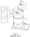
- FIG. 1 illustrates a molten metal feed apparatus disclosed in U.S. Patent No. 7,021,361 .
- the feed apparatus is used to feed molten metal to a die casting machine 11, and includes a ladle 12 for holding molten metal, and a conveyor system 13 for conveying the ladle 12 to a feed position of the die casting machine 11 and for tilting the ladle 12 to pour the molten metal into the die casting machine 11. Since an open space design of the feed apparatus does not favor preservation of the temperature of the molten metal, constant heating is required, which leads to high energy consumption. Furthermore, the temperature of the molten metal drops considerably and the molten metal may oxidize while the molten metal is being conveyed, which may result in defects during the die casting operation that can reduce the production yield.
- FIGS. 2 and 3 illustrate an aluminum-based material melting apparatus disclosed in U.S. Patent Application Publication No. 2014/0054832 .
- the apparatus includes a furnace unit 2 and a feed unit 3.
- the furnace unit 2 includes a closed furnace 21 in spatial communication with the feed unit 3.
- the feed unit 3 includes a feed hopper 31 for receiving particulate aluminum-based raw material, a pre-heating funnel 32, a valve mechanism 33 provided between the feed hopper 31 and the pre-heating funnel 32, and a conveying unit 34.
- the valve mechanism 33 changes to an open state, thereby permitting passage of the raw material into the pre-heating funnel 32.
- the raw material is conveyed from the pre-heating funnel 32 to the closed furnace 21 via the conveying unit 34, and is heated for melting in the closed furnace 21.
- the melting apparatus requires pre-processing of the raw material into particulate form.
- the design of the valve mechanism 33 may lead to a large amount of the raw material being fed at once, which may reduce and does not favor preservation of the temperature of the melting operation. Frequent reheating may be needed, which increases energy consumption.
- US 5 643 528 A and US 2002/0062940 A1 are describing an apparatus for feeding ingots to a melting furnace.
- Object of the invention is to provide an apparatus for feeding raw material bars to a melting furnace according to independent claim 1.
- An apparatus according to the disclosure is for feeding raw material bars to a furnace body of a melting furnace and includes:
- the push mechanism is operable to push the raw material bar in the feed passage downwardly, and the material retarder is configured to retard downward movement of the raw material bar out of the feed passage and into the furnace body.
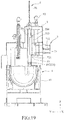
- the embodiment of an apparatus according to the disclosure is adapted for feeding raw material bars 40 to a melting furnace 4.
- the melting furnace 4 includes a heating device 41 and a ladle device 42.
- the heating device 41 is for heating molten metal material and includes a furnace body 411 for containing the molten metal material, heating bars 412, and a partition plate 413 disposed in the furnace body 411.
- the raw material bars 40 are made of aluminum alloy in this embodiment, but may be made of other metal materials such as magnesium alloy. Since the feature of the disclosure does not reside in the specific configuration of the melting furnace 4, which may be readily appreciated by those skilled in the art, further details of the same will not be provided herein for the sake of brevity.
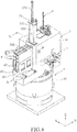
- the apparatus of this embodiment includes an enclosure body 5, a carriage 6, a transferring unit 7, and a feeding unit 8.
- Z-direction is defined as the direction in which the height of the enclosure body 5 extends, and X-direction and Y-direction are mutually orthogonal directions that are also orthogonal to the Z-direction.
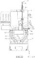
- the enclosure body 5 is disposed above the heating device 41 and includes a housing 51, a plurality of partition plates 52 disposed in the housing 51, a gate mechanism 53, and a pair of parallel guide shafts 54 that are disposed on the housing 51, that extend horizontally in the Y-direction and that are spaced apart from each other in the X-direction.
- the partition plates 52 partition an interior of the housing 51 into a vertically extending feed passage 501 (see Figure 18 ) that is to be disposed above an open top side of the furnace body 411 and that is for spatial communication with the furnace body 411, an access passage 502 that is for spatial communication with an exterior of the housing 51, a bar guiding space 503 that is in spatial communication with the feed passage 501 and the access passage 502, and a vent passage 505 that is for spatial communication with the furnace body 411.
- At least one of the partition plates 52 is formed with vent holes 504 in spatial communication with the access passage 502 and the vent passage 505.
- a bar delivery hole 506 (see Figure 18 ) is formed in one of the partition plates 52 at a junction of the bar guiding space 503 and the feed passage 501 and is configured to permit passage of a vertically oriented raw material bar 40 from the bar guiding space 503 to the feed passage 501.
- the gate mechanism 53 includes a support 531 disposed on the housing 51, a gate member 532 disposed movably at the support 531 and slidable on the support 531 along the Z-direction, and a pressure cylinder 533 for driving opening and closing movement of the gate member 532.
- the pressure cylinder 533 is a pneumatic cylinder, but the present disclosure is not limited in this respect.
- the carriage 6 of this embodiment includes a movable base 61 and two raw material bar holders 62.
- the movable base 61 is slidably disposed on the guide shafts 54, which are disposed outside and adjacent to the access passage 502.
- the movable base 61 has two slide grooves 611, each of which has one of the raw material bar holders 62 movably disposed thereat.
- the movable base 61 is movable on the guide shafts 54 along the Y-direction to align a selected one of the slide grooves 611 with the access passage 502 and permit movement of one of the raw material bar holders 62 along the X-direction into and out of the access passage 502.
- the movable base 61 may be manually moved on the guide shafts 54 but the present disclosure is not limited in this respect.
- only one of the raw material bar holders 62 may enter the access passage 502 at any time, and the other raw material bar holder 62 is in a standby state outside the enclosure body 5.
- the raw material bar holders 62 may be manually moved into and out of the access passage 502 but the present disclosure is not limited in this respect.
- Each raw material bar holder 62 includes a casing body 621, a barrier plate 622, and a plurality of rollers 623 mounted rotatably to the casing body 621 for moving the raw material bar holder 62 into and out of the access passage 502.
- the rollers 623 extend in the Y-direction and are spaced apart from each other in the X-direction.
- the casing body 621 has an opposing pair of casing walls, and a lower part of the casing walls is formed with a pair of bar passage slots 6211 that extend horizontally in the X-direction and that are registered with each other in the Y-direction.
- the casing body 621 has one side formed with a bar entrance opening 6212.
- the barrier plate 622 is connected removably to the casing body 621 for covering and uncovering the bar entrance opening 6212, and cooperates with the casing body 621 to confine a receiving space 624 for receiving the raw material bars 40.
- Each raw material bar holder 62 is configured to hold the raw material bars 40 in a manner that the raw material bars 40 extend horizontally and are disposed in a stack along the Z-direction inside the receiving space 624.
- the raw material bars 40 may be manually supplied to the receiving space 624 but the present disclosure is not limited in this respect.
- the bar passage slots 6211 permit removal of a lowermost one of the raw material bars 40 in the stack from the raw material bar holder 62 by the transferring unit 7.
- the transferring unit 7 is disposed at the enclosure body 5 and includes a bar moving sub-unit 71, an orientation converting sub-unit 72, and a bar delivering sub-unit 73.
- the bar moving sub-unit 71 includes a bar moving member 711 and a first drive member 712 coupled to the bar moving member 711 and operable to drive back and forth movement of the bar moving member 711 in the Y-direction relative to the raw material bar holder 62 inside the access passage 502.
- the orientation converting sub-unit 72 includes a rotatable bar guiding member 721 and a second drive member 722 coupled to and configured to drive bidirectional rotation of the bar guiding member 721 about the Y-direction.
- the bar delivering sub-unit 73 includes a bar advancing member 731 and a third drive member 732 coupled to the bar advancing member 731 and operable to drive back and forth movement of the bar advancing member 731 in the Y-direction relative to the feed passage 501.
- the bar guiding member 721 has one end distal from the second drive member 722 and provided with a stop portion 7211. While the first drive member 712 and the third drive member 732 are exemplified using pneumatic cylinders in this embodiment, and the second drive member 722 is exemplified using a motor in this embodiment, the present disclosure is not limited in this respect.
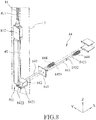
- the feeding unit 8 is disposed at the enclosure body 5 and includes a push mechanism 81 that extends vertically into an upper part of the feed passage 501, and a material retarder 84 that extends into a lower part of the feed passage 501.
- the push mechanism 81 includes a vertically extending screw rod segment 811 and a push block segment 812 coupled to a bottom end of the screw rod segment 811 and disposed in the feed passage 501. As shown in Figure 5 , the push mechanism 81 further includes an actuator 82 and a transmission belt 83. In this embodiment, the actuator 82 is a servo motor, but the present disclosure is not limited in this respect.
- the transmission belt 83 is trained between the screw rod segment 811 and the actuator 82. The actuator 82 is configured to drive rotation of the screw rod segment 811 via the transmission belt 83 for moving the push block segment 812 up and down in the Z-direction, thereby controlling downward moving speed of the raw material bar 40 in the feed passage 501.
- the material retarder 84 includes a limit cage 841 disposed at the enclosure body 5, a blocker 842, a pair of fixing shafts 843, and a pair of biasing components 844.
- the blocker 842 has an inclined face 8421 and a resisting part 8422 at a lower edge of the inclined face 8421.
- the inclined face 8421 and the resisting part 8422 are disposed in the feed passage 501 for contacting the raw material bar 40 in the feed passage 501.
- each fixing shaft 843 extends in the X-direction, and has a front end connected to one side of the blocker 842 opposite to the inclined face 8421, a slide section 8431 extending slidably into the limit cage 841 and slidable along the X-direction, a limit section 8432 to abut against the limit cage 841, and a sleeve section 8433 disposed rearwardly of the limit section 8432 for sleeving of a respective one of the biasing components 844 and extending slidably through the limit cage 841.
- each biasing component 844 is a compression spring that stores a restoring force when compressed, and has opposite ends respectively abutting against the limit cage 841 and the limit section 8432 on the respective fixing shaft 843.
- the biasing components 844 bias the fixing shafts 843 for moving the blocker 842 to project into the feed passage 501.
- the material retarder 84 is configured to retard downward movement of the raw material bar 40 out of the feed passage 501 and into the furnace body 411, and is designed to prevent free fall of the raw material bar 40 in the feed passage 501.
- the raw material bar 40 in the feed passage 501 is pushed downward by the push mechanism 81, the raw material bar 40 applies a downward pushing force on the inclined face 8421 of the blocker 842.
- the blocker 842 moves rearward in the X-direction and the raw material bar 40 moves downward in the Z-direction inside the feed passage 501.
- the blocker 842 continues to contact the raw material bar 40, and friction is generated as a result of contact between the raw material bar 40 and the resisting part 8422 of the blocker 842, thereby arresting free fall of the raw material bar 40 out of the feed passage 501 and into the furnace body 411.
- the raw material bars 40 are stacked in the Z-direction inside the casing body 621 of one of the raw material bar holders 62 via the bar entrance opening 6212.
- the barrier plate 622 is then used to cover the bar entrance opening 6212 for preventing the raw material bars 40 from falling out of the casing body 621.
- the pressure cylinder 533 of the gate mechanism 53 is activated, such as with the use of a computerized control system (not shown), to move the gate member 532 upward in the Z-direction so that access to the access passage 502 is permitted.
- the raw material bar holder 62 filled with the raw material bars 40 is then moved along the corresponding slide groove 611 of the movable base 61 in the X-direction to enter the access passage 502.
- the pressure cylinder 533 is activated, such as via the computerized control system, to move the gate member 532 downward in the Z-direction, thereby closing the access passage 502 to result in a sealed state of the enclosure body 5 and to prevent entry of contaminants and/or ambient cold air. Accordingly, stability of an internal environment of the enclosure body 5 may be ensured.
- the heating device 41 of the melting furnace 4 is also enabled for proceeding with a heating operation.
- the heating bars 412 are activated to heat metal raw material in the furnace body 411.
- the furnace body 411 normally contains an amount of molten liquid for scooping by the ladle device 42.
- the partition plate 413 is disposed adjacent to the feed passage 501, and is used to separate a to-be-melted raw material bar 40 from the ladle device 42.
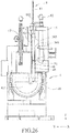
- High temperature gas is produced when the furnace body 411 is in a heated state, and flows into the access passage 502 via the vent passage 505 and the vent holes 504, thereby preheating the raw material bars 40 stored in the raw material bar holder 62 inside the access passage 502.
- the high temperature gas also flows into the access passage 502 via the feed passage 501, the bar delivery hole 506 and the bar guiding space 503, thereby preheating the raw material bar 40 in the feed passage 501 or the bar guiding space 503.
- the raw material bar holder 62 is disposed in the enclosure body 5 after the pre-feeding operation.
- the transferring unit 7 is configured to transfer the raw material bars 40 held by the raw material bar holder 62 in the access passage 502 one at a time to the feed passage 501 in a manner that the raw material bar 40 extends vertically in the feed passage 501 with the push mechanism 81 being disposed above the raw material bar 40 and with the raw material bar 40 contacting the material retainer 84.
- the bar moving sub-unit 71 is configured to move the raw material bars 40 held by the raw material bar holder 62 in the access passage 502 one at a time to the orientation converting sub-unit 72.
- the first drive member 712 of the bar moving sub-unit 71 is controlled, such as via the computerized control system (not shown), to drive the bar moving member 711 of the bar moving sub-unit 71 for moving a lowermost one of the raw material bars 40 in the casing body 621 of the raw material bar holder 62 out of the latter through the bar passage slots 6211 (see Figure 7 ) and onto the orientation converting sub-unit 72.
- the force applied by the bar moving member 711 for moving the lowermost raw material bar 40 may be a constant force.
- the orientation converting sub-unit 72 is configured to convert the raw material bar 40 received from the bar moving sub-unit 71 from a horizontal orientation to a vertical orientation inside the bar guiding space 503 of the housing 51 of the enclosure body 5.
- the bar guiding member 721 of the orientation converting sub-unit 72 receives the raw material bar 40 with the horizontal orientation from the bar moving sub-unit 71.
- the second drive member 722 (see Figure 5 ) of the orientation converting sub-unit 72 is controlled, such as via the computerized control system (not shown), to drive rotation of the bar guiding member 721 for converting the raw material bar 40 from the horizontal orientation to the vertical orientation inside the bar guiding space 503.
- the stop portion 7211 of the bar guiding member 721 is used to keep the raw material bar 40 from sliding while the latter is being converted to the vertical orientation.
- the bar delivering sub-unit 73 is configured to transfer the raw material bar 40 converted by the orientation converting sub-unit 72 to the feed passage 501.
- the third drive member 732 of the bar delivering sub-unit 73 is controlled, such as via the computerized control system (not shown), to drive movement of the bar advancing member 731 for transferring the vertically oriented raw material bar 40 from the bar guiding space 503 to the feed passage 501 through the bar delivery hole 506.
- the bar delivery hole 506 is disposed below the push mechanism 81 and above the material retarder 84.
- one cycle of operation of each of the bar moving sub-unit 71, the orientation converting sub-unit 72 and the bar delivering sub-unit 73 transfers one raw material bar 40 from the raw material bar holder 62 in the access passage 502 to the feed passage 501.
- operation of the orientation converting sub-unit 72 starts after operation of the bar moving sub-unit 71 is completed
- operation of the bar delivering sub-unit 73 starts after operation of the orientation converting sub-unit 72 is completed.
- the raw material bar 40 drops onto the blocker 842 of the material retarder 84 of the feeding unit 8 when transferred to the feed passage 501, and is thus restricted by the blocker 842 from falling directly into the furnace body 411.
- the actuator 82 of the push mechanism 81 is controlled, such as through the computerized control system (not shown), to drive rotation of the screw rod segment 811 via the transmission belt 83 for moving the push block segment 812 downward in the Z-direction inside the feed passage 501 and pushing the raw material bar 40 in the feed passage 501 downwardly via the push block segment 812.
- the raw material bar 40 applies a downward pushing force on the inclined face 8421 of the blocker 842, the blocker 842 moves rearward in the X-direction, and the raw material bar 40 moves downward in the Z-direction inside the feed passage 501.
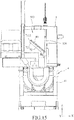
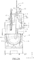
- the raw material bar 40 is thus moved gradually into the furnace body 411 to extend to the level of the molten material (indicated by phantom lines in Figure 23 ) in the furnace body 411.
- the actuator 82 is controlled, such as via the computerized control system (not shown), to drive upward movement of the push block segment 812 in the Z-direction via the transmission belt 83 and the screw rod segment 811.
- a second raw material bar 40 is transferred to the feed passage 501 by the transferring unit 7.
- the actuator 82 is controlled, such as via the computerized control system (not shown), to drive downward movement of the push block segment 812 in the Z-direction via the transmission belt 83 and the screw rod segment 811, thereby pushing the second raw material bar 40 to move downward in the feed passage 501.
- the first raw material bar 40 is then pushed by the second raw material bar 40 to continue to move downward out of the feed passage 501 and into the furnace body 411.
- the raw material bar 40 As the raw material bar 40 gradually extends into the molten material in the furnace body 411, the raw material bar 40 will be heated and begins to melt. Therefore, a large drop in the temperature of the molten material can be avoided due to the gradual extension of the raw material bar 40 into the furnace body 411.
- transfer operation of a next raw material bar 40 by the transferring unit 7 can continue to ensure continuous and stable feeding of the raw material bars 40 into the furnace body 411. This may help prevent large fluctuations in the temperature of the molten material in the furnace body 411, and may reduce the need to frequently activate the heating bars 412 so as to reduce energy consumption.
- the ladle device 42 may be operated for feeding the molten material to a die casting machine (not shown) .
- the other raw material bar holder 62 is standing by outside the housing 51 of the enclosure body 5 and may be filled with the raw material bars 40.
- the emptied raw material bar holder 62 may be moved back to the movable base 61.
- the movable base 61 may then be moved so that the filled raw material bar holder 62 may be moved into the access passage 502 of the housing 51 of the enclosure body 5 to continue supplying the raw material bars 40 to the feed passage 501.
Landscapes
- Engineering & Computer Science (AREA)
- Mechanical Engineering (AREA)
- General Engineering & Computer Science (AREA)
- Vertical, Hearth, Or Arc Furnaces (AREA)
- Furnace Charging Or Discharging (AREA)
- Crucibles And Fluidized-Bed Furnaces (AREA)
- Furnace Details (AREA)
Claims (18)
- Appareil d'alimentation de barres de matière première (40) vers un corps de four (411) d'un four de fusion (4), ledit appareil étant caractérisé par:un corps d'enceinte (5) pourvu d'un passage d'alimentation (501) qui s'étend verticalement et qui doit être disposé au-dessus d'un côté supérieur ouvert du corps de four (411);une unité d'alimentation (8) comportant un mécanisme de poussée (81) qui s'étend verticalement dans une partie supérieure du passage d'alimentation (501), et un retardateur de matériau (84) qui s'étend dans une partie inférieure du passage d'alimentation (501); etune unité de transfert (7) disposée sur le corps d'enceinte (5) et configurée pour transférer une barre de matière première (40) vers le passage d'alimentation (501) de sorte que la barre de matière première (40) s'étende verticalement dans le passage d'alimentation (501), le mécanisme de poussée (81) étant disposé au-dessus de la barre de matière première (40) et la barre de matière première (40) étant en contact avec le retardateur de matériau (84);le mécanisme de poussée (81) pouvant être actionné pour pousser la barre de matière première (40) dans le passage d'alimentation (501) vers le bas et le retardateur de matériau (84) étant configuré pour retarder le mouvement de descente de la barre de matière première (40) hors du passage d'alimentation (501) et vers le corps de four (411);le corps d'enceinte (5) présentant par ailleurs un passage d'accès (502);l'appareil comprenant par ailleurs un chariot (6) qui est déplaçable vers le et hors du passage d'accès (502) et qui est configuré pour maintenir les barres de matière première (40);le corps d'enceinte (5) présentant par ailleurs un mécanisme de porte (53) qui est configuré pour ouvrir et fermer sélectivement le passage d'accès (502);le corps d'enceinte (5) étant formé avec au moins un trou d'aération (504) qui permet que le gaz à haute température provenant du corps de four (411) s'écoule vers le corps d'enceinte (5) pour préchauffer les barres de matière première (40) dans le corps d'enceinte (5); etle retardateur de matériau (84) comportant:un bloqueur (842) qui présente une face inclinée (8421) et une partie résistante (8422) sur un bord inférieur de la face inclinée (8421), la face inclinée (8421) et la partie résistante (8422) étant disposées dans le passage d'alimentation (501) pour entrer en contact avec la barre de matière première (40) dans le passage d'alimentation (501),une cage de limitation (841) qui est disposée sur le corps d'enceinte (5),une paire d'arbres de fixation (843) présentant, chacun, une extrémité connectée au bloqueur (842) et s'étendant, chacun, de manière coulissante à travers la cage de limitation (841), etune paire d'éléments de sollicitation (844) emmanchés, chacun, sur l'un respectif des arbres de fixation (843) et présentant, chacun, des extrémités opposées venant respectivement en butée contre la cage de limitation (841) et l'un respectif des arbres de fixation (843), les éléments de sollicitation (844) sollicitant les arbres de fixation (843) pour déplacer le bloqueur (842) de sorte qu'il pénètre dans le passage d'alimentation (501).
- Appareil selon la revendication 1, caractérisé par ailleurs par le fait que le mécanisme de porte (53) comporte un support (531), un élément de porte (532) disposé de manière mobile sur le support (531) et un cylindre de pression (533) destiné à commander l'ouverture et la fermeture de l'élément de porte (532).
- Appareil selon la revendication 1, caractérisé par ailleurs par le fait que l'unité de transfert (7) est configurée pour transférer les barres de matière première (40) maintenues par le chariot (6) dans le passage d'accès (502) une à une vers le passage d'alimentation (501).
- Appareil selon la revendication 3, caractérisé par ailleurs par le fait que:le chariot (6) est configuré pour maintenir les barres de matière première (40) de sorte que les barres de matière première (40) s'étendent horizontalement et soient disposées en pile; etl'unité de transfert (7) comporte une sous-unité de déplacement de barre (71), une sous-unité de conversion d'orientation (72) et une sous-unité de délivrance de barre (73);la sous-unité de déplacement de barre (71) étant configurée pour déplacer les barres de matière première (40) maintenues par le chariot (6) dans le passage d'accès (502) une à une vers la sous-unité de conversion d'orientation (72);la sous-unité de conversion d'orientation (72) étant configurée pour convertir la barre de matière première (40) reçue de la sous-unité de déplacement de barre (71) d'une orientation horizontale à une orientation verticale à l'intérieur du corps d'enceinte (5);la sous-unité de délivrance de barre (73) étant configurée pour transférer la barre de matière première (40) convertie par la sous-unité de conversion d'orientation (72) vers le passage d'alimentation (501).
- Appareil selon la revendication 4, caractérisé par ailleurs par le fait que la sous-unité de conversion d'orientation (72) comporte un élément de guidage de barre rotatif (721) disposé de manière à recevoir la barre de matière première (40) avec l'orientation horizontale de la sous-unité de déplacement de barre (71), et un élément d'entraînement (722) couplé à et configuré pour entraîner l'élément de guidage de barre (721) en rotation pour convertir la barre de matière première (40) reçue de la sous-unité de déplacement de barre (71) de l'orientation horizontale à l'orientation verticale à l'intérieur du corps d'enceinte (5).
- Appareil selon la revendication 5, caractérisé par ailleurs par le fait que l'élément d'entraînement (722) est un moteur.
- Appareil selon la revendication 4, caractérisé par ailleurs par le fait que la sous-unité de déplacement de barre (71) comporte un élément de déplacement de barre (711) configuré pour déplacer les barres de matière première (40) maintenues par le chariot (6) à l'intérieur du passage d'accès (502) une à une vers la sous-unité de conversion d'orientation (72), et un élément d'entraînement (712) couplé à l'élément de déplacement de barre (711) et actionnable pour commander le mouvement de va-et-vient de à l'élément de déplacement de barre (711) par rapport au chariot (6) à l'intérieur du passage d'accès (502).
- Appareil selon la revendication 7, caractérisé par ailleurs par le fait que l'élément d'entraînement (712) est un cylindre de pression.
- Appareil selon la revendication 4, caractérisé par ailleurs par le fait que la sous-unité de délivrance de barre (73) comporte un élément d'avance de barre (731) configuré pour transférer la barre de matière première (40) convertie à l'orientation verticale par la sous-unité de conversion d'orientation (72) vers le passage d'alimentation (501), et un élément d'entraînement (732) couplé à l'élément d'avance de barre (731) et actionnable pour commander le mouvement de va-et-vient de l'élément d'avance (731) par rapport au passage d'alimentation (501).
- Appareil selon la revendication 9, caractérisé par ailleurs par le fait que l'élément d'entraînement (732) est un cylindre de pression.
- Appareil selon la revendication 1, caractérisé par ailleurs par le fait que le chariot (6) comporte au moins un support de barres de matière première (62) qui est configuré pour maintenir les barres de matière première (40) de sorte que les barres de matière première (40) s'étendent horizontalement et soient disposées en pile, le support de barres de matière première (62) comportant un corps de boîtier (621) et une pluralité de rouleaux (623) montés de manière rotative sur le corps de boîtier (621) pour déplacer le support de barres de matière première (62) vers et hors du passage d'accès (502), le corps de boîtier (621) présentant une paire opposée de parois de boîtier, une partie inférieure des parois de boîtier étant formée avec une paire alignée de fentes de passage de barre (6211) qui s'étendent horizontalement, les fentes de passage de barre (6211) permettant l'enlèvement de l'une la plus basse des barres de matière première (40) dans la pile du support de barres de matière première (62) par l'unité de transfert (7).
- Appareil selon la revendication 11, caractérisé par ailleurs par le fait que le corps de boîtier (621) présente un côté formé avec une ouverture d'entrée de barre (6212), le support de barres de matière première (62) comportant par ailleurs une plaque barrière (622) connectée de manière amovible au corps de boîtier (621) pour couvrir et découvrir l'ouverture d'entrée de barre (6212), la plaque barrière (622) coopérant avec le corps de boîtier (621) pour délimiter un espace de réception (624) pour recevoir les barres de matière première (40).
- Appareil selon la revendication 11, caractérisé par ailleurs par le fait que le corps d'enceinte (5) comporte des arbres de guidage parallèles (54) qui s'étendent horizontalement et sont disposés à l'extérieur de et adjacents au passage d'accès (502), le chariot (6) comportant une base mobile (61) disposée de manière mobile sur les arbres de guidage (54) et deux des supports de barres de matière première (62), la base mobile (61) présentant deux rainures de coulissement (611) présentant, chacune, l'un des supports de barres de matière première (62) y disposé de manière déplaçable, la base mobile (61) étant déplaçable sur les arbres de guidage (54) pour aligner l'une sélectionnée des rainures de coulissement (611) avec le passage d'accès (502) et permettre le déplacement de l'un des supports de barres de matière première (62) vers le et hors du passage d'accès (502).
- Appareil selon la revendication 1, caractérisé par le fait que le mécanisme de poussée (81) comporte:un segment de tige de vis s'étendant verticalement (811);un segment de bloc de poussée (812) couplé au segment de tige de vis (811) et disposé dans le passage d'alimentation (501);un actionneur (82); etune courroie de transmission (83) entraînée entre le segment de tige de vis (811) et l'actionneur (82);l'actionneur (82) étant configuré pour entraîner le segment de tige de vis (811) en rotation par l'intermédiaire de la courroie de transmission (83) pour déplacer le segment de bloc de poussée (812) vers le bas dans le passage d'alimentation (501) et pour pousser la barre de matière première (40) dans le passage d'alimentation (501) vers le bas par l'intermédiaire du segment de bloc de poussée (812).
- Appareil selon la revendication 14, caractérisé par ailleurs par le fait que l'actionneur (82) est un servomoteur.
- Appareil selon la revendication 1, caractérisé par le fait que le corps d'enceinte (5) comporte un boîtier (51) et une pluralité de plaques de cloisonnement (52) disposées dans le boîtier (51), les plaques de cloisonnement (52) divisant l'intérieur du boîtier (51) en un passage d'alimentation (501) qui est destiné à la communication spatiale avec le corps de four (411), un passage d'accès (502) qui est destiné à la communication spatiale avec l'extérieur du boîtier (51), un espace de guidage de barre (503) qui est en communication spatiale avec le passage d'alimentation (501) et le passage d'accès (502), et un passage d'aération (505) qui est destiné à la communication spatiale avec le corps de four (411), au moins l'une des plaques de cloisonnement (52) étant formée avec des trous d'aération (504) en communication spatiale avec le passage d'accès (502) et le passage d'aération (505), le passage d'aération (505) et les trous d'aération (504) permettant que le gaz à haute température provenant du corps de four (411) s'écoule vers le corps d'enceinte (5) pour préchauffer la barre de matière première (40) dans le corps d'enceinte (5).
- Appareil selon la revendication 16, caractérisé par ailleurs par le fait que l'une des plaques de cloisonnement (52) est formée avec un trou de délivrance de barre (506) à une jonction entre l'espace de guidage de barre (503) et le passage d'alimentation (501), disposé au-dessous du mécanisme de poussée (81) et au-dessus du retardateur de matériau (84), et configuré pour permettre le passage de la barre de matière première (40) de l'espace de guidage de barre (503) vers le passage d'alimentation (501).
- Appareil selon la revendication 1, caractérisé par le fait que l'unité de transfert (7) est configurée pour convertir la barre de matière première (40) d'une orientation horizontale à une orientation verticale avant de transférer la barre de matière première (40) vers le passage d'alimentation (501).
Applications Claiming Priority (1)
| Application Number | Priority Date | Filing Date | Title |
|---|---|---|---|
| TW104116673A TWI583459B (zh) | 2015-05-25 | 2015-05-25 | Furnace material for long melting furnace |
Publications (2)
| Publication Number | Publication Date |
|---|---|
| EP3098552A1 EP3098552A1 (fr) | 2016-11-30 |
| EP3098552B1 true EP3098552B1 (fr) | 2018-08-29 |
Family
ID=54542105
Family Applications (1)
| Application Number | Title | Priority Date | Filing Date |
|---|---|---|---|
| EP15194515.1A Active EP3098552B1 (fr) | 2015-05-25 | 2015-11-13 | Appareil de barres de matière première d'alimentation pour un four de fusion |
Country Status (6)
| Country | Link |
|---|---|
| US (1) | US10119763B2 (fr) |
| EP (1) | EP3098552B1 (fr) |
| JP (1) | JP6153987B2 (fr) |
| KR (1) | KR101748819B1 (fr) |
| CN (1) | CN106270451B (fr) |
| TW (1) | TWI583459B (fr) |
Families Citing this family (5)
| Publication number | Priority date | Publication date | Assignee | Title |
|---|---|---|---|---|
| CN113465370B (zh) * | 2021-07-07 | 2023-02-24 | 江西耐乐科技协同创新有限公司 | 一种废铜精炼装置 |
| CN113714459B (zh) * | 2021-09-22 | 2024-03-26 | 河南中孚技术中心有限公司 | 一种用于铝棒加工回炉煅烧用的投料装置及施工方法 |
| US20240409447A1 (en) * | 2023-06-12 | 2024-12-12 | Owens-Brockway Glass Container Inc. | Glass batch inlet and cleaning device |
| JP7805383B2 (ja) * | 2024-02-06 | 2026-01-23 | リョービ株式会社 | 材料投入装置、材料投入システム |
| CN121677361B (zh) * | 2026-02-04 | 2026-04-10 | 中国机械总院集团沈阳铸造研究所有限公司 | 一种真空感应熔炼方法、装置及熔炼炉 |
Family Cites Families (27)
| Publication number | Priority date | Publication date | Assignee | Title |
|---|---|---|---|---|
| US3836325A (en) * | 1973-12-11 | 1974-09-17 | Nippon Steel Corp | Apparatus for charging materials into vertical heating furnace |
| JPS6130768Y2 (fr) * | 1977-05-19 | 1986-09-08 | ||
| DE2856617C2 (de) * | 1978-12-29 | 1980-09-18 | Werner & Pfleiderer, 7000 Stuttgart | Beschickungsvorrichtung für einen unter Druck stehenden Behälter |
| FR2539861B1 (fr) * | 1983-01-20 | 1987-08-07 | Ferco Int Usine Ferrures | Dispositif d'alimentation automatique du creuset d'une machine a couler sous pression en chambre chaude |
| JPS60226694A (ja) * | 1984-04-20 | 1985-11-11 | デイナモルド、インタ−ナシヨナル | 金属インゴツトの溶解装置 |
| US4581063A (en) * | 1984-05-03 | 1986-04-08 | Sumitomo Light Metal Industries Ltd. | Method and apparatus for melting metal ingots |
| US5226774A (en) * | 1991-01-28 | 1993-07-13 | Cadence Chemical Resources, Inc. | Device for charging combustible solids to rotary kilns |
| JP3628040B2 (ja) * | 1993-06-25 | 2005-03-09 | 株式会社トウネツ | 金属溶湯保持炉 |
| JPH08294765A (ja) * | 1995-04-26 | 1996-11-12 | Toshiba Mach Co Ltd | 定湯面溶解保持炉 |
| US5643528A (en) * | 1995-06-06 | 1997-07-01 | Musket System Design And Control Inc. | Controlled magnesium melt process, system and components therefor |
| JPH09155526A (ja) * | 1995-12-01 | 1997-06-17 | Japan Steel Works Ltd:The | 金属材料の射出装置 |
| JP3452812B2 (ja) * | 1998-10-27 | 2003-10-06 | 東芝機械株式会社 | インゴット供給装置およびインゴット供給方法 |
| US6336809B1 (en) * | 1998-12-15 | 2002-01-08 | Consolidated Engineering Company, Inc. | Combination conduction/convection furnace |
| JP4421074B2 (ja) | 2000-04-26 | 2010-02-24 | 株式会社メッツ | 金属の溶解設備 |
| JP3766269B2 (ja) * | 2000-11-29 | 2006-04-12 | 東芝機械株式会社 | インゴット供給装置およびインゴット供給方法 |
| CN2459794Y (zh) * | 2000-12-05 | 2001-11-14 | 兴豪生精密工业股份有限公司 | 电池连接器自动组装机 |
| JP2002224812A (ja) | 2001-01-29 | 2002-08-13 | Ube Machinery Corporation Ltd | 金属溶解装置及び金属溶解方法 |
| JP3993813B2 (ja) * | 2002-10-31 | 2007-10-17 | 有限会社リムテック | 溶融金属材料の射出装置 |
| TWI280166B (en) | 2002-12-26 | 2007-05-01 | Toshiba Machine Co Ltd | Liquid material feed apparatus of die casting machine, liquid material feed method, and ladle |
| CN2652563Y (zh) * | 2003-08-29 | 2004-11-03 | 常桂英 | 锌合金熔液提送装置 |
| JP2006064304A (ja) * | 2004-08-27 | 2006-03-09 | Aisin Seiki Co Ltd | 金属塊材装入装置 |
| JP2008196807A (ja) * | 2007-02-14 | 2008-08-28 | Kenzo Takahashi | 溶解炉用原料押込装置及びそれを組み込んだ溶解炉システム |
| DE102007015964A1 (de) * | 2007-04-03 | 2008-10-09 | Sms Demag Ag | Vorrichtung zum Einbringen metallischer Barren in ein Metallbad |
| TW201408398A (zh) | 2012-08-23 | 2014-03-01 | 游家龍 | 供應鋁合金熔融液的方法及裝置 |
| TWM444231U (zh) * | 2012-08-23 | 2013-01-01 | jia-long You | 供應鋁合金熔融液的裝置 |
| CN204115476U (zh) * | 2014-07-04 | 2015-01-21 | 江西亚菲达铜业有限公司 | 一种熔铜炉 |
| TWM509334U (zh) * | 2015-05-25 | 2015-09-21 | jia-long You | 熔融爐之長條型料材供應裝置 |
-
2015
- 2015-05-25 TW TW104116673A patent/TWI583459B/zh active
- 2015-07-07 CN CN201510393303.9A patent/CN106270451B/zh active Active
- 2015-11-05 US US14/933,519 patent/US10119763B2/en active Active
- 2015-11-06 JP JP2015218379A patent/JP6153987B2/ja active Active
- 2015-11-13 EP EP15194515.1A patent/EP3098552B1/fr active Active
- 2015-11-18 KR KR1020150161866A patent/KR101748819B1/ko not_active Expired - Fee Related
Also Published As
| Publication number | Publication date |
|---|---|
| JP6153987B2 (ja) | 2017-06-28 |
| EP3098552A1 (fr) | 2016-11-30 |
| KR101748819B1 (ko) | 2017-07-03 |
| TW201641184A (zh) | 2016-12-01 |
| US10119763B2 (en) | 2018-11-06 |
| CN106270451B (zh) | 2018-08-21 |
| JP2016217692A (ja) | 2016-12-22 |
| US20160348972A1 (en) | 2016-12-01 |
| KR20160138337A (ko) | 2016-12-05 |
| CN106270451A (zh) | 2017-01-04 |
| TWI583459B (zh) | 2017-05-21 |
Similar Documents
| Publication | Publication Date | Title |
|---|---|---|
| EP3098552B1 (fr) | Appareil de barres de matière première d'alimentation pour un four de fusion | |
| US8051755B2 (en) | Bar feeder, feed rod vibration prevention support of material feeder and vibration stopper of material feeder | |
| CN105881912A (zh) | 一种3d打印自动切换料装置 | |
| KR20170086014A (ko) | 압출 프레스의 빌렛 반송 장치 | |
| EP3020933A1 (fr) | Procédé et dispositif pour alimenter en sodium métallique des vannes creuses | |
| CN113601864A (zh) | 一种眼镜自动插针设备 | |
| KR101764182B1 (ko) | 자동 잉곳 투입장치 | |
| CN102189232B (zh) | 用于保持和替换浇铸板的装置 | |
| CN107285058A (zh) | 一种粉料装埚自动线 | |
| JPH1177231A (ja) | 鍛造プレス機のビレット供給装置 | |
| EP3297784B1 (fr) | Changeur d'électrodes automatisé pour usinage par électroérosion | |
| JP2022548850A (ja) | バー供給装置 | |
| EP3012085A1 (fr) | Machine de moulage à injection | |
| CN214582511U (zh) | 一种方便调节物料间距的间隔上料系统 | |
| US6557619B2 (en) | Ingot supplying apparatus and method | |
| CN206779681U (zh) | 自动化超声波铝丝压焊机 | |
| CN204735705U (zh) | 熔融炉的长条型料材供应装置 | |
| CN209758024U (zh) | 包膜油桶加热设备外置进料装置 | |
| CN208467265U (zh) | 一种粉末冶金制品用烧结炉均匀投料装置 | |
| TWI766693B (zh) | 具有垂直填料裝置的金屬熔融爐 | |
| CN112775411B (zh) | 一种物料配送系统及其配送方法 | |
| KR101672363B1 (ko) | 용접 팁 카트리지 자동 충전 장치 | |
| WO2000003822A1 (fr) | Dispositif et procede servant a reguler l'ecoulement d'un metal en fusion | |
| CN205437965U (zh) | 一种工件的加工设备 | |
| CN109593962B (zh) | 金属回收设备 |
Legal Events
| Date | Code | Title | Description |
|---|---|---|---|
| PUAI | Public reference made under article 153(3) epc to a published international application that has entered the european phase |
Free format text: ORIGINAL CODE: 0009012 |
|
| AK | Designated contracting states |
Kind code of ref document: A1 Designated state(s): AL AT BE BG CH CY CZ DE DK EE ES FI FR GB GR HR HU IE IS IT LI LT LU LV MC MK MT NL NO PL PT RO RS SE SI SK SM TR |
|
| AX | Request for extension of the european patent |
Extension state: BA ME |
|
| 17P | Request for examination filed |
Effective date: 20170523 |
|
| RBV | Designated contracting states (corrected) |
Designated state(s): AL AT BE BG CH CY CZ DE DK EE ES FI FR GB GR HR HU IE IS IT LI LT LU LV MC MK MT NL NO PL PT RO RS SE SI SK SM TR |
|
| GRAP | Despatch of communication of intention to grant a patent |
Free format text: ORIGINAL CODE: EPIDOSNIGR1 |
|
| INTG | Intention to grant announced |
Effective date: 20171129 |
|
| GRAJ | Information related to disapproval of communication of intention to grant by the applicant or resumption of examination proceedings by the epo deleted |
Free format text: ORIGINAL CODE: EPIDOSDIGR1 |
|
| GRAL | Information related to payment of fee for publishing/printing deleted |
Free format text: ORIGINAL CODE: EPIDOSDIGR3 |
|
| GRAS | Grant fee paid |
Free format text: ORIGINAL CODE: EPIDOSNIGR3 |
|
| INTC | Intention to grant announced (deleted) | ||
| GRAR | Information related to intention to grant a patent recorded |
Free format text: ORIGINAL CODE: EPIDOSNIGR71 |
|
| INTG | Intention to grant announced |
Effective date: 20180607 |
|
| GRAA | (expected) grant |
Free format text: ORIGINAL CODE: 0009210 |
|
| AK | Designated contracting states |
Kind code of ref document: B1 Designated state(s): AL AT BE BG CH CY CZ DE DK EE ES FI FR GB GR HR HU IE IS IT LI LT LU LV MC MK MT NL NO PL PT RO RS SE SI SK SM TR |
|
| REG | Reference to a national code |
Ref country code: GB Ref legal event code: FG4D |
|
| REG | Reference to a national code |
Ref country code: CH Ref legal event code: EP |
|
| REG | Reference to a national code |
Ref country code: AT Ref legal event code: REF Ref document number: 1035607 Country of ref document: AT Kind code of ref document: T Effective date: 20180915 |
|
| REG | Reference to a national code |
Ref country code: IE Ref legal event code: FG4D |
|
| REG | Reference to a national code |
Ref country code: DE Ref legal event code: R096 Ref document number: 602015015392 Country of ref document: DE |
|
| REG | Reference to a national code |
Ref country code: NL Ref legal event code: MP Effective date: 20180829 |
|
| REG | Reference to a national code |
Ref country code: LT Ref legal event code: MG4D |
|
| PG25 | Lapsed in a contracting state [announced via postgrant information from national office to epo] |
Ref country code: NO Free format text: LAPSE BECAUSE OF FAILURE TO SUBMIT A TRANSLATION OF THE DESCRIPTION OR TO PAY THE FEE WITHIN THE PRESCRIBED TIME-LIMIT Effective date: 20181129 Ref country code: BG Free format text: LAPSE BECAUSE OF FAILURE TO SUBMIT A TRANSLATION OF THE DESCRIPTION OR TO PAY THE FEE WITHIN THE PRESCRIBED TIME-LIMIT Effective date: 20181129 Ref country code: NL Free format text: LAPSE BECAUSE OF FAILURE TO SUBMIT A TRANSLATION OF THE DESCRIPTION OR TO PAY THE FEE WITHIN THE PRESCRIBED TIME-LIMIT Effective date: 20180829 Ref country code: SE Free format text: LAPSE BECAUSE OF FAILURE TO SUBMIT A TRANSLATION OF THE DESCRIPTION OR TO PAY THE FEE WITHIN THE PRESCRIBED TIME-LIMIT Effective date: 20180829 Ref country code: LT Free format text: LAPSE BECAUSE OF FAILURE TO SUBMIT A TRANSLATION OF THE DESCRIPTION OR TO PAY THE FEE WITHIN THE PRESCRIBED TIME-LIMIT Effective date: 20180829 Ref country code: FI Free format text: LAPSE BECAUSE OF FAILURE TO SUBMIT A TRANSLATION OF THE DESCRIPTION OR TO PAY THE FEE WITHIN THE PRESCRIBED TIME-LIMIT Effective date: 20180829 Ref country code: IS Free format text: LAPSE BECAUSE OF FAILURE TO SUBMIT A TRANSLATION OF THE DESCRIPTION OR TO PAY THE FEE WITHIN THE PRESCRIBED TIME-LIMIT Effective date: 20181229 Ref country code: RS Free format text: LAPSE BECAUSE OF FAILURE TO SUBMIT A TRANSLATION OF THE DESCRIPTION OR TO PAY THE FEE WITHIN THE PRESCRIBED TIME-LIMIT Effective date: 20180829 |
|
| PG25 | Lapsed in a contracting state [announced via postgrant information from national office to epo] |
Ref country code: HR Free format text: LAPSE BECAUSE OF FAILURE TO SUBMIT A TRANSLATION OF THE DESCRIPTION OR TO PAY THE FEE WITHIN THE PRESCRIBED TIME-LIMIT Effective date: 20180829 Ref country code: AL Free format text: LAPSE BECAUSE OF FAILURE TO SUBMIT A TRANSLATION OF THE DESCRIPTION OR TO PAY THE FEE WITHIN THE PRESCRIBED TIME-LIMIT Effective date: 20180829 Ref country code: LV Free format text: LAPSE BECAUSE OF FAILURE TO SUBMIT A TRANSLATION OF THE DESCRIPTION OR TO PAY THE FEE WITHIN THE PRESCRIBED TIME-LIMIT Effective date: 20180829 |
|
| PG25 | Lapsed in a contracting state [announced via postgrant information from national office to epo] |
Ref country code: RO Free format text: LAPSE BECAUSE OF FAILURE TO SUBMIT A TRANSLATION OF THE DESCRIPTION OR TO PAY THE FEE WITHIN THE PRESCRIBED TIME-LIMIT Effective date: 20180829 Ref country code: EE Free format text: LAPSE BECAUSE OF FAILURE TO SUBMIT A TRANSLATION OF THE DESCRIPTION OR TO PAY THE FEE WITHIN THE PRESCRIBED TIME-LIMIT Effective date: 20180829 Ref country code: IT Free format text: LAPSE BECAUSE OF FAILURE TO SUBMIT A TRANSLATION OF THE DESCRIPTION OR TO PAY THE FEE WITHIN THE PRESCRIBED TIME-LIMIT Effective date: 20180829 Ref country code: ES Free format text: LAPSE BECAUSE OF FAILURE TO SUBMIT A TRANSLATION OF THE DESCRIPTION OR TO PAY THE FEE WITHIN THE PRESCRIBED TIME-LIMIT Effective date: 20180829 Ref country code: CZ Free format text: LAPSE BECAUSE OF FAILURE TO SUBMIT A TRANSLATION OF THE DESCRIPTION OR TO PAY THE FEE WITHIN THE PRESCRIBED TIME-LIMIT Effective date: 20180829 Ref country code: PL Free format text: LAPSE BECAUSE OF FAILURE TO SUBMIT A TRANSLATION OF THE DESCRIPTION OR TO PAY THE FEE WITHIN THE PRESCRIBED TIME-LIMIT Effective date: 20180829 |
|
| PG25 | Lapsed in a contracting state [announced via postgrant information from national office to epo] |
Ref country code: SK Free format text: LAPSE BECAUSE OF FAILURE TO SUBMIT A TRANSLATION OF THE DESCRIPTION OR TO PAY THE FEE WITHIN THE PRESCRIBED TIME-LIMIT Effective date: 20180829 Ref country code: DK Free format text: LAPSE BECAUSE OF FAILURE TO SUBMIT A TRANSLATION OF THE DESCRIPTION OR TO PAY THE FEE WITHIN THE PRESCRIBED TIME-LIMIT Effective date: 20180829 Ref country code: SM Free format text: LAPSE BECAUSE OF FAILURE TO SUBMIT A TRANSLATION OF THE DESCRIPTION OR TO PAY THE FEE WITHIN THE PRESCRIBED TIME-LIMIT Effective date: 20180829 |
|
| REG | Reference to a national code |
Ref country code: DE Ref legal event code: R097 Ref document number: 602015015392 Country of ref document: DE |
|
| REG | Reference to a national code |
Ref country code: CH Ref legal event code: PL |
|
| PLBE | No opposition filed within time limit |
Free format text: ORIGINAL CODE: 0009261 |
|
| STAA | Information on the status of an ep patent application or granted ep patent |
Free format text: STATUS: NO OPPOSITION FILED WITHIN TIME LIMIT |
|
| PG25 | Lapsed in a contracting state [announced via postgrant information from national office to epo] |
Ref country code: LU Free format text: LAPSE BECAUSE OF NON-PAYMENT OF DUE FEES Effective date: 20181113 Ref country code: MC Free format text: LAPSE BECAUSE OF FAILURE TO SUBMIT A TRANSLATION OF THE DESCRIPTION OR TO PAY THE FEE WITHIN THE PRESCRIBED TIME-LIMIT Effective date: 20180829 |
|
| 26N | No opposition filed |
Effective date: 20190531 |
|
| REG | Reference to a national code |
Ref country code: BE Ref legal event code: MM Effective date: 20181130 |
|
| REG | Reference to a national code |
Ref country code: IE Ref legal event code: MM4A |
|
| PG25 | Lapsed in a contracting state [announced via postgrant information from national office to epo] |
Ref country code: LI Free format text: LAPSE BECAUSE OF NON-PAYMENT OF DUE FEES Effective date: 20181130 Ref country code: SI Free format text: LAPSE BECAUSE OF FAILURE TO SUBMIT A TRANSLATION OF THE DESCRIPTION OR TO PAY THE FEE WITHIN THE PRESCRIBED TIME-LIMIT Effective date: 20180829 Ref country code: CH Free format text: LAPSE BECAUSE OF NON-PAYMENT OF DUE FEES Effective date: 20181130 |
|
| PG25 | Lapsed in a contracting state [announced via postgrant information from national office to epo] |
Ref country code: IE Free format text: LAPSE BECAUSE OF NON-PAYMENT OF DUE FEES Effective date: 20181113 Ref country code: FR Free format text: LAPSE BECAUSE OF NON-PAYMENT OF DUE FEES Effective date: 20181130 |
|
| PG25 | Lapsed in a contracting state [announced via postgrant information from national office to epo] |
Ref country code: BE Free format text: LAPSE BECAUSE OF NON-PAYMENT OF DUE FEES Effective date: 20181130 |
|
| PG25 | Lapsed in a contracting state [announced via postgrant information from national office to epo] |
Ref country code: MT Free format text: LAPSE BECAUSE OF NON-PAYMENT OF DUE FEES Effective date: 20181113 |
|
| PG25 | Lapsed in a contracting state [announced via postgrant information from national office to epo] |
Ref country code: TR Free format text: LAPSE BECAUSE OF FAILURE TO SUBMIT A TRANSLATION OF THE DESCRIPTION OR TO PAY THE FEE WITHIN THE PRESCRIBED TIME-LIMIT Effective date: 20180829 |
|
| PG25 | Lapsed in a contracting state [announced via postgrant information from national office to epo] |
Ref country code: PT Free format text: LAPSE BECAUSE OF FAILURE TO SUBMIT A TRANSLATION OF THE DESCRIPTION OR TO PAY THE FEE WITHIN THE PRESCRIBED TIME-LIMIT Effective date: 20180829 |
|
| PG25 | Lapsed in a contracting state [announced via postgrant information from national office to epo] |
Ref country code: GR Free format text: LAPSE BECAUSE OF FAILURE TO SUBMIT A TRANSLATION OF THE DESCRIPTION OR TO PAY THE FEE WITHIN THE PRESCRIBED TIME-LIMIT Effective date: 20180829 Ref country code: HU Free format text: LAPSE BECAUSE OF FAILURE TO SUBMIT A TRANSLATION OF THE DESCRIPTION OR TO PAY THE FEE WITHIN THE PRESCRIBED TIME-LIMIT; INVALID AB INITIO Effective date: 20151113 Ref country code: CY Free format text: LAPSE BECAUSE OF FAILURE TO SUBMIT A TRANSLATION OF THE DESCRIPTION OR TO PAY THE FEE WITHIN THE PRESCRIBED TIME-LIMIT Effective date: 20180829 Ref country code: MK Free format text: LAPSE BECAUSE OF NON-PAYMENT OF DUE FEES Effective date: 20180829 |
|
| REG | Reference to a national code |
Ref country code: AT Ref legal event code: UEP Ref document number: 1035607 Country of ref document: AT Kind code of ref document: T Effective date: 20180829 |
|
| PGFP | Annual fee paid to national office [announced via postgrant information from national office to epo] |
Ref country code: GB Payment date: 20240904 Year of fee payment: 10 |
|
| PGFP | Annual fee paid to national office [announced via postgrant information from national office to epo] |
Ref country code: AT Payment date: 20241119 Year of fee payment: 10 |
|
| PGFP | Annual fee paid to national office [announced via postgrant information from national office to epo] |
Ref country code: DE Payment date: 20250605 Year of fee payment: 11 |