EP3096103B1 - Kühlvorrichtung und elektronische vorrichtung - Google Patents
Kühlvorrichtung und elektronische vorrichtung Download PDFInfo
- Publication number
- EP3096103B1 EP3096103B1 EP15737056.0A EP15737056A EP3096103B1 EP 3096103 B1 EP3096103 B1 EP 3096103B1 EP 15737056 A EP15737056 A EP 15737056A EP 3096103 B1 EP3096103 B1 EP 3096103B1
- Authority
- EP
- European Patent Office
- Prior art keywords
- heat
- unit
- heat dissipating
- dissipating unit
- receiving unit
- Prior art date
- Legal status (The legal status is an assumption and is not a legal conclusion. Google has not performed a legal analysis and makes no representation as to the accuracy of the status listed.)
- Active
Links
Images


Classifications
-
- H—ELECTRICITY
- H05—ELECTRIC TECHNIQUES NOT OTHERWISE PROVIDED FOR
- H05K—PRINTED CIRCUITS; CASINGS OR CONSTRUCTIONAL DETAILS OF ELECTRIC APPARATUS; MANUFACTURE OF ASSEMBLAGES OF ELECTRICAL COMPONENTS
- H05K7/00—Constructional details common to different types of electric apparatus
- H05K7/20—Modifications to facilitate cooling, ventilating, or heating
- H05K7/2029—Modifications to facilitate cooling, ventilating, or heating using a liquid coolant with phase change in electronic enclosures
- H05K7/20336—Heat pipes, e.g. wicks or capillary pumps
-
- F—MECHANICAL ENGINEERING; LIGHTING; HEATING; WEAPONS; BLASTING
- F28—HEAT EXCHANGE IN GENERAL
- F28D—HEAT-EXCHANGE APPARATUS, NOT PROVIDED FOR IN ANOTHER SUBCLASS, IN WHICH THE HEAT-EXCHANGE MEDIA DO NOT COME INTO DIRECT CONTACT
- F28D15/00—Heat-exchange apparatus with the intermediate heat-transfer medium in closed tubes passing into or through the conduit walls ; Heat-exchange apparatus employing intermediate heat-transfer medium or bodies
- F28D15/02—Heat-exchange apparatus with the intermediate heat-transfer medium in closed tubes passing into or through the conduit walls ; Heat-exchange apparatus employing intermediate heat-transfer medium or bodies in which the medium condenses and evaporates, e.g. heat pipes
- F28D15/0266—Heat-exchange apparatus with the intermediate heat-transfer medium in closed tubes passing into or through the conduit walls ; Heat-exchange apparatus employing intermediate heat-transfer medium or bodies in which the medium condenses and evaporates, e.g. heat pipes with separate evaporating and condensing chambers connected by at least one conduit; Loop-type heat pipes; with multiple or common evaporating or condensing chambers
-
- H—ELECTRICITY
- H05—ELECTRIC TECHNIQUES NOT OTHERWISE PROVIDED FOR
- H05K—PRINTED CIRCUITS; CASINGS OR CONSTRUCTIONAL DETAILS OF ELECTRIC APPARATUS; MANUFACTURE OF ASSEMBLAGES OF ELECTRICAL COMPONENTS
- H05K7/00—Constructional details common to different types of electric apparatus
- H05K7/20—Modifications to facilitate cooling, ventilating, or heating
- H05K7/20009—Modifications to facilitate cooling, ventilating, or heating using a gaseous coolant in electronic enclosures
- H05K7/20136—Forced ventilation, e.g. by fans
-
- H—ELECTRICITY
- H05—ELECTRIC TECHNIQUES NOT OTHERWISE PROVIDED FOR
- H05K—PRINTED CIRCUITS; CASINGS OR CONSTRUCTIONAL DETAILS OF ELECTRIC APPARATUS; MANUFACTURE OF ASSEMBLAGES OF ELECTRICAL COMPONENTS
- H05K7/00—Constructional details common to different types of electric apparatus
- H05K7/20—Modifications to facilitate cooling, ventilating, or heating
- H05K7/2029—Modifications to facilitate cooling, ventilating, or heating using a liquid coolant with phase change in electronic enclosures
- H05K7/20327—Accessories for moving fluid, for connecting fluid conduits, for distributing fluid or for preventing leakage, e.g. pumps, tanks or manifolds
-
- H—ELECTRICITY
- H05—ELECTRIC TECHNIQUES NOT OTHERWISE PROVIDED FOR
- H05K—PRINTED CIRCUITS; CASINGS OR CONSTRUCTIONAL DETAILS OF ELECTRIC APPARATUS; MANUFACTURE OF ASSEMBLAGES OF ELECTRICAL COMPONENTS
- H05K7/00—Constructional details common to different types of electric apparatus
- H05K7/20—Modifications to facilitate cooling, ventilating, or heating
- H05K7/2039—Modifications to facilitate cooling, ventilating, or heating characterised by the heat transfer by conduction from the heat generating element to a dissipating body
- H05K7/20409—Outer radiating structures on heat dissipating housings, e.g. fins integrated with the housing
-
- H—ELECTRICITY
- H05—ELECTRIC TECHNIQUES NOT OTHERWISE PROVIDED FOR
- H05K—PRINTED CIRCUITS; CASINGS OR CONSTRUCTIONAL DETAILS OF ELECTRIC APPARATUS; MANUFACTURE OF ASSEMBLAGES OF ELECTRICAL COMPONENTS
- H05K7/00—Constructional details common to different types of electric apparatus
- H05K7/20—Modifications to facilitate cooling, ventilating, or heating
- H05K7/2039—Modifications to facilitate cooling, ventilating, or heating characterised by the heat transfer by conduction from the heat generating element to a dissipating body
- H05K7/20436—Inner thermal coupling elements in heat dissipating housings, e.g. protrusions or depressions integrally formed in the housing
-
- H—ELECTRICITY
- H05—ELECTRIC TECHNIQUES NOT OTHERWISE PROVIDED FOR
- H05K—PRINTED CIRCUITS; CASINGS OR CONSTRUCTIONAL DETAILS OF ELECTRIC APPARATUS; MANUFACTURE OF ASSEMBLAGES OF ELECTRICAL COMPONENTS
- H05K7/00—Constructional details common to different types of electric apparatus
- H05K7/20—Modifications to facilitate cooling, ventilating, or heating
- H05K7/20709—Modifications to facilitate cooling, ventilating, or heating for server racks or cabinets; for data centers, e.g. 19-inch computer racks
- H05K7/208—Liquid cooling with phase change
- H05K7/20809—Liquid cooling with phase change within server blades for removing heat from heat source
-
- H—ELECTRICITY
- H10—SEMICONDUCTOR DEVICES; ELECTRIC SOLID-STATE DEVICES NOT OTHERWISE PROVIDED FOR
- H10W—GENERIC PACKAGES, INTERCONNECTIONS, CONNECTORS OR OTHER CONSTRUCTIONAL DETAILS OF DEVICES COVERED BY CLASS H10
- H10W40/00—Arrangements for thermal protection or thermal control
- H10W40/40—Arrangements for thermal protection or thermal control involving heat exchange by flowing fluids
- H10W40/43—Arrangements for thermal protection or thermal control involving heat exchange by flowing fluids by flowing gases, e.g. forced air cooling
-
- H—ELECTRICITY
- H10—SEMICONDUCTOR DEVICES; ELECTRIC SOLID-STATE DEVICES NOT OTHERWISE PROVIDED FOR
- H10W—GENERIC PACKAGES, INTERCONNECTIONS, CONNECTORS OR OTHER CONSTRUCTIONAL DETAILS OF DEVICES COVERED BY CLASS H10
- H10W40/00—Arrangements for thermal protection or thermal control
- H10W40/70—Fillings or auxiliary members in containers or in encapsulations for thermal protection or control
- H10W40/73—Fillings or auxiliary members in containers or in encapsulations for thermal protection or control for cooling by change of state
Definitions
- the present invention relates to a cooling device, an electronic device, and the like, and particularly relates to, for example, a cooling device equipped with a cooling unit for dissipating heat of a heat generating element, an electronic device, and the like.
- a technology in which a cooling device dissipates heat generated by a heat generating element such as an integrated circuit or the like by using a phase change cooling system is known (from the cited documents below). Further, in the cooling device using the phase change cooling system, a principle in which vapor accumulates in a vertically upper part is used and a thermal siphon-type cooling structure in which a heat receiving unit is provided in the lower part of the cooling device and a heat dissipating unit is provided in the upper part of the cooling device is adopted. By using this structure, a pump for circulating refrigerant is not required for the cooling device using the phase change cooling system.
- JP2000183259 A a technology in which in an ebullient cooling device, the heat receiving unit and the heat dissipating unit are integrally formed and whereby, interference between a component around a heat generating body and a cooling tank can be prevented is disclosed.
- JP2002168547 A a technology in which in the cooling device using a siphon effect, a condenser is disposed above a vaporizer in the vertical direction and whereby the power consumption and noise of the cooling device can be reduced is disclosed.
- JP2005195226 A a technology in which in a pumpless cooling system, a heat radiator is disposed above a heat exchanger in the vertical direction (like the technology disclosed in JP2002168547 A ) and one pipe is used for conveying refrigerant and whereby high reliability and low thermal resistance are realized is disclosed.
- JP2003197839 A a technology in which in an ebullient cooler, a pipe having a two-layer structure through which refrigerant flows is used and whereby a liquid-phase flow path and a vapor-phase flow path are separated from each other and a high heat dissipation performance can be obtained is disclosed.
- JP2011047616 A a technology of a cooling system and an electronic device in which in a cooling system which cools a plurality of heat generating elements, a plurality of heat dissipating units are disposed in line in a direction parallel to a width direction (a horizontally lateral direction) of a chassis of the electronic device and whereby a cool wind for cooling can be supplied to each of a plurality of the heat dissipating units is disclosed.
- a liquid film of refrigerant is formed inside the pipe and the refrigerant returns to the heat receiving unit located in the vertically lower part by the gravity.
- the liquid film of refrigerant and the refrigerant which returns to the heat receiving unit by the gravity not only act as a resistance to the vapor of refrigerant flowing toward the heat dissipating unit but also generate a pressure loss because a cross-sectional area of a path for vapor decreases. As a result, a problem of decreasing heat dissipation performance of the heat dissipating unit occurs.
- JP2011047616 A a plurality of the heat dissipating units are disposed in line in a direction parallel to the width direction (the horizontally lateral direction) of the chassis of the electronic device. Therefore, when an amount of heat generated by the heat generating element is large or the number of the heat generating elements is large, a large space is required to dispose a plurality of the heat dissipating units in line in the direction parallel to the horizontally lateral direction of the chassis. As a result, a problem in which the entire size of the device becomes large occurs when many electronic parts such as an integrated circuit and the like are mounted.
- US 2007/0177350 discloses an electronic device having an enclosure with a side wall in which vent holes are formed, a heat generator stored in the enclosure, a radiator disposed adjacent to the vent holes, a heat receiver thermally connected to the heat generator, a heat transmission member having one end thermally connected to the heat receiver and the other end thermally connected to the radiator, a fan disposed adjacent to the radiator to generate cooling air toward the radiator, and a seal member that seals a gap formed between the radiator and the side wall having the vent holes formed therein.
- US2011/048676 discloses a cooling system applying a thermo siphon for cooling a CPU mounted on a printed circuit board within a housing.
- the system comprises: a heat-receiving jacket, thermally connected with a surface of the CPU, and for evaporating liquid refrigerant stored in a pressure-reduced inner space; a condenser for receiving refrigerant vapor from the heat-receiving jacket within a pressure-reduced inner space thereof and for condensing the refrigerant vapor into a liquid by transferring the heat into an outside of the apparatus, a vapor tube; and a liquid return tube, applying the thermos-siphon for circulating the refrigerant due to phase change thereof; wherein the condenser forms fine grooves on an inner wall surface thereof along a direction of flow of the refrigerant, and is also formed flat in a cross-section thereof, for cooling the refrigerant vapor from the heat-receiving jacket on the inner wall surface.
- US 2005/0103477 discloses a cooling structure for a portable computer includes a cooling fan creating an air stream to release heat generated in a main body of the computer to the outside through at least one vent.
- First and second heat pipes transfer heat generated in first and second heat sources on a main board of the computer to a path of the air stream. A portion of the air stream is also directed to the interior of the main body.
- the present invention is made in view of the above mentioned situation. We have appreciated that it would be desirable to provide a cooling device whose size can be reduced without degrading capability of dissipate heat generated by the heat generating element.
- the size of the cooling device or the like can be reduced without deteriorating a function to dissipate heat generated by a heat generating element.
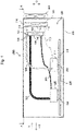
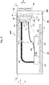
- FIG. 1 is a side perspective view showing the structure of the electronic device 1000 according to the first exemplary embodiment of the present invention when viewed from a side.
- Fig. 2 is a top perspective view showing a cross section along a line A - A in Fig. 1 .
- an X direction and -X direction shown in Fig. 1 and Fig. 2 correspond to directions approximately perpendicular to a first principal surface 730 and a second principal surface 740, respectively.
- a Y direction and -Y direction shown in Fig. 2 correspond to lead-out directions of a first pipe unit and a second pipe unit mentioned later, respectively.
- a G direction in Fig. 1 is a vertical direction. Further, the downward arrow of the G direction in Fig. 1 shows a direction of the gravitational force (vertically lower direction).
- an electronic substrate 200 will be described by using Fig. 1 and Fig. 2 before describing the configuration of the electronic device 1000.
- the electronic substrate 200 is composed of a substrate 210 and heat generating elements 220 and 230.
- the substrate 210 is, for example, a printed wiring board formed in a plate shape.
- This substrate 210 has a structure in which the heat generating elements 220 and 230 can be mounted thereon.
- a flame retardant material such as, for example, glass epoxy or the like is used for a material of the substrate 210.
- the heat generating elements 220 and 230 are, for example, electronic components such as a CPU (Central Processing Unit), an IC (Integrated Circuit), a power semiconductor, and the like.
- the heat generating element described above is an element which generates high-temperature heat when it operates.
- the heat generating elements 220 and 230 are mounted on the substrate 210 by soldering (not shown), for example.
- the heat generating elements 220 and 230 may be mounted on the substrate 210 by using for example, a socket (not shown) or the like.
- the structure of the electronic substrate 200 has been described above.
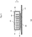
- Fig. 3 is a cross-sectional view showing a cross section along a line B - B in Fig. 2 .
- Fig. 4 is a perspective view showing a structure of a first heat dissipating unit 700 and a second heat dissipating unit 710.
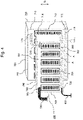
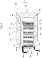
- Fig. 5 is a front view showing the structure of the first heat dissipating unit 700 and the second heat dissipating unit 710.
- the electronic device 1000 is composed of at least a cooling device 100 and a chassis 300.
- the chassis 300 accommodates the cooling unit 100.
- the cooling device 100 is composed of a first heat receiving unit 400 and a second heat receiving unit 410, a first vapor pipe 500 and a second vapor pipe 510, a first liquid pipe 600 and a second liquid pipe 610, a first heat dissipating unit 700 and a second heat dissipating unit 710, and a fan unit 800.
- the cooling device 100 can be used for various electronic devices such as, for example, a server equipped with the heat generating element, a personal computer, a router, a Light Emitting Diode (LED) projector, a projector which utilizes a Liquid Crystal Display (LCD) or a Digital Micro mirror Device (DMD), a communication equipment, a wireless equipment, a broadcast equipment, and the like.
- a server equipped with the heat generating element a personal computer, a router, a Light Emitting Diode (LED) projector, a projector which utilizes a Liquid Crystal Display (LCD) or a Digital Micro mirror Device (DMD), a communication equipment, a wireless equipment, a broadcast equipment, and the like.
- LCD Liquid Crystal Display
- DMD Digital Micro mirror Device
- the heat generating element 220 is cooled by circulating refrigerant between a first heat receiving unit 400 and the first heat dissipating unit 700 while changing the phase of refrigerant (gas phase ⁇ liquid phase).
- the heat generating element 230 is cooled by circulating refrigerant between a second heat receiving unit 410 and the second heat dissipating unit 710 while changing the phase of refrigerant (gas phase ⁇ liquid phase).
- the first heat receiving unit 400 and the first heat dissipating unit 700 are connected by the first vapor pipe 500 and the first liquid pipe 600.
- the second heat receiving unit 410 and the second heat dissipating unit 710 are connected by the second vapor pipe 510 and the second liquid pipe 610.
- the first heat receiving unit 400, the second heat receiving unit 410, the first heat dissipating unit 700, and the second heat dissipating unit 710 are formed in a hollow shape. Namely, each of these units has a hollow space therein.
- refrigerant (not shown) is held in a closed space composed of the hollow space of the first heat receiving unit 400, the hollow space of the first heat dissipating unit 700, the hollow inside the first vapor pipe 500, and the hollow inside the first liquid pipe 600.
- This refrigerant circulates between the first heat receiving unit 400 and the first heat dissipating unit 700 via the first vapor pipe 500 and the first liquid pipe 600.
- the specific gravity of vapor (gas-phase refrigerant) obtained by vaporizing refrigerant in the first heat receiving unit 400 is smaller than that of liquid-phase refrigerant, the vapor flows through the first vapor pipe 500 in the vertically upper direction and flows into the first heat dissipating unit 700.
- the gas-phase refrigerant is cooled inside the first heat dissipating unit 700 and condensed to a liquid.
- the liquid-phase refrigerant obtained by condensing the gas-phase refrigerant flows inside the first heat dissipating unit 700 in the vertically lower direction and flows into the first heat receiving unit 400 through the first liquid pipe 600.
- Refrigerant is also held in a closed space composed of the hollow space of the second heat receiving unit 410, the hollow space of the second heat dissipating unit 710, the hollow inside the second vapor pipe 510, and the hollow inside the second liquid pipe 610.
- the refrigerant circulates between the second heat receiving unit 410 and the second heat dissipating unit 710 via the second vapor pipe 510 and the second liquid pipe 610 like the circulation between the first heat receiving unit 400 and the first heat dissipating unit 700.
- the refrigerant is made of, for example, a high polymer material and the like.
- the refrigerant has a characteristic in which the refrigerant vaporizes at a high temperature and condenses at a low temperature.
- the first heat receiving unit 400 and the second heat receiving unit 410 are mounted on the heat generating element 220 and the heat generating element 230, respectively.
- the first heat receiving unit 400 and the second heat receiving unit 410 are thermally coupled to the heat generating elements 220 and 230, respectively.
- the first heat receiving unit 400 and the second heat receiving unit 410 receive the heat generated by the heat generating elements 220 and 230, respectively.
- the first heat receiving unit 400 and the second heat receiving unit 410 are disposed with the first heat dissipating unit 700 and the second heat dissipating unit 710, which will be mentioned later, along a direction (X direction and -X direction in Fig. 1 and Fig. 2 ) approximately perpendicular to the first principal surface 730 and the second principal surface 740, which will be described later.
- the first heat receiving unit 400 and the second heat receiving unit 410 are mounted on the heat generating elements 220 and 230 by using, for example, a screw (not shown) or the like, respectively.
- first heat receiving unit 400 and the second heat receiving unit 410 are pressed against the heat generating elements 220 and 230 at a pressure of, for example, about 100 to 500 kPa, respectively.
- a thermally conductive member such as, for example, aluminum, copper, or the like can be used as a material of the first heat receiving unit 400 and the second heat receiving unit 410.
- a material having good thermal conductivity for example, thermally conductive grease (not shown), a heat dissipation sheet (not shown), a graphite sheet (not shown), various thin metal films (not shown) using indium or the like, or the like) may be interposed between the first heat receiving unit 400 and the heat generating element 220, and between the second heat receiving unit 410 and the heat generating element 230.
- thermally conductive grease not shown
- heat dissipation sheet not shown
- a graphite sheet not shown
- various thin metal films (not shown) using indium or the like, or the like
- the internal structure of the first heat receiving unit 400 will be described by using Fig. 3 . Because the structure of the second heat receiving unit 410 is similar to that of the first heat receiving unit 400. Therefore, the description of the internal structure of the second heat receiving unit 410 will be omitted.
- the first heat receiving unit 400 includes a fin portion 401 for heat receiving unit, a refrigerant boiling portion 402, a vapor pipe side joining portion 403 for heat receiving unit, and a liquid pipe side joining portion 404 for heat receiving unit.
- the refrigerant boiling portion 402 is formed in an internal space of the first heat receiving unit 400. In the refrigerant boiling portion 402, the refrigerant changes from the liquid-phase refrigerant to the gas-phase refrigerant by the heat generated by the heat generating element 220.
- the fin portion 401 for heat receiving unit is formed in a plate shape, and a plurality of the fin portions 401 for heat receiving unit are arranged in the refrigerant boiling portion 402 of the first heat receiving unit 400.
- the fin portion 401 for heat receiving unit dissipates the heat generated by the heat generating element 220 and whereby, the temperature of the heat generating element 220 is reduced.
- the fin portion 401 for heat receiving unit has a large surface area.
- the fin portion 401 for heat receiving unit may have a bellows shape, a pinholder shape, or the like.
- the distance between the adjacent fin portions 401 for heat receiving unit is approximately 1 mm to 3 mm or more in order to prevent air bubbles produced by boiling of the refrigerant from staying on the surface of each fin portion 401 for heat receiving unit.
- the surface of the fin portion 401 for heat receiving unit may be polished to a surface finish roughness of, for example, several 10 ⁇ m to 100 ⁇ m by using a sandblasting process. This process increases the number of air bubbles produced on the surface of the fin portion 401 for heat receiving unit.
- the vapor pipe side joining portion 403 for heat receiving unit and the liquid pipe side joining portion 404 for heat receiving unit are formed in the first heat receiving unit 400.
- the first vapor pipe 500 is connected to the vapor pipe side joining portion 403 for heat receiving unit
- the first liquid pipe 600 is connected to the liquid pipe side joining portion 404 for heat receiving unit. Because the gas-phase refrigerant flows in the vertically upper direction, it is desirable that the vapor pipe side joining portion 403 for heat receiving unit is disposed on the vertically upper side of the first heat receiving unit 400.
- liquid pipe side joining portion 404 for heat receiving unit is disposed on the vertically lower side of in the first heat receiving unit 400 in order to prevent the gas-phase refrigerant from flowing into the first heat dissipating unit 700 through the first liquid pipe 600.
- first vapor pipe 500 the second vapor pipe 510, the first liquid pipe 600, and the second liquid pipe 610 will be described by using Fig. 1 and Fig. 2 .
- the first vapor pipe 500 connects the first heat receiving unit 400 and the first heat dissipating unit 700 and coveys the refrigerant from the first heat receiving unit 400 to the first heat dissipating unit 700.
- the first liquid pipe 600 connects the first heat receiving unit 400 and the first heat dissipating unit 700 and conveys the refrigerant from the first heat dissipating unit 700 to the first heat receiving unit 400.
- the first vapor pipe 500 and the first liquid pipe 600 are collectively called the first pipe unit. Namely, in order to circulate the refrigerant between the first heat receiving unit 400 and the first heat dissipating unit 700, the first pipe unit connects the first heat receiving unit 400 and the first heat dissipating unit 700.
- the second vapor pipe 510 connects the second heat receiving unit 410 and the second heat dissipating unit 710 and conveys the refrigerant from the second heat receiving unit 410 to the second heat dissipating unit 710.
- the second liquid pipe 610 connects the second heat receiving unit 410 and the second heat dissipating unit 710 and conveys the refrigerant from the second heat dissipating unit 710 to the second heat receiving unit 410.
- the second vapor pipe 510 and the second liquid pipe 610 are collectively called the second pipe unit. Namely, in order to circulate the refrigerant between the second heat receiving unit 410 and the second heat dissipating unit 710, the second pipe unit connects the second heat receiving unit 410 and the second heat dissipating unit 710.
- the inner diameter of the first vapor pipe 500, the inner diameter of the second vapor pipe 510, the inner diameter of the first liquid pipe 600, and the inner diameter of the second liquid pipe 610 can be appropriately determined according to the required cooling performance of the electronic device 1000.
- the inner diameter of the first vapor pipe 500 and the inner diameter of the second vapor pipe 510 may be 15 mm and the inner diameter of the first liquid pipe 600 and the inner diameter of the second liquid pipe 610 may be 10 mm. It is desirable that a pipe having a relatively large inner diameter is used for the first vapor pipe 500 and the second vapor pipe 510 so to minimize pressure loss.
- first liquid pipe 600 and the second liquid pipe 610 it is desirable that a pipe having a relatively small inner diameter is used for the first liquid pipe 600 and the second liquid pipe 610.
- the inner diameters of the first liquid pipe 600 and the second liquid pipe 610 may be made smaller than those of the first vapor pipe 500 and the second vapor pipe 510. This prevents the gas-phase refrigerant from flowing backward into the first heat dissipating unit 700 and the second heat dissipating unit 710 in the first heat receiving unit 400 and the second heat receiving unit 410.
- the inner diameters of the first liquid pipe 600 and the second liquid pipe 610 can be made equal to the inner diameters of the first vapor pipes 500 and the second vapor pipe 510. As a result, the fluidity of the refrigerant flowing in the first liquid pipe 600 and the second liquid pipe 610 is improved.
- the first vapor pipe 500 and the first liquid pipe 600 of the first pipe unit are led out from the first heat receiving unit 400 in the Y direction.
- the second vapor pipe 510 and the second liquid pipe 610 of the second pipe unit are led out from the second heat receiving unit 410 in the - Y direction.
- the lead-out direction (Y direction in Fig. 2 ) of the first pipe unit that is led out from the first heat receiving unit 400 is opposite to the lead-out direction (-Y direction in Fig. 2 ) of the second pipe unit that is led out from the second heat receiving unit 410.
- the first heat dissipating unit 700 is composed of an upper tank portion 701 (especially refer to Fig. 5 ), a lower tank portion 702 (especially refer to Fig. 5 ), a plurality of connection pipe portions 703 (especially refer to Fig. 5 ), a plurality of fin portions 704 for heat dissipating unit (especially refer to Fig. 5 ), a vapor pipe side joining portion 705 for heat dissipating unit, a liquid pipe side joining portion 706 for heat dissipating unit, a third principal surface 720 (especially refer to Fig. 1 ), and the first principal surface 730 (especially refer to Fig. 1 ).
- an upper tank portion 701 especially refer to Fig. 5
- a lower tank portion 702 especially refer to Fig. 5
- a plurality of connection pipe portions 703 especially refer to Fig. 5
- a plurality of fin portions 704 for heat dissipating unit especially refer to Fig. 5
- a vapor pipe side joining portion 705 for heat
- the upper tank portion 701 (the portion surrounded by a dotted line in Fig. 5 ) and the lower tank portion 702 (the portion surrounded by a dotted line in Fig. 5 ) are connected by a plurality of the connection pipe portions 703 (in Fig. 5 , seven connection pipe portions are shown).
- the connection pipe portions 703 in Fig. 5 , seven connection pipe portions are shown.
- the first vapor pipe 500 is connected to the vapor pipe side joining portion 705 for heat dissipating unit disposed in the upper tank portion 701 and the first liquid pipe 600 is connected to the liquid pipe side joining portion 706 for heat dissipating unit disposed in the lower tank portion 702.
- a passage through which air passes is formed between a plurality of the connection pipes 703.
- a plurality of the fin portions 704 for heat dissipating unit are disposed on the passage of air. Namely, especially, as shown in Fig. 5 , a plurality of the fin portions 704 for heat dissipating unit are disposed on the passage of air formed between a plurality of the connection pipe portions 703.
- the structure of the second heat dissipating unit 710 is similar to that of the first heat dissipating unit 700. Namely, as shown in Figs. 1 , 2 , 4 and 5 , the second heat dissipating unit 710 is composed of an upper tank portion 711 (especially refer to Fig. 5 ), a lower tank portion 712 (especially refer to Fig. 5 ), a plurality of connection pipe portions 713 (especially refer to Fig. 5 ), a plurality of fin portions 714 for heat dissipating unit (especially refer to Fig.
- a vapor pipe side joining portion 715 for heat dissipating unit a liquid pipe side joining portion 716 for heat dissipating unit
- the second principal surface 740 especially refer to Fig. 1
- a fourth principal surface 750 especially refer to Fig. 1 .
- the upper tank portion 711 the portion surrounded by a dotted line in Fig. 5
- the lower tank portion 712 the portion surrounded by a dotted line in Fig. 5
- a plurality of the connection pipe portions 713 in Fig. 5 , seven connection pipe portions are shown).
- the closed space By connecting the upper tank portion 711, the lower tank portion 712, and a plurality of the connection pipes 713, the closed space is formed.
- the second vapor pipe 510 is connected to the vapor pipe side joining portion 715 for heat dissipating unit disposed in the upper tank portion 711 and the second liquid pipe 610 is connected to the liquid pipe side joining portion 716 for heat dissipating unit disposed in the lower tank portion 712.
- a passage through which air passes is formed between a plurality of the connection pipes 713.
- a plurality of the fin portions 714 for heat dissipating unit are disposed on the passage of air. Namely, especially, as shown in Fig. 5 , a plurality of the fin portions 714 for heat dissipating unit are disposed between a plurality of the connection pipe portions 713.
- the first heat dissipating unit 700 and the second heat dissipating unit 710 dissipate the heat received by the first heat receiving unit 400 and the second heat receiving unit 410, respectively. As shown in Fig. 1 and Fig. 2 , the first heat dissipating unit 700 and the second heat dissipating unit 710 are disposed with the first heat receiving unit 400 and the second heat receiving unit 410 along a direction (X direction and -X direction in Figs. 1 and 2 ) approximately perpendicular to the first principal surface 730 and the second principal surface 740.
- the first heat dissipating unit 700 and the second heat dissipating unit 710 are formed in a flat plate shape. Further, the first principal surface 730 of the first heat dissipating unit 700 and the second principal surface 740 of the second heat dissipating unit 710 are arranged so as to face to each other.
- the first principal surface 730 and the second principal surface 740 are formed in a rectangular shape. As shown in Fig. 2 , a distance between both end sides of the first principal surface 730 and a distance between both end sides of the second principal surface 740 are set in accordance with the distance ( ⁇ in Fig. 2 ) between the inner walls of the chassis 300. Namely, the end sides of the first principal surface 730 and the end sides of the second principal surface 740 that extend in the Y direction and -Y direction (horizontal direction) are in contact with the inner wall of the chassis 300.
- Each of the first heat dissipating unit 700 and the second heat dissipating unit 710 has the hollow space therein and store refrigerant (A in Figs. 4 and 5 ) in the hollow space.
- the upper tank portions 701 and 711 are disposed at the locations vertically higher than the locations of the lower tank portions 702 and 712, respectively.
- connection pipe portion 703 of the first heat dissipating unit 700 connects the upper tank portion 701 and the lower tank portion 702.
- the connection pipe portion 713 of the second heat dissipating unit 710 connects the upper tank portion 711 and the lower tank portion 712.
- a plurality of the connection pipe portions 703 and a plurality of the connection pipe portions 713 are disposed.
- the fin portion 704 for heat dissipating unit and the fin portion 714 for heat dissipating unit are disposed between the connection pipe portions 703.
- the fin portion 704 for heat dissipating unit and the fin portion 714 for heat dissipating unit dissipate heat of the gas-phase refrigerant conveyed from the upper tank portion 701 and the upper tank portion 711, respectively.
- the refrigerant changes from the gas-phase refrigerant to the liquid-phase refrigerant and the liquid-phase refrigerant flow to the lower tank portions 702 and 712 through the connection pipe portions 703 and 713, respectively.
- Each of the fin portion 704 for heat dissipating unit and the fin portion 714 for heat dissipating unit is composed of a plurality of fins and has a structure in which air can flow through the plurality of the fins. Namely, as shown in Fig. 1 and Fig. 2 , in the first heat dissipating unit 700, in an area of the fin portion 704 for heat dissipating unit, air passes in the direction (X direction and -X direction in Figs. 1 and 2 ) approximately perpendicular to the first principal surface 720 and the third principal surface 730.
- air passes in the direction (X direction and -X direction in Figs. 1 and 2 ) approximately perpendicular to the second principal surface 740 and the fourth principal surface 750.
- the vapor pipe side joining portion 705 for heat dissipating unit and the vapor pipe side joining portion 715 for heat dissipating unit are formed in the upper tank portion 701 and the upper tank portion 711, respectively.
- the first vapor pipe 500 and the second vapor pipe 510 are connected to the vapor pipe side joining portion 705 for heat dissipating unit and the vapor pipe side joining portion 715 for heat dissipating unit, respectively.
- the liquid pipe side joining portion 706 for heat dissipating unit and the liquid pipe side joining portion 716 for heat dissipating unit are formed in the lower tank portion 702 and the lower tank portion 712, respectively.
- the first liquid pipe 600 and the second liquid pipe 610 are connected to the liquid pipe side joining portion 706 for heat dissipating unit and the liquid pipe side joining portion 716 for heat dissipating unit, respectively.
- a fan unit 800 As shown in Fig. 1 and Fig. 2 , the fan unit 800 is disposed outside the chassis 300 (shown in a right part of Fig. 1 and Fig. 2 ). As shown in Fig. 1 and Fig. 2 , the fan unit 800 blows air to a facing area in which the first principal surface 730 and the second principal surface 740 face each other. As described above, in the first heat dissipating unit 700, in the area of the fin portion 704 for heat dissipating unit, air passes in the direction (X direction and -X direction in Figs. 1 and 2 ) approximately perpendicular to the first principal surface 720 and the third principal surface 730.
- air passes in the direction (X direction and -X direction in Figs. 1 and 2 ) approximately perpendicular to the second principal surface 740 and the fourth principal surface 750. Accordingly, of the facing area in which the first principal surface 730 and the second principal surface 740 face each other in an area in which at least the fin portion 704 for heat dissipating unit and the fin portion 714 for heat dissipating unit overlap each other, air passes in the direction (X direction and -X direction in Figs. 1 and 2 ) approximately perpendicular to the second principal surface 740 and the fourth principal surface 750.
- the fan unit 800 sends air to the area in which at least the fin portion 704 for heat dissipating unit and the fin portion 714 for heat dissipating unit overlap each other in the facing area in which the first principal surface 730 and the second principal surface 740 face to each other.
- the facing area described above corresponds to an area in which the first heat dissipating unit 700 and the second heat dissipating unit 710 overlap each other when the first heat dissipating unit 700 and the second heat dissipating unit 710 are viewed in the X direction and the -X direction as shown in Fig. 5 .
- the fan unit 800 is disposed in such a way that the direction in which air is sent corresponds to the direction (X direction and -X direction in Figs. 1 and 2 ) approximately perpendicular to the first principal surface 730 and the second principal surface 740.
- the fan unit 800 sends air in the X direction shown in Fig. 1 and Fig. 2 in the facing area. Namely, airflow generated by the fan unit 800 flows through the third principal surface 720, the first principal surface 730, the second principal surface 740, and the fourth principal surface 750 in this order in at least the facing area and air is discharged outside the chassis 300
- the heat generating elements 220 and 230 when power of the cooling device 100 is turned on, mainly the heat generating elements 220 and 230 generate heat, and the temperature of the electronic substrate 200 increases.
- the first heat receiving unit 400 and the second heat receiving unit 410 receive heat generated by the heat generating elements 220 and 230, respectively.
- the first heat dissipating unit 700 and the second heat dissipating unit 710 dissipate the heat received by the first heat receiving unit 400 and the second heat receiving unit 410, respectively.
- refrigerant is circulated while changing the phase of refrigerant and whereby the heat generated by the heat generating elements 220 and 230 on the electronic substrate 200 are dissipated.
- the fan unit 800 air in the chassis 300 flows to the third principal surface 720, the first principal surface 730, the second principal surface 740, and the fourth principal surface 750 in this order in at least the facing area and air is discharged outside the chassis 300.
- the first heat dissipating unit 700 and the second heat dissipating unit 710 are cooled by air and the heat generated by the heat generating elements 220 and 230 on the electronic substrate 200 can be efficiently dissipated.
- the cooling device 100 includes the first heat receiving unit 400, the second heat receiving unit 410, the first heat dissipating unit 700, and the second heat dissipating unit 710.
- the first heat receiving unit 400 and the second heat receiving unit 410 receive the heat generated by the heat generating elements 220 and 230, respectively.
- the first heat dissipating unit 700 dissipates the heat received by the first heat receiving unit 400.
- the second heat dissipating unit 710 dissipates the heat received by the second heat receiving unit 410.
- first heat dissipating unit 700 and the second heat dissipating unit 710 have a flat plate shape and have a structure in which air passes in a direction approximately perpendicular to the principal surface having a flat plate shape.
- first main surface 730 that is the principal surface having a flat plate shape in the first heat dissipating unit 700 and the second principal surface 740 that is the principal surface having a flat plate shape in the second heat dissipating unit 710 are arranged so as to face each other.
- the size of the cooling device 100 can be reduced in comparison with a case in which the first heat dissipating unit 700 and the second heat dissipating unit 710 are disposed in parallel. Further, the first heat dissipating unit 700 dissipates the heat generated by the heat generating element 220 and the second heat dissipating unit 710 dissipates the heat generated by the heat generating element 230. Namely, the first heat dissipating unit 700 and the second heat dissipating unit 710 of the cooling device 100 dissipate the heat generated by the heat generating elements 220 and 230, respectively. Therefore, a heat dissipation function is not degraded.
- the first heat dissipating unit 700 and the second heat dissipating unit 710 are arranged so as to face to each other. Therefore, the size of the cooling device 100 can be reduced without degrading the function to dissipate the heat generated by the heat generating elements 220 and 230.
- refrigerant is circulated between the first heat receiving unit 400 and the first heat dissipating unit 700 while changing the phase of the refrigerant (gas phase ⁇ liquid phase) and whereby the heat generating element 220 can be cooled.
- refrigerant is circulated between the second heat receiving unit 410 and the second heat dissipating unit 710 while changing the phase of the refrigerant (gas phase ⁇ liquid phase) and whereby the heat generating element 230 can be cooled.
- the cooling device 100 uses a phase change cooling system. Therefore, the thermal resistances of the heat generating elements 220 and 230 can be reduced compared with an air-cooling type cooling device.
- the cooling device 100 includes the fan unit 800.
- the fan unit 800 sends air to the facing area in which the first principal surface 730 and the second main surface 740 face to each other in the first principal surface 730 and the second principal surface 740.
- the fan unit 800 can directly send air to both the first heat dissipating unit 700 and the second heat dissipating unit 710, the first heat dissipating unit 700 and the second heat dissipating unit 710 can be cooled at the same time. As a result, the heat generated by the heat generating elements 220 and 230 can be efficiently dissipated.
- the fan unit 800 has to be provided for each of the first heat dissipating unit 700 and the second heat dissipating unit 710.
- the first principal surface 730 and the second principal surface 740 are arranged so as to face to each other in order to make the facing area, when air is sent to the facing area by using one fan unit 800, both the first heat dissipating unit 700 and the second heat dissipating unit 710 can be cooled. As a result, the cost, the power consumption, and the size of the cooling device 100 can be reduced.
- the first principal surface 730 and the second principal surface 740 are formed in a rectangular shape.
- the distance between the both edges in a surface direction (the Y direction and the -Y direction in Fig. 2 ) of the first principal surface 730 and the second principal surface 740 corresponds to the distance ⁇ between the inner walls of the chassis 300 which accommodates the first heat receiving unit 400, the second heat receiving unit 410, the first heat dissipating unit 700, and the second heat dissipating unit 710.
- the dissipation areas of the first heat dissipating unit 700 and the second heat dissipating unit 710 can be made maximum.
- the heat generated by the heat generating elements 220 and 230 can be further effectively dissipated.
- the heat dissipation areas of the first heat dissipating unit 700 and the second heat dissipating unit 710 can be made large in a horizontal direction (the Y direction and the -Y direction in Fig. 2 ) that is a direction approximately perpendicular to the vertical direction, the pressure loss of refrigerant flowing in the vertical direction can be reduced in the first heat dissipating unit 700 and the second heat dissipating unit 710. As a result, the fluidity of the refrigerant in the first heat dissipating unit 700 and the second heat dissipating unit 710 can be increased and the heat generated by the heat generating elements 220 and 230 can be further effectively dissipated.
- the first heat receiving unit 400, the second heat receiving unit 410, the first heat dissipating unit 700, and the second heat dissipating unit 710 are disposed along the direction (X direction and -X direction in Fig 1 ) approximately perpendicular to the first principal surface 730 and the second principal surface 740. Therefore, the size of the cooling device 100 can be made small in comparison with a case in which the first heat dissipating unit 700 and the second heat dissipating unit 710 are disposed side by side.
- the cooling device 100 includes the first pipe unit and the second pipe unit.
- the first pipe unit connects the first heat receiving unit 400 and the first heat dissipating unit 700.
- the second pipe unit connects the second heat receiving unit 410 and the second heat dissipating unit 710.
- the lead-out direction (the Y direction in Fig. 2 ) in which the first pipe unit is leaded out from the first heat receiving unit 400 is opposite to the lead-out direction (the -Y direction in Fig. 2 ) in which the second pipe unit is leaded out from the second heat receiving unit 410.
- the electronic device 1000 includes the cooling device 100 and the chassis 300.
- the chassis 300 accommodates the cooling device 100.
- the cooling device 100 includes the first heat receiving unit 400 and the second heat receiving unit 410 which receive the heat generated by the heat generating elements 220 and 230 respectively, the first heat dissipating unit 700 which dissipates the heat received by the first heat receiving unit 400, and the second heat dissipating unit 710 which dissipates the heat received by the second heat receiving unit 410.
- the first heat dissipating unit 700 and the second heat dissipating unit 710 have a flat plate shape and have a structure in which air passes in a direction approximately perpendicular to the principal surface having the flat plate shape and wherein the first principal surface 730 that is the principal surface having a flat plate shape in the first heat dissipating unit 700 and the second principal surface 740 that is the principal surface having a flat plate shape in the second heat dissipating unit 710 are arranged so as to face to each other.
- This electronic device 1000 has functions and effects similar to those of the cooling device 100 mentioned above.
- FIG. 6 is a side perspective view showing a structure of an electronic device 1000a including the cooling device 100a according to the second exemplary embodiment of the present invention when viewed from the side.
- Fig. 7 is a top perspective view showing a cross section along a line C - C in Fig. 6 .
- Fig. 8 is a perspective view showing a connection relationship between the first heat dissipating unit 700 / the second heat dissipating unit 710 and a cover portion 900.
- the electronic device 1000a is composed of the cooling device 100a and the chassis 300.
- the cooling device 100a is composed of the first heat receiving unit 400, the second heat receiving unit 410, the first vapor pipe 500, the second vapor pipe 510, the first liquid pipe 600, the second liquid pipe 610, the first heat dissipating unit 700, the second heat dissipating unit 710, the fan unit 800, and the cover portion 900.
- the cooling device 100a shown in Fig. 6 further includes the cover portion 900. This is a difference between the cooling device 100 shown in Fig. 1 and the cooling device 100a shown in Fig. 6 . Therefore, in the following description, the description about the structure that is the same as the structure shown in Fig. 1 to Fig. 5 will be omitted.
- the cover portion 900 connects the outer peripheral edge of the first principal surface 730 and the outer peripheral edge of the second principal surface 740.
- a metal such as aluminum, copper, or the like or a resin such as a plastic, rubber, or the like may be used for a material of the cover portion 900.
- the cover portion 900 may be fixed to the outer peripheral edges of the first principal surface 730 and the second principal surface 740 by using, for example, a screw or the like.
- cover portion 900 includes a vapor pipe side opening 901 for cover portion and a liquid pipe side opening 902 for cover portion.
- the vapor pipe side opening 901 for cover portion is formed at a position that matches the vapor pipe side joining portion 715 for heat dissipating unit of the second heat dissipating unit 710. Further, the inner diameter of the vapor pipe side opening 901 for cover portion corresponds to the outer diameter of the second vapor pipe 510.
- the liquid pipe side opening 902 for cover portion is formed at a position that matches the liquid pipe side joining portion 716 for heat dissipating unit of the second heat dissipating unit 710. Further, the inner diameter of the liquid pipe side opening 902 for cover portion corresponds to the outer diameter of the second liquid pipe 610.
- the cooling device 100a includes the cover portion 900.
- the cover portion 900 connects the outer peripheral edge of the first principal surface 730 and the outer peripheral edge of the second principal surface 740.
- the air flowing in the third principal surface 720 flows out from the fourth principal surface 750.
- the first heat dissipating unit 700 and the second heat dissipating unit 710 can be more effectively cooled, and the heat generated by the heat generating elements 220 and 230 can be more effectively dissipated.
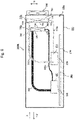
- FIG. 9 is a side perspective view showing a structure of an electronic device 1000b including the cooling device 100b according to the third exemplary embodiment of the present invention when viewed from the side.
- Fig. 10 is a perspective view showing a connection relationship between the first heat dissipating unit 700 and a first liquid pipe 600a and a connection relationship between the second heat dissipating unit 710 and a second liquid pipe 610a.
- the electronic device 1000b is composed of the cooling device 100b and the chassis 300.
- the cooling device 100b is composed of the first heat receiving unit 400, the second heat receiving unit 410, the first vapor pipe 500, the second vapor pipe 510, the first liquid pipe 600a, the second liquid pipe 610a, a first heat dissipating unit 700a, a second heat dissipating unit 710a, and the fan unit 800.
- the structure shown in Fig. 1 is compared with the structure shown in Fig. 9 .
- the first liquid pipe 600 is connected to the third principal surface 720.
- the second liquid pipe 610 is connected to the second principal surface 740.
- the first liquid pipe 600a is connected to a vertically lower side surface (a bottom face) 760 of the first heat dissipating unit 700a.
- the second liquid pipe 610a is connected to a vertically lower side surface (a bottom face) 770 of the second heat dissipating unit 710a.
- a liquid pipe side joining portion 706a for heat dissipating unit of the first heat dissipating unit 700a is formed on the vertically lower side surface (the bottom face) 760.
- a liquid pipe side joining portion 716a for heat dissipating unit of the second heat dissipating unit 710a is formed in the vertically lower side surface (the bottom face) 770.
- the first liquid pipe 600a is connected to the liquid pipe side joining portion 706a for heat dissipating unit of the first heat dissipating unit 700a.
- the first liquid pipe 600a is connected to the vertically lower side surface 760 of the first heat dissipating unit 700a.
- the second liquid pipe 610a is connected to the liquid pipe side joining portion 716a for heat dissipating unit of the second heat dissipating unit 710a.
- the second liquid pipe 610a is connected to the vertically lower side surface 770 of the second heat dissipating unit 710a.
- first liquid pipe 600a and the second liquid pipe 610a are connected to the vertically lower side surface 760 of the first heat dissipating unit 700a and the vertically lower side surface 770 of the second heat dissipating unit 710a, respectively.
- This structure is most preferable.
- one of the first liquid pipe 600a and the second liquid pipe 610a may be connected to the vertically lower side surface.
- the cooling device 100b in order to circulate refrigerant between the first heat receiving unit 400 and the first heat dissipating unit 700a, includes the first pipe unit and the second pipe unit.
- the first pipe unit connects the first heat receiving unit 400 and the first heat dissipating unit 700a.
- the second pipe unit connects the second heat receiving unit 410 and the second heat dissipating unit 710a.
- the first pipe unit includes the first vapor pipe 500 and the first liquid pipe 600a.
- the first vapor pipe 500 connects the first heat receiving unit 400 and the first heat dissipating unit 700a.
- the first liquid pipe 600a connects the first heat receiving unit 400 and the first heat dissipating unit 700a.
- the second pipe unit includes the second vapor pipe 510 and the second liquid pipe 610a.
- the second vapor pipe 510 connects the second heat receiving unit 410 and the second heat dissipating unit 710a.
- the second liquid pipe 610a connects the second heat receiving unit 410 and the second heat dissipating unit 710a.
- At least one of a structure in which the first liquid pipe 600a is connected to the vertically lower side surface 760 of the first heat dissipating unit 700a and a structure in which the second liquid pipe 610a is connected to the vertically lower side surface 770 of the second heat dissipating unit 710a is used.
- the gas-phase refrigerant from the upper tank portions 701 changes to the liquid-phase refrigerant and the liquid-phase refrigerant flows through the connection pipe portion 703 in the vertically lower direction and flows into the lower tank portion 702 and similarly, the gas-phase refrigerant from the upper tank portion 711 changes to the liquid-phase refrigerant and the liquid-phase refrigerant flows through the connection pipe portion 713 in the vertically lower direction and flows into the lower tank portion 712.
- the liquid-phase refrigerant in the lower tank portions 702 and 712 flow into the first liquid pipe 600a and the second liquid pipe 610a, respectively.
- the first liquid pipe 600a and the second liquid pipe 610a are connected to the vertically lower side surface (the bottom face) 760 of the first heat dissipating unit 700a and the vertically lower side surface (the bottom face) 770 of the second heat dissipating unit 710a, respectively.
- the liquid-phase refrigerant in the lower tank portion 702 of the first heat dissipating unit 700a and the liquid-phase refrigerant in the lower tank portion 712 of the second heat dissipating unit 710a can be smoothly conveyed to the first liquid pipe 600a and the second liquid pipe 610a, respectively, in comparison with, for example, a case in which the first liquid pipe 600a and the second liquid pipe 610a are connected to the surfaces (the side faces or the top faces other than the bottom faces) other than the vertically lower side surface (the bottom face) 760 and the vertically lower side surface (the bottom face) 770.
- the liquid-phase refrigerant can more smoothly flow out from the lower tank portion 702 of the first heat dissipating unit 700a and the lower tank portion 712 of the second heat dissipating unit 710a. Therefore, in the first heat dissipating unit 700a and the second heat dissipating unit 710a, the liquid-phase refrigerant in the lower tank portion 702 and the liquid-phase refrigerant in the lower tank portion 712 can easily flow into the first liquid pipe 600a and the second liquid pipe 610a without resistance, respectively.
- the refrigerant can be more effectively circulated between the first heat receiving unit 400 and the first heat dissipating unit 700a.
- the refrigerant can be more effectively circulated between the second heat receiving unit 410 and the second heat dissipating unit 710a. Therefore, the heat generated by the heat generating elements 220 and 230 can be more effectively dissipated.
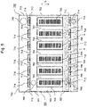
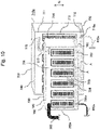
- FIG. 11 is a side perspective view showing a structure of an electronic device 1000c including the cooling device 100c according to the fourth exemplary embodiment of the present invention when viewed from the side.
- Fig. 12 is a top perspective view showing a cross section along a line D - D in Fig. 11 . Further, in Fig. 11 and Fig. 12 , the same reference numbers are used for the elements having the same function as the elements shown in Fig. 1 to Fig. 10 .
- the electronic device 1000c is composed of the cooling device 100c and the chassis 300.
- the cooling device 100c is composed of a first heat receiving unit 400a, a second heat receiving unit 410a, the first vapor pipe 500, the second vapor pipe 510, the first liquid pipe 600, the second liquid pipe 610, the first heat dissipating unit 700, the second heat dissipating unit 710, and the fan unit 800.
- the structure shown in Fig. 1 is compared with the structure shown in Fig. 11 .
- the first heat receiving unit 400 and the second heat receiving unit 410 receive the heat generated by the heat generating elements 220 and 230, respectively.
- the first heat receiving unit 400a and the second heat receiving unit 410a receive the heat generated by a plurality of the heat generating elements 220 and a plurality of the heat generating elements 230, respectively.
- This is a difference between the structure shown in Fig. 1 and the structure shown in Fig. 11 .
- the description about the structure that is the same as the structure shown in Fig. 1 to Fig. 10 will be omitted.
- the first heat receiving unit 400a is mounted on the plurality of the heat generating elements 220.
- the first heat receiving unit 400a receives the heat generated by the plurality of the heat generating elements 220.
- the second heat receiving unit 410a is mounted on a plurality of the heat generating elements 230.
- the second heat receiving unit 410a receives the heat generated by a plurality of the heat generating elements 230.
- Fig. 11 and Fig. 12 show a structure in which the first heat receiving unit 400a and the second heat receiving unit 410a receive the heat generated by a plurality of the heat generating elements 220 and a plurality of the heat generating elements 230, respectively.
- a structure in which either the first heat receiving unit 400a or the second heat receiving unit 410a receives the heat generated by a plurality of the heat generating elements may be used.
- the number of the heat generating elements is two.
- the number of the heat generating elements is not limited to two.
- the cooling device 100c As described above, in the cooling device 100c according to the fourth exemplary embodiment of the present invention, at least one of a structure in which the first heat receiving unit 400a receives the heat generated by a plurality of the heat generating elements 220 and a structure in which the second heat receiving unit 410a receives the heat generated by a plurality of the heat generating elements 230 can be used as the structure of the heat receiving unit.
Landscapes
- Engineering & Computer Science (AREA)
- Microelectronics & Electronic Packaging (AREA)
- Physics & Mathematics (AREA)
- Thermal Sciences (AREA)
- General Engineering & Computer Science (AREA)
- Computer Hardware Design (AREA)
- Life Sciences & Earth Sciences (AREA)
- Sustainable Development (AREA)
- Mechanical Engineering (AREA)
- Cooling Or The Like Of Electrical Apparatus (AREA)
- Cooling Or The Like Of Semiconductors Or Solid State Devices (AREA)
Claims (9)
- Kühlvorrichtung (100), umfassendeine erste Wärmeaufnahmeeinheit (400) und eine zweite Wärmeaufnahmeeinheit (410), die von Wärmeerzeugungselementen (220, 230) erzeugte Wärme aufnehmen;eine erste Wärmeableitungseinheit (700), die eine erste Hauptfläche (730) aufweist und die von der ersten Wärmeaufnahmeeinheit (400) aufgenommene Wärme ableitet; undeine zweite Wärmeableitungseinheit (710), die eine zweite Hauptfläche (740) aufweist und die von der zweiten Wärmeaufnahme- (410) -einheit aufgenommene Wärme ableitet;eine erste Rohreinheit (500, 600), die die erste Wärmeaufnahmeeinheit (400) und die erste Wärmeableitungseinheit (700) zum Zirkulierenlassen von Kältemittel zwischen der ersten Wärmeaufnahmeeinheit (400) und der ersten Wärmeableitungseinheit (700) verbindet; undeine zweite Rohreinheit (510, 610), die die zweite Wärmeaufnahmeeinheit (410) und die zweite Wärmeableitungseinheit (710) zum Zirkulierenlassen von Kältemittel zwischen der zweiten Wärmeaufnahmeeinheit (410) und der zweiten Wärmeableitungseinheit (710) verbindet; wobeidie erste Rohreinheit (500, 600) ein erstes Dampfrohr (500) und ein erstes Flüssigkeitsrohr (600) beinhaltet, wobei das erste Dampfrohr (500) die erste Wärmeaufnahmeeinheit (400) und die erste Wärmeableitungseinheit (700) verbindet und Kältemittel von der ersten Wärmeaufnahmeeinheit (400) zu der ersten Wärmeableitungseinheit leitet, das erste Flüssigkeitsrohr die erste Wärmeaufnahmeeinheit (400) und die erste Wärmeableitungseinheit (700) verbindet und Kältemittel von der ersten Wärmeableitungseinheit (700) zu der ersten Wärmeaufnahmeeinheit (400) leitet;die zweite Rohreinheit (510, 610) ein zweites Dampfrohr (510) und ein zweites Flüssigkeitsrohr (610) beinhaltet, wobei das zweite Dampfrohr (510) die zweite Wärmeaufnahmeeinheit (410) und die zweite Wärmeableitungseinheit (710) verbindet und Kältemittel von der zweiten Wärmeaufnahmeeinheit (410) zu der zweiten Wärmeableitungseinheit (710) leitet, das zweite Flüssigkeitsrohr (610) die zweite Wärmeaufnahmeeinheit (410) und die zweite Wärmeableitungseinheit (710) verbindet und Kältemittel von der zweiten Wärmeableitungseinheit (710) zu der zweiten Wärmeaufnahmeeinheit (410) leitet;die erste Hauptfläche (730) und die zweite Hauptfläche (740) so angeordnet sind, dass sie einander gegenüberliegen, wobeiLuft die erste Wärmeableitungseinheit (700) und die zweite Wärmeableitungseinheit (710) in einer Richtung, die zu der ersten Hauptfläche (730) und der zweiten Hauptfläche (740) etwa lotrecht ist, und von der ersten Wärmeableitungseinheit (700) hin zu der zweiten Wärmeableitungseinheit (710) durchströmt unddas erste Dampfrohr (500) mit einem ersten Ende der ersten Wärmeableitungseinheit (700) verbunden ist; unddas zweite Dampfrohr (510) mit einem zweiten Ende der zweiten Wärmeableitungseinheit (710) verbunden ist, das neben einem zweiten Ende der ersten Wärmeableitungseinheit (700) liegt, wobei das zweite Ende der ersten Wärmeableitungseinheit (700) ein dem ersten Ende der ersten Wärmeableitungseinheit (700) entgegengesetztes Ende ist.
- Kühlvorrichtung nach Anspruch 1, ferner umfassend:
eine Gebläseeinheit (800), die Luft in einen Gegenüberlagebereich bläst, in dem die erste Hauptfläche (730) und die zweite Hauptfläche (740) einander gegenüberliegen, wobei der Gegenüberlagebereich Teil der ersten Hauptfläche (730) und der zweiten Hauptfläche (740) ist. - Kühlvorrichtung nach Anspruch 1 oder Anspruch 2, ferner umfassend:
einen Abdeckungsteil (900), der einen äußeren Umfangsrand der ersten Hauptfläche (730) und einen äußeren Umfangsrand der zweiten Hauptfläche (740) verbindet. - Kühlvorrichtung nach einem der Ansprüche 1 bis 3, wobeidie erste Hauptfläche (730) und die zweite Hauptfläche (740) jeweils in einer rechteckigen Form ausgebildet sind undein Abstand in einer Oberflächenrichtung zwischen beiden Endseiten der ersten Hauptfläche und ein Abstand in einer Oberflächenrichtung zwischen beiden Endseiten der zweiten Hauptfläche einem Abstand zwischen Innenwänden eines Gehäuses (300) entsprechen, in dem die erste Wärmeaufnahmeeinheit und die zweite Wärmeaufnahmeeinheit (410), die erste Ableitungseinheit und die zweite Wärmeableitungseinheit (710) untergebracht sind.
- Kühlvorrichtung nach einem der Ansprüche 1 bis 4, bei der die erste und die zweite Wärmeaufnahmeeinheit (400, 410) und die erste und die zweite Wärmeableitungseinheit (700, 710) entlang einer Richtung angeordnet sind, die zu der ersten und der zweiten Hauptfläche etwa lotrecht sind.
- Kühlvorrichtung nach einem der Ansprüche 1 bis 5; wobei
eine Herausführungsrichtung, in der die erste Rohreinheit aus der ersten Wärmeaufnahmeeinheit (400) herausgeführt wird, einer Herausführungsrichtung entgegengesetzt ist, in der die zweite Rohreinheit aus der zweiten Wärmeaufnahmeeinheit (410) herausgeführt wird. - Kühlvorrichtung nach einem der Ansprüche 1 bis 5; wobei
das erste Flüssigkeitsrohr mit einer vertikal unteren Seitenfläche der ersten Wärmeableitungseinheit (700) verbunden ist oder das zweite Flüssigkeitsrohr mit einer vertikal unteren Seitenfläche der zweiten Wärmeableitungseinheit (710) verbunden ist. - Kühlvorrichtung nach einem der Ansprüche 1 bis 7, bei der
wenigstens eine von der ersten Wärmeaufnahmeeinheit (400) und der zweiten Wärmeaufnahmeeinheit (410) von mehreren Wärmeerzeugungselementen erzeugte Wärme aufnimmt. - Elektronische Vorrichtung, umfassend:
die Kühlvorrichtung nach einem der Ansprüche 1 bis 8 und ein Gehäuse (300), in dem die Kühlvorrichtung untergebracht ist.
Applications Claiming Priority (2)
| Application Number | Priority Date | Filing Date | Title |
|---|---|---|---|
| JP2014005775 | 2014-01-16 | ||
| PCT/JP2015/000163 WO2015107899A1 (ja) | 2014-01-16 | 2015-01-15 | 冷却装置及び電子装置 |
Publications (3)
| Publication Number | Publication Date |
|---|---|
| EP3096103A1 EP3096103A1 (de) | 2016-11-23 |
| EP3096103A4 EP3096103A4 (de) | 2017-08-23 |
| EP3096103B1 true EP3096103B1 (de) | 2022-06-22 |
Family
ID=53542795
Family Applications (1)
| Application Number | Title | Priority Date | Filing Date |
|---|---|---|---|
| EP15737056.0A Active EP3096103B1 (de) | 2014-01-16 | 2015-01-15 | Kühlvorrichtung und elektronische vorrichtung |
Country Status (4)
| Country | Link |
|---|---|
| US (1) | US9968003B2 (de) |
| EP (1) | EP3096103B1 (de) |
| JP (1) | JP6561846B2 (de) |
| WO (1) | WO2015107899A1 (de) |
Families Citing this family (21)
| Publication number | Priority date | Publication date | Assignee | Title |
|---|---|---|---|---|
| US20170115039A1 (en) * | 2015-10-21 | 2017-04-27 | Ami Industries, Inc. | Thermoelectric based heat pump configuration |
| WO2017169969A1 (ja) * | 2016-03-31 | 2017-10-05 | 日本電気株式会社 | 冷却装置 |
| US10349561B2 (en) * | 2016-04-15 | 2019-07-09 | Google Llc | Cooling electronic devices in a data center |
| CN108347863A (zh) * | 2017-01-25 | 2018-07-31 | 全汉企业股份有限公司 | 电源供应装置 |
| US10859318B2 (en) * | 2017-02-16 | 2020-12-08 | J R Thermal, LLC | Serial thermosyphon |
| JP6886904B2 (ja) * | 2017-09-20 | 2021-06-16 | 新光電気工業株式会社 | ループ型ヒートパイプ、ループ型ヒートパイプの製造方法、電子機器 |
| JP7003563B2 (ja) * | 2017-10-18 | 2022-01-20 | セイコーエプソン株式会社 | プロジェクター |
| JP7047376B2 (ja) * | 2017-12-27 | 2022-04-05 | セイコーエプソン株式会社 | プロジェクター |
| JP7031373B2 (ja) * | 2018-03-01 | 2022-03-08 | セイコーエプソン株式会社 | プロジェクター |
| US10681846B2 (en) | 2018-04-19 | 2020-06-09 | Google Llc | Cooling electronic devices in a data center |
| US10645847B2 (en) | 2018-04-20 | 2020-05-05 | Google Llc | Cooling electronic devices in a data center |
| JP7185420B2 (ja) * | 2018-05-24 | 2022-12-07 | 現代自動車株式会社 | 沸騰冷却装置 |
| US10966352B2 (en) * | 2018-09-24 | 2021-03-30 | Google Llc | Cooling electronic devices in a data center |
| CN109840002B (zh) * | 2019-01-31 | 2022-03-18 | 四川大学 | 一种无泵水冷静音机箱散热控制方法 |
| CN113395867B (zh) * | 2020-03-12 | 2026-02-17 | 中兴通讯股份有限公司 | 散热齿片及其制备方法、散热装置及电子设备 |
| JP7591733B2 (ja) * | 2020-07-30 | 2024-11-29 | パナソニックIpマネジメント株式会社 | 冷却装置およびそれを備えるプロジェクタ |
| KR102279864B1 (ko) | 2021-02-16 | 2021-07-22 | (주)삼백테크놀로지 | 이중확산 자연대류 순환형 냉각장치 및 이를 이용한 대용량 엘이디 등기구 |
| JP7367738B2 (ja) * | 2021-08-27 | 2023-10-24 | セイコーエプソン株式会社 | プロジェクターおよび冷却装置 |
| KR102413940B1 (ko) | 2021-12-23 | 2022-06-29 | (주)삼백테크놀로지 | 열충격흡수부를 포함하는 이중확산 자연대류 순환형 냉각장치 및 이를 이용한 대용량 엘이디 등기구 |
| US12349325B2 (en) * | 2022-08-10 | 2025-07-01 | Raytheon Company | Two-phase liquid-cooled electrical power apparatus |
| US12549073B2 (en) | 2022-11-22 | 2026-02-10 | Raytheon Company | Two-phase liquid-cooled alternating current (AC) rotating electrical machine |
Family Cites Families (18)
| Publication number | Priority date | Publication date | Assignee | Title |
|---|---|---|---|---|
| JP4026039B2 (ja) | 1998-12-18 | 2007-12-26 | 株式会社デンソー | 沸騰冷却装置 |
| JP4379967B2 (ja) * | 1999-03-30 | 2009-12-09 | 株式会社デンソー | 複式熱交換器 |
| JP2002168547A (ja) | 2000-11-20 | 2002-06-14 | Global Cooling Bv | 熱サイホンによるcpu冷却装置 |
| JP3924674B2 (ja) | 2001-12-27 | 2007-06-06 | 昭和電工株式会社 | 発熱素子用沸騰冷却器 |
| US6951240B2 (en) * | 2002-11-06 | 2005-10-04 | Transpro, Inc. | Heat exchanger package |
| EP1531384A3 (de) * | 2003-11-14 | 2006-12-06 | LG Electronics Inc. | Kühlvorrichtung für tragbaren Rechner |
| RU2369939C2 (ru) * | 2003-12-08 | 2009-10-10 | НОЙЗ ЛИМИТ АпС | Система охлаждения с пузырьковым насосом |
| JP2005195226A (ja) | 2004-01-06 | 2005-07-21 | Mitsubishi Electric Corp | ポンプレス水冷システム |
| TWI262285B (en) | 2005-06-03 | 2006-09-21 | Foxconn Tech Co Ltd | Loop-type heat exchange apparatus |
| JP4779641B2 (ja) * | 2005-12-26 | 2011-09-28 | 株式会社デンソー | 複合型熱交換器 |
| JP4267629B2 (ja) * | 2006-01-31 | 2009-05-27 | 株式会社東芝 | 電子機器 |
| JP4719079B2 (ja) | 2006-05-19 | 2011-07-06 | 株式会社東芝 | 電子機器 |
| JP2009059801A (ja) | 2007-08-30 | 2009-03-19 | Toshiba Corp | 電子機器 |
| JP2009128947A (ja) | 2007-11-19 | 2009-06-11 | Toshiba Corp | 電子機器 |
| WO2010058520A1 (ja) * | 2008-11-18 | 2010-05-27 | 日本電気株式会社 | 沸騰冷却装置 |
| JP5210997B2 (ja) | 2009-08-28 | 2013-06-12 | 株式会社日立製作所 | 冷却システム、及び、それを用いる電子装置 |
| JP6098512B2 (ja) * | 2011-08-25 | 2017-03-22 | 日本電気株式会社 | 電子基板および電子装置 |
| JP2014005775A (ja) | 2012-06-25 | 2014-01-16 | Nippon Soken Inc | 圧縮機 |
-
2015
- 2015-01-15 WO PCT/JP2015/000163 patent/WO2015107899A1/ja not_active Ceased
- 2015-01-15 JP JP2015557777A patent/JP6561846B2/ja active Active
- 2015-01-15 EP EP15737056.0A patent/EP3096103B1/de active Active
- 2015-01-15 US US15/110,888 patent/US9968003B2/en active Active
Also Published As
| Publication number | Publication date |
|---|---|
| JPWO2015107899A1 (ja) | 2017-03-23 |
| JP6561846B2 (ja) | 2019-08-21 |
| EP3096103A4 (de) | 2017-08-23 |
| WO2015107899A1 (ja) | 2015-07-23 |
| US20160338226A1 (en) | 2016-11-17 |
| EP3096103A1 (de) | 2016-11-23 |
| US9968003B2 (en) | 2018-05-08 |
Similar Documents
| Publication | Publication Date | Title |
|---|---|---|
| EP3096103B1 (de) | Kühlvorrichtung und elektronische vorrichtung | |
| JP5644767B2 (ja) | 電子機器装置の熱輸送構造 | |
| US7240722B2 (en) | Heat dissipation device | |
| CN102834688B (zh) | 相变冷却器和设有该相变冷却器的电子设备 | |
| CN103081581B (zh) | 用于冷却电子装置的系统 | |
| US7613001B1 (en) | Heat dissipation device with heat pipe | |
| US7743818B2 (en) | Heat exchange module | |
| US20140321050A1 (en) | Cooling device for cooling rack-type server, and data center provided with same | |
| WO2010084717A1 (ja) | 冷却装置 | |
| US20140331709A1 (en) | Cooling device and electronic device using the same | |
| US20130206367A1 (en) | Heat dissipating module | |
| US20060244926A1 (en) | Water-cooled projector | |
| US20070034355A1 (en) | Heat-dissipation structure and method thereof | |
| JP6269478B2 (ja) | 電子基板の冷却構造及びそれを用いた電子装置 | |
| WO2015146110A1 (ja) | 相変化冷却器および相変化冷却方法 | |
| CN101142866B (zh) | 吸热构件、冷却装置及电子机器 | |
| CN116193812A (zh) | 电子设备 | |
| US20080128118A1 (en) | Heat dissipation device with a heat pipe | |
| KR100939992B1 (ko) | 전기전자기기의 냉각장치 및 이를 장착한 전기전자기기 | |
| US20070097637A1 (en) | Heat dissipation device | |
| JP2018133529A (ja) | 冷却装置 | |
| JP2020046168A (ja) | 冷却装置、プロジェクタ、および、受熱ユニット | |
| US20050047085A1 (en) | High performance cooling systems | |
| US20250016964A1 (en) | Node unit, electronic device and immersion cooling type equipment | |
| US20070127209A1 (en) | Heat transfer structure for electronic devices |
Legal Events
| Date | Code | Title | Description |
|---|---|---|---|
| PUAI | Public reference made under article 153(3) epc to a published international application that has entered the european phase |
Free format text: ORIGINAL CODE: 0009012 |
|
| 17P | Request for examination filed |
Effective date: 20160630 |
|
| AK | Designated contracting states |
Kind code of ref document: A1 Designated state(s): AL AT BE BG CH CY CZ DE DK EE ES FI FR GB GR HR HU IE IS IT LI LT LU LV MC MK MT NL NO PL PT RO RS SE SI SK SM TR |
|
| AX | Request for extension of the european patent |
Extension state: BA ME |
|
| DAX | Request for extension of the european patent (deleted) | ||
| A4 | Supplementary search report drawn up and despatched |
Effective date: 20170724 |
|
| RIC1 | Information provided on ipc code assigned before grant |
Ipc: F25D 9/00 20060101ALI20170718BHEP Ipc: H01L 23/467 20060101ALI20170718BHEP Ipc: H01L 23/473 20060101ALI20170718BHEP Ipc: H05K 7/20 20060101ALI20170718BHEP Ipc: H01L 23/427 20060101ALI20170718BHEP Ipc: F28D 15/02 20060101AFI20170718BHEP |
|
| STAA | Information on the status of an ep patent application or granted ep patent |
Free format text: STATUS: EXAMINATION IS IN PROGRESS |
|
| 17Q | First examination report despatched |
Effective date: 20190424 |
|
| GRAP | Despatch of communication of intention to grant a patent |
Free format text: ORIGINAL CODE: EPIDOSNIGR1 |
|
| STAA | Information on the status of an ep patent application or granted ep patent |
Free format text: STATUS: GRANT OF PATENT IS INTENDED |
|
| INTG | Intention to grant announced |
Effective date: 20220131 |
|
| GRAS | Grant fee paid |
Free format text: ORIGINAL CODE: EPIDOSNIGR3 |
|
| GRAA | (expected) grant |
Free format text: ORIGINAL CODE: 0009210 |
|
| STAA | Information on the status of an ep patent application or granted ep patent |
Free format text: STATUS: THE PATENT HAS BEEN GRANTED |
|
| AK | Designated contracting states |
Kind code of ref document: B1 Designated state(s): AL AT BE BG CH CY CZ DE DK EE ES FI FR GB GR HR HU IE IS IT LI LT LU LV MC MK MT NL NO PL PT RO RS SE SI SK SM TR |
|
| REG | Reference to a national code |
Ref country code: GB Ref legal event code: FG4D |
|
| REG | Reference to a national code |
Ref country code: CH Ref legal event code: EP |
|
| REG | Reference to a national code |
Ref country code: DE Ref legal event code: R096 Ref document number: 602015079546 Country of ref document: DE |
|
| REG | Reference to a national code |
Ref country code: AT Ref legal event code: REF Ref document number: 1500014 Country of ref document: AT Kind code of ref document: T Effective date: 20220715 |
|
| REG | Reference to a national code |
Ref country code: IE Ref legal event code: FG4D |
|
| REG | Reference to a national code |
Ref country code: LT Ref legal event code: MG9D |
|
| REG | Reference to a national code |
Ref country code: NL Ref legal event code: MP Effective date: 20220622 |
|
| PG25 | Lapsed in a contracting state [announced via postgrant information from national office to epo] |
Ref country code: SE Free format text: LAPSE BECAUSE OF FAILURE TO SUBMIT A TRANSLATION OF THE DESCRIPTION OR TO PAY THE FEE WITHIN THE PRESCRIBED TIME-LIMIT Effective date: 20220622 Ref country code: NO Free format text: LAPSE BECAUSE OF FAILURE TO SUBMIT A TRANSLATION OF THE DESCRIPTION OR TO PAY THE FEE WITHIN THE PRESCRIBED TIME-LIMIT Effective date: 20220922 Ref country code: LT Free format text: LAPSE BECAUSE OF FAILURE TO SUBMIT A TRANSLATION OF THE DESCRIPTION OR TO PAY THE FEE WITHIN THE PRESCRIBED TIME-LIMIT Effective date: 20220622 Ref country code: HR Free format text: LAPSE BECAUSE OF FAILURE TO SUBMIT A TRANSLATION OF THE DESCRIPTION OR TO PAY THE FEE WITHIN THE PRESCRIBED TIME-LIMIT Effective date: 20220622 Ref country code: GR Free format text: LAPSE BECAUSE OF FAILURE TO SUBMIT A TRANSLATION OF THE DESCRIPTION OR TO PAY THE FEE WITHIN THE PRESCRIBED TIME-LIMIT Effective date: 20220923 Ref country code: FI Free format text: LAPSE BECAUSE OF FAILURE TO SUBMIT A TRANSLATION OF THE DESCRIPTION OR TO PAY THE FEE WITHIN THE PRESCRIBED TIME-LIMIT Effective date: 20220622 Ref country code: BG Free format text: LAPSE BECAUSE OF FAILURE TO SUBMIT A TRANSLATION OF THE DESCRIPTION OR TO PAY THE FEE WITHIN THE PRESCRIBED TIME-LIMIT Effective date: 20220922 |
|
| REG | Reference to a national code |
Ref country code: AT Ref legal event code: MK05 Ref document number: 1500014 Country of ref document: AT Kind code of ref document: T Effective date: 20220622 |
|
| PG25 | Lapsed in a contracting state [announced via postgrant information from national office to epo] |
Ref country code: RS Free format text: LAPSE BECAUSE OF FAILURE TO SUBMIT A TRANSLATION OF THE DESCRIPTION OR TO PAY THE FEE WITHIN THE PRESCRIBED TIME-LIMIT Effective date: 20220622 Ref country code: LV Free format text: LAPSE BECAUSE OF FAILURE TO SUBMIT A TRANSLATION OF THE DESCRIPTION OR TO PAY THE FEE WITHIN THE PRESCRIBED TIME-LIMIT Effective date: 20220622 |
|
| PG25 | Lapsed in a contracting state [announced via postgrant information from national office to epo] |
Ref country code: NL Free format text: LAPSE BECAUSE OF FAILURE TO SUBMIT A TRANSLATION OF THE DESCRIPTION OR TO PAY THE FEE WITHIN THE PRESCRIBED TIME-LIMIT Effective date: 20220622 |
|
| PG25 | Lapsed in a contracting state [announced via postgrant information from national office to epo] |
Ref country code: SM Free format text: LAPSE BECAUSE OF FAILURE TO SUBMIT A TRANSLATION OF THE DESCRIPTION OR TO PAY THE FEE WITHIN THE PRESCRIBED TIME-LIMIT Effective date: 20220622 Ref country code: SK Free format text: LAPSE BECAUSE OF FAILURE TO SUBMIT A TRANSLATION OF THE DESCRIPTION OR TO PAY THE FEE WITHIN THE PRESCRIBED TIME-LIMIT Effective date: 20220622 Ref country code: RO Free format text: LAPSE BECAUSE OF FAILURE TO SUBMIT A TRANSLATION OF THE DESCRIPTION OR TO PAY THE FEE WITHIN THE PRESCRIBED TIME-LIMIT Effective date: 20220622 Ref country code: PT Free format text: LAPSE BECAUSE OF FAILURE TO SUBMIT A TRANSLATION OF THE DESCRIPTION OR TO PAY THE FEE WITHIN THE PRESCRIBED TIME-LIMIT Effective date: 20221024 Ref country code: ES Free format text: LAPSE BECAUSE OF FAILURE TO SUBMIT A TRANSLATION OF THE DESCRIPTION OR TO PAY THE FEE WITHIN THE PRESCRIBED TIME-LIMIT Effective date: 20220622 Ref country code: EE Free format text: LAPSE BECAUSE OF FAILURE TO SUBMIT A TRANSLATION OF THE DESCRIPTION OR TO PAY THE FEE WITHIN THE PRESCRIBED TIME-LIMIT Effective date: 20220622 Ref country code: CZ Free format text: LAPSE BECAUSE OF FAILURE TO SUBMIT A TRANSLATION OF THE DESCRIPTION OR TO PAY THE FEE WITHIN THE PRESCRIBED TIME-LIMIT Effective date: 20220622 Ref country code: AT Free format text: LAPSE BECAUSE OF FAILURE TO SUBMIT A TRANSLATION OF THE DESCRIPTION OR TO PAY THE FEE WITHIN THE PRESCRIBED TIME-LIMIT Effective date: 20220622 |
|
| PG25 | Lapsed in a contracting state [announced via postgrant information from national office to epo] |
Ref country code: PL Free format text: LAPSE BECAUSE OF FAILURE TO SUBMIT A TRANSLATION OF THE DESCRIPTION OR TO PAY THE FEE WITHIN THE PRESCRIBED TIME-LIMIT Effective date: 20220622 Ref country code: IS Free format text: LAPSE BECAUSE OF FAILURE TO SUBMIT A TRANSLATION OF THE DESCRIPTION OR TO PAY THE FEE WITHIN THE PRESCRIBED TIME-LIMIT Effective date: 20221022 |
|
| REG | Reference to a national code |
Ref country code: DE Ref legal event code: R097 Ref document number: 602015079546 Country of ref document: DE |
|
| PG25 | Lapsed in a contracting state [announced via postgrant information from national office to epo] |
Ref country code: AL Free format text: LAPSE BECAUSE OF FAILURE TO SUBMIT A TRANSLATION OF THE DESCRIPTION OR TO PAY THE FEE WITHIN THE PRESCRIBED TIME-LIMIT Effective date: 20220622 |
|
| PG25 | Lapsed in a contracting state [announced via postgrant information from national office to epo] |
Ref country code: DK Free format text: LAPSE BECAUSE OF FAILURE TO SUBMIT A TRANSLATION OF THE DESCRIPTION OR TO PAY THE FEE WITHIN THE PRESCRIBED TIME-LIMIT Effective date: 20220622 |
|
| PLBE | No opposition filed within time limit |
Free format text: ORIGINAL CODE: 0009261 |
|
| STAA | Information on the status of an ep patent application or granted ep patent |
Free format text: STATUS: NO OPPOSITION FILED WITHIN TIME LIMIT |
|
| 26N | No opposition filed |
Effective date: 20230323 |
|
| REG | Reference to a national code |
Ref country code: DE Ref legal event code: R081 Ref document number: 602015079546 Country of ref document: DE Owner name: NEC ASIA PACIFIC PTE LTD., SG Free format text: FORMER OWNER: NEC CORPORATION, TOKYO, JP Ref country code: DE Ref legal event code: R081 Ref document number: 602015079546 Country of ref document: DE Owner name: CLOUD BYTE LLC, NEWARK, US Free format text: FORMER OWNER: NEC CORPORATION, TOKYO, JP Ref country code: DE Ref legal event code: R081 Ref document number: 602015079546 Country of ref document: DE Owner name: IP WAVE PTE LTD., SG Free format text: FORMER OWNER: NEC CORPORATION, TOKYO, JP |
|
| REG | Reference to a national code |
Ref country code: GB Ref legal event code: 732E Free format text: REGISTERED BETWEEN 20230803 AND 20230809 |
|
| PG25 | Lapsed in a contracting state [announced via postgrant information from national office to epo] |
Ref country code: SI Free format text: LAPSE BECAUSE OF FAILURE TO SUBMIT A TRANSLATION OF THE DESCRIPTION OR TO PAY THE FEE WITHIN THE PRESCRIBED TIME-LIMIT Effective date: 20220622 |
|
| REG | Reference to a national code |
Ref country code: CH Ref legal event code: PL |
|
| PG25 | Lapsed in a contracting state [announced via postgrant information from national office to epo] |
Ref country code: LU Free format text: LAPSE BECAUSE OF NON-PAYMENT OF DUE FEES Effective date: 20230115 |
|
| REG | Reference to a national code |
Ref country code: BE Ref legal event code: MM Effective date: 20230131 |
|
| PG25 | Lapsed in a contracting state [announced via postgrant information from national office to epo] |
Ref country code: LI Free format text: LAPSE BECAUSE OF NON-PAYMENT OF DUE FEES Effective date: 20230131 Ref country code: CH Free format text: LAPSE BECAUSE OF NON-PAYMENT OF DUE FEES Effective date: 20230131 |
|
| PG25 | Lapsed in a contracting state [announced via postgrant information from national office to epo] |
Ref country code: BE Free format text: LAPSE BECAUSE OF NON-PAYMENT OF DUE FEES Effective date: 20230131 |
|
| PG25 | Lapsed in a contracting state [announced via postgrant information from national office to epo] |
Ref country code: IT Free format text: LAPSE BECAUSE OF FAILURE TO SUBMIT A TRANSLATION OF THE DESCRIPTION OR TO PAY THE FEE WITHIN THE PRESCRIBED TIME-LIMIT Effective date: 20220622 Ref country code: IE Free format text: LAPSE BECAUSE OF NON-PAYMENT OF DUE FEES Effective date: 20230115 |
|
| REG | Reference to a national code |
Ref country code: DE Ref legal event code: R081 Ref document number: 602015079546 Country of ref document: DE Owner name: CLOUD BYTE LLC, NEWARK, US Free format text: FORMER OWNER: NEC ASIA PACIFIC PTE LTD., SINGAPORE, SG Ref country code: DE Ref legal event code: R081 Ref document number: 602015079546 Country of ref document: DE Owner name: IP WAVE PTE LTD., SG Free format text: FORMER OWNER: NEC ASIA PACIFIC PTE LTD., SINGAPORE, SG |
|
| REG | Reference to a national code |
Ref country code: GB Ref legal event code: 732E Free format text: REGISTERED BETWEEN 20240201 AND 20240207 |
|
| REG | Reference to a national code |
Ref country code: DE Ref legal event code: R081 Ref document number: 602015079546 Country of ref document: DE Owner name: CLOUD BYTE LLC, NEWARK, US Free format text: FORMER OWNER: IP WAVE PTE LTD., SINGAPORE, SG |
|
| PG25 | Lapsed in a contracting state [announced via postgrant information from national office to epo] |
Ref country code: MC Free format text: LAPSE BECAUSE OF FAILURE TO SUBMIT A TRANSLATION OF THE DESCRIPTION OR TO PAY THE FEE WITHIN THE PRESCRIBED TIME-LIMIT Effective date: 20220622 |
|
| PG25 | Lapsed in a contracting state [announced via postgrant information from national office to epo] |
Ref country code: MC Free format text: LAPSE BECAUSE OF FAILURE TO SUBMIT A TRANSLATION OF THE DESCRIPTION OR TO PAY THE FEE WITHIN THE PRESCRIBED TIME-LIMIT Effective date: 20220622 |
|
| REG | Reference to a national code |
Ref country code: GB Ref legal event code: 732E Free format text: REGISTERED BETWEEN 20240620 AND 20240627 |
|
| PG25 | Lapsed in a contracting state [announced via postgrant information from national office to epo] |
Ref country code: BG Free format text: LAPSE BECAUSE OF FAILURE TO SUBMIT A TRANSLATION OF THE DESCRIPTION OR TO PAY THE FEE WITHIN THE PRESCRIBED TIME-LIMIT Effective date: 20220622 |
|
| PG25 | Lapsed in a contracting state [announced via postgrant information from national office to epo] |
Ref country code: BG Free format text: LAPSE BECAUSE OF FAILURE TO SUBMIT A TRANSLATION OF THE DESCRIPTION OR TO PAY THE FEE WITHIN THE PRESCRIBED TIME-LIMIT Effective date: 20220622 |
|
| PGFP | Annual fee paid to national office [announced via postgrant information from national office to epo] |
Ref country code: DE Payment date: 20250131 Year of fee payment: 11 |
|
| PGFP | Annual fee paid to national office [announced via postgrant information from national office to epo] |
Ref country code: FR Payment date: 20250109 Year of fee payment: 11 |
|
| PGFP | Annual fee paid to national office [announced via postgrant information from national office to epo] |
Ref country code: GB Payment date: 20250130 Year of fee payment: 11 |
|
| PG25 | Lapsed in a contracting state [announced via postgrant information from national office to epo] |
Ref country code: CY Free format text: LAPSE BECAUSE OF FAILURE TO SUBMIT A TRANSLATION OF THE DESCRIPTION OR TO PAY THE FEE WITHIN THE PRESCRIBED TIME-LIMIT; INVALID AB INITIO Effective date: 20150115 |
|
| PG25 | Lapsed in a contracting state [announced via postgrant information from national office to epo] |
Ref country code: HU Free format text: LAPSE BECAUSE OF FAILURE TO SUBMIT A TRANSLATION OF THE DESCRIPTION OR TO PAY THE FEE WITHIN THE PRESCRIBED TIME-LIMIT; INVALID AB INITIO Effective date: 20150115 |
|
| PG25 | Lapsed in a contracting state [announced via postgrant information from national office to epo] |
Ref country code: TR Free format text: LAPSE BECAUSE OF FAILURE TO SUBMIT A TRANSLATION OF THE DESCRIPTION OR TO PAY THE FEE WITHIN THE PRESCRIBED TIME-LIMIT Effective date: 20220622 |