EP3095367A1 - Saugdüse zur aufnahme von grobgut und feinstaub - Google Patents
Saugdüse zur aufnahme von grobgut und feinstaub Download PDFInfo
- Publication number
- EP3095367A1 EP3095367A1 EP16168559.9A EP16168559A EP3095367A1 EP 3095367 A1 EP3095367 A1 EP 3095367A1 EP 16168559 A EP16168559 A EP 16168559A EP 3095367 A1 EP3095367 A1 EP 3095367A1
- Authority
- EP
- European Patent Office
- Prior art keywords
- suction
- suction mouth
- lateral
- sections
- suction nozzle
- Prior art date
- Legal status (The legal status is an assumption and is not a legal conclusion. Google has not performed a legal analysis and makes no representation as to the accuracy of the status listed.)
- Granted
Links
Images

Classifications
-
- A—HUMAN NECESSITIES
- A47—FURNITURE; DOMESTIC ARTICLES OR APPLIANCES; COFFEE MILLS; SPICE MILLS; SUCTION CLEANERS IN GENERAL
- A47L—DOMESTIC WASHING OR CLEANING; SUCTION CLEANERS IN GENERAL
- A47L9/00—Details or accessories of suction cleaners, e.g. mechanical means for controlling the suction or for effecting pulsating action; Storing devices specially adapted to suction cleaners or parts thereof; Carrying-vehicles specially adapted for suction cleaners
- A47L9/02—Nozzles
-
- A—HUMAN NECESSITIES
- A47—FURNITURE; DOMESTIC ARTICLES OR APPLIANCES; COFFEE MILLS; SPICE MILLS; SUCTION CLEANERS IN GENERAL
- A47L—DOMESTIC WASHING OR CLEANING; SUCTION CLEANERS IN GENERAL
- A47L9/00—Details or accessories of suction cleaners, e.g. mechanical means for controlling the suction or for effecting pulsating action; Storing devices specially adapted to suction cleaners or parts thereof; Carrying-vehicles specially adapted for suction cleaners
- A47L9/02—Nozzles
- A47L9/06—Nozzles with fixed, e.g. adjustably fixed brushes or the like
- A47L9/0606—Nozzles with fixed, e.g. adjustably fixed brushes or the like rigidly anchored brushes, combs, lips or pads
-
- A—HUMAN NECESSITIES
- A47—FURNITURE; DOMESTIC ARTICLES OR APPLIANCES; COFFEE MILLS; SPICE MILLS; SUCTION CLEANERS IN GENERAL
- A47L—DOMESTIC WASHING OR CLEANING; SUCTION CLEANERS IN GENERAL
- A47L9/00—Details or accessories of suction cleaners, e.g. mechanical means for controlling the suction or for effecting pulsating action; Storing devices specially adapted to suction cleaners or parts thereof; Carrying-vehicles specially adapted for suction cleaners
- A47L9/0081—Means for exhaust-air diffusion; Means for sound or vibration damping
-
- A—HUMAN NECESSITIES
- A47—FURNITURE; DOMESTIC ARTICLES OR APPLIANCES; COFFEE MILLS; SPICE MILLS; SUCTION CLEANERS IN GENERAL
- A47L—DOMESTIC WASHING OR CLEANING; SUCTION CLEANERS IN GENERAL
- A47L9/00—Details or accessories of suction cleaners, e.g. mechanical means for controlling the suction or for effecting pulsating action; Storing devices specially adapted to suction cleaners or parts thereof; Carrying-vehicles specially adapted for suction cleaners
- A47L9/02—Nozzles
- A47L9/06—Nozzles with fixed, e.g. adjustably fixed brushes or the like
- A47L9/0693—Specially shaped nozzles, e.g. for cleaning radiators, tubes, fans or the like; Dusters
Definitions
- the invention relates to a suction nozzle for a vacuum cleaner for sucking dirt and / or dust from a floor by means of a Saugluftströmung with a housing, a suction chamber formed within the housing, opening into the suction chamber suction channel for guiding the Saugluftströmung and a bottom opening of the suction chamber trained suction mouth.
- Suction nozzles also known as attachments, abbreviated as nozzles or depending on the purpose as hard floor or carpet nozzles, are known in practice and are usually used together with a vacuum cleaner for sucking dirt and / or dust from a floor.
- Vacuum cleaners with such suction nozzles regularly have a base housing in which an electrically operated suction fan motor is arranged to build up a suction air flow.
- the suction nozzle is typically fluidly connected to the vacuum cleaner via a flexible suction hose and / or a handling tube.
- the suction nozzle is generally integrated into the basic housing itself.
- a row of bristles or the like for releasing dirt and / or dust from a floor is often provided. The so detached from the ground dust and / or dirt is entrained by the Saugluftströmung and usually secreted in a arranged in the base housing dust collecting space in a dust filter bag.
- the dirt or dust to be cleaned from the floor is classified into coarse material and fine dust based on the respective particle size.
- coarse material optimized suction nozzles are known, while again other suction nozzles are designed for a particularly good absorption of fine dust.
- hard floor nozzles are often not designed for vacuuming coarse material, while other suction nozzles exist that manually with the aid of a foot switch between the Inclusion of coarse material and fine dust are switchable.
- a bristle strip is often extended out of the suction nozzle, by which the distance of the suction nozzle is increased to the ground, so that coarse material can be better absorbed or sucked.
- suction nozzles known from the prior art either only satisfy one of the competing and therefore opposite requirements, ie are either predestined for coarse material or for fine dust absorption, or else have to be manually switched by the operator between different operating modes.
- a suction nozzle which is universally applicable for receiving dirt and / or dust of different particle size and is characterized in particular by a particularly good absorption of fine dust.
- the suction nozzle to allow the inclusion of both coarse material and fine dust, without requiring a mode of operation of the suction nozzle must be manually switched.
- it is desirable that such a suction nozzle is characterized by a low pushing force and / or a low noise emission.
- the suction mouth has a central suction mouth section and two lateral suction mouth sections flanking the central suction mouth section, and the lateral suction mouth sections are formed in such a way that the lateral suction mouth sections extend from the suction mouth section Suction channel towards opposite sides of the suction nozzle in its cross-section tapering away and are partially closed at their head ends by a closure element.
- An essential point of the invention lies in the division of the suction mouth into the central suction mouth section and the two lateral suction mouth sections, so that separate regions for receiving particulate matter, in particular through the lateral suction mouth sections, and for coarse material, in particular through the central suction mouth section, are created. Due to the proposed configuration of the side suction mouth sections tapering in their cross section, which are each partially closed at their head ends by a closing element, a high flow velocity or a high volume flow is achieved in the lateral suction mouth sections, whereby compared to designs known from the prior art a much better fine dust absorption is possible.
- suction air streams passing through the lateral suction mouth sections and the central suction mouth section meet in the region of the suction channel, from where the suction air flow with the dirt or dust sucked up from the floor is led away from the suction nozzle, for example through a connecting piece.
- the high negative pressure resulting in the lateral suction mouth sections due to the proposed embodiment can be realized in an advantageous manner with a comparatively small area of the suction nozzle subject to negative pressure. Accordingly, the proposed suction nozzle is characterized by a low pushing force. Since no manual switching of different operating modes for sucking fine dust and coarse material is necessary, the suction nozzle allows a particularly simple work. In addition, the suction nozzle is characterized in a further advantageous manner by a low noise emission. As a result, the proposed suction nozzle by the design of the lateral suction mouth sections and the division of the Suction mouth in the central suction mouth section and the two suction port sections preferably framing the central suction mouth section a particularly high suction power both in the intake of fine dust and coarse material.
- the cross-section of the lateral suction mouth sections tapers linearly, stepwise and / or in a curve shape.
- the lateral suction mouth sections are designed such that the width of the lateral suction mouth sections of ⁇ 30 mm and ⁇ 40 mm, preferably 35 mm at the suction channel to ⁇ 20 mm and ⁇ 30 mm, preferably 25 mm on the sides of the suction nozzle before Tapered end element, wherein the height of the lateral suction mouth sections at the suction channel and at the sides of the suction nozzle before the end element ⁇ 20 mm and ⁇ 30 mm, preferably 22 mm.
- the lateral suction mouth sections each taper linearly from a width of 33 mm at their mouth in the suction channel to 27 mm in a region in front of the closing element, while the height of the respective lateral suction mouth section is constant 22 mm.
- the closing element extends from the housing toward the ground in a snap-like manner such that the closing element has an opening of the lateral suction mouth section on the side of the suction nozzle with a height of ⁇ 6 mm and ⁇ 10 mm, preferably 7 , 6 mm, and a width of ⁇ 20 mm and ⁇ 30 mm or ⁇ 30 mm, preferably 25 mm, forms.
- the closing element is preferably designed as a U-shaped window assessed in a bottom view.
- the window is preferably at least partially bounded by the housing and lateral flow seal means described below.
- the closing element is designed in one piece with the housing, for example, injection molded from a plastic, and has a thickness of ⁇ 2 mm and ⁇ 4 mm, preferably 2.5 mm.
- the closure element preferably extends in the vertical direction away from the housing.
- the lateral suction mouth sections at their head ends on the sides of the suction nozzle in each case an angling wherein the bend is preferably formed such that the width of the lateral suction mouth sections is reduced by the angling and / or by the end elements
- the bend is designed such that the bending causes a reduction of the width of the lateral suction mouth section by 2 mm, 5 mm or 10 mm in the direction of the side of the suction nozzle.
- a particularly good fine dust absorption can be achieved if the lateral suction mouth sections each taper from a width of 33 mm at their mouth in the suction channel linearly to a width of 27 mm immediately before the bend, whereupon A further tapering of the width due to the angling follows up to 25 mm on the respective sides.
- the suction mouth and / or the central suction mouth has a shape like an isosceles triangle, wherein preferably the suction channel opens in the region of the tip between the legs of the triangle in the suction space thus formed, the central Suction mouth section extends from the suction channel to the base of the isosceles triangle and the side suction mouth sections extend from the suction channel along the respective legs of the isosceles triangle to the tip-opposite corners of the isosceles triangle.
- a coarse material region formed by the central suction mouth section is arranged in the forward stroke of the suction nozzle essentially in front of the fine dust region formed by the lateral suction mouth sections.
- the lateral suction mouth sections preferably adjoin the central suction mouth section at the corners of the isosceles triangle arranged opposite to the tip. In this way, the fine dust absorption is advantageously made possible, at least in corner areas of the suction nozzle and as far as the front side of the suction nozzle.
- the two lateral suction mouth sections extend away from the suction channel in each case to one side of the suction nozzle in such a way that for the angle ⁇ between the longitudinal extension directions of the two lateral suction mouth sections 45 ° ⁇ ⁇ ⁇ 160 °, preferably 90 ° ⁇ ⁇ ⁇ 135 °, most preferably ⁇ ⁇ 135 °, or extend the two lateral suction mouth sections of the suction channel in a curve away from each other.
- the central suction mouth section preferably has a triangular shape in the shape of an isosceles triangle whose Base is oriented towards the front of the suction nozzle.
- the lateral suction mouth sections are respectively delimited by inner and outer lateral flow sealing means extending from the suction channel to the sides of the suction nozzle, such that the central suction mouth section extends through the inner lateral Flow sealant of the respective lateral suction mouth sections is limited.
- the inner and outer flow sealing means can be designed as desired for sealing the suction air flow, although preferably the lateral flow sealing means are designed as bristle strips, as a single or multi-row arrangement of bristle tufts, as a sealing lip and / or as a combination thereof.
- the bristles or the sealing lips preferably extend perpendicularly away from the housing in the direction of the floor and have a flexible configuration, so that coarse material or fine dust located under the bristles or the sealing lips passes into the central one when the suction nozzle is moved in the usual direction of displacement Suction mouth section and / or the lateral suction mouth sections can pass.
- the two inner flow sealing means preferably limit the passage of the suction air flow between the suction channel and the central suction mouth portion, wherein the opening width between the two inner flow seal means preferably 25 mm, 30 mm, 32 mm, 37 mm, 40 mm or 45 mm, so that a proportion of ⁇ 40% and ⁇ 65% of Saugluftströmung flows through the central suction port section.
- the lateral flow sealing means extend from the suction channel almost linearly to the sides of the suction nozzle.
- the outer lateral flow sealing means are preferably arranged on an edge of the suction nozzle and thus preferably extend along the entire edge.
- the two outer flow sealing means are preferably configured in one piece and very particularly preferably curve into one another.
- the suction channel preferably has a round or oval-shaped cross section, which is limited in the mouth region at least partially by the outer lateral flow seal means.
- the lateral Suction openings preferably opened, for example, through the U-shaped side window through which particulate matter can flow into the respective lateral suction mouth.
- the suction mouth has a further central suction mouth section and two further suction mouth sections flanking the further central suction mouth section, wherein the central suction mouth section and the further central suction mouth section extend away from the suction channel in opposite directions such that the two lateral suction mouth sections and two further lateral suction mouth sections form an x-shaped arrangement.
- a designed suction nozzle can accommodate coarse material both in the forward stroke and in the return stroke.
- the suction nozzle in the forward stroke and in the return stroke is symmetrical, in particular designed mirror-symmetrical.
- the suction channel in plan view represents the center of this embodiment, of which the central suction mouth section with the two lateral suction mouth sections and in particular mirror-symmetrically opposite the further central suction mouth section with the other lateral suction mouth sections extend away.
- an operator instead of manually rotating a suction nozzle known from the prior art by 180 °, an operator can simply move the suction nozzle back and forth to receive coarse material in both the forward stroke and the return stroke.
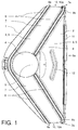
- Fig. 1 and 2 show a suction nozzle, also called floor nozzle, in a schematic bottom view.
- the suction nozzle has a housing 1 made of plastic, on which the bottom side a bottom plate 2 is formed. Below the bottom plate 2, a suction chamber 3 is formed, in which a suction channel 4 opens and which forms a suction mouth 5 as a bottom-side opening. How out Fig. 1 can be seen, the bottom plate 2 and the suction mouth 5 on a shape in the manner of an isosceles triangle, the base 6a in the pre-stroke represents the front of the suction nozzle.
- the suction channel 4 is fluid-tight with a provided on the top of the housing 1 connecting piece, not shown, connected.
- a handling pipe and / or a flexible hose can be connected in a flow-tight manner to a base housing of a vacuum cleaner, in which an electrically operated suction fan motor for establishing a suction air flow is arranged.
- an electrically operated suction fan motor for establishing a suction air flow is arranged.
- dirt and / or dust entrained by the suction air flow from the floor to be cleaned can be separated in a dust filter bag.
- the suction mouth 5 has a central suction mouth section 6 as well as two lateral suction mouth sections 7 flanking or enclosing the central suction mouth section 6.
- the lateral suction mouth sections 7 extend from the suction channel 4 substantially linearly toward each corner 7a of the isosceles triangle, so that the angle ⁇ between the longitudinal extension directions of the two lateral suction mouth sections 7 is 135 ° is.
- the lateral suction flow sections 8 are limited by inner and outer lateral flow sealing means 8.
- the outer lateral flow sealing means 8 extend from a respective corner 7a of the isosceles triangle along the respective leg and between the two legs, the suction channel 4 partially delimiting, part-circular in one another over ,
- outer lateral flow seal means 8 which are designed here as a bristle row.
- the inner lateral flow seal means 8 extend approximately parallel to the outer lateral flow seal means 8 away from the suction channel 4 in the direction of the corners 7a, so that on the suction channel 4 between the two inner lateral flow seal means 8, an air passage 9 is formed for the Saugluftströmung.
- the air passage 9 has a width of 37 mm, while the two lateral suction mouth sections 7 each have a width of 35 mm in the region of the suction channel 4.
- the two lateral suction mouth sections 7 extend from the suction channel 4 to opposite sides 9a of the suction nozzle and each have a lateral opening 10 at their head ends on the sides 9a.
- the lateral suction mouth sections 7 have a constant height of 22 mm, while the width of the lateral suction mouth sections 7 linearly from 35 mm at the suction channel 4 initially to 26 mm before a bend 9b the side suction mouth sections 7 and then reduced to 25 mm at the opening 10.
- lateral suction mouth sections 7 extend away from the suction channel 4 initially at an angle of 67.5 ° relative to the base 6a or the front side of the suction nozzle, causes the bend 9b that the openings 10 each extend perpendicular or approximately perpendicular to the base 6a and the front of the suction nozzle.
- the two lateral suction mouth sections 7 are each partially closed by a closing element 10a, through which a U-shaped window is formed as a lateral opening 10 of the lateral suction mouth section 7.
- the flat configured end element 10a also called choke wall, is integrally formed with the housing 1 and extends at a material thickness of 2.5 mm perpendicular to the bottom and the front of the suction nozzle of the housing 1 in the direction of the bottom, so that an opening width of the respective side suction mouth portion 7 between the bottom and the bottom facing the lower edge of the opening 10 of 7.6 mm is formed.
- the central suction mouth 6 has a shape like an isosceles triangle, wherein the two inner lateral flow seal means 8 fluidly define the central suction mouth 6 at the legs.
- the air passage 9 is arranged towards the suction channel 4, while opposite to the base 6a or the front side of the suction nozzle a front flow sealing means 11 is provided for at least partial sealing of the central suction mouth section 6.
- the front flow sealing means 11 is designed as a flexible sealing lip, so that coarse material can pass through the sealing lip.
- the coarse material that has arrived in the central suction mouth section 6 is detected by the suction air flow and sucked out through the suction channel 4.
- the front flow sealant 11 extends from the bottom plate 2 to the bottom, with a gap of approximately 50 mm being formed laterally between the front flow sealant 11 and the corners 7a of the suction nozzle, respectively. so
- the front flow-sealing means 11 designed as a sealing lip can pivot into the suction chamber 3 when coarse material is passed over, without touching the inner lateral flow-sealing means 8.
- an acoustic shielding means 12 is provided for further reducing the noise emission, which in the present case is provided in FIG Fig. 1 shown plan view, when integrally formed with the housing 1 V-shaped bar is designed, which is oriented from the bottom plate 2 toward the ground, but without touching the ground.
- the thus configured acoustic shielding means 12 is disposed in the central suction mouth portion 6 in the suction air flow direction between the suction passage 4 and the base 6a forming the front side of the suction nozzle.
- the distance between the front flow sealing means 11 and the acoustic shielding means 12 is 15 mm, while the distance between the acoustic shielding means 12 and the inner lateral flow sealing means 8 is 22 mm in each case.
- the means for acoustic shielding 12 may also be made of two approximately 5 cm long extending bristle strips, which are arranged at an angle of about 30 ° to each other offset to the bottom plate 2 that a direct acoustic emission from the suction channel 4 to the Front is reduced.
- the suction nozzle is characterized by a very efficient coarse material, which due to the means for acoustic shield 12 and due to the front flow sealant 11 only a small noise emission is recorded.
Landscapes
- Engineering & Computer Science (AREA)
- Mechanical Engineering (AREA)
- Nozzles For Electric Vacuum Cleaners (AREA)
Abstract
Description
- Die Erfindung betrifft eine Saugdüse für einen Staubsauger zum Aufsaugen von Schmutz und/oder Staub von einem Boden mittels einer Saugluftströmung mit einem Gehäuse, einem innerhalb des Gehäuses gebildeten Saugraum, einem in den Saugraum mündenden Saugkanal zum Führen der Saugluftströmung und einem als bodenseitige Öffnung des Saugraums ausgebildeten Saugmund.
- Saugdüsen, auch als Vorsatzgeräte, abgekürzt als Düsen oder in Abhängigkeit vom Einsatzzweck als Hartboden- oder Teppichdüsen bezeichnet, sind aus der Praxis bekannt und werden in der Regel zusammen mit einem Staubsauger zum Aufsaugen von Schmutz und/oder Staub von einem Boden verwendet. Staubsauger mit derartigen Saugdüsen verfügen regelmäßig über ein Grundgehäuse, in welchem ein elektrisch betriebener Sauggebläsemotor zum Aufbau einer Saugluftströmung angeordnet ist. Die Saugdüse wird typischerweise über einen flexiblen Saugschlauch und/oder ein Handhabungsrohr strömungsdicht mit dem Staubsauger verbunden. Bei Saugrobotern ist die Saugdüse im Allgemeinen in das Grundgehäuse selbst integriert. An der Saugdüse ist vielfach eine Borstenreihe oder dergleichen zum Lösen von Schmutz und/oder Staub von einem Boden vorgesehen. Der derart vom Boden abgelöste Staub und/oder Schmutz wird von der Saugluftströmung mitgerissen und zumeist in einem in dem Grundgehäuse angeordneten Staubsammelraum in einem Staubfilterbeutel abgesondert.
- Bei dem von dem Boden abzureinigenden Schmutz bzw. Staub wird in Anlehnung an die jeweilige Partikelgröße zwischen Grobgut und Feinstaub unterschieden. Aus dem Stand der Technik sind einerseits zur Aufnahme von Grobgut optimierte Saugdüsen bekannt, während wieder andere Saugdüsen für eine besonders gute Aufnahme von Feinstaub ausgelegt sind. Beispielsweise sind Hartbodendüsen oftmals nicht zum Aufsaugen von Grobgut ausgestaltet, während weitere Saugdüsen existieren, die manuell mit Hilfe eines Fußtasters zwischen der Aufnahme von Grobgut und Feinstaub umschaltbar sind. Durch Betätigung des Fußtasters wird oftmals ein Borstenstreifen aus der Saugdüse ausgefahren, durch den der Abstand der Saugdüse zum Boden vergrößert wird, so dass Grobgut besser aufgenommen bzw. abgesaugt werden kann. Letztendlich ist es jedoch so, dass die aus dem Stand der Technik bekannten Saugdüsen entweder nur einer der konkurrierenden und insofern entgegengesetzten Anforderungen genügen, also entweder zur Grobgut oder zur Feinstaubaufnahme prädestiniert sind, oder aber vom Bediener zwischen unterschiedlichen Betriebsmodi manuell umgeschaltet werden müssen.
- Ausgehend davon ist es eine Aufgabe der Erfindung, eine Saugdüse anzugeben, die zur Aufnahme von Schmutz und/oder Staub unterschiedlicher Partikelgröße universell einsetzbar ist und sich insbesondere durch eine besonders gute Aufnahme von Feinstaub auszeichnet. Darüber hinaus soll die Saugdüse die Aufnahme sowohl von Grobgut als auch von Feinstaub erlauben, ohne dass dazu ein Betriebsmodus der Saugdüse manuell umgeschaltet werden muss. Darüber hinaus ist es wünschenswert, dass eine derartige Saugdüse durch eine geringe Schiebekraft und/oder eine geringe Lärmemission gekennzeichnet ist.
- Die Lösung der Aufgabe erfolgt durch die Merkmale des unabhängigen Anspruchs. Vorteilhafte Ausgestaltungen sind in den Unteransprüchen angegeben.
- Demnach erfolgt die Lösung der Aufgabe durch eine Saugdüse für einen Staubsauger zum Aufsaugen von Schmutz und/oder Staub von einem Boden mittels einer Saugluftströmung mit einem Gehäuse, einem innerhalb des Gehäuses gebildeten Saugraum, einem in den Saugraum mündenden Saugkanal zum Führen der Saugluftströmung und einem als bodenseitige Öffnung des Saugraums ausgebildeten Saugmund, wobei der Saugmund einen zentralen Saugmundabschnitt und zwei den zentralen Saugmundabschnitt flankierende seitliche Saugmundabschnitte aufweist, und die seitlichen Saugmundabschnitte derart ausgebildet sind, dass sich die seitlichen Saugmundabschnitte von dem Saugkanal hin zu entgegengesetzten Seiten der Saugdüse in ihrem Querschnitt verjüngend weg erstrecken und an ihren Kopfenden jeweils durch ein Abschlusselement teilgeschlossen sind.
- Ein wesentlicher Punkt der Erfindung liegt in der Aufteilung des Saugmunds in den zentralen Saugmundabschnitt und die beiden seitlichen Saugmundabschnitte, so dass getrennte Bereiche für die Aufnahme von Feinstaub, insbesondere durch die seitlichen Saugmundabschnitte, und für Grobgut, insbesondere durch den zentralen Saugmundabschnitt, geschaffen werden. Durch die vorgeschlagene Ausgestaltung der sich in ihrem Querschnitt verjüngenden seitlichen Saugmundabschnitte, welche an ihren Kopfenden jeweils durch ein Abschlusselement teilgeschlossen sind, wird eine hohe Strömungsgeschwindigkeit bzw. ein hoher Volumenstrom in den seitlichen Saugmundabschnitten erreicht, wodurch im Vergleich zu aus dem Stand der Technik bekannten Ausgestaltungen eine wesentlich bessere Feinstaubaufnahme ermöglicht wird. Die durch die seitlichen Saugmundabschnitte und den zentralen Saugmundabschnitt hindurchführenden Saugluftströmungen treffen im Bereich des Saugkanals aufeinander, von wo die Saugluftströmung mit dem vom Boden aufgesaugten Schmutz bzw. Staub beispielsweise durch einen Anschlussstutzen aus der Saugdüse weggeführt wird.
- Der aufgrund der vorgeschlagenen Ausgestaltung in den seitlichen Saugmundabschnitten resultierende hohe Unterdruck lässt sich in vorteilhafter Weise bei einer vergleichsweise kleinen unterdruckbehafteten Fläche der Saugdüse realisieren. Entsprechend ist die vorgeschlagene Saugdüse durch eine geringe Schiebekraft gekennzeichnet. Da auch kein manuelles Umschalten verschiedener Betriebsmodi zum Aufsaugen von Feinstaub und Grobgut notwendig ist, erlaubt die Saugdüse ein besonders einfaches Arbeiten. Zudem zeichnet sich die Saugdüse in weiter vorteiliger Weise durch eine geringe Lärmemission aus. Im Ergebnis ermöglicht die vorgeschlagene Saugdüse durch die Ausgestaltung der seitlichen Saugmundabschnitte sowie der Aufteilung des Saugmunds in den zentralen Saugmundabschnitt und die beiden den zentralen Saugmundabschnitt vorzugsweise einrahmenden seitlichen Saugmundabschnitten eine besonders hohe Saugleistung sowohl bei der Aufnahme von Feinstaub als auch von Grobgut. Die vorliegend gewählte Terminologie zur Beschreibung der Anordnung der Teile der Saugdüse ist derart, dass von einer Lage und Ausrichtung der Saugdüse ausgegangen wird, wie sie auch im Betriebsfall beim Saugen eines Bodens vorliegt, indem die Saugdüse auf dem Boden aufgesetzt ist und über diesen bewegt wird.
- Nach einer bevorzugten Weiterbildung verjüngt sich der Querschnitt der seitlichen Saugmundabschnitte linear, stufenförmig und/oder in einer Kurvenform. Besonders bevorzugt sind die seitlichen Saugmundabschnitte derart ausgeführt, dass sich die Breite der seitlichen Saugmundabschnitte von ≥ 30 mm und ≤ 40 mm, vorzugsweise 35 mm an dem Saugkanal auf ≥ 20 mm und ≤ 30 mm, vorzugsweise 25 mm an den Seiten der Saugdüse vor dem Abschlusselement verjüngt, wobei die Höhe der seitlichen Saugmundabschnitte an dem Saugkanal sowie an den Seiten der Saugdüse vor dem Abschlusselement ≥ 20 mm und ≤ 30 mm, vorzugsweise 22 mm beträgt. Für eine optimale Feinstaubaufnahme hat sich experimentell als besonders vorteilhaft erwiesen, wenn sich die seitlichen Saugmundabschnitte jeweils von einer Breite von 33 mm an ihrer Mündung in den Saugkanal auf 27 mm in einem Bereich vor dem Abschlusselement linear verjüngen, während die Höhe des jeweiligen seitlichen Saugmundabschnitts konstant 22 mm beträgt.
- Für die Ausgestaltung des Abschlusselementes existieren verschiedene Möglichkeiten, wobei grundsätzlich bevorzugt ist, dass durch das Abschlusselement der Querschnitt des seitlichen Saugmundabschnitts verringert wird. Nach einer besonders bevorzugten Ausgestaltung ist vorgesehen, dass sich das Abschlusselement versprungartig von dem Gehäuse in Richtung Boden derart weg erstreckt, dass das Abschlusselement eine Öffnung des seitlichen Saugmundabschnitts an der Seite der Saugdüse mit einer Höhe von ≥ 6 mm und ≤ 10 mm, vorzugsweise 7,6 mm, und einer Breite von ≥ 20 mm und ≤ 30 mm oder ≤ 30 mm, vorzugsweise 25 mm, ausbildet. Das Abschlusselement ist bevorzugt als ein in Unteransicht beurteilt seitliches, U-förmiges Fenster ausgebildet. In Seitenansicht beurteilt ist das Fenster bevorzugt wenigstens teilweise durch das Gehäuse und seitliche, nachfolgend beschriebene Strömungsdichtungsmittel begrenzt. Besonders bevorzugt ist das Abschlusselement einstückig mit dem Gehäuse ausgestaltet, beispielsweise aus einem Kunststoff gespritzt, und weist eine Dicke von ≥ 2 mm und ≤ 4 mm, vorzugsweise 2,5 mm auf. Das Abschlusselement erstreckt sich bevorzugt in vertikaler Richtung weg von dem Gehäuse.
- In einer weiteren besonders vorteilhaften Ausgestaltung weisen die seitlichen Saugmundabschnitte an ihren Kopfenden an den Seiten der Saugdüse jeweils eine Abwinklung auf, wobei die Abwinklung vorzugsweise derart ausbildet ist, dass durch die Abwinklung die Breite der seitlichen Saugmundabschnitte reduziert wird und/oder sich die durch die Abschlusselemente an den Seiten der Saugdüse ausgebildeten Öffnungen der seitlichen Saugmundabschnitte senkrecht zu einer vorderen Öffnung des zentralen Saugmundabschnitts erstrecken. Bevorzugt ist die Abwinklung derart ausgestaltet, dass durch die Abwinklung eine Verringerung der Breite des seitlichen Saugmundabschnitts um 2 mm, 5 mm oder 10 mm in Richtung der Seite der Saugdüse bewirkt wird. Bezug nehmend auf die bereits zuvor angesprochene Ausgestaltung lässt sich eine besonders gute Feinstaubaufnahme dann erreichen, wenn sich die seitlichen Saugmundabschnitte jeweils von einer Breite von 33 mm an ihrer Mündung in den Saugkanal linear bis auf eine Breite von 27 mm unmittelbar vor der Abwinklung verjüngen, woraufhin sich eine weitere durch die Abwinklung bedingte Verjüngung der Breite bis auf 25 mm an den jeweiligen Seiten anschließt.
- Nach einer bevorzugten Weiterbildung weist der Saugmund und/oder der zentrale Saugmundabschnitt eine Form nach Art eines gleichschenkligen Dreiecks auf, wobei bevorzugt der Saugkanal im Bereich der Spitze zwischen den Schenkeln des Dreiecks in den derart gebildeten Saugraum mündet, sich der zentrale Saugmundabschnitt von dem Saugkanal bis zu der Basis des gleichschenkligen Dreiecks erstreckt und sich die seitlichen Saugmundabschnitte von dem Saugkanal entlang der jeweiligen Schenkel des gleichschenkligen Dreiecks bis zu den der Spitze entgegengesetzt angeordneten Ecken des gleichschenkligen Dreiecks erstrecken. Durch die vorgeschlagene Ausgestaltung ist ein durch den zentralen Saugmundabschnitt ausgebildeter Grobgutbereich im Vorhub der Saugdüse im Wesentlichen vor dem durch die seitlichen Saugmundabschnitte ausgebildeten Feinstaubbereich angeordnet. Vorzugsweise grenzen dabei die seitlichen Saugmundabschnitte an den der Spitze entgegengesetzt angeordneten Ecken des gleichschenkligen Dreiecks an den zentralen Saugmundabschnitt an. Derart wird die Feinstaubaufnahme in vorteilhafter Weise zumindest in Eckbereichen der Saugdüse und bis hin zu der Vorderseite der Saugdüse ermöglicht.
- Nach einer weiteren bevorzugten Ausgestaltung erstrecken sich die beiden seitlichen Saugmundabschnitte von dem Saugkanal jeweils zu einer Seite der Saugdüse derart weg, dass für den Winkel α zwischen den Längserstreckungsrichtungen der beiden seitlichen Saugmundabschnitte gilt 45° ≤ α ≤ 160°, vorzugsweise 90° ≤ α ≤ 135°, ganz besonders bevorzugt α ≤ 135°, oder sich die beiden seitlichen Saugmundabschnitte von dem Saugkanal in einen Kurvenverlauf voneinander weg erstrecken. Sofern sich die beiden seitlichen Saugmundabschnitte zwischen dem Saugkanal und den Seiten der Saugdüse linear oder annähernd linear erstrecken, beispielsweise entlang der Schenkel eines nach Art eines gleichschenkligen Dreiecks ausgestalteten Saugmunds, dann weist der zentrale Saugmundabschnitt bevorzugt eine dreieckartige Form nach Art eines gleichschenkligen Dreiecks auf, dessen Basis in Richtung der Vorderseite der Saugdüse orientiert ist.
- Nach einer besonders bevorzugten Weiterbildung sind die seitlichen Saugmundabschnitte jeweils durch sich von dem Saugkanal bis hin zu den Seiten der Saugdüse erstreckende innere und äußere seitliche Strömungsdichtungsmittel derart begrenzt, dass der zentrale Saugmundabschnitt durch die inneren seitlichen Strömungsdichtungsmittel der jeweiligen seitlichen Saugmundabschnitte begrenzt ist. Die inneren und äußeren Strömungsdichtungsmittel können grundsätzlich beliebig zum Abdichten der Saugluftströmung ausgestaltet sein, wobei jedoch bevorzugt die seitlichen Strömungsdichtungsmittel als Borstenstreifen, als ein- oder mehrreihige Anordnung von Borstenbüscheln, als Dichtungslippe und/oder als Kombination dessen ausgestaltet sind.
- Die Borsten bzw. die Dichtungslippen erstrecken sich bevorzugt von dem Gehäuse senkrecht weg in Richtung Boden und sind flexibel ausgestaltet, so dass beim Verschieben der Saugdüse in die übliche Verschieberichtung auf dem Boden befindliches Grobgut oder Feinstaub unter den Borsten bzw. den Dichtungslippen hindurch in den zentralen Saugmundabschnitt und/oder die seitlichen Saugmundabschnitte gelangen kann. Die beiden inneren Strömungsdichtungsmittel begrenzen bevorzugt den Durchgang der Saugluftströmung zwischen dem Saugkanal und dem zentralen Saugmundabschnitt, wobei die Öffnungsweite zwischen den beiden inneren Strömungsdichtungsmitteln bevorzugt 25 mm, 30 mm, 32 mm, 37 mm, 40 mm oder 45 mm beträgt, damit ein Anteil von ≥ 40 % und ≤ 65 % der Saugluftströmung durch den zentralen Saugmundabschnitt strömt.
- Besonders bevorzugt erstrecken sich die seitlichen Strömungsdichtungsmittel von dem Saugkanal nahezu linear bis hin zu den Seiten der Saugdüse. Die äußeren seitlichen Strömungsdichtungsmittel sind bevorzugt an einem Rand der Saugdüse angeordnet und erstrecken sich derart bevorzugt entlang des gesamten Randes. Im Bereich des Saugkanals sind die beiden äußeren Strömungsdichtungsmittel bevorzugt einteilig ausgestaltet und gehen ganz besonders bevorzugt kurvenförmig ineinander über. Der Saugkanal weist bevorzugt einen runden oder ovalartigen Querschnitt auf, welcher im Mündungsbereich wenigstens teilweise durch die äußeren seitlichen Strömungsdichtungsmittel begrenzt ist. An den Seiten der Saugdüse, bzw. im Falle eines Saugmunds nach Art eines gleichschenkligen Dreiecks an den Ecken des Dreiecks, sind die seitlichen Saugmundabschnitte bevorzugt geöffnet, beispielsweise durch das U-förmige seitliche Fenster, durch das Feinstaub in den jeweiligen seitlichen Saugmundabschnitt einströmen kann.
- Nach einer bevorzugten Weiterbildung weist der Saugmund einen weiteren zentralen Saugmundabschnitt und zwei weitere den weiteren zentralen Saugmundabschnitt flankierende seitliche Saugmundabschnitte auf, wobei sich der zentrale Saugmundabschnitt und der weitere zentrale Saugmundabschnitt von dem Saugkanal in entgegengesetzten Richtungen derart weg erstrecken, dass die zwei seitlichen Saugmundabschnitte und die zwei weiteren seitlichen Saugmundabschnitte eine x-förmige Anordnung ausbilden. Eine derart ausgestaltete Saugdüse kann sowohl im Vorhub als auch im Rückhub Grobgut aufnehmen. Bevorzugt ist die Saugdüse im Vorhub und im Rückhub symmetrisch, insbesondere spiegelsymmetrisch ausgestaltet. Weiter bevorzugt stellt der Saugkanal in Draufsicht den Mittelpunkt dieser Ausgestaltung dar, von dem sich der zentrale Saugmundabschnitt mit den beiden seitlichen Saugmundabschnitten und insbesondere spiegelsymmetrisch gegenüberliegend der weitere zentrale Saugmundabschnitt mit den weiteren seitlichen Saugmundabschnitten weg erstrecken. Bei dieser Ausgestaltung kann ein Bediener, anstelle eine aus dem Stand der Technik bekannte Saugdüse manuell um 180° zu drehen, die Saugdüse schlichtweg vor und zurück bewegen, um derart sowohl im Vorhub als auch im Rückhub Grobgut aufzunehmen.
- Nachfolgend wird die Erfindung unter Bezugnahme auf die anliegende Zeichnung anhand einer bevorzugten Ausführungsform näher erläutert.
- Es zeigen:
- Fig. 1
- eine Saugdüse gemäß einer bevorzugten Ausführungsform der Erfindung in schematischer Unteransicht der Saugdüse, und
- Fig. 2
- die Saugdüse nach
Fig. 1 in einer perspektivischen Ansicht. -
Fig. 1 und2 zeigen eine Saugdüse, auch Bodendüse genannt, in einer schematischen Unteransicht. Die Saugdüse weist ein Gehäuse 1 aus Kunststoff auf, an welchem bodenseitig eine Bodenplatte 2 ausgebildet ist. Unterhalb der Bodenplatte 2 ist ein Saugraum 3 ausgebildet, in welchem ein Saugkanal 4 mündet und welche als bodenseitige Öffnung einen Saugmund 5 ausbildet. Wie ausFig. 1 zu erkennen ist, weisen die Bodenplatte 2 sowie der Saugmund 5 eine Form nach Art eines gleichschenkligen Dreiecks auf, dessen Basis 6a in Vorhubrichtung die Vorderseite der Saugdüse darstellt. - Der Saugkanal 4 ist strömungsdicht mit einem an der Oberseite des Gehäuses 1 vorgesehenen Anschlussstutzen, nicht gezeigt, verbunden. An den Anschlussstutzen lässt sich ein Handhabungsrohr und/oder ein flexibler Schlauch strömungsdicht mit einem Grundgehäuse eines Staubsaugers verbinden, in welchem ein elektrisch betriebener Sauggebläsemotor zum Aufbauen einer Saugluftströmung angeordnet ist. In einem in dem Grundgehäuse angeordneten Staubsammelraum ist von der Saugluftströmung von dem zu reinigenden Boden mitgerissener Schmutz und/oder Staub in einem Staubfilterbeutel abtrennbar.
- Der Saugmund 5 weist einen zentralen Saugmundabschnitt 6 sowie zwei den zentralen Saugmundabschnitt 6 flankierende bzw. einfassende seitliche Saugmundabschnitte 7 auf. Die seitlichen Saugmundabschnitte 7 erstrecken sich von dem Saugkanal 4 im Wesentlichen linear hin zu jeweils einer Ecke 7a des gleichschenkligen Dreiecks, so dass der Winkel α zwischen den Längserstreckungsrichtungen der beiden seitlichen Saugmundabschnitte 7 135° beträgt. Strömungstechnisch begrenzt sind die seitlichen Saugmundabschnitte 7 durch innere und äußere seitliche Strömungsdichtungsmittel 8. Die äußeren seitlichen Strömungsdichtungsmittel 8 erstrecken sich von einer jeweiligen Ecke 7a des gleichschenkligen Dreiecks entlang des jeweiligen Schenkels und gehen zwischen den beiden Schenkeln, den Saugkanal 4 teilweise begrenzend, teilkreisförmig ineinander über.
- Entsprechend ist die komplette Rückseite der Saugdüse durch äußere seitliche Strömungsdichtungsmittel 8 begrenzt, welche vorliegend als Borstenreihe ausgestaltet sind. Die inneren seitlichen Strömungsdichtungsmittel 8 erstrecken sich annähernd parallel zu den äußeren seitlichen Strömungsdichtungsmitteln 8 derart von dem Saugkanal 4 weg in Richtung der Ecken 7a, so dass an dem Saugkanal 4 zwischen den beiden inneren seitlichen Strömungsdichtungsmitteln 8 ein Luftdurchgang 9 für die Saugluftströmung ausgebildet ist. Der Luftdurchgang 9 weist vorliegend eine Breite von 37 mm auf, während die beiden seitlichen Saugmundabschnitte 7 im Bereich des Saugkanals 4 jeweils eine Breite von 35 mm aufweisen. Durch die vorgenannte Dimensionierung wird erreicht, dass ein Anteil von 45 % der Saugluftströmung von dem Saugkanal 4 durch den zentralen Saugmundabschnitt 6 strömt, während sich der verbleibende Anteil von 55 % gleichmäßig auf die beiden seitlichen Saugmundabschnitte 7 aufteilt.
- Die beiden seitlichen Saugmundabschnitte 7 erstrecken sich von dem Saugkanal 4 hin zu entgegengesetzten Seiten 9a der Saugdüse und weisen an ihren Kopfenden an den Seiten 9a jeweils eine seitliche Öffnung 10 auf. Entlang ihrer Erstreckung von dem Saugkanal 4 bis hin zu den Seiten 9a weisen die seitlichen Saugmundabschnitte 7 eine konstante Höhe von 22 mm auf, während sich die Breite der seitlichen Saugmundabschnitte 7 linear von 35 mm an dem Saugkanal 4 zunächst auf 26 mm vor einer Abwinklung 9b der seitlichen Saugmundabschnitte 7 und dann auf 25 mm an der Öffnung 10 reduziert. Während sich die seitlichen Saugmundabschnitte 7 von dem Saugkanal 4 zunächst in einem Winkel von 67,5° bezogen auf die Basis 6a bzw. die Vorderseite der Saugdüse weg erstrecken, bewirkt die Abwinklung 9b, dass sich die Öffnungen 10 jeweils senkrecht oder annährend senkrecht zu der Basis 6a bzw. der Vorderseite der Saugdüse erstrecken.
- An den Öffnungen 10 sind die beiden seitlichen Saugmundabschnitte 7 jeweils durch ein Abschlusselement 10a teilgeschlossen, durch welches ein U-förmiges Fenster als seitliche Öffnung 10 des seitlichen Saugmundabschnitts 7 ausgebildet wird. Das flächig ausgestaltete Abschlusselement 10a, auch Drosselwand genannt, ist einstückig mit dem Gehäuse 1 ausgestaltet und erstreckt sich bei einer Materialdicke von 2,5 mm senkrecht zum Boden sowie zur Vorderseite der Saugdüse von dem Gehäuse 1 in Richtung Boden, so dass eine Öffnungsweite des jeweiligen seitlichen Saugmundabschnitts 7 zwischen dem Boden und der dem Boden zugewandten Unterkante der Öffnung 10 von 7,6 mm ausgebildet wird.
- Ebenso wie der Saugmund 5 sowie die Bodenplatte 2 weist der zentrale Saugmundabschnitt 6 eine Form nach Art eines gleichschenkligen Dreiecks auf, wobei die beiden inneren seitlichen Strömungsdichtungsmittel 8 den zentralen Saugmundabschnitt 6 an den Schenkeln strömungsdicht begrenzen. Wie bereits erwähnt, ist an der Spitze des zentralen Saugmundabschnitts der Luftdurchgang 9 hin zum Saugkanal 4 angeordnet, während gegenüberliegend an der Basis 6a bzw. der Vorderseite der Saugdüse ein vorderes Strömungsdichtungsmittel 11 zur wenigstens teilweisen Abdichtung des zentralen Saugmundabschnitts 6 vorgesehen ist.
- Das vordere Strömungsdichtungsmittel 11 ist als flexible Dichtungslippe ausgestaltet, so dass Grobgut die Dichtungslippe passieren kann. Das im zentralen Saugmundabschnitt 6 angelangte Grobgut wird von der Saugluftströmung erfasst und durch den Saugkanal 4 hindurch abgesaugt. Das vordere Strömungsdichtungsmittel 11 reicht von der Bodenplatte 2 bis auf den Boden, wobei jeweils seitlich zwischen dem vorderen Strömungsdichtungsmittel 11 und den Ecken 7a der Saugdüse ein Spalt von annähernd 50 mm ausgebildet ist. Derart kann das als Dichtungslippe ausgestaltete vordere Strömungsdichtungsmittel 11 beim Überfahren von Grobgut in den Saugraum 3 hinein verschwenken, ohne dabei die inneren seitlichen Strömungsdichtungsmittel 8 zu berühren.
- Während durch das vordere Strömungsdichtungsmittel 11 bereits der Austritt von durch die Saugluftströmung bewirkter Lärmemission reduziert ist, ist zur weiteren Reduzierung der Lärmemission ein Mittel zur akustischen Abschirmung 12 vorgesehen, welches vorliegend, in der in
Fig. 1 gezeigten Draufsicht, als einstückig mit dem Gehäuse 1 ausgeformte V-förmige Leiste ausgestaltet ist, die von der Bodenplatte 2 hin zum Boden orientiert ist, ohne dabei jedoch den Boden zu berühren. Das derart ausgestaltete Mittel zur akustischen Abschirmung 12 ist in dem zentralen Saugmundabschnitt 6 in Saugluftströmungsrichtung zwischen dem Saugkanal 4 und der die Vorderseite der Saugdüse bildenden Basis 6a angeordnet. - Der Abstand zwischen dem vorderen Strömungsdichtungsmittel 11 und dem Mittel zur akustischen Abschirmung 12 beträgt 15 mm, während der Abstand zwischen dem Mittel zur akustischen Abschirmung 12 und den inneren seitlichen Strömungsdichtungsmitteln 8 jeweils 22 mm beträgt. Alternativ kann das Mittel zur akustischen Abschirmung 12 auch aus zwei sich etwa 5 cm lang erstreckenden Borstenstreifen ausgeführt sein, die in einem Winkel von etwa 30° zueinander versetzt derart an der Bodenplatte 2 angeordnet sind, dass eine direkte Schallemission von dem Saugkanal 4 hin zu der Vorderseite vermindert ist.
- Durch die vorgeschlagene Ausgestaltung der sich in ihrem Querschnitt verjüngenden seitlichen Saugmundabschnitte 7, welche an beiden Seiten 9a jeweils durch ein Abschlusselement 10a teilgeschlossen sind, wird eine hohe Strömungsgeschwindigkeit bzw. ein hoher Volumenstrom in den seitlichen Saugmundabschnitten 7 erreicht, wodurch im Vergleich zu aus dem Stand der Technik bekannten Ausgestaltungen eine wesentlich bessere Feinstaubaufnahme insbesondere aus Fugen und Ritzen ermöglicht wird. Da der Saugmund 5 eine vergleichsweise kleine unterdruckbehaftete Fläche aufweist, ist die zuvor beschriebene Ausgestaltung durch eine geringe Schiebekraft gekennzeichnet. Da andererseits der zentrale Saugmundabschnitt 6 demgegenüber offener gestaltet ist, zeichnet sich die Saugdüse zudem durch eine sehr effiziente Grobgutaufnahme aus, wobei aufgrund des Mittels zur akustischen Abschirmung 12 sowie aufgrund des vorderen Strömungsdichtungsmittels 11 eine nur geringe Lärmemission zu verzeichnen ist.
-
- Gehäuse 1
- Bodenplatte 2
- Saugraum 3
- Saugkanal 4
- Saugmund 5
- Zentraler Saugmundabschnitt 6
- Basis 6a
- Seitlicher Saugmundabschnitt 7
- Ecke 7a
- Strömungsdichtungsmittel 8
- Luftdurchgang 9
- Seite 9a
- Abwinklung 9b
- Öffnung 10
- Abschlusselement 10a
- Vorderes Strömungsdichtungsmittel 11
- Mittel zur akustischen Abschirmung 12
- Winkel α
Claims (10)
- Saugdüse für einen Staubsauger zum Aufsaugen von Schmutz und/oder Staub von einem Boden mittels einer Saugluftströmung mit einem Gehäuse (1), einem innerhalb des Gehäuses (1) gebildeten Saugraum (3), einem in den Saugraum (3) mündenden Saugkanal (4) zum Führen der Saugluftströmung und einem als bodenseitige Öffnung des Saugraums (3) ausgebildeten Saugmund (5), wobei
der Saugmund (5) einen zentralen Saugmundabschnitt (6) und zwei den zentralen Saugmundabschnitt (6) flankierende seitliche Saugmundabschnitte (7) aufweist, und
die seitlichen Saugmundabschnitte (7) derart ausgebildet sind, dass sich die seitlichen Saugmundabschnitte (7) von dem Saugkanal (4) hin zu entgegengesetzten Seiten (9a) der Saugdüse in ihrem Querschnitt verjüngend weg erstrecken und an ihren Kopfenden jeweils durch ein Abschlusselement (10a) teilgeschlossen sind. - Saugdüse nach dem vorhergehenden Anspruch, wobei sich der Querschnitt der seitlichen Saugmundabschnitte (7) linear, stufenförmig und/oder in einer Kurvenform verjüngt.
- Saugdüse nach einem der vorhergehenden Ansprüche, wobei die seitlichen Saugmundabschnitte (7) derart ausgeführt sind, dass sich die Breite der seitlichen Saugmundabschnitte (7) von ≥ 30 mm und ≤ 40 mm, vorzugsweise 33 mm an dem Saugkanal (4) auf ≥ 20 mm und ≤ 30 mm, vorzugsweise 27 mm an den Seiten (9a) der Saugdüse vor dem Abschlusselement (10a) verjüngt, wobei die Höhe der seitlichen Saugmundabschnitte (7) an dem Saugkanal (4) sowie an den Seiten (9a) der Saugdüse vor dem Abschlusselement (10a) ≥ 20 mm und ≤ 30 mm, vorzugsweise 22 mm beträgt.
- Saugdüse nach einem der vorhergehenden Ansprüche, wobei sich das Abschlusselement (10a) versprungartig von dem Gehäuse in Richtung Boden derart weg erstreckt, dass das Abschlusselement (10a) eine Öffnung (10) des seitlichen Saugmundabschnitts (7) an der Seite (9a) der Saugdüse mit einer Höhe von ≥ 6 mm und ≤ 10 mm, vorzugsweise 7,6 mm und einer Breite von ≥ 20 mm und ≤ 30 mm, vorzugsweise 25 mm ausbildet.
- Saugdüse nach einem der vorhergehenden Ansprüche, wobei das Abschlusselement (10a) einstückig mit dem Gehäuse (1) ausgestaltet ist und eine Dicke von ≥ 2 mm und ≤ 4 mm, vorzugsweise 2,5 mm aufweist.
- Saugdüse nach einem der vorhergehenden Ansprüche, wobei die seitlichen Saugmundabschnitte (7) an den Seiten (9a) der Saugdüse eine Abwinklung (9b) aufweisen und die Abwinklung (9b) vorzugsweise derart ausbildet ist, dass durch die Abwinklung (9b) die Breite der seitlichen Saugmundabschnitte (7) reduziert wird und/oder sich die durch die Abschlusselemente (10a) an den Seiten (9a) der Saugdüse ausgebildeten Öffnungen (10) der seitlichen Saugmundabschnitte (7) senkrecht zu einer vorderen Öffnung des zentralen Saugmundabschnitts (7) erstrecken.
- Saugdüse nach einem der vorhergehenden Ansprüche, wobei der Saugmund (5) eine Form nach Art eines gleichschenkligen Dreiecks aufweist, bevorzugt der Saugkanal (4) im Bereich der Spitze zwischen den Schenkeln des Dreiecks in den derart gebildeten Saugraum (3) mündet, sich der zentrale Saugmundabschnitt (6) von dem Saugkanal (4) bis zu der Basis (6a) des gleichschenkligen Dreiecks erstreckt und sich die seitlichen Saugmundabschnitte (7) von dem Saugkanal (4) entlang der jeweiligen Schenkel des gleichschenkligen Dreiecks bis hin zu den der Spitze entgegengesetzt angeordneten Ecken (7a) des gleichschenkligen Dreiecks erstrecken.
- Saugdüse nach einem der vorhergehenden Ansprüche, wobei sich die beiden seitlichen Saugmundabschnitte (7) von dem Saugkanal (4) jeweils zu einer Seite (9a) der Saugdüse derart weg erstrecken, dass für den Winkel α zwischen den Längserstreckungsrichtungen der beiden seitlichen Saugmundabschnitte (7) gilt 45° ≤ α ≤ 160°, vorzugsweise 90° ≤ α ≤ 135°, ganz besonders bevorzugt α ≤ 135°, oder sich die beiden seitlichen Saugmundabschnitte (6) von dem Saugkanal (4) in einen Kurvenverlauf voneinander weg erstrecken.
- Saugdüse nach einem der vorhergehenden Ansprüche, wobei die seitlichen Saugmundabschnitte (7) jeweils durch sich von dem Saugkanal (4) bis hin zu den Seiten (9a) der Saugdüse erstreckende innere und äußere seitliche Strömungsdichtungsmittel (8) begrenzt sind, so dass der zentrale Saugmundabschnitt (6) durch die inneren seitlichen Strömungsdichtungsmittel (8) der jeweiligen seitlichen Saugmundabschnitte (7) begrenzt ist.
- Saugdüse nach einem der vorhergehenden Ansprüche, wobei der Saugmund (5) einen weiteren zentralen Saugmundabschnitt und zwei den weiteren zentralen Saugmundabschnitt flankierende weitere seitliche Saugmundabschnitte aufweist, und sich der zentrale Saugmundabschnitt (6) und der weitere zentrale Saugmundabschnitt von dem Saugkanal (4) in entgegengesetzten Richtungen derart weg erstrecken, dass die zwei seitlichen Saugmundabschnitte (7) und die zwei weiteren seitliche Saugmundabschnitte eine x-förmige Anordnung ausbilden.
Applications Claiming Priority (1)
| Application Number | Priority Date | Filing Date | Title |
|---|---|---|---|
| DE102015108052.4A DE102015108052B4 (de) | 2015-05-21 | 2015-05-21 | Saugdüse zur Aufnahme von Grobgut und Feinstaub |
Publications (2)
| Publication Number | Publication Date |
|---|---|
| EP3095367A1 true EP3095367A1 (de) | 2016-11-23 |
| EP3095367B1 EP3095367B1 (de) | 2020-08-05 |
Family
ID=55919697
Family Applications (1)
| Application Number | Title | Priority Date | Filing Date |
|---|---|---|---|
| EP16168559.9A Active EP3095367B1 (de) | 2015-05-21 | 2016-05-06 | Saugdüse zur aufnahme von grobgut und feinstaub |
Country Status (6)
| Country | Link |
|---|---|
| EP (1) | EP3095367B1 (de) |
| JP (1) | JP2016214874A (de) |
| CN (1) | CN106166044A (de) |
| DE (1) | DE102015108052B4 (de) |
| ES (1) | ES2814125T3 (de) |
| TW (1) | TWI626033B (de) |
Cited By (2)
| Publication number | Priority date | Publication date | Assignee | Title |
|---|---|---|---|---|
| EP3378369A1 (de) * | 2017-03-20 | 2018-09-26 | Hako GmbH | Saugfuss für eine bodenreinigungsmaschine |
| US11937762B2 (en) | 2019-06-26 | 2024-03-26 | Milwaukee Electric Tool Corporation | Vacuum tools |
Families Citing this family (2)
| Publication number | Priority date | Publication date | Assignee | Title |
|---|---|---|---|---|
| CN106889945A (zh) * | 2017-03-16 | 2017-06-27 | 马涛 | 吸尘器吸嘴 |
| GB2571534B (en) * | 2018-02-28 | 2020-09-16 | Dyson Technology Ltd | A cleaner head |
Citations (8)
| Publication number | Priority date | Publication date | Assignee | Title |
|---|---|---|---|---|
| US3117338A (en) * | 1956-06-11 | 1964-01-14 | Filtex Corp | Suction nozzle |
| WO2002026097A1 (en) * | 2000-09-28 | 2002-04-04 | Dyson Limited | A floor tool |
| WO2002039865A2 (en) * | 2000-11-16 | 2002-05-23 | Koninklijke Philips Electronics N.V. | Suction attachment for a vacuum cleaner |
| DE10105371A1 (de) * | 2001-02-06 | 2002-08-14 | Wessel Werk Gmbh | Saugkopf für Haushalts-Bodenstaubsauger |
| EP1488728A1 (de) * | 2003-06-20 | 2004-12-22 | Seb S.A. | Staubsaugerdüse |
| US20100319159A1 (en) * | 2009-06-17 | 2010-12-23 | Dyson Technology Limited | Tool for a surface treating appliance |
| US20120000033A1 (en) * | 2009-03-13 | 2012-01-05 | G. B. D. Corp. | Surface cleaning apparatus |
| DE102012010075B3 (de) * | 2012-05-23 | 2013-09-26 | Regina Köster | Bodenreinigungselement und zugehöriger Staubsauger |
Family Cites Families (10)
| Publication number | Priority date | Publication date | Assignee | Title |
|---|---|---|---|---|
| SE448417B (sv) * | 1979-05-09 | 1987-02-23 | Schmidt Alfred Gmbh | Anordning for upptagning av sopor |
| FR2547494B1 (fr) * | 1983-06-20 | 1987-02-20 | Olivier Ets Georges | Suceur d'aspirateur perfectionne pour le nettoyage des sols au plus pres des plinthes, meubles ou autres |
| JPH06304099A (ja) * | 1993-04-26 | 1994-11-01 | Biaburu:Kk | 電気掃除機の寝具用吸込具 |
| CN1668238B (zh) * | 2002-01-25 | 2010-05-26 | 詹姆斯·R·奥尔顿 | 具有边缘抽吸管的真空吸尘器吸嘴组件 |
| KR100746080B1 (ko) * | 2005-12-06 | 2007-08-06 | 엘지전자 주식회사 | 청소기 및 그 사용방법 |
| KR101211497B1 (ko) * | 2006-01-13 | 2012-12-12 | 삼성전자주식회사 | 진공청소기 |
| DE102008029687A1 (de) * | 2007-07-09 | 2009-01-15 | Vorwerk & Co. Interholding Gmbh | Kombination einer Staubsaugerdüse mit einem Wischtuch, sowie Wischtuch und Verfahren zum Feuchtreinigen von Fußböden |
| US9173536B2 (en) * | 2011-08-23 | 2015-11-03 | Koninklijke Philips N.V. | Cleaning device for cleaning a surface comprising a brush and a squeegee element |
| JP5872339B2 (ja) * | 2012-03-15 | 2016-03-01 | 株式会社東芝 | 電気掃除機およびその吸込口体 |
| KR101432705B1 (ko) * | 2012-12-28 | 2014-09-23 | 주식회사 한경희생활과학 | 진공 청소기용 헤드 어셈블리 |
-
2015
- 2015-05-21 DE DE102015108052.4A patent/DE102015108052B4/de active Active
-
2016
- 2016-05-06 TW TW105114175A patent/TWI626033B/zh not_active IP Right Cessation
- 2016-05-06 EP EP16168559.9A patent/EP3095367B1/de active Active
- 2016-05-06 ES ES16168559T patent/ES2814125T3/es active Active
- 2016-05-20 JP JP2016101527A patent/JP2016214874A/ja active Pending
- 2016-05-20 CN CN201610339860.7A patent/CN106166044A/zh active Pending
Patent Citations (8)
| Publication number | Priority date | Publication date | Assignee | Title |
|---|---|---|---|---|
| US3117338A (en) * | 1956-06-11 | 1964-01-14 | Filtex Corp | Suction nozzle |
| WO2002026097A1 (en) * | 2000-09-28 | 2002-04-04 | Dyson Limited | A floor tool |
| WO2002039865A2 (en) * | 2000-11-16 | 2002-05-23 | Koninklijke Philips Electronics N.V. | Suction attachment for a vacuum cleaner |
| DE10105371A1 (de) * | 2001-02-06 | 2002-08-14 | Wessel Werk Gmbh | Saugkopf für Haushalts-Bodenstaubsauger |
| EP1488728A1 (de) * | 2003-06-20 | 2004-12-22 | Seb S.A. | Staubsaugerdüse |
| US20120000033A1 (en) * | 2009-03-13 | 2012-01-05 | G. B. D. Corp. | Surface cleaning apparatus |
| US20100319159A1 (en) * | 2009-06-17 | 2010-12-23 | Dyson Technology Limited | Tool for a surface treating appliance |
| DE102012010075B3 (de) * | 2012-05-23 | 2013-09-26 | Regina Köster | Bodenreinigungselement und zugehöriger Staubsauger |
Cited By (5)
| Publication number | Priority date | Publication date | Assignee | Title |
|---|---|---|---|---|
| EP3378369A1 (de) * | 2017-03-20 | 2018-09-26 | Hako GmbH | Saugfuss für eine bodenreinigungsmaschine |
| US11937762B2 (en) | 2019-06-26 | 2024-03-26 | Milwaukee Electric Tool Corporation | Vacuum tools |
| US12527449B2 (en) | 2019-06-26 | 2026-01-20 | Milwaukee Electric Tool Corporation | Vacuum tools |
| US12527450B2 (en) | 2019-06-26 | 2026-01-20 | Milwaukee Electric Tool Corporation | Vacuum tools |
| US12557953B2 (en) | 2019-06-26 | 2026-02-24 | Milwaukee Electric Tool Corporation | Vacuum tools |
Also Published As
| Publication number | Publication date |
|---|---|
| ES2814125T3 (es) | 2021-03-26 |
| CN106166044A (zh) | 2016-11-30 |
| EP3095367B1 (de) | 2020-08-05 |
| DE102015108052B4 (de) | 2020-02-13 |
| DE102015108052A1 (de) | 2016-11-24 |
| JP2016214874A (ja) | 2016-12-22 |
| TWI626033B (zh) | 2018-06-11 |
| TW201700052A (zh) | 2017-01-01 |
Similar Documents
| Publication | Publication Date | Title |
|---|---|---|
| EP3095368B1 (de) | Hartbodendüse für grobgut und feinstaubaufnahme | |
| EP2939582B1 (de) | Staubsaugerdüse | |
| EP3310233B1 (de) | Saugdüse für einen staubsauger | |
| EP2875765B1 (de) | Saugdüse für einen Staubsauger | |
| EP3095367B1 (de) | Saugdüse zur aufnahme von grobgut und feinstaub | |
| EP3095369B1 (de) | Saugdüse zur aufnahme von grobgut und feinstaub | |
| DE102014111702B4 (de) | Elektroteppichbürste zum Reinigen eines Untergrunds | |
| EP2937029B1 (de) | Saugdüse zum saugen von glattböden, insbesondere von gefliesten bodenflächen | |
| DE102014117418A1 (de) | Bodendüse für ein Bodenpflegegerät und Verfahren zum Herstellen einer Bodendüse für ein Bodenpflegegerät | |
| DE102012010075B3 (de) | Bodenreinigungselement und zugehöriger Staubsauger | |
| EP3050475B1 (de) | Saugdüse zum saugen von hartbodenflächen | |
| EP1595485A1 (de) | Bodendüse für Staubsauger | |
| DE102018120544B4 (de) | Saugdüse für einen Staubsauger | |
| DE102017118487A1 (de) | Saugdüse für ein ein Sauggebläse aufweisendes Reinigungsgerät | |
| DE102004005144A1 (de) | Bodendüse für einen Staubsauger | |
| DE102014116280A1 (de) | Saugdüse | |
| DE102015105228A1 (de) | Vorrichtung für ein ein saugendes Gebläse aufweisendes Reinigungsgerät | |
| DE3602926A1 (de) | Saugduese | |
| DE102015100873A1 (de) | Saugdüse | |
| DE102014116266A1 (de) | Düsenverbreiterung einer Saugdüse | |
| DE102014114030A1 (de) | Grobgutdichtlippen | |
| EP3892177B1 (de) | Staubsaugerdüse | |
| DE102015100143A1 (de) | Saugdüse | |
| DE102018126367A1 (de) | Staubsaugerbodendüse | |
| DE102015104341A1 (de) | Borstenleiste für eine Saugdüse |
Legal Events
| Date | Code | Title | Description |
|---|---|---|---|
| PUAI | Public reference made under article 153(3) epc to a published international application that has entered the european phase |
Free format text: ORIGINAL CODE: 0009012 |
|
| AK | Designated contracting states |
Kind code of ref document: A1 Designated state(s): AL AT BE BG CH CY CZ DE DK EE ES FI FR GB GR HR HU IE IS IT LI LT LU LV MC MK MT NL NO PL PT RO RS SE SI SK SM TR |
|
| AX | Request for extension of the european patent |
Extension state: BA ME |
|
| STAA | Information on the status of an ep patent application or granted ep patent |
Free format text: STATUS: REQUEST FOR EXAMINATION WAS MADE |
|
| 17P | Request for examination filed |
Effective date: 20170125 |
|
| RBV | Designated contracting states (corrected) |
Designated state(s): AL AT BE BG CH CY CZ DE DK EE ES FI FR GB GR HR HU IE IS IT LI LT LU LV MC MK MT NL NO PL PT RO RS SE SI SK SM TR |
|
| RIC1 | Information provided on ipc code assigned before grant |
Ipc: A47L 9/06 20060101AFI20191220BHEP |
|
| GRAP | Despatch of communication of intention to grant a patent |
Free format text: ORIGINAL CODE: EPIDOSNIGR1 |
|
| STAA | Information on the status of an ep patent application or granted ep patent |
Free format text: STATUS: GRANT OF PATENT IS INTENDED |
|
| INTG | Intention to grant announced |
Effective date: 20200211 |
|
| GRAS | Grant fee paid |
Free format text: ORIGINAL CODE: EPIDOSNIGR3 |
|
| GRAJ | Information related to disapproval of communication of intention to grant by the applicant or resumption of examination proceedings by the epo deleted |
Free format text: ORIGINAL CODE: EPIDOSDIGR1 |
|
| GRAL | Information related to payment of fee for publishing/printing deleted |
Free format text: ORIGINAL CODE: EPIDOSDIGR3 |
|
| STAA | Information on the status of an ep patent application or granted ep patent |
Free format text: STATUS: REQUEST FOR EXAMINATION WAS MADE |
|
| INTC | Intention to grant announced (deleted) | ||
| GRAR | Information related to intention to grant a patent recorded |
Free format text: ORIGINAL CODE: EPIDOSNIGR71 |
|
| STAA | Information on the status of an ep patent application or granted ep patent |
Free format text: STATUS: GRANT OF PATENT IS INTENDED |
|
| GRAA | (expected) grant |
Free format text: ORIGINAL CODE: 0009210 |
|
| STAA | Information on the status of an ep patent application or granted ep patent |
Free format text: STATUS: THE PATENT HAS BEEN GRANTED |
|
| INTG | Intention to grant announced |
Effective date: 20200622 |
|
| AK | Designated contracting states |
Kind code of ref document: B1 Designated state(s): AL AT BE BG CH CY CZ DE DK EE ES FI FR GB GR HR HU IE IS IT LI LT LU LV MC MK MT NL NO PL PT RO RS SE SI SK SM TR |
|
| REG | Reference to a national code |
Ref country code: GB Ref legal event code: FG4D Free format text: NOT ENGLISH |
|
| RIN1 | Information on inventor provided before grant (corrected) |
Inventor name: CORNELISSEN, MARKUS Inventor name: VARNHORST, MATHIAS Inventor name: DIESCH, DOMINIK Inventor name: LICHTENAUER, FRANK Inventor name: ZILS, JUERGEN Inventor name: SOMMER, JOERG Inventor name: HELLRUNG, DIRK |
|
| REG | Reference to a national code |
Ref country code: CH Ref legal event code: EP |
|
| REG | Reference to a national code |
Ref country code: AT Ref legal event code: REF Ref document number: 1297532 Country of ref document: AT Kind code of ref document: T Effective date: 20200815 |
|
| REG | Reference to a national code |
Ref country code: DE Ref legal event code: R096 Ref document number: 502016010699 Country of ref document: DE |
|
| REG | Reference to a national code |
Ref country code: IE Ref legal event code: FG4D Free format text: LANGUAGE OF EP DOCUMENT: GERMAN |
|
| REG | Reference to a national code |
Ref country code: LT Ref legal event code: MG4D |
|
| REG | Reference to a national code |
Ref country code: NL Ref legal event code: MP Effective date: 20200805 |
|
| PG25 | Lapsed in a contracting state [announced via postgrant information from national office to epo] |
Ref country code: PT Free format text: LAPSE BECAUSE OF FAILURE TO SUBMIT A TRANSLATION OF THE DESCRIPTION OR TO PAY THE FEE WITHIN THE PRESCRIBED TIME-LIMIT Effective date: 20201207 Ref country code: BG Free format text: LAPSE BECAUSE OF FAILURE TO SUBMIT A TRANSLATION OF THE DESCRIPTION OR TO PAY THE FEE WITHIN THE PRESCRIBED TIME-LIMIT Effective date: 20201105 Ref country code: SE Free format text: LAPSE BECAUSE OF FAILURE TO SUBMIT A TRANSLATION OF THE DESCRIPTION OR TO PAY THE FEE WITHIN THE PRESCRIBED TIME-LIMIT Effective date: 20200805 Ref country code: NO Free format text: LAPSE BECAUSE OF FAILURE TO SUBMIT A TRANSLATION OF THE DESCRIPTION OR TO PAY THE FEE WITHIN THE PRESCRIBED TIME-LIMIT Effective date: 20201105 Ref country code: GR Free format text: LAPSE BECAUSE OF FAILURE TO SUBMIT A TRANSLATION OF THE DESCRIPTION OR TO PAY THE FEE WITHIN THE PRESCRIBED TIME-LIMIT Effective date: 20201106 Ref country code: FI Free format text: LAPSE BECAUSE OF FAILURE TO SUBMIT A TRANSLATION OF THE DESCRIPTION OR TO PAY THE FEE WITHIN THE PRESCRIBED TIME-LIMIT Effective date: 20200805 Ref country code: HR Free format text: LAPSE BECAUSE OF FAILURE TO SUBMIT A TRANSLATION OF THE DESCRIPTION OR TO PAY THE FEE WITHIN THE PRESCRIBED TIME-LIMIT Effective date: 20200805 Ref country code: LT Free format text: LAPSE BECAUSE OF FAILURE TO SUBMIT A TRANSLATION OF THE DESCRIPTION OR TO PAY THE FEE WITHIN THE PRESCRIBED TIME-LIMIT Effective date: 20200805 |
|
| PG25 | Lapsed in a contracting state [announced via postgrant information from national office to epo] |
Ref country code: LV Free format text: LAPSE BECAUSE OF FAILURE TO SUBMIT A TRANSLATION OF THE DESCRIPTION OR TO PAY THE FEE WITHIN THE PRESCRIBED TIME-LIMIT Effective date: 20200805 Ref country code: PL Free format text: LAPSE BECAUSE OF FAILURE TO SUBMIT A TRANSLATION OF THE DESCRIPTION OR TO PAY THE FEE WITHIN THE PRESCRIBED TIME-LIMIT Effective date: 20200805 Ref country code: RS Free format text: LAPSE BECAUSE OF FAILURE TO SUBMIT A TRANSLATION OF THE DESCRIPTION OR TO PAY THE FEE WITHIN THE PRESCRIBED TIME-LIMIT Effective date: 20200805 Ref country code: NL Free format text: LAPSE BECAUSE OF FAILURE TO SUBMIT A TRANSLATION OF THE DESCRIPTION OR TO PAY THE FEE WITHIN THE PRESCRIBED TIME-LIMIT Effective date: 20200805 Ref country code: IS Free format text: LAPSE BECAUSE OF FAILURE TO SUBMIT A TRANSLATION OF THE DESCRIPTION OR TO PAY THE FEE WITHIN THE PRESCRIBED TIME-LIMIT Effective date: 20201205 |
|
| REG | Reference to a national code |
Ref country code: ES Ref legal event code: FG2A Ref document number: 2814125 Country of ref document: ES Kind code of ref document: T3 Effective date: 20210326 |
|
| PG25 | Lapsed in a contracting state [announced via postgrant information from national office to epo] |
Ref country code: SM Free format text: LAPSE BECAUSE OF FAILURE TO SUBMIT A TRANSLATION OF THE DESCRIPTION OR TO PAY THE FEE WITHIN THE PRESCRIBED TIME-LIMIT Effective date: 20200805 Ref country code: RO Free format text: LAPSE BECAUSE OF FAILURE TO SUBMIT A TRANSLATION OF THE DESCRIPTION OR TO PAY THE FEE WITHIN THE PRESCRIBED TIME-LIMIT Effective date: 20200805 Ref country code: EE Free format text: LAPSE BECAUSE OF FAILURE TO SUBMIT A TRANSLATION OF THE DESCRIPTION OR TO PAY THE FEE WITHIN THE PRESCRIBED TIME-LIMIT Effective date: 20200805 Ref country code: DK Free format text: LAPSE BECAUSE OF FAILURE TO SUBMIT A TRANSLATION OF THE DESCRIPTION OR TO PAY THE FEE WITHIN THE PRESCRIBED TIME-LIMIT Effective date: 20200805 |
|
| REG | Reference to a national code |
Ref country code: DE Ref legal event code: R097 Ref document number: 502016010699 Country of ref document: DE |
|
| PG25 | Lapsed in a contracting state [announced via postgrant information from national office to epo] |
Ref country code: AL Free format text: LAPSE BECAUSE OF FAILURE TO SUBMIT A TRANSLATION OF THE DESCRIPTION OR TO PAY THE FEE WITHIN THE PRESCRIBED TIME-LIMIT Effective date: 20200805 |
|
| PLBE | No opposition filed within time limit |
Free format text: ORIGINAL CODE: 0009261 |
|
| STAA | Information on the status of an ep patent application or granted ep patent |
Free format text: STATUS: NO OPPOSITION FILED WITHIN TIME LIMIT |
|
| PG25 | Lapsed in a contracting state [announced via postgrant information from national office to epo] |
Ref country code: SK Free format text: LAPSE BECAUSE OF FAILURE TO SUBMIT A TRANSLATION OF THE DESCRIPTION OR TO PAY THE FEE WITHIN THE PRESCRIBED TIME-LIMIT Effective date: 20200805 |
|
| 26N | No opposition filed |
Effective date: 20210507 |
|
| PG25 | Lapsed in a contracting state [announced via postgrant information from national office to epo] |
Ref country code: SI Free format text: LAPSE BECAUSE OF FAILURE TO SUBMIT A TRANSLATION OF THE DESCRIPTION OR TO PAY THE FEE WITHIN THE PRESCRIBED TIME-LIMIT Effective date: 20200805 |
|
| REG | Reference to a national code |
Ref country code: CH Ref legal event code: PL |
|
| GBPC | Gb: european patent ceased through non-payment of renewal fee |
Effective date: 20210506 |
|
| PG25 | Lapsed in a contracting state [announced via postgrant information from national office to epo] |
Ref country code: CZ Free format text: LAPSE BECAUSE OF NON-PAYMENT OF DUE FEES Effective date: 20210506 Ref country code: LU Free format text: LAPSE BECAUSE OF NON-PAYMENT OF DUE FEES Effective date: 20210506 Ref country code: MC Free format text: LAPSE BECAUSE OF FAILURE TO SUBMIT A TRANSLATION OF THE DESCRIPTION OR TO PAY THE FEE WITHIN THE PRESCRIBED TIME-LIMIT Effective date: 20200805 Ref country code: LI Free format text: LAPSE BECAUSE OF NON-PAYMENT OF DUE FEES Effective date: 20210531 Ref country code: CH Free format text: LAPSE BECAUSE OF NON-PAYMENT OF DUE FEES Effective date: 20210531 |
|
| REG | Reference to a national code |
Ref country code: BE Ref legal event code: MM Effective date: 20210531 |
|
| PG25 | Lapsed in a contracting state [announced via postgrant information from national office to epo] |
Ref country code: IE Free format text: LAPSE BECAUSE OF NON-PAYMENT OF DUE FEES Effective date: 20210506 Ref country code: GB Free format text: LAPSE BECAUSE OF NON-PAYMENT OF DUE FEES Effective date: 20210506 |
|
| REG | Reference to a national code |
Ref country code: AT Ref legal event code: MM01 Ref document number: 1297532 Country of ref document: AT Kind code of ref document: T Effective date: 20210506 |
|
| PG25 | Lapsed in a contracting state [announced via postgrant information from national office to epo] |
Ref country code: BE Free format text: LAPSE BECAUSE OF NON-PAYMENT OF DUE FEES Effective date: 20210531 |
|
| PG25 | Lapsed in a contracting state [announced via postgrant information from national office to epo] |
Ref country code: AT Free format text: LAPSE BECAUSE OF NON-PAYMENT OF DUE FEES Effective date: 20210506 |
|
| PG25 | Lapsed in a contracting state [announced via postgrant information from national office to epo] |
Ref country code: HU Free format text: LAPSE BECAUSE OF FAILURE TO SUBMIT A TRANSLATION OF THE DESCRIPTION OR TO PAY THE FEE WITHIN THE PRESCRIBED TIME-LIMIT; INVALID AB INITIO Effective date: 20160506 |
|
| P01 | Opt-out of the competence of the unified patent court (upc) registered |
Effective date: 20230517 |
|
| PG25 | Lapsed in a contracting state [announced via postgrant information from national office to epo] |
Ref country code: CY Free format text: LAPSE BECAUSE OF FAILURE TO SUBMIT A TRANSLATION OF THE DESCRIPTION OR TO PAY THE FEE WITHIN THE PRESCRIBED TIME-LIMIT Effective date: 20200805 |
|
| PG25 | Lapsed in a contracting state [announced via postgrant information from national office to epo] |
Ref country code: MK Free format text: LAPSE BECAUSE OF FAILURE TO SUBMIT A TRANSLATION OF THE DESCRIPTION OR TO PAY THE FEE WITHIN THE PRESCRIBED TIME-LIMIT Effective date: 20200805 |
|
| PG25 | Lapsed in a contracting state [announced via postgrant information from national office to epo] |
Ref country code: MT Free format text: LAPSE BECAUSE OF FAILURE TO SUBMIT A TRANSLATION OF THE DESCRIPTION OR TO PAY THE FEE WITHIN THE PRESCRIBED TIME-LIMIT Effective date: 20200805 |
|
| PGFP | Annual fee paid to national office [announced via postgrant information from national office to epo] |
Ref country code: DE Payment date: 20250519 Year of fee payment: 10 |
|
| PGFP | Annual fee paid to national office [announced via postgrant information from national office to epo] |
Ref country code: ES Payment date: 20250616 Year of fee payment: 10 |
|
| PGFP | Annual fee paid to national office [announced via postgrant information from national office to epo] |
Ref country code: IT Payment date: 20250530 Year of fee payment: 10 |
|
| PGFP | Annual fee paid to national office [announced via postgrant information from national office to epo] |
Ref country code: FR Payment date: 20250523 Year of fee payment: 10 |
|
| PG25 | Lapsed in a contracting state [announced via postgrant information from national office to epo] |
Ref country code: TR Free format text: LAPSE BECAUSE OF FAILURE TO SUBMIT A TRANSLATION OF THE DESCRIPTION OR TO PAY THE FEE WITHIN THE PRESCRIBED TIME-LIMIT Effective date: 20200805 |