EP3085992A1 - Getriebevorrichtung - Google Patents
Getriebevorrichtung Download PDFInfo
- Publication number
- EP3085992A1 EP3085992A1 EP16166406.5A EP16166406A EP3085992A1 EP 3085992 A1 EP3085992 A1 EP 3085992A1 EP 16166406 A EP16166406 A EP 16166406A EP 3085992 A1 EP3085992 A1 EP 3085992A1
- Authority
- EP
- European Patent Office
- Prior art keywords
- section
- axis
- speed changer
- input
- planetary gear
- Prior art date
- Legal status (The legal status is an assumption and is not a legal conclusion. Google has not performed a legal analysis and makes no representation as to the accuracy of the status listed.)
- Granted
Links
Images

Classifications
-
- F—MECHANICAL ENGINEERING; LIGHTING; HEATING; WEAPONS; BLASTING
- F16—ENGINEERING ELEMENTS AND UNITS; GENERAL MEASURES FOR PRODUCING AND MAINTAINING EFFECTIVE FUNCTIONING OF MACHINES OR INSTALLATIONS; THERMAL INSULATION IN GENERAL
- F16H—GEARING
- F16H47/00—Combinations of mechanical gearing with fluid clutches or fluid gearing
- F16H47/02—Combinations of mechanical gearing with fluid clutches or fluid gearing the fluid gearing being of the volumetric type
- F16H47/04—Combinations of mechanical gearing with fluid clutches or fluid gearing the fluid gearing being of the volumetric type the mechanical gearing being of the type with members having orbital motion
-
- A—HUMAN NECESSITIES
- A01—AGRICULTURE; FORESTRY; ANIMAL HUSBANDRY; HUNTING; TRAPPING; FISHING
- A01B—SOIL WORKING IN AGRICULTURE OR FORESTRY; PARTS, DETAILS, OR ACCESSORIES OF AGRICULTURAL MACHINES OR IMPLEMENTS, IN GENERAL
- A01B33/00—Tilling implements with rotary driven tools, e.g. in combination with fertiliser distributors or seeders, with grubbing chains, with sloping axles, with driven discs
- A01B33/08—Tools; Details, e.g. adaptations of transmissions or gearings
- A01B33/082—Transmissions; Gearings; Power distribution
-
- B—PERFORMING OPERATIONS; TRANSPORTING
- B60—VEHICLES IN GENERAL
- B60K—ARRANGEMENT OR MOUNTING OF PROPULSION UNITS OR OF TRANSMISSIONS IN VEHICLES; ARRANGEMENT OR MOUNTING OF PLURAL DIVERSE PRIME-MOVERS IN VEHICLES; AUXILIARY DRIVES FOR VEHICLES; INSTRUMENTATION OR DASHBOARDS FOR VEHICLES; ARRANGEMENTS IN CONNECTION WITH COOLING, AIR INTAKE, GAS EXHAUST OR FUEL SUPPLY OF PROPULSION UNITS IN VEHICLES
- B60K17/00—Arrangement or mounting of transmissions in vehicles
- B60K17/02—Arrangement or mounting of transmissions in vehicles characterised by arrangement, location, or kind of clutch
-
- A—HUMAN NECESSITIES
- A01—AGRICULTURE; FORESTRY; ANIMAL HUSBANDRY; HUNTING; TRAPPING; FISHING
- A01B—SOIL WORKING IN AGRICULTURE OR FORESTRY; PARTS, DETAILS, OR ACCESSORIES OF AGRICULTURAL MACHINES OR IMPLEMENTS, IN GENERAL
- A01B33/00—Tilling implements with rotary driven tools, e.g. in combination with fertiliser distributors or seeders, with grubbing chains, with sloping axles, with driven discs
- A01B33/08—Tools; Details, e.g. adaptations of transmissions or gearings
- A01B33/12—Arrangement of the tools; Screening of the tools
-
- B—PERFORMING OPERATIONS; TRANSPORTING
- B60—VEHICLES IN GENERAL
- B60K—ARRANGEMENT OR MOUNTING OF PROPULSION UNITS OR OF TRANSMISSIONS IN VEHICLES; ARRANGEMENT OR MOUNTING OF PLURAL DIVERSE PRIME-MOVERS IN VEHICLES; AUXILIARY DRIVES FOR VEHICLES; INSTRUMENTATION OR DASHBOARDS FOR VEHICLES; ARRANGEMENTS IN CONNECTION WITH COOLING, AIR INTAKE, GAS EXHAUST OR FUEL SUPPLY OF PROPULSION UNITS IN VEHICLES
- B60K25/00—Auxiliary drives
- B60K25/02—Auxiliary drives directly from an engine shaft
-
- B—PERFORMING OPERATIONS; TRANSPORTING
- B62—LAND VEHICLES FOR TRAVELLING OTHERWISE THAN ON RAILS
- B62D—MOTOR VEHICLES; TRAILERS
- B62D49/00—Tractors
- B62D49/06—Tractors adapted for multi-purpose use
-
- F—MECHANICAL ENGINEERING; LIGHTING; HEATING; WEAPONS; BLASTING
- F16—ENGINEERING ELEMENTS AND UNITS; GENERAL MEASURES FOR PRODUCING AND MAINTAINING EFFECTIVE FUNCTIONING OF MACHINES OR INSTALLATIONS; THERMAL INSULATION IN GENERAL
- F16H—GEARING
- F16H3/00—Toothed gearings for conveying rotary motion with variable gear ratio or for reversing rotary motion
- F16H3/44—Toothed gearings for conveying rotary motion with variable gear ratio or for reversing rotary motion using gears having orbital motion
-
- F—MECHANICAL ENGINEERING; LIGHTING; HEATING; WEAPONS; BLASTING
- F16—ENGINEERING ELEMENTS AND UNITS; GENERAL MEASURES FOR PRODUCING AND MAINTAINING EFFECTIVE FUNCTIONING OF MACHINES OR INSTALLATIONS; THERMAL INSULATION IN GENERAL
- F16H—GEARING
- F16H37/00—Combinations of mechanical gearings, not provided for in groups F16H1/00 - F16H35/00
- F16H37/02—Combinations of mechanical gearings, not provided for in groups F16H1/00 - F16H35/00 comprising essentially only toothed or friction gearings
- F16H37/04—Combinations of toothed gearings only
- F16H37/042—Combinations of toothed gearings only change gear transmissions in group arrangement
-
- F—MECHANICAL ENGINEERING; LIGHTING; HEATING; WEAPONS; BLASTING
- F16—ENGINEERING ELEMENTS AND UNITS; GENERAL MEASURES FOR PRODUCING AND MAINTAINING EFFECTIVE FUNCTIONING OF MACHINES OR INSTALLATIONS; THERMAL INSULATION IN GENERAL
- F16H—GEARING
- F16H57/00—General details of gearing
- F16H57/02—Gearboxes; Mounting gearing therein
- F16H57/021—Shaft support structures, e.g. partition walls, bearing eyes, casing walls or covers with bearings
- F16H57/022—Adjustment of gear shafts or bearings
-
- F—MECHANICAL ENGINEERING; LIGHTING; HEATING; WEAPONS; BLASTING
- F16—ENGINEERING ELEMENTS AND UNITS; GENERAL MEASURES FOR PRODUCING AND MAINTAINING EFFECTIVE FUNCTIONING OF MACHINES OR INSTALLATIONS; THERMAL INSULATION IN GENERAL
- F16H—GEARING
- F16H57/00—General details of gearing
- F16H57/04—Features relating to lubrication or cooling or heating
- F16H57/0457—Splash lubrication
-
- F—MECHANICAL ENGINEERING; LIGHTING; HEATING; WEAPONS; BLASTING
- F16—ENGINEERING ELEMENTS AND UNITS; GENERAL MEASURES FOR PRODUCING AND MAINTAINING EFFECTIVE FUNCTIONING OF MACHINES OR INSTALLATIONS; THERMAL INSULATION IN GENERAL
- F16H—GEARING
- F16H9/00—Gearings for conveying rotary motion with variable gear ratio, or for reversing rotary motion, by endless flexible members
- F16H9/26—Gearings for conveying rotary motion with variable gear ratio, or for reversing rotary motion, by endless flexible members with members having orbital motion
-
- B—PERFORMING OPERATIONS; TRANSPORTING
- B60—VEHICLES IN GENERAL
- B60K—ARRANGEMENT OR MOUNTING OF PROPULSION UNITS OR OF TRANSMISSIONS IN VEHICLES; ARRANGEMENT OR MOUNTING OF PLURAL DIVERSE PRIME-MOVERS IN VEHICLES; AUXILIARY DRIVES FOR VEHICLES; INSTRUMENTATION OR DASHBOARDS FOR VEHICLES; ARRANGEMENTS IN CONNECTION WITH COOLING, AIR INTAKE, GAS EXHAUST OR FUEL SUPPLY OF PROPULSION UNITS IN VEHICLES
- B60K25/00—Auxiliary drives
- B60K25/02—Auxiliary drives directly from an engine shaft
- B60K2025/022—Auxiliary drives directly from an engine shaft by a mechanical transmission
- B60K2025/024—Auxiliary drives directly from an engine shaft by a mechanical transmission with variable ratio
-
- B—PERFORMING OPERATIONS; TRANSPORTING
- B60—VEHICLES IN GENERAL
- B60Y—INDEXING SCHEME RELATING TO ASPECTS CROSS-CUTTING VEHICLE TECHNOLOGY
- B60Y2200/00—Type of vehicle
- B60Y2200/20—Off-Road Vehicles
- B60Y2200/22—Agricultural vehicles
-
- B—PERFORMING OPERATIONS; TRANSPORTING
- B60—VEHICLES IN GENERAL
- B60Y—INDEXING SCHEME RELATING TO ASPECTS CROSS-CUTTING VEHICLE TECHNOLOGY
- B60Y2200/00—Type of vehicle
- B60Y2200/20—Off-Road Vehicles
- B60Y2200/22—Agricultural vehicles
- B60Y2200/221—Tractors
-
- B—PERFORMING OPERATIONS; TRANSPORTING
- B60—VEHICLES IN GENERAL
- B60Y—INDEXING SCHEME RELATING TO ASPECTS CROSS-CUTTING VEHICLE TECHNOLOGY
- B60Y2200/00—Type of vehicle
- B60Y2200/40—Special vehicles
-
- B—PERFORMING OPERATIONS; TRANSPORTING
- B60—VEHICLES IN GENERAL
- B60Y—INDEXING SCHEME RELATING TO ASPECTS CROSS-CUTTING VEHICLE TECHNOLOGY
- B60Y2400/00—Special features of vehicle units
- B60Y2400/70—Gearings
- B60Y2400/73—Planetary gearings
-
- B—PERFORMING OPERATIONS; TRANSPORTING
- B60—VEHICLES IN GENERAL
- B60Y—INDEXING SCHEME RELATING TO ASPECTS CROSS-CUTTING VEHICLE TECHNOLOGY
- B60Y2400/00—Special features of vehicle units
- B60Y2400/87—Auxiliary drives
-
- F—MECHANICAL ENGINEERING; LIGHTING; HEATING; WEAPONS; BLASTING
- F16—ENGINEERING ELEMENTS AND UNITS; GENERAL MEASURES FOR PRODUCING AND MAINTAINING EFFECTIVE FUNCTIONING OF MACHINES OR INSTALLATIONS; THERMAL INSULATION IN GENERAL
- F16H—GEARING
- F16H37/00—Combinations of mechanical gearings, not provided for in groups F16H1/00 - F16H35/00
- F16H37/02—Combinations of mechanical gearings, not provided for in groups F16H1/00 - F16H35/00 comprising essentially only toothed or friction gearings
- F16H37/06—Combinations of mechanical gearings, not provided for in groups F16H1/00 - F16H35/00 comprising essentially only toothed or friction gearings with a plurality of driving or driven shafts; with arrangements for dividing torque between two or more intermediate shafts
- F16H37/08—Combinations of mechanical gearings, not provided for in groups F16H1/00 - F16H35/00 comprising essentially only toothed or friction gearings with a plurality of driving or driven shafts; with arrangements for dividing torque between two or more intermediate shafts with differential gearing
- F16H37/0833—Combinations of mechanical gearings, not provided for in groups F16H1/00 - F16H35/00 comprising essentially only toothed or friction gearings with a plurality of driving or driven shafts; with arrangements for dividing torque between two or more intermediate shafts with differential gearing with arrangements for dividing torque between two or more intermediate shafts, i.e. with two or more internal power paths
- F16H37/084—Combinations of mechanical gearings, not provided for in groups F16H1/00 - F16H35/00 comprising essentially only toothed or friction gearings with a plurality of driving or driven shafts; with arrangements for dividing torque between two or more intermediate shafts with differential gearing with arrangements for dividing torque between two or more intermediate shafts, i.e. with two or more internal power paths at least one power path being a continuously variable transmission, i.e. CVT
- F16H2037/088—Power split variators with summing differentials, with the input of the CVT connected or connectable to the input shaft
- F16H2037/0886—Power split variators with summing differentials, with the input of the CVT connected or connectable to the input shaft with switching means, e.g. to change ranges
-
- F—MECHANICAL ENGINEERING; LIGHTING; HEATING; WEAPONS; BLASTING
- F16—ENGINEERING ELEMENTS AND UNITS; GENERAL MEASURES FOR PRODUCING AND MAINTAINING EFFECTIVE FUNCTIONING OF MACHINES OR INSTALLATIONS; THERMAL INSULATION IN GENERAL
- F16H—GEARING
- F16H57/00—General details of gearing
- F16H57/02—Gearboxes; Mounting gearing therein
- F16H57/021—Shaft support structures, e.g. partition walls, bearing eyes, casing walls or covers with bearings
- F16H57/022—Adjustment of gear shafts or bearings
- F16H2057/0221—Axial adjustment
Definitions
- the present invention relates to a transmission apparatus provided in a tractor and configured to transmit power outputted from an engine to a traveling device and an implement (utility work implement).
- the forward/reverse switching mechanism is disposed at a stage subsequent to (downstream of) the planetary gear mechanism. So, at the time of start-up of the engine, it is necessary to rotate the output shaft of the engine together with the HST, the planetary gear mechanism and the wet type clutch of the forward/reverse switching mechanism all at one time. In this, inertias and resistive torques of the HST, the planetary gear mechanism and the wet type clutch of the forward/reverse switching mechanism are significant, a load torque will be applied to the starter. Thus, size-up of the starter is needed.
- the object of the present invention is to provide a transmission apparatus that can avoid size-up of the starter through reduction of the load torque required at the time of start-up of an engine.
- a transmission apparatus provided in a tractor and configured to transmit power outputted from an engine to a traveling device and an implement, the transmission apparatus comprising:
- the forward/reverse switching mechanism is disposed immediately downstream of the engine. Therefore, at the time of start-up of the engine, the forward/reverse switching mechanism can realize a state wherein power outputted from the engine output section is not transmitted to the respective mechanisms disposed downstream of the forward/reverse switching mechanism.
- increase of load torque which would occur in the case of the arrangement of the forward/reverse switching mechanism being disposed downstream of the planetary gear mechanism can be avoided.
- the size-up of the starter can be avoided. Consequently, increase of spaces occupied by the starter, a battery, harness etc. and increase of costs thereof can be avoided.
- the third axis and the fourth axis are disposed in distribution on the left side and the right side of the first axis in a front view of the tractor.
- the stepless speed changer mechanism includes at least a hydraulic pump and a hydraulic motor and mechanisms interposed therebetween such as a hydraulic circuit, a hydraulic cylinder for driving a swash plate of the hydraulic pump, etc. and these components require some space for their disposing. If, for instance, the stepless speed changer mechanism were disposed only one either left or right side of the first axis in the front view of the tractor, this would cause need to reinforce a vehicle body frame or to increase the width of the vehicle body on the side where the stepless speed changer mechanism is disposed.
- the transmission apparatus further comprises a PTO (power takeoff) section configured to input the power outputted from the implement clutch output section and to output this power to the implement; and wherein a rotational axis of the PTO section is disposed in agreement with the second axis.
- PTO power takeoff
- the implement input section for inputting power outputted from a PTO section included in the various implements connected to the rear portion of the vehicle body of the tractor can be disposed at a same height as the rear wheel driving section. Therefore, in comparison with an arrangement of the implement input section being disposed at a same height as the engine output section, the implement too can be formed compact.
- an oil level of lubricant oil is set as the height of the second axis.
- the oil level of lubricant oil is set approximately at the height of the rear wheel driving section, since it is desirable for a rear wheel drive shaft to be fed with the lubricant oil constantly.
- the forward/reverse switching mechanism, the planetary gear mechanism and the implement clutch always do not need lubricant oil. Then, if the forward/reverse switching mechanism, the planetary gear mechanism and the implement clutch that always do not need lubricant oil were disposed at heights below the oil level of the lubricant oil, this would not only provide resistance to the rotations of the forward/reverse switching mechanism, the planetary gear mechanism and the implement clutch, but also cause such inconvenience as unnecessary heat generation due to stirring of the lubricant oil.
- Fig. 1 is a side view showing a tractor relating to an embodiment of the present invention in its entirety.
- the tractor relating to this embodiment is not particularly limited, but can be classified as a large tractor having horsepower of 60 to 100.
- This tractor comprises a link mechanism 6 including a pair of left and right pivotally operable lift arms 6a disposed in distribution on the opposed sides at the rear end portion of a vehicle body frame 5, and a PTO (power take-off) shaft 7 projecting toward the rear side of the vehicle body from the rear end portion of the vehicle body frame 5 in a self-propelled vehicle.
- This self-propelled vehicle comprises a pair of left and right steerable and drivable front wheels 1, a pair of left and right drivable rear wheels 2, an engine section 3 having an engine 3a mounted at a front portion of the vehicle body, and a driving section 4 having a driver's seat 4a mounted at a rear portion of the vehicle body.
- the PTO shaft 7 constitutes what is referred to herein as a "PTO section".
- This tractor is to constitute e.g. a riding cultivator when a rotary cultivator implement (not shown) is connected to a rear portion of the vehicle body via a link mechanism 6 to be liftable and power outputted from the engine 3a is transmitted from the PTO shaft 7 to an input shaft of the rotary cultivator implement.
- the input shaft of the rotary cultivator implement constitutes what is referred to herein as an "implement input section”.
- the vehicle body frame 5 includes the engine 3a, a clutch housing 10 extending continuously from a rear portion of the engine 3a, a stepless speed changer case 21 whose front portion is detachably attached to a rear portion of the clutch housing 10, a transmission case 11 connected to a rear portion of the stepless speed changer case 21.
- the clutch housing 10 and the stepless speed changer case 21 are formed integral, the inside thereof is divided into two regions by an inner partitioning wall.
- the clutch housing 10 and the stepless speed changer case 21 can be formed separately, so that a front wall of the stepless speed changer case 21 is detachably attached to a rear wall of the clutch housing 10.
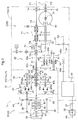
- Fig. 2 and Fig. 3 show a transmission apparatus D provided in the tractor for transmitting power outputted by the engine 3a to the front wheels 1, the rear wheels 2 and the PTO shaft 7.
- the transmission apparatus D includes a traveling transmission device D1 and an implement transmission device D2.
- the traveling transmission device D1 is configured to transmit the power outputted from the engine 3a to the traveling units such as the front wheels, the rear wheels 2, etc. via a forward/reverse switching mechanism 50 acting also as a main clutch mechanism, a hydrostatic stepless speed changer mechanism 20 as a main speed changer mechanism, a planetary gear mechanism 40 and an auxiliary speed changer mechanism 60.
- the implement transmission device D2 is configured to transmit the power outputted from the engine 3a to an implement such as the rotary cultivator implement via an implement clutch 70, an implement speed changer mechanism 71 and the PTO shaft 7.
- the power outputted by the engine 3a is inputted via the output shaft 3b to the stepless speed changer mechanism 20 and the planetary gear mechanism 40 via the forward/reverse switching mechanism 50. Then, the power is transmitted from an output shaft 48 of the planetary gear mechanism 40 to the auxiliary speed changer mechanism 60 and transmitted from an output shaft 64 of the auxiliary speed changer mechanism 60 to a rear axle 31 via a rear wheel drive shaft 32 and a rear wheel differential mechanism 33. Also, the power is transmitted from the auxiliary speed changer mechanism 60 via a gear coupling mechanism 34, a front wheel drive shaft 35, a front wheel speed changer mechanism 36 and a front wheel speed changer drive shaft 37 to a front wheel differential mechanism 38.
- the output shaft 3b constitutes what is referred to herein as an "engine output section”.
- the rear axle 31, the rear wheel drive shaft 32, the rear wheel differential mechanism 33, etc. together constitute a “rear wheel drive section” for driving the rear wheels 2.
- the rear wheel drive shaft 32 constitutes a "rear wheel drive section input section”.
- the output shaft 48 constitutes a "planetary gear mechanism output section”.
- the power outputted by the engine 3a via the output shaft 3b is inputted via the implement clutch 70 to the implement speed changer mechanism 71 to be speed-changed therein in multiple speed steps. Then, the speed-changed power is transmitted to the PTO shaft 7.
- the power of an input side power transmission shaft 72a can be selectively transmitted or non-transmitted to via the output side power transmission shaft 72b.
- the input side power transmission shaft 72a constitutes what is referred to herein as an "implement clutch input section” and the output side power transmission shaft 72b constitutes what is referred to herein as an "implement clutch output section”.
- the forward/reverse switching mechanism 50 is disposed in the clutch housing 10 provided at a front portion of the stepless speed changer case 21.
- the stepless speed changer mechanism 20 is disposed in the stepless speed changer case 21 connected to a front portion of a front transmission case 11a.
- the planetary gear mechanism 40 is disposed in the front transmission case 11a.
- the auxiliary speed changer mechanism 60, the rear wheel differential mechanism 33, the front wheel speed changer mechanism 36, the front wheel differential mechanism 38, the implement clutch 70 and the implement speed changer mechanism 71 are disposed in a rear transmission case 11b.
- the forward/reverse switching mechanism 50 includes an input shaft 51 connected to the output shaft 3b of the engine 3a to be rotatable therewith, a forward transmission section configured to transmit power of the input shaft 51 via a forward clutch 52 and a forward output gear 53 to an output shaft 55 rotatable with a transmission gear 54, and a reverse transmission section configured to transmit the power of the input shaft 51 via a reverse clutch 56, a transmission gear 57, a reverse gear 58 and a reverse output gear 59 to the output shaft 55 rotatable with the transmission gear 54.
- the input shaft 51 constitutes what is referred to herein as a "forward/reverse switching mechanism input section”.
- the output shaft 55 constitutes what is referred to herein as a "forward/reverse switching mechanism output section”.
- the forward/reverse switching mechanism 50 is rendered into a forward traveling state when the forward clutch 52 is operated into an engaged state and the reverse clutch 56 is operated into a non-engaged state, whereby the power transmitted from the output shaft 3b of the engine 3a to the input shaft 51 is converted into a forward traveling power by the forward transmission section and this power is outputted from the output shaft 55 to the stepless speed changer mechanism 20.
- the forward/reverse switching mechanism 50 is rendered into a reverse traveling state when the forward clutch 52 is operated into a disengaged state and the reverse clutch 56 is operated into an engaged state, whereby the power transmitted from the output shaft 3b of the engine 3a to the input shaft 51 is converted into a reverse traveling power by the reverse transmission section and this power is outputted from the output shaft 55 to the stepless speed changer mechanism 20.
- the forward/reverse switching mechanism 50 is rendered into a non-power-transmitting state when both the forward clutch 52 and the reverse clutch 56 are operated into the respective disengaged states, whereby the power transmitted from the output shaft 3b of the engine 3a to the input shaft 51 is not transmitted to the stepless speed changer mechanism 20.
- the forward clutch 52 and the reverse clutch 56 are constituted respectively of a wet type clutch.
- the forward/reverse switching mechanism 50 can realize a state wherein the power of the engine 3a is not transmitted to any respective mechanisms downstream of this forward/reverse switching mechanism 50. With this arrangement, it is possible to avoid increase of load torque which would occur in the case of e.g. arranging the forward/reverse switching mechanism 50 downstream of the planetary gear mechanism 40. Thus, size-up of the starter can be avoided. And, with this avoidance of size-up of the starter, increase of the space occupied by such components as the starter, a battery, a harness etc. and increase of costs thereof can be avoided advantageously.
- the stepless speed changer mechanism 20 includes a hydraulic pump 20P and a hydraulic motor 20M which are disposed inside the stepless speed changer case 21.
- the hydraulic pump 20P and the hydraulic motor 20M are disposed side by side inside the stepless speed changer case 21 in a transverse direction of the vehicle body in a plane view of the vehicle body.
- the hydraulic pump 20P is constituted of a hydraulic pump which is of variable displacement type and has an axial plunger configuration.
- the hydraulic motor 20M is constituted of a hydraulic motor of an axial plunger configuration.
- the stepless speed changer case 21 has an unillustrated port plate.
- the power outputted from the output shaft 55 of the forward/reverse switching mechanism 50 is inputted to a pump shaft 22 of the hydraulic pump 20P, whereby a cylinder block of this hydraulic pump 20P is rotatably driven by the pump shaft 22, so that the hydraulic pump 20P supplies pressure oil to the hydraulic motor 20M.
- a cylinder block of the hydraulic motor 20M is rotatably driven by the pressure oil from the hydraulic pump 20P, thereby to rotatably drive a motor shaft 25, and the power is outputted from this motor shaft 25 to the planetary gear mechanism 40.
- the pump shaft 22 constitutes what is referred to herein as a "stepless speed changer mechanism input section”
- the motor shaft 25 constitutes what is referred to herein as a "stepless speed changer mechanism output section”.
- this hydraulic cylinder effects change of an angle of the swash plate 27, whereby a speed change to a forward rotation state, a reverse rotation state or a neutral state between the forward rotation state and the reverse rotation state is effected. Further, in the event of speed change to the forward rotation state or to the reverse rotation state, the rotational speed of the hydraulic pump 20P is changed steplessly, thus steplessly changing the rotational speed of the hydraulic motor 20M, so that the rotational speed of the power to be outputted from the motor shaft 25 to the planetary gear mechanism 40 is varied steplessly.
- the stepless speed changer mechanism 20 when speed-changed to the neutral state, stops driving of the hydraulic motor 20M by the hydraulic pump 20P and stops the output from the motor shaft 25 to the planetary gear mechanism 40.
- the planetary gear mechanism 40 includes a sun gear 43 which receives power outputted from the stepless speed changer mechanism 20 and which rotatably supports a boss portion 43a via a bearing to a planetary gear case 41 provided inside the front transmission case 11a, three planet gears 44 disposed in distribution and equidistantly spaced apart from each other in the circumference of the sun gear 43, a carrier 46 which rotatably supports the respective planet gears 44 via support shafts 45 and which is configured to input the power outputted from the forward/reverse switching mechanism 50 without being steplessly speed-changed by the stepless speed changer mechanism 20, a ring gear 47 meshing with the three planet gears 44, and an output shaft 48 rotatably supported to the planetary gear case 41 via a bearing.
- the sun gear 43 constitutes what is referred to herein as a "planetary gear mechanism first input section”
- the carrier 46 constitutes what is referred to herein as a "planetary gear mechanism second input section”.
- the carrier 46 is supported to the boss portion 43a of the sun gear 43 via a bearing to be rotatable relative thereto.
- a boss portion 47a of the ring gear 47 is rotatably supported to the planetary gear case 41 via a baring and is also rotatably supported to the boss portion 43a of the sun gear 43 via a bearing.
- each planet gear 44 is supported to the carrier 46 in a cantilever-manner, with being connected to the carrier 46 at one end side only.
- the three support shafts 45 are connected via a single annular support plate so that meshed states of the planet gears 44 relative to the sun gear 43 and the ring gear 47 are maintained thereby.
- the planetary gear case 41 rotatably supports an input rotary body 42 in the form of a tubular shaft.
- This input rotary body 42 is operably coupled with the motor shaft 25 to be rotatable therewith via a spline engagement arrangement.
- the input rotary body 42 and the sun gear 43 are operably coupled with each other via meshing between a transmission gear 42a provided on the outer circumference side of the input rotary body 42 to be rotatable therewith and a driven gear 43b provided on the outer circumference portion of the boss portion 43a of the sun gear 43 to be rotatable therewith.
- the ring gear 47 is operably coupled with the output shaft 48 via a spline arrangement provided between the boss portion 47a and the output shaft 48.
- An input rotary body 49 in the form of a tubular shaft is rotatably supported to the planetary gear case 41.
- This input rotary body 49 is operably coupled with the pump shaft 22 to be rotatable therewith, through a spline engagement arrangement.
- the input rotary body 49 and the carrier 46 are operably coupled with each other via meshing between a transmission gear 49a provided on the outer circumference side of the input rotary body 49 to be rotatable therewith and a driven gear 46a provided on the outer circumference portin of the carrier 46 to be rotatable therewith.
- the power outputted from the output shaft 55 by the forward/reverse switching mechanism 50 is inputted to the input rotary body 49 via the pump shaft 22, whereby the power from the forward/reverse switching mechanism 50 is inputted to the carrier 46 without being subjected to the speed changing effect of the stepless speed changer mechanism 20 and the power outputted from the motor shaft 25 by the stepless speed changer mechanism 50 is inputted to the sun gear 43, so that the power from the stepless speed changer mechanism 20 and the power from the forward/reverse switching mechanism 50 not subjected to the speed changing effect of the stepless speed changer mechanism 20 are synthetized and the resultant synthesized power is outputted from the output shaft 48 to the auxiliary speed changer mechanism 60.
- the auxiliary speed changer mechanism 60 includes an input shaft 61 formed integral with the output shaft 48 of the planetary gear mechanism 40, a first gear 62a and a second gear 63a which are mounted on this input shaft 61 to be rotatable therewith, a third gear 62b meshed with the first gear 62a and mounted on the output shaft 64 to be rotatable relative thereto, a fourth gear 63b meshed with the second gear 63a and mounted on the output shaft 64 to be rotatable relative thereto, a first transmission clutch 65 mounted on the output shaft 64 to be rotatable therewith and connectable to either the third gear 62b or the fourth gear 63b, a fifth gear 66b rotatable with the fourth gear 63b, a sixth gear 66a meshed with the fifth gear 66b and mounted on a transmission shaft 67 to be rotatable therewith, a seventh gear 69a connectable with the transmission shaft 67 via a second transmission clutch 68, and an eighth gear 69b meshed with the
- the rear wheel drive shaft 32 is operably coupled via a spline engagement arrangement with the output shaft 64 of the auxiliary speed changer mechanism 60 to be rotatable therewith.
- the power outputted from the output shaft 64 is transmitted from the rear wheel drive shaft 32 via the rear wheel differential mechanism 33 to the rear wheels 2.
- the power outputted from the output shaft 64 is transmitted via the gear coupling mechanism 34 to the front wheel drive shaft 35 operably coupled with the rear wheel drive shaft 32 and transmitted via the front wheel speed changer mechanism 36 to the front wheel speed changer drive shaft 37 and then transmitted from this front wheel speed changer drive shaft 37 via the front wheel differential mechanism 38 to the front wheels 1.
- the output of the engine 3a is switched over between a forward drive and a reverse drive by the forward/reverse switching mechanism 50.
- the forward drive and the reverse drive outputted from the forward/reverse switching mechanism 50 is steplessly speed-changed by the planetary gear mechanism 40 and the output of its output shaft 48 is speed changed in a plurality of steps of a low speed, an intermediate speed and a high speed by the auxiliary speed changer mechanism 60 and the forward drive and the reverse drive speed-changed by the auxiliary speed changer mechanism 60 is transmitted from the output shaft 64 of the auxiliary speed changer mechanism 60 via the rear wheel differential mechanism 33 to drive the rear wheels 2 and also from the output shaft 64 of the auxiliary speed changer mechanism 60 via the gear coupling mechanism 34, the front wheel speed speed changer mechanism 36 and the front wheel differential mechanism 38 to drive the front wheels 1.
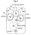
- the output shaft 3b of the engine 3a, the input shaft 51 of the forward/reverse switching mechanism 50, the sun gear 43, the carrier 46 and the output shaft 48 of the planetary gear mechanism 40 , the input shaft 61 of the auxiliary speed changer mechanism 60, the input side power transmission shaft 72a and the output side power transmission shaft 72b of the implement clutch 70, and a power speed changer transmission shaft 73 of the implement speed changer mechanism 71 all have their respective rotational axes disposed on a common first axis P1.
- the input shaft 51 of the forward/reverse switching mechanism 50, the sun gear 43, the carrier 46 and the output shaft 48 of the planetary gear mechanism 40 , the input shaft 61 of the auxiliary speed changer mechanism 60, the input side power transmission shaft 72a and the output side power transmission shaft 72b of the implement clutch 70, and a power speed changer transmission shaft 73 of the implement speed changer mechanism 71 all have their respective rotational axes disposed on a common first axis P1 coaxial with the rotational axis of the output shaft 3b of the engine 3a.
- This arrangement serves to avoid increase of space and deterioration in transmission efficiency.
- the output shaft 64 of the auxiliary speed changer mechanism 60, the rear wheel differential mechanism 33, the brake shaft or the rear axle 31 of the rear wheels 2, and the PTO shaft 7 which receives transmission of power via a gear 74 and a gear 75 from the power speed changer transmission mechanism 73 have their respective rotational axes disposed on a common second axis P2.
- the height of this second axis P2 is set lower than the first axis P1.
- the pump shaft 22 and the motor shaft 25 are disposed in distribution on the left and right sides of the first axis P1 in the front view of the vehicle body such that the heights of a third axis P3 in agreement with the rotational axis of the pump shaft 22 and a fourth axis P4 in agreement with the rotational axis of the motor shaft 25 are set at positions lower than the first axis P1 and higher than the second axis P2.
- the third axis P3 is disposed on the left side of the first axis P1 and the fourth axis P4 is disposed on the right side of the first axis P1, and the third axis P3 is set at a position slightly higher than the fourth axis P4.
- the stepless speed changer mechanism 20 includes at least a hydraulic circuit disposed between the hydraulic pump 20P and the hydraulic motor 20M and mechanisms such as the hydraulic cylinder for driving the swash plate 27 of the hydraulic pump 20P, thus requiring certain amount of space for disposing these components.
- the stepless speed changer mechanism 20 were disposed only on either left or right side of the first axis P1 in the front view of the tractor, this would cause need for reinforcement of the vehicle body frame 5 on which the stepless speed changer mechanism is mounted or increase of the vehicle width.
- the output shaft 55 of the forward/reverse switching mechanism 50 is provided continuously with the pump shaft 22 to be rotatable therewith via the spline engagement arrangement, to this output shaft 55 is coaxial with the third axis P3. Further, the transmission shaft 67 of the auxiliary speed changer mechanism 60 is not directly coupled with the pump shaft 22, but is disposed substantially on the roughly same axis as the third axis P3, rearwardly of the pump shaft 22.
- the fifth axis P5 in agreement with the respective rotational axes of the front wheel drive shaft 35 and the clutch of the front wheel speed changer mechanism 36 is disposed at a position lower than the second axis P2 and slightly on the left side of the second axis P2 and on the right side of the third axis P3, in the vehicle body front view.
- the sixth axis P6 in agreement with the respective rotational axes of the front wheel speed changer shaft 37 and the front wheel differential mechanism 38 is disposed at a position lower than the fifth axis P5 and slightly on the left side of the second axis P2 and on the right side of the fifth axis P5 in the vehicle body front view.
- the lubricant oil level is set at substantially same level as the second axis P2, and the output shaft 3b of the engine 3a, the forward/reverse switching mechanism 50, the planetary gear mechanism 40, a portion of the auxiliary speed changer mechanism 60, the implement clutch 70, the implement speed changer mechanism 71 and the hydraulic pump 20P are disposed upwardly of the oil level.
- a portion of the auxiliary speed changer mechanism 60, the brake shaft or the rear axle 31 of the rear wheels 2 and the PTO shaft 7 are disposed at the oil level.
- the front wheel drive shaft 35, the clutch of the front wheel speed changer mechanism 36, the front wheel speed changer drive shaft 37, the front wheel differential mechanism 38 and the brake shaft or the front axle 39 of the front wheels 1 are disposed downwardly of the oil level.
- the brake shaft or the front axles 39 of the front wheels 1 and the brake shaft or the rear axle 31 of the rear wheels 2 are placed in constant contact with the lubricant oil, so frictional heat generated by braking can be cooled speedily.
- the engine 3a of the tractor will be started up with the forward clutch 52 and the reverse clutch 56 of the forward/reverse switching mechanism 50 and the implement clutch 70 being disengaged. Namely, this startup of the engine 3a of the tractor can be effected with being disconnected from the traveling transmission device D1 and the implement transmission device D2. Therefore, through reduction of the load torque at the time of startup of the engine 3a, size-up of the starter can be avoided.
- the transmission apparatus D of the present invention can be readily incorporated in the existing tractor also.
Applications Claiming Priority (1)
| Application Number | Priority Date | Filing Date | Title |
|---|---|---|---|
| JP2015086750A JP6396841B2 (ja) | 2015-04-21 | 2015-04-21 | トラクタに備えられる伝動装置 |
Publications (2)
| Publication Number | Publication Date |
|---|---|
| EP3085992A1 true EP3085992A1 (de) | 2016-10-26 |
| EP3085992B1 EP3085992B1 (de) | 2018-01-17 |
Family
ID=55802301
Family Applications (1)
| Application Number | Title | Priority Date | Filing Date |
|---|---|---|---|
| EP16166406.5A Active EP3085992B1 (de) | 2015-04-21 | 2016-04-21 | Getriebevorrichtung |
Country Status (5)
| Country | Link |
|---|---|
| US (1) | US9945464B2 (de) |
| EP (1) | EP3085992B1 (de) |
| JP (1) | JP6396841B2 (de) |
| KR (1) | KR101811522B1 (de) |
| CN (1) | CN106064562B (de) |
Families Citing this family (13)
| Publication number | Priority date | Publication date | Assignee | Title |
|---|---|---|---|---|
| CN106740080B (zh) * | 2017-03-23 | 2023-08-18 | 长沙桑铼特农业机械设备有限公司 | 一种变速箱及农业机械 |
| US10935109B2 (en) * | 2017-06-22 | 2021-03-02 | Kubota Corporation | Work vehicle transmission and work vehicle having the same |
| BR102018071693A2 (pt) * | 2017-12-07 | 2019-06-25 | Deere & Company | Dispositivo combinado arrancador de propulsor e gerador de potência, e, conjunto de trem de acionamento |
| US11204097B2 (en) * | 2018-10-19 | 2021-12-21 | Kanzaki Kokyukoki Mfg. Co., Ltd. | Transmission structure and working vehicle |
| EP3904728A4 (de) * | 2018-12-27 | 2023-02-22 | Kubota Corporation | Nutzfahrzeug |
| CN109723789B (zh) * | 2019-01-16 | 2021-07-20 | 江苏大学 | 一种混合动力多模式切换的无级变速传动系统 |
| WO2020190042A1 (ko) * | 2019-03-20 | 2020-09-24 | 엘에스엠트론 주식회사 | 농업용 작업차량의 변속장치 |
| DE102019206979A1 (de) * | 2019-05-14 | 2020-11-19 | Deere & Company | Lastschaltgetriebe für Landmaschinen |
| WO2020244091A1 (zh) * | 2019-06-06 | 2020-12-10 | 丰疆智能科技研究院(常州)有限公司 | 插秧机、变速箱、变速箱壳体以及插秧机动力传输方法 |
| JP7390987B2 (ja) | 2019-09-26 | 2023-12-04 | 株式会社クボタ | トラクターの走行伝動装置 |
| EP3798468A3 (de) | 2019-09-26 | 2021-10-06 | Kubota Corporation | Fahrgetriebe eines traktors |
| CN112455221A (zh) * | 2019-11-12 | 2021-03-09 | 丰疆智能科技股份有限公司 | 拖拉机、后桥动力输出装置以及拖拉机的工作方法 |
| CN114885620B (zh) * | 2022-03-01 | 2023-05-09 | 江苏金云农业装备有限公司 | 一种农用耕地整理的无级变速旋耕机 |
Citations (6)
| Publication number | Priority date | Publication date | Assignee | Title |
|---|---|---|---|---|
| US3969958A (en) * | 1973-03-28 | 1976-07-20 | Aisin Seiki Kabushiki Kaisha | Output split type hydrostatic transmission |
| DE3726081A1 (de) * | 1987-08-06 | 1989-02-16 | Man Nutzfahrzeuge Gmbh | Antriebseinrichtung eines fahrzeuges, insbesondere nutzfahrzeuges |
| DE4125988A1 (de) * | 1990-07-06 | 1993-01-07 | Claas Ohg | Hydrostisch-leistungsverzweigtes mehrganggetriebe |
| US20100184551A1 (en) * | 2007-09-20 | 2010-07-22 | Kubota Corporation | Speed Change Transmission System |
| JP2012040944A (ja) | 2010-08-19 | 2012-03-01 | Kubota Corp | トラクタの伝動装置 |
| US20140357447A1 (en) * | 2011-06-14 | 2014-12-04 | Valtra Oy Ab | Continuously variable power-split vehicle transmission |
Family Cites Families (16)
| Publication number | Priority date | Publication date | Assignee | Title |
|---|---|---|---|---|
| DE4021643A1 (de) | 1990-07-06 | 1992-01-16 | Claas Ohg | Hydrostatisch-leistungsverzweigtes mehrgang-lastschaltgetriebe |
| DE59105674D1 (de) * | 1991-07-04 | 1995-07-13 | Claas Ohg | Hydrostatisch-leistungsverzweigtes Lastschaltgetriebe. |
| US5931758A (en) * | 1998-04-08 | 1999-08-03 | General Dynamics Land Systems, Inc. | Simplified multi-range hydromechanical transmission for vehicles |
| DE60226760D1 (de) * | 2001-10-22 | 2008-07-03 | Yanmar Co Ltd | Fahrzeug mit hydraulikgetriebe |
| JP2007062645A (ja) * | 2005-09-01 | 2007-03-15 | Kubota Corp | 作業機のpto伝動構造 |
| JP4467501B2 (ja) * | 2005-09-30 | 2010-05-26 | 株式会社クボタ | トラクタの変速伝動装置 |
| US8047942B2 (en) * | 2006-07-06 | 2011-11-01 | Kubota Corporation | Speed change transmission apparatus |
| KR101143062B1 (ko) * | 2007-02-05 | 2012-05-11 | 가부시끼 가이샤 구보다 | 변속 전동 장치 |
| ATE524341T1 (de) * | 2007-03-05 | 2011-09-15 | Kubota Kk | Übertragungseinrichtung |
| GB0709636D0 (en) * | 2007-05-19 | 2007-06-27 | Valtra Inc | Rotation sensing |
| JP2009074616A (ja) * | 2007-09-20 | 2009-04-09 | Kubota Corp | 変速伝動装置 |
| JP5492037B2 (ja) | 2010-09-14 | 2014-05-14 | 株式会社クボタ | トラクタの伝動装置 |
| GB201109963D0 (en) * | 2011-06-14 | 2011-07-27 | Valtra Oy Ab | Power shuttle transmission module |
| GB201109967D0 (en) * | 2011-06-14 | 2011-07-27 | Valtra Oy Ab | Continuously variable power-split vehicle transmission |
| GB201109970D0 (en) * | 2011-06-14 | 2011-07-27 | Valtra Oy Ab | Continuously variable power-split vehicle transmission |
| JP5763435B2 (ja) * | 2011-06-17 | 2015-08-12 | 株式会社クボタ | 作業車の伝動切り換え構造 |
-
2015
- 2015-04-21 JP JP2015086750A patent/JP6396841B2/ja active Active
-
2016
- 2016-04-18 KR KR1020160046881A patent/KR101811522B1/ko active IP Right Grant
- 2016-04-18 US US15/131,240 patent/US9945464B2/en active Active
- 2016-04-18 CN CN201610243097.8A patent/CN106064562B/zh active Active
- 2016-04-21 EP EP16166406.5A patent/EP3085992B1/de active Active
Patent Citations (6)
| Publication number | Priority date | Publication date | Assignee | Title |
|---|---|---|---|---|
| US3969958A (en) * | 1973-03-28 | 1976-07-20 | Aisin Seiki Kabushiki Kaisha | Output split type hydrostatic transmission |
| DE3726081A1 (de) * | 1987-08-06 | 1989-02-16 | Man Nutzfahrzeuge Gmbh | Antriebseinrichtung eines fahrzeuges, insbesondere nutzfahrzeuges |
| DE4125988A1 (de) * | 1990-07-06 | 1993-01-07 | Claas Ohg | Hydrostisch-leistungsverzweigtes mehrganggetriebe |
| US20100184551A1 (en) * | 2007-09-20 | 2010-07-22 | Kubota Corporation | Speed Change Transmission System |
| JP2012040944A (ja) | 2010-08-19 | 2012-03-01 | Kubota Corp | トラクタの伝動装置 |
| US20140357447A1 (en) * | 2011-06-14 | 2014-12-04 | Valtra Oy Ab | Continuously variable power-split vehicle transmission |
Also Published As
| Publication number | Publication date |
|---|---|
| KR20160125296A (ko) | 2016-10-31 |
| KR101811522B1 (ko) | 2017-12-21 |
| CN106064562A (zh) | 2016-11-02 |
| US9945464B2 (en) | 2018-04-17 |
| JP2016203767A (ja) | 2016-12-08 |
| CN106064562B (zh) | 2018-10-30 |
| US20160312872A1 (en) | 2016-10-27 |
| EP3085992B1 (de) | 2018-01-17 |
| JP6396841B2 (ja) | 2018-09-26 |
Similar Documents
| Publication | Publication Date | Title |
|---|---|---|
| EP3085992B1 (de) | Getriebevorrichtung | |
| US8657713B2 (en) | Power train for work vehicle | |
| US7887449B2 (en) | Speed-change transmission apparatus | |
| US7559865B2 (en) | Transmission apparatus for a working vehicle | |
| KR101383135B1 (ko) | 트랜스미션 | |
| US10086696B2 (en) | Agricultural working vehicle transmission combination | |
| US4373597A (en) | Tractor for agriculture | |
| EP2934936B1 (de) | Getriebe für landwirtschaftliches fahrzeug | |
| EP1378686B1 (de) | Stufenloses Getriebe für Kraftfahrzeuge, insbesondere für landwirtschaftliche Traktoren | |
| US6821225B2 (en) | Transmission apparatus for a working vehicle | |
| US7179188B2 (en) | Transmission apparatus for a working vehicle | |
| US11629781B2 (en) | Work vehicle | |
| JP6628842B2 (ja) | 伝動装置 | |
| KR100725549B1 (ko) | 트랙터의 트랜스미션 | |
| CN210344179U (zh) | 一种拖拉机及动力传递装置 | |
| US20220397189A1 (en) | Power transmission device for work vehicle | |
| JP2023005474A (ja) | 作業車両の動力伝達装置 | |
| US20230417313A1 (en) | Work vehicle | |
| JP6904323B2 (ja) | 作業車両 | |
| JP2006029418A (ja) | 走行作業機における動力伝達装置 | |
| WO2014096451A1 (en) | Vehicle transmission | |
| JPH09112637A (ja) | 変速装置 | |
| CN117429242A (zh) | 驱动桥总成及具有其的电动拖拉机 | |
| WO2014096447A1 (en) | Agricultural vehicle transmission | |
| WO2014096450A1 (en) | Agricultural vehicle transmission |
Legal Events
| Date | Code | Title | Description |
|---|---|---|---|
| PUAI | Public reference made under article 153(3) epc to a published international application that has entered the european phase |
Free format text: ORIGINAL CODE: 0009012 |
|
| AK | Designated contracting states |
Kind code of ref document: A1 Designated state(s): AL AT BE BG CH CY CZ DE DK EE ES FI FR GB GR HR HU IE IS IT LI LT LU LV MC MK MT NL NO PL PT RO RS SE SI SK SM TR |
|
| AX | Request for extension of the european patent |
Extension state: BA ME |
|
| 17P | Request for examination filed |
Effective date: 20170426 |
|
| RBV | Designated contracting states (corrected) |
Designated state(s): AL AT BE BG CH CY CZ DE DK EE ES FI FR GB GR HR HU IE IS IT LI LT LU LV MC MK MT NL NO PL PT RO RS SE SI SK SM TR |
|
| GRAP | Despatch of communication of intention to grant a patent |
Free format text: ORIGINAL CODE: EPIDOSNIGR1 |
|
| RIC1 | Information provided on ipc code assigned before grant |
Ipc: F16H 47/04 20060101AFI20170629BHEP |
|
| INTG | Intention to grant announced |
Effective date: 20170725 |
|
| GRAS | Grant fee paid |
Free format text: ORIGINAL CODE: EPIDOSNIGR3 |
|
| GRAA | (expected) grant |
Free format text: ORIGINAL CODE: 0009210 |
|
| AK | Designated contracting states |
Kind code of ref document: B1 Designated state(s): AL AT BE BG CH CY CZ DE DK EE ES FI FR GB GR HR HU IE IS IT LI LT LU LV MC MK MT NL NO PL PT RO RS SE SI SK SM TR |
|
| REG | Reference to a national code |
Ref country code: GB Ref legal event code: FG4D |
|
| REG | Reference to a national code |
Ref country code: CH Ref legal event code: EP |
|
| REG | Reference to a national code |
Ref country code: IE Ref legal event code: FG4D |
|
| REG | Reference to a national code |
Ref country code: AT Ref legal event code: REF Ref document number: 964653 Country of ref document: AT Kind code of ref document: T Effective date: 20180215 |
|
| REG | Reference to a national code |
Ref country code: DE Ref legal event code: R096 Ref document number: 602016001345 Country of ref document: DE |
|
| REG | Reference to a national code |
Ref country code: FR Ref legal event code: PLFP Year of fee payment: 3 |
|
| REG | Reference to a national code |
Ref country code: NL Ref legal event code: MP Effective date: 20180117 |
|
| REG | Reference to a national code |
Ref country code: LT Ref legal event code: MG4D |
|
| REG | Reference to a national code |
Ref country code: AT Ref legal event code: MK05 Ref document number: 964653 Country of ref document: AT Kind code of ref document: T Effective date: 20180117 |
|
| PG25 | Lapsed in a contracting state [announced via postgrant information from national office to epo] |
Ref country code: NL Free format text: LAPSE BECAUSE OF FAILURE TO SUBMIT A TRANSLATION OF THE DESCRIPTION OR TO PAY THE FEE WITHIN THE PRESCRIBED TIME-LIMIT Effective date: 20180117 |
|
| PG25 | Lapsed in a contracting state [announced via postgrant information from national office to epo] |
Ref country code: ES Free format text: LAPSE BECAUSE OF FAILURE TO SUBMIT A TRANSLATION OF THE DESCRIPTION OR TO PAY THE FEE WITHIN THE PRESCRIBED TIME-LIMIT Effective date: 20180117 Ref country code: CY Free format text: LAPSE BECAUSE OF FAILURE TO SUBMIT A TRANSLATION OF THE DESCRIPTION OR TO PAY THE FEE WITHIN THE PRESCRIBED TIME-LIMIT Effective date: 20180117 Ref country code: FI Free format text: LAPSE BECAUSE OF FAILURE TO SUBMIT A TRANSLATION OF THE DESCRIPTION OR TO PAY THE FEE WITHIN THE PRESCRIBED TIME-LIMIT Effective date: 20180117 Ref country code: NO Free format text: LAPSE BECAUSE OF FAILURE TO SUBMIT A TRANSLATION OF THE DESCRIPTION OR TO PAY THE FEE WITHIN THE PRESCRIBED TIME-LIMIT Effective date: 20180417 Ref country code: LT Free format text: LAPSE BECAUSE OF FAILURE TO SUBMIT A TRANSLATION OF THE DESCRIPTION OR TO PAY THE FEE WITHIN THE PRESCRIBED TIME-LIMIT Effective date: 20180117 Ref country code: HR Free format text: LAPSE BECAUSE OF FAILURE TO SUBMIT A TRANSLATION OF THE DESCRIPTION OR TO PAY THE FEE WITHIN THE PRESCRIBED TIME-LIMIT Effective date: 20180117 |
|
| PG25 | Lapsed in a contracting state [announced via postgrant information from national office to epo] |
Ref country code: AT Free format text: LAPSE BECAUSE OF FAILURE TO SUBMIT A TRANSLATION OF THE DESCRIPTION OR TO PAY THE FEE WITHIN THE PRESCRIBED TIME-LIMIT Effective date: 20180117 Ref country code: BG Free format text: LAPSE BECAUSE OF FAILURE TO SUBMIT A TRANSLATION OF THE DESCRIPTION OR TO PAY THE FEE WITHIN THE PRESCRIBED TIME-LIMIT Effective date: 20180417 Ref country code: RS Free format text: LAPSE BECAUSE OF FAILURE TO SUBMIT A TRANSLATION OF THE DESCRIPTION OR TO PAY THE FEE WITHIN THE PRESCRIBED TIME-LIMIT Effective date: 20180117 Ref country code: IS Free format text: LAPSE BECAUSE OF FAILURE TO SUBMIT A TRANSLATION OF THE DESCRIPTION OR TO PAY THE FEE WITHIN THE PRESCRIBED TIME-LIMIT Effective date: 20180517 Ref country code: LV Free format text: LAPSE BECAUSE OF FAILURE TO SUBMIT A TRANSLATION OF THE DESCRIPTION OR TO PAY THE FEE WITHIN THE PRESCRIBED TIME-LIMIT Effective date: 20180117 Ref country code: SE Free format text: LAPSE BECAUSE OF FAILURE TO SUBMIT A TRANSLATION OF THE DESCRIPTION OR TO PAY THE FEE WITHIN THE PRESCRIBED TIME-LIMIT Effective date: 20180117 Ref country code: PL Free format text: LAPSE BECAUSE OF FAILURE TO SUBMIT A TRANSLATION OF THE DESCRIPTION OR TO PAY THE FEE WITHIN THE PRESCRIBED TIME-LIMIT Effective date: 20180117 Ref country code: GR Free format text: LAPSE BECAUSE OF FAILURE TO SUBMIT A TRANSLATION OF THE DESCRIPTION OR TO PAY THE FEE WITHIN THE PRESCRIBED TIME-LIMIT Effective date: 20180418 |
|
| REG | Reference to a national code |
Ref country code: DE Ref legal event code: R097 Ref document number: 602016001345 Country of ref document: DE |
|
| PG25 | Lapsed in a contracting state [announced via postgrant information from national office to epo] |
Ref country code: RO Free format text: LAPSE BECAUSE OF FAILURE TO SUBMIT A TRANSLATION OF THE DESCRIPTION OR TO PAY THE FEE WITHIN THE PRESCRIBED TIME-LIMIT Effective date: 20180117 Ref country code: IT Free format text: LAPSE BECAUSE OF FAILURE TO SUBMIT A TRANSLATION OF THE DESCRIPTION OR TO PAY THE FEE WITHIN THE PRESCRIBED TIME-LIMIT Effective date: 20180117 Ref country code: EE Free format text: LAPSE BECAUSE OF FAILURE TO SUBMIT A TRANSLATION OF THE DESCRIPTION OR TO PAY THE FEE WITHIN THE PRESCRIBED TIME-LIMIT Effective date: 20180117 Ref country code: AL Free format text: LAPSE BECAUSE OF FAILURE TO SUBMIT A TRANSLATION OF THE DESCRIPTION OR TO PAY THE FEE WITHIN THE PRESCRIBED TIME-LIMIT Effective date: 20180117 |
|
| PLBE | No opposition filed within time limit |
Free format text: ORIGINAL CODE: 0009261 |
|
| STAA | Information on the status of an ep patent application or granted ep patent |
Free format text: STATUS: NO OPPOSITION FILED WITHIN TIME LIMIT |
|
| PG25 | Lapsed in a contracting state [announced via postgrant information from national office to epo] |
Ref country code: SM Free format text: LAPSE BECAUSE OF FAILURE TO SUBMIT A TRANSLATION OF THE DESCRIPTION OR TO PAY THE FEE WITHIN THE PRESCRIBED TIME-LIMIT Effective date: 20180117 Ref country code: DK Free format text: LAPSE BECAUSE OF FAILURE TO SUBMIT A TRANSLATION OF THE DESCRIPTION OR TO PAY THE FEE WITHIN THE PRESCRIBED TIME-LIMIT Effective date: 20180117 Ref country code: CZ Free format text: LAPSE BECAUSE OF FAILURE TO SUBMIT A TRANSLATION OF THE DESCRIPTION OR TO PAY THE FEE WITHIN THE PRESCRIBED TIME-LIMIT Effective date: 20180117 Ref country code: SK Free format text: LAPSE BECAUSE OF FAILURE TO SUBMIT A TRANSLATION OF THE DESCRIPTION OR TO PAY THE FEE WITHIN THE PRESCRIBED TIME-LIMIT Effective date: 20180117 Ref country code: MC Free format text: LAPSE BECAUSE OF FAILURE TO SUBMIT A TRANSLATION OF THE DESCRIPTION OR TO PAY THE FEE WITHIN THE PRESCRIBED TIME-LIMIT Effective date: 20180117 |
|
| REG | Reference to a national code |
Ref country code: BE Ref legal event code: MM Effective date: 20180430 |
|
| 26N | No opposition filed |
Effective date: 20181018 |
|
| REG | Reference to a national code |
Ref country code: IE Ref legal event code: MM4A |
|
| PG25 | Lapsed in a contracting state [announced via postgrant information from national office to epo] |
Ref country code: LU Free format text: LAPSE BECAUSE OF NON-PAYMENT OF DUE FEES Effective date: 20180421 |
|
| PG25 | Lapsed in a contracting state [announced via postgrant information from national office to epo] |
Ref country code: BE Free format text: LAPSE BECAUSE OF NON-PAYMENT OF DUE FEES Effective date: 20180430 Ref country code: SI Free format text: LAPSE BECAUSE OF FAILURE TO SUBMIT A TRANSLATION OF THE DESCRIPTION OR TO PAY THE FEE WITHIN THE PRESCRIBED TIME-LIMIT Effective date: 20180117 |
|
| PG25 | Lapsed in a contracting state [announced via postgrant information from national office to epo] |
Ref country code: IE Free format text: LAPSE BECAUSE OF NON-PAYMENT OF DUE FEES Effective date: 20180421 |
|
| REG | Reference to a national code |
Ref country code: CH Ref legal event code: PL |
|
| PG25 | Lapsed in a contracting state [announced via postgrant information from national office to epo] |
Ref country code: LI Free format text: LAPSE BECAUSE OF NON-PAYMENT OF DUE FEES Effective date: 20190430 Ref country code: MT Free format text: LAPSE BECAUSE OF NON-PAYMENT OF DUE FEES Effective date: 20180421 Ref country code: CH Free format text: LAPSE BECAUSE OF NON-PAYMENT OF DUE FEES Effective date: 20190430 |
|
| PG25 | Lapsed in a contracting state [announced via postgrant information from national office to epo] |
Ref country code: TR Free format text: LAPSE BECAUSE OF FAILURE TO SUBMIT A TRANSLATION OF THE DESCRIPTION OR TO PAY THE FEE WITHIN THE PRESCRIBED TIME-LIMIT Effective date: 20180117 |
|
| PG25 | Lapsed in a contracting state [announced via postgrant information from national office to epo] |
Ref country code: PT Free format text: LAPSE BECAUSE OF FAILURE TO SUBMIT A TRANSLATION OF THE DESCRIPTION OR TO PAY THE FEE WITHIN THE PRESCRIBED TIME-LIMIT Effective date: 20180117 |
|
| PG25 | Lapsed in a contracting state [announced via postgrant information from national office to epo] |
Ref country code: HU Free format text: LAPSE BECAUSE OF FAILURE TO SUBMIT A TRANSLATION OF THE DESCRIPTION OR TO PAY THE FEE WITHIN THE PRESCRIBED TIME-LIMIT; INVALID AB INITIO Effective date: 20160421 Ref country code: MK Free format text: LAPSE BECAUSE OF NON-PAYMENT OF DUE FEES Effective date: 20180117 |
|
| GBPC | Gb: european patent ceased through non-payment of renewal fee |
Effective date: 20200421 |
|
| PG25 | Lapsed in a contracting state [announced via postgrant information from national office to epo] |
Ref country code: GB Free format text: LAPSE BECAUSE OF NON-PAYMENT OF DUE FEES Effective date: 20200421 |
|
| REG | Reference to a national code |
Ref country code: DE Ref legal event code: R082 Ref document number: 602016001345 Country of ref document: DE Representative=s name: CBDL PATENTANWAELTE GBR, DE |
|
| PGFP | Annual fee paid to national office [announced via postgrant information from national office to epo] |
Ref country code: FR Payment date: 20230309 Year of fee payment: 8 |
|
| PGFP | Annual fee paid to national office [announced via postgrant information from national office to epo] |
Ref country code: DE Payment date: 20230228 Year of fee payment: 8 |