EP3083408B1 - Abfüllvorrichtung und deren verwendung zur abfüllung eines fluids - Google Patents
Abfüllvorrichtung und deren verwendung zur abfüllung eines fluids Download PDFInfo
- Publication number
- EP3083408B1 EP3083408B1 EP14812712.9A EP14812712A EP3083408B1 EP 3083408 B1 EP3083408 B1 EP 3083408B1 EP 14812712 A EP14812712 A EP 14812712A EP 3083408 B1 EP3083408 B1 EP 3083408B1
- Authority
- EP
- European Patent Office
- Prior art keywords
- filling
- khz
- ccy
- container
- cpy
- Prior art date
- Legal status (The legal status is an assumption and is not a legal conclusion. Google has not performed a legal analysis and makes no representation as to the accuracy of the status listed.)
- Active
Links
Images

Classifications
-
- B—PERFORMING OPERATIONS; TRANSPORTING
- B65—CONVEYING; PACKING; STORING; HANDLING THIN OR FILAMENTARY MATERIAL
- B65B—MACHINES, APPARATUS OR DEVICES FOR, OR METHODS OF, PACKAGING ARTICLES OR MATERIALS; UNPACKING
- B65B3/00—Packaging plastic material, semiliquids, liquids or mixed solids and liquids, in individual containers or receptacles, e.g. bags, sacks, boxes, cartons, cans, or jars
- B65B3/26—Methods or devices for controlling the quantity of the material fed or filled
- B65B3/28—Methods or devices for controlling the quantity of the material fed or filled by weighing
-
- B—PERFORMING OPERATIONS; TRANSPORTING
- B65—CONVEYING; PACKING; STORING; HANDLING THIN OR FILAMENTARY MATERIAL
- B65B—MACHINES, APPARATUS OR DEVICES FOR, OR METHODS OF, PACKAGING ARTICLES OR MATERIALS; UNPACKING
- B65B31/00—Packaging articles or materials under special atmospheric or gaseous conditions; Adding propellants to aerosol containers
-
- B—PERFORMING OPERATIONS; TRANSPORTING
- B65—CONVEYING; PACKING; STORING; HANDLING THIN OR FILAMENTARY MATERIAL
- B65B—MACHINES, APPARATUS OR DEVICES FOR, OR METHODS OF, PACKAGING ARTICLES OR MATERIALS; UNPACKING
- B65B39/00—Nozzles, funnels or guides for introducing articles or materials into containers or wrappers
- B65B39/12—Nozzles, funnels or guides for introducing articles or materials into containers or wrappers movable towards or away from container or wrapper during filling or depositing
-
- B—PERFORMING OPERATIONS; TRANSPORTING
- B65—CONVEYING; PACKING; STORING; HANDLING THIN OR FILAMENTARY MATERIAL
- B65B—MACHINES, APPARATUS OR DEVICES FOR, OR METHODS OF, PACKAGING ARTICLES OR MATERIALS; UNPACKING
- B65B43/00—Forming, feeding, opening or setting-up containers or receptacles in association with packaging
- B65B43/42—Feeding or positioning bags, boxes, or cartons in the distended, opened, or set-up state; Feeding preformed rigid containers, e.g. tins, capsules, glass tubes, glasses, to the packaging position; Locating containers or receptacles at the filling position; Supporting containers or receptacles during the filling operation
- B65B43/54—Means for supporting containers or receptacles during the filling operation
- B65B43/59—Means for supporting containers or receptacles during the filling operation vertically movable
-
- B—PERFORMING OPERATIONS; TRANSPORTING
- B65—CONVEYING; PACKING; STORING; HANDLING THIN OR FILAMENTARY MATERIAL
- B65B—MACHINES, APPARATUS OR DEVICES FOR, OR METHODS OF, PACKAGING ARTICLES OR MATERIALS; UNPACKING
- B65B57/00—Automatic control, checking, warning, or safety devices
- B65B57/02—Automatic control, checking, warning, or safety devices responsive to absence, presence, abnormal feed, or misplacement of binding or wrapping material, containers, or packages
- B65B57/04—Automatic control, checking, warning, or safety devices responsive to absence, presence, abnormal feed, or misplacement of binding or wrapping material, containers, or packages and operating to control, or to stop, the feed of such material, containers, or packages
-
- B—PERFORMING OPERATIONS; TRANSPORTING
- B65—CONVEYING; PACKING; STORING; HANDLING THIN OR FILAMENTARY MATERIAL
- B65B—MACHINES, APPARATUS OR DEVICES FOR, OR METHODS OF, PACKAGING ARTICLES OR MATERIALS; UNPACKING
- B65B57/00—Automatic control, checking, warning, or safety devices
- B65B57/10—Automatic control, checking, warning, or safety devices responsive to absence, presence, abnormal feed, or misplacement of articles or materials to be packaged
- B65B57/14—Automatic control, checking, warning, or safety devices responsive to absence, presence, abnormal feed, or misplacement of articles or materials to be packaged and operating to control, or stop, the feed of articles or material to be packaged
- B65B57/145—Automatic control, checking, warning, or safety devices responsive to absence, presence, abnormal feed, or misplacement of articles or materials to be packaged and operating to control, or stop, the feed of articles or material to be packaged for fluent material
-
- B—PERFORMING OPERATIONS; TRANSPORTING
- B65—CONVEYING; PACKING; STORING; HANDLING THIN OR FILAMENTARY MATERIAL
- B65B—MACHINES, APPARATUS OR DEVICES FOR, OR METHODS OF, PACKAGING ARTICLES OR MATERIALS; UNPACKING
- B65B65/00—Details peculiar to packaging machines and not otherwise provided for; Arrangements of such details
- B65B65/06—Details peculiar to packaging machines and not otherwise provided for; Arrangements of such details coated or treated with anti-friction or anti-sticking materials, e.g. polytetrafluoroethylene
Definitions
- the invention describes a filling device for filling a fluid, in particular a liquid-crystal mixture, into at least one container and its use for filling a liquid-crystal mixture.
- the fluid can be, for example, liquid or flowable chemical raw materials or end products used in the chemical or pharmaceutical industry.
- the fluid may also be a liquid food or a liquid component for the preparation of foods.
- the fluid can be introduced into the container with a filling needle system.
- a weighing system ensures reliable dosing during the filling process.
- Suitable containers used in industrial use are usually drums, canisters or bottles made of plastic, metal or glass. Such containers serve to transport or store the liquid filled in the container.
- so-called rotary machines are known in which to be filled small containers are automatically fed into a rotating conveyor and filled in the filling machine with the desired liquid or the predetermined fluid.
- the fluids are usually pumped by means of a pump from a fluid reservoir, for example from another container, into the container to be filled.
- the containers to be filled may differ in terms of their size and shape, so that an adjustment of the filling machine to the container to be filled in a particular case is necessary on a regular basis. It is considered to be disadvantageous that any change in the size of the container makes it necessary to retrofit the filling device.
- a filler neck of the filling device which is used to fill the container, is axially displaceable and extended or retracted depending on the container size.
- the length of the protruding into the container portion can be changed and adapted to different container sizes.
- the use of such a filling machine is limited, since a calibration of the filling speed must be carried out and also the container must be manually positioned.
- the container position must be specified separately, whereby an additional handling effort is incurred, or a separate, adapted to the respective container filling machine can be used.
- a filling device which comprises, inter alia, a balance, a receiving table, a filling needle and an adjusting unit, wherein the receiving table is connected to the balance and the filling needle is vertically movable by the adjusting unit.
- the containers to be filled Before filling the containers with liquid-crystal mixtures, the containers to be filled usually have to be rendered inert, which usually takes place before the containers are arranged in a filling position and subsequently entails a displacement of the containers from an inerting position to the filling position.
- a filling device for filling a fluid is provided in at least one container, wherein the filling device comprises at least one weighing system and a Greinskysystem, wherein the weighing system has at least one adaptable to a container diameter positioning device for containers, wherein the weighing system one with one Linear unit is arranged vertically movable receiving table and wherein the filling needle system is arranged on an adjusting unit in an axially spaced positions above the positioning device.
- fluid is understood as meaning all flowable inorganic, organic or biological systems or mixtures, for example true or colloidal solutions, suspensions, emulsions, melts, dispersions, liquid / gas dispersions or mixtures thereof.
- liquid-crystalline mixtures as well as isotopically liquid mixtures are to be understood in the context of the invention as fluids.
- the filling device can be used advantageously for filling a liquid-crystal mixture into at least one container, wherein the filling preferably takes place in a clean room.
- the device is due to its advantageous design suitable for use in clean rooms. This has proved to be extremely positive, since the inventive design of the filling eliminates the need to retrofit the filling when changing the container, which costs and labor can be saved.
- the possibility that an inerting and filling of a container with the filling device can take place without major manual intervention or a relocation of the container or a complicated conversion process are required has proven to be advantageous for the use of the filling device, especially in a clean room ,
- the high quality and purity of the filled fluid can be maintained especially in the case of a liquid crystal mixture.
- a filling device is provided with which a high filling accuracy is achieved.
- the filling process can be monitored by a high-precision balance.
- the scale-containing weighing system has at least one preferably annular designed positioning for at least one container. Thus can not only weighed the empty container, but also monitors the filling itself and the metered during the filling process amount of fluid.
- the volume flow of the liquid to be filled is preferably monitored by a process computer integrated in the weighing system at definable intervals and this determined actual value is compared with a desired value.
- the volume flow can be increased or decreased manually or automatically if necessary.
- the change in the volume flow can take place via a diaphragm valve, which is connected upstream of the filling needle system. Also conceivable are other controllable or controllable valves.
- an operator unit for example a touch screen monitor with a reading device, is connected to the filling device.
- a reader which is designed for example as a bar code scanner
- an information or a bar code can be read on a container to be filled or on a reservoir of the fluid to be filled.
- This information is compared with a database, whereupon automated filling process-specific, that is, container-specific or product-specific settings can be made on the filling device, so that an individual filling process for different fluids or for different containers can be ensured.
- the weighing system with the positioning device is arranged on a vertically movable with a linear unit receiving table, so that in dependence on the container to be filled, that is, depending on its volume or size, an adjustment the position of the weighing system and thus the container relative to the Greinadelsystem can be made.
- the receiving table is automatically moved by a machine control of the linear unit to the height required for filling the container. An additional detection of the empty container over its own weight can prevent malfunction of the filling device.
- the filling device may also comprise two or more weighing systems, wherein the weighing systems are each arranged on a separate receiving table that can be moved vertically with one respective linear unit.
- the receiving tables are separately controllable, so that by means of the filling device two containers, in particular two containers of different sizes can be filled simultaneously.
- the filling device has two weighing systems, the two weighing systems each being mounted on a receiving table which can be moved vertically with one respective linear unit.
- the weighing system preferably has at least one ring-shaped positioning device for containers.
- each weighing system, each with a positioning device is arranged on the at least one movable receiving table.
- the weighing system can also have a universal positioning device with which the containers can be safely centered and positioned. This has proved to be advantageous, since in this way the filling needle can be reproducibly positioned in the opening of the container.
- This universal adaptability of the positioning device is provided by the fact that the positioning device consists of a plurality of annular bulges and each bulge is provided or standardized for a defined container size. Also means for clamping can be used to position the container.
- the containers which are particularly suitable for use with the filling device are glass bottles in the sizes 0,1 - 0,5 l and 1 l as well as steel containers in the size 10 l.
- These Adaptability of the positioning device guarantees a universal applicability of the device and is to be regarded as a significant advantage over the filling devices known in the prior art.
- the filling device can be extended at any time by further positioning devices which are standardized to further container sizes.
- the positioning on or on the weighing system with a non-positive or positive connection can be fixed, so that a quick replacement is possible.
- the filling device in particular the weighing system and the volume flow to the liquid to be filled and the container can be tuned.
- a product-specific filling by an adaptation of the filling parameters via a software of the device control is possible. Differentiating properties of the fluids, in particular of different liquid-crystal mixtures, also require different filling parameters.
- the optimal filling parameters can be suitably determined in advance in tests and stored in a database.
- the product-specific data can be read in via an input or reading device, for example a barcode reading device, and identified by means of a barcode on the batch accompanying documents. A fine adjustment of the parameters may also be possible by hand.
- the use of a pump is advantageous whose control can be taken over by the filling device.
- the database preferably retrieves the corresponding parameters and, for example, regulates the volume flow accordingly.
- the filling device can also advantageously ensure a pressure control of an original container and thus a media promotion.
- the filling needle system is preferably arranged at a horizontally movable adjusting unit in the axial direction above the positioning device spaced.
- the filling takes place preferably software-controlled in the steps coarse, medium and fine flow. As a result, the duration of the filling process can be minimized.
- the filling needle system comprises a combined filling and inerting needle.
- the diameters of the combined filling and inerting needle can be optimized with regard to the expected filling flow in experiments.
- the container is preferably rendered inert with a noble gas.
- the filling needle system may have, in addition to the filling needle, a second laterally welded tube or, in another embodiment, a coaxially mounted tube over the filling needle, which is also referred to as a needle in the sense of the invention. That is, the filling needle system preferably comprises a first needle for the inerting and a second needle for filling.
- the inerting and the filling process can be carried out in one position, namely in the filling device according to the invention, without the need for a displacement of the container.
- the inertization tube, or the inertization needle may advantageously be slightly tapered in a front region, to allow the insertion of the needle in glass bottles with narrow mouths.
- the filling needle system is arranged in a removable from an adjustment terminal block.
- the entire Artnadelsystem is preferably mounted in a terminal block and can thus be prepared and assembled outside the device.
- the terminal block can be mounted and fixed on the adjusting unit with fastening means known in particular, in particular screws.
- the assembly of the Artnadelsystems on the terminal block is preferably carried out with clamp connections, in particular according to DIN standards 32676, 11851, 11864 and 11853. This allows a quick installation and disassembly can be ensured.
- Components of the filling needle system which may come into contact with the respective fluid used during the filling process, are preferably made of stainless steel and / or polytetrafluoroethylene (PTFE). It can however, depending on the intended use also be appropriate to use other metals or plastics.
- plastics refer to materials whose essential constituents consist of such macromolecular organic compounds which are produced synthetically or by modification of natural products.
- the plastics also include, in particular, the rubbers and the chemical fibers.
- plastics from the group modified natural materials synthetic plastics (polycondensates, polymers, polyadducts), thermosets, and / or unsaturated polyester resins comprising cellulose nitrate, cellulose acetate, cellulose mixed esters, cellulose ethers, polyamide, polycarbonate, polyester, polyphenylene oxide, polysulfone, polyvinyl acetal , Polyethylene, polypropylene, poly-1-butene, poly-4-methyl-1-pentene, ionomers, polyvinyl chloride, polyvinylidene chloride, polymethyl methacrylate, polyacrylonitrile, polystyrene, polyacetal, fluorine plastics, polyvinyl alcohol, polyvinyl acetate, poly-p-xylylene , linear polyurethanes, chlorinated polyethers, casein plastics, crosslinked polyurethanes, silicone, polyimide, and / or polybenzimidazole.
- synthetic plastics polycondensates
- the components of the filling needle system are made of metal, in particular of stainless steel.
- the stainless steel is resistant to water, water vapor, humidity, food acids and weak organic and inorganic acids and offers the filling needle good protection against many different fluids.
- the terminal block of Medeladelsystems is attached to the adjustment, wherein the adjustment and in particular the terminal block by means of suitable means for fine adjustment is at least horizontally movable. This makes it possible to compensate for slight inaccuracies in the needle geometry of different needles.
- the adjustment can advantageously be done by hand with adjusting screws, so that a fine adjustment in the direction of the X and Z axis of the Mednadelsystems is possible.
- the filling device has a drip system, wherein the drip system attached to a swivel arm and comprising a vessel can be pivoted under the filling needle system if there is no container in the positioning device or the filling process has ended. A dripping of liquid, in particular liquid crystal mixture from the filling needle to the weighing system can be avoided.
- the filling needle is optimized in terms of their dimensions, so that it preferably protrudes into the opening of the container.
- a drip system adapted thereto can be integrated. It consists in particular of a vessel, in particular a collecting vessel, which is mounted on a swivel arm, which can be moved automatically or manually under the filling needle system after the filling process. That is, once the filling operation is completed or there is no container in the positioning device of the weighing system, the vessel can be pivoted under the filling needle system. As a result, dripping of liquid onto the weighing system can be reliably prevented.
- the diaphragm valve used to control the volume flow is preceded by a filter unit for filtering the fluid to be filled.
- a filter unit for filtering the fluid to be filled.
- a filter unit may for example be mounted laterally on the device in a corresponding filter holder and comprise a micro-filter.
- the filter is preferably easily accessible mounted on a quick-change filter holder.
- it can be prepared before attachment and then preferably attached via a clamp connection to the filter holder.
- ionizers are installed and flow in a preferred embodiment of the device laterally, above and / or below the filling needle system the filling needle system and / or the filling area with a directed stream of ionized air.
- effects such as "passing" a liquid-crystal mixture at the opening or mouth of the container to be filled by electrostatic charging can thus be largely avoided.
- protective walls with an antistatic coating are arranged laterally to the filling needle system.
- the protective walls are preferably grounded. Otherwise, due to the laminar flow of the fluid to be filled, any obstructive electrostatic effects which may occur can be reduced or even completely avoided by the protective walls.
- FIG. 1 a schematic representation of a preferred filling device 1 is shown.
- the filling device 1 comprises two separate weighing system 2, two filling needle systems 3, two positioning devices 4 which can be adapted to a container diameter and two drip systems 5.
- the positioning device 4 for a container is of annular design and has bulges of different sizes, so that containers of different sizes or diameters can be introduced and securely fixed in the respective positioning device.
- the two weighing systems 2 are arranged on a receiving table 7 that can be moved vertically with a linear unit 6. With the common receiving table 7, the two weighing systems 2 can be uniformly adapted to different container sizes, wherein an automatic or even manual displacement of the receiving table 7 can take place.
- each weighing system 2 could be arranged on an associated receiving table 7, with the receiving tables 7 being independent of each other each of a linear unit 6 are vertically movable. As a result, the receiving table 7 can be moved to different positions, whereby the filling of different container sizes is possible.
- the filling needle systems 3 are each arranged in a position spaced apart in the axial direction above the positioning devices 4 on a horizontally displaceable adjusting unit 8. As a result, each filling needle system 3 as well as the associated weighing system 2 can be adapted to different container sizes.
- the setting of the filling needle system 3 via a fine adjustment, which allows a horizontal displacement of the system 3 in the X and Z directions.
- a simultaneously horizontal and vertical movability of Greeladelsystems 3 may be provided. It has been found that this can ensure that the filling needle system 3 optimally penetrates into the opening of a container and an efficient and lossless filling is possible.
- the drip system 5 attached to a swivel arm and comprising a container can advantageously be pivoted under the associated filling needle system 3 after filling.
- the drip system 5 can also be designed such that it automatically pivots under the filling needle system 3 as soon as or if there is no container in the positioning device 4.
- the fluid to be filled is advantageously cleaned with a filter unit 9.
- the filter unit 9, preferably a superfine filter, can be mounted laterally on the filling device 1 in a filter holder 10.
- the filter unit 9 can be prepared before the start of filling and quickly be used in particular via clamp connections in the filter holder 10.
- Different properties of the fluids to be filled and, in particular, liquid-crystal mixtures require adaptation of the filling to the differentiating properties of the fluids in question.
- the specific ones Filling parameters such as a weighing system setting, container size, filling speed and, if necessary, ionization can be determined in advance and stored in a database. During the initialization of the filling device, these parameters can be entered, for example via a touch screen monitor 11 in the filling device 1. Subsequently, the filling device 1 automatically adjusts all relevant parameters accordingly.
- the product-specific data via a reading device, such as a barcode reader (not shown) using a barcode on batch accompanying papers, to be filled containers or on a reservoir of the fluid to be filled are read.
- a reading device such as a barcode reader (not shown) using a barcode on batch accompanying papers
- the bar code reader can thus be an advantageous supplement to the filling device 1 and, for example, be connected to the touchscreen monitor 11.
- the filling device 1 is arranged in a control cabinet 15, which also accommodates interconnections of inlets and outlets of the filling device 1.
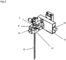
- Fig. 2 shows an enlarged view of the filling needle system 3.
- the filling needle system 3 comprises a combined filling and inerting needle 12.
- the filling needle system 3 is fixed in a terminal block 13 and can be assembled outside of the filling device 1.
- the clamping block 13 can be attached to the adjusting unit (in FIG Fig. 2 not shown) are attached.
- the assembly of the Grenadelsystems 3 in the terminal block 13 is carried out in an advantageous manner by means of clamp connections, so that a quick installation, as well as de-assembly is possible.
- the Grenadelsystem 3 can also via Have screws 14 for fine adjustment of the filling needle system 3 on the adjustment, so that the position of the combined filling and inerting needle 12 is achieved in the opening of a container. Due to the fine adjustment, preferably the filling needle system 3 and / or the clamping block 13 can be moved horizontally and / or vertically on the adjusting unit.
- Z 1 and Z 4 are preferably selected such that, if they do not represent a single bond, they are not linked together by two O atoms.
- the liquid-crystal mixtures used from the mesogenic individual substances of the formula I may additionally also contain one or more polymerisable compounds, so-called reactive mesogens (RMs), for example as described in US Pat US 6,861,107 disclosed, in concentrations of preferably 0.12 to 5 wt.%, Particularly preferably 0.2 to 2%, based on the mixture.
- RMs reactive mesogens
- Such mixtures can be used for so-called polymer stabilized VA (PS-VA) modes, negative IPS (PS-IPS) or negative FFS (PS-FFS) modes, in which a polymerization of the reactive mesogens in the liquid-crystalline mixture is to take place become.
- PS-VA polymer stabilized VA
- PS-IPS negative IPS
- PS-FFS negative FFS
- the polymerizable compounds may have one polymerizable group (monoreactive) or two or more (di- or multi-reactive), preferably two polymerizable groups.
- mesogenic group is known to the person skilled in the art and described in the literature, and means a group which, by the anisotropy of its attractive and repulsive interactions, contributes substantially to producing a liquid crystal (FK) phase in low molecular weight or polymeric substances.
- Compounds containing mesogenic groups may not necessarily have an FK phase themselves. It is also possible that mesogenic compounds show FK phase behavior only after mixing with other compounds and / or after polymerization. Typical mesogenic groups are, for example, rigid rod-shaped or disc-shaped units.
- spacer or "spacer group”, also referred to hereafter as “Sp”, is known to the person skilled in the art and described in the literature, see, for example Pure Appl. Chem. 73 (5), 888 (2001 ) and C. Tschierske, G. Pelzl, S. Diele, Angew. Chem.
- spacer refers to a flexible group linking the mesogenic group and the polymerizable group (s) in a polymerizable mesogenic compound ("RM")
- RM polymerizable mesogenic compound
- Sp is a single bond or a 1-16 C alkylene, wherein one or more CH 2 groups may be replaced by -O-, -CO-, -COO- or -OCO- so that not two O atoms directly connected to each other.
- organic group means a carbon or hydrocarbon group.
- carbon group means a monovalent or polyvalent organic group containing at least one carbon atom, which either contains no further atoms (such as -C ⁇ C-), or optionally one or more further atoms such as N, O, S, Contains P, Si, Se, As, Te or Ge (eg carbonyl, etc.).
- Hydrocarbon group means a carbon group which additionally contains one or more H atoms and optionally one or more heteroatoms such as, for example, N, O, S, P, Si, Se, As, Te or Ge.
- Halogen means F, Cl, Br or I.
- alkyl also include polyvalent groups, for example, alkylene, arylene, heteroarylene, etc.
- alkyl in this application includes straight-chain and branched alkyl groups of 1-7 carbon atoms, especially the straight-chain ones Groups methyl, ethyl, propyl, butyl, pentyl, hexyl and heptyl. Groups of 1-6 carbon atoms are generally preferred.
- alkenyl in this application encompasses straight-chain and branched alkenyl groups having 2-7 carbon atoms, in particular the straight-chain groups.
- Preferred alkenyl groups are C 2 -C 7 -1E-alkenyl, C 4 -C 7 3E-alkenyl, C 5 -C 7 -alkenyl, C 6 -C 7 -5-alkenyl and C 7 -6-alkenyl, in particular C 2 -C 7 -1E-alkenyl, C 4 -C 7 -EE-alkenyl and C 5 -C 7 -alkenyl.
- alkenyl groups are vinyl, 1E-propenyl, 1E-butenyl, 1E-pentenyl, 1E-hexenyl, 1E-heptenyl, 3-butenyl, 3E-pentenyl, 3E-hexenyl, 3E-heptenyl, 4-pentenyl, 4Z- Hexenyl, 4E-hexenyl, 4Z-heptenyl, 5-hexenyl, 6-heptenyl and the like. Groups of up to 5 carbon atoms are generally preferred.
- fluoroalkyl in this application includes straight-chain groups having at least one fluorine atom, preferably a terminal fluorine, i. Fluoromethyl, 2-fluoroethyl, 3-fluoropropyl, 4-fluorobutyl, 5-fluoropentyl, 6-fluorohexyl and 7-fluoroheptyl. Other positions of the fluorine are not excluded.
- aryl means an aromatic carbon group or a group derived therefrom.
- heteroaryl means “aryl” according to above definition containing one or more heteroatoms.
- the polymerizable group P is a group suitable for a polymerization reaction such as radical or ionic chain polymerization, polyaddition or polycondensation, or for a polymer-analogous reaction, for example, addition or condensation to a polymer main chain.
- a polymerization reaction such as radical or ionic chain polymerization, polyaddition or polycondensation, or for a polymer-analogous reaction, for example, addition or condensation to a polymer main chain.
- groups suitable for polymerization with ring opening for example oxetane or epoxy groups
- Typical and preferred reactive mesogens are, for example, in WO 93/22397 . EP 0 261 712 . DE 195 04 224 . WO 95/22586 . WO 97/00600 . US 5,518,652 . US 5,750,051 . US 5,770,107 and US 6,514,578 Very particularly preferred reactive mesogens are mentioned in Table E.
- the process is used to prepare a mixture consisting of organic compounds, one or more of which are preferably mesogenic, preferably liquid crystalline.
- the mesogenic compounds preferably comprise one or more liquid crystalline compounds.
- the process product is a homogeneous, liquid-crystalline mixture.
- the process also comprises the preparation of mixtures which consist of organic substances in the homogeneous liquid phase and contain therein insoluble additives (eg small particles).
- the method can thus also be used for the preparation of suspension-type or emulsion-type mixtures based on a continuous homogeneous organic phase.
- such process variants are generally less preferred.
- the liquid crystal phases according to the invention can be modified in such a way that they can be used in every type of LCD display known to date, e.g. From ECB, VAN, IPS, FFS, TN, TN-TFT, STN, OCB, GH, PS-IPS, PS-FFS, PS-VA or ASM-VA displays can be used.
- the liquid-crystal mixtures may also contain further additives known to the person skilled in the art and described in the literature, such as, for example, US Pat.
- UV stabilizers such as Tinuvin® Fa. Ciba, antioxidants, radical scavengers, nanoparticles, microparticles, one or more dopants, etc. included.
- 0-15% pleochroic dyes may be added, further conductive salts, preferably ethyldimethyldodecylammonium 4-hexoxybenzoate, tetrabutylammonium tetraphenylboranate or complex salts of crown ethers (cf., for example Haller et al., Mol. Cryst. Liq.
- Suitable stabilizers and dopants which can be added together with the compounds of the formula I to the mixing vessel in the preparation of the liquid-crystal mixtures are mentioned below in Tables C and D.
- 1,4-cyclohexylene rings and 1,4-phenylene rings are represented as follows:
- the cyclohexylene rings are trans-1,4-cyclohexylene rings.
- liquid-crystalline mixtures which, in addition to one or more compounds of the formula I, contain at least one, two, three, four or more compounds from Table B.
- Table C ⁇ / u> ⁇ /b>
- possible dopants are given, which are usually added to the liquid-crystalline mixtures.
- the mixtures contain 0-10 wt.%, In particular 0.01-5 wt.% And particularly preferably 0.01-3 wt.% Of dopants.
- Suitable polymerizable compounds (reactive mesogens) for use in the mixtures according to the invention are mentioned below in Table E: ⁇ b> ⁇ u> Table E ⁇ / u> ⁇ /b> Table E summarizes example compounds which can preferably be used in the liquid-crystalline mixtures as reactive mesogenic compounds. If the liquid-crystalline mixtures contain one or more reactive compounds, they are preferably used in amounts of 0.01-5% by weight.
- an initiator or a mixture of two or more initiators must be added for the polymerization. The initiator or the initiator mixture is preferably added in amounts of 0.001-2% by weight, based on the mixture. A suitable initiator is z. B.
- liquid-crystalline mixtures contain one or more compounds selected from the group of the compounds of Table E.
- a liquid crystalline mixture, preferably for PS-VA applications, of the composition CCH-35 9.47% CCH 501 4.99% CCY-2-1 9.47% CCY-3-1 10.47% CCY-3-O2 10.47% CCY-5-O2 9.47% CPY-2-O2 11.96% CY-3-O4 8.97% CY-5-O4 10.97% RM-1 0.30% PCH-53 13.46% is determined according to the in Fig. 1 and Fig. 2 bottling described in a container.
- a liquid crystalline mixture preferably for PS-VA applications, of the composition BCH-32 7.48% CCH-23 21.93% CCH-34 3.49% CCY-3-O3 6.98% CCY-4-O2 7.98% CPY-2-O2 10.97% CPY-3-O2 10.97% CY-3-O2 15.45% RM-1 0.30% PCH-301 12.46% PCH-302 1.99% is determined according to the in Fig. 1 and Fig. 2 bottling described in a container.
- a liquid crystalline mixture preferably for PS-VA applications, of the composition CC-3-V1 8.97% CCH-23 12.96% CCH-34 6.23% CCH-35 7.73% CCP 3-1 3.49% CCY-3-O2 12.21% CPY-2-O2 6.73% CPY-3-O2 11.96% CY-3-O2 11.47% RM-1 0.30% PP 1-2V1 4.24% PY-3-02 13.71% is determined according to the in Fig. 1 and Fig. 2 bottling described in a container.
- a liquid crystalline mixture, preferably for TN-TFT applications, of the composition CBC 33 3.50% CC-3-V 38.00% CC-3-V1 10.00% CCP-V-1 3.00% CCP-V2-1 9.00% PGP-2-3 5.00% PGP-2-4 5.00% PGU-2-F 8.00% PGU-3-F 9.00% PUQU-3-F 9.50% is determined according to the in Fig. 1 and Fig. 2 bottling described in a container.
- a liquid crystalline mixture, preferably for IPS or FFS applications, of the composition APUQU-2-F 5.00% APUQU-3-F 7.50% BCH 3F.FF 7.00% CC-3-V 40.50% CC-3-V1 6.00% CCP-V-1 9.50% CPGU-3-OT 5.00% PGP-2-3 6.00% PGP-2-4 6.00% PPGU-3-F 0.50% PUQU-3-F 7.00% is determined according to the in Fig. 1 and Fig. 2 bottling described in a container.
- a liquid crystalline mixture, preferably for VA applications, of the composition BCH-32 6.00% CCH-23 18.00% CCH-34 8.00% CCP 3-1 12.00% CCP 3-3 3.00% CCY-3-02 6.00% CPY-2-O2 6.00% CPY-3-O2 7.00% CY-3-02 14.00% CY-3-O4 8.00% CY-5-O2 9.00% PYP 2-3 3.00% is determined according to the in Fig. 1 and Fig. 2 bottling described in a container.
- a liquid crystalline mixture, preferably for VA applications, of the composition CC-3-V 29.50% PP-1-3 11.00% PY-3-O2 12.00% CCP 3-1 9.50% CCOY-2-O2 18.00% CCOY-3-O2 13.00% GPP 5-2 7.00% is determined according to the in Fig. 1 and Fig. 2 bottling described in a container.
- the mixing examples 1 to 17 may additionally contain one or more, preferably one or two, stabilizer (s), and / or a dopant from Tables C and D.
- liquid-crystal mixtures according to Examples 18-168 are prepared analogously in accordance with the method described in Fig. 1 and Fig. 2 bottling described in a container.
- Example 22 The mixture from Example 22 is additionally admixed with 0.001% Irganox® 1076 (octadecyl-3- (3,5-di-tert-butyl-4-hydroxyphenyl) propionate, BASF) and 0.45% RM-1.
- Irganox® 1076 octadecyl-3- (3,5-di-tert-butyl-4-hydroxyphenyl) propionate, BASF
- Example 24 The mixture from Example 24 is additionally with 0.04% and 0.01% stabilized.
- Example 25 The mixture from Example 25 is additionally with 0.04% and 0.01% stabilized.
- Example 26 The mixture of Example 26 is additionally with 0.04% and 0.015% stabilized.
- Example 27 The mixture from Example 27 is additionally with 0.04% and 0.02% stabilized.
- the mixture from Example 28 is additionally with 0.04% and 0.015% stabilized.
- the mixture from Example 29 is additionally with 0.01% stabilized.
- Example 35 The mixture of Example 35 is additionally 0.3% RM-1 added.
- Example 36 The mixture from Example 36 is additionally admixed with 0.001% Irganox® 1076 (octadecyl-3- (3,5-di-tert-butyl-4-hydroxyphenyl) propionate, BASF) and 0.3% RM-1.
- Irganox® 1076 octadecyl-3- (3,5-di-tert-butyl-4-hydroxyphenyl) propionate, BASF
- the mixture from Example 40 is additionally with 0.01% stabilized.
- the mixture from Example 41 is additionally with 0.3% stabilized.
- Example 42 The mixture from Example 42 is additionally admixed with 0.001% Irganox® 1076 (octadecyl-3- (3,5-di-tert-butyl-4-hydroxyphenyl) propionate, BASF) and 0.45% RM-1.
- Irganox® 1076 octadecyl-3- (3,5-di-tert-butyl-4-hydroxyphenyl) propionate, BASF
- Example 64 The mixture from Example 64 is additionally with 0.01% stabilized.
- Example 78 The mixture from Example 78 is additionally with 0.01% stabilized.
- Example 78 The mixture from Example 78 is additionally with 0.01% stabilized.
- Example 101 The mixture from Example 101 is additionally admixed with 0.001% Irganox® 1076 (octadecyl-3- (3,5-di-tert-butyl-4-hydroxyphenyl) propionate, BASF) and 0.3% RM-1.
- Irganox® 1076 octadecyl-3- (3,5-di-tert-butyl-4-hydroxyphenyl) propionate, BASF
- Example 102 The mixture from Example 102 is additionally with 0.01% stabilized.
- Example 106 The mixture from Example 106 is additionally mixed with 0.25% RM-35. offset and in addition with 0.025% stabilized.
- Example 107 The mixture from Example 107 is additionally with 0.03% stabilized.
- Example 107 The mixture from Example 107 is additionally with 0.03% stabilized.
- CC-3-V1 10.25% CCH-23 18.50% CCH-35 6.75% CCP 3-1 6.00% CCY-3-1 2.50% CCY-3-O2 12.00% CPY-2-O2 6.00% CPY-3-O2 9.75% CY-3-O2 11.50% PP 1-2V1 3.75% PY-3-O2 13.00% Clearing point [° C]: 74.7 ⁇ n [589 nm, 20 ° C]: .1027 ⁇ [1 kHz, 20 ° C]: -3.1 ⁇ ⁇ [1 kHz, 20 ° C]: 3.4 ⁇ ⁇ [1 kHz, 20 ° C]: 6.5 ⁇ 1 [mPa.s, 20 ° C]: 104 K 1 [pN, 20 ° C]: 15.4 K 3 [pN, 20 ° C]: 16.8 V 0 [20 ° C, V]: 2.46
- Example 101 The mixture from Example 101 is additionally admixed with 0.01% Irganox® 1076 (octadecyl-3- (3,5-di-tert-butyl-4-hydroxyphenyl) propionate, BASF) and 0.3% RM-1 added.
- Irganox® 1076 octadecyl-3- (3,5-di-tert-butyl-4-hydroxyphenyl) propionate, BASF
- Example 117 The mixture from Example 117 is additionally with 0.04% and 0.015% stabilized.
- Example 118 The mixture from Example 118 is additionally with 0.04% and 0.015% stabilized.
- Example 119 The mixture of Example 119 is supplemented with 0.25% RM-41 added.
- Example 119 The mixture of Example 119 is supplemented with 0.3% RM-17 added.
- Example 126 The mixture from Example 126 is additionally with 0.015% 0.015% stabilized.
- Example 131 The mixture from Example 131 is additionally with 0.25% RM-41 and 0.25% RM-35 added.
- Example 132 The mixture from Example 132 is additionally with 0.04% and 0.02% stabilized.
- Example 133 The mixture from Example 133 is additionally with 0.25% RM-41 added.
- Example 134 The mixture from Example 134 is additionally with 0.2% RM-1 added.
- Example 138 The mixture from Example 138 is additionally with 0.04% stabilized.
- Example 139 The mixture from Example 139 is additionally with 0.04% stabilized.
- Example 143 The mixture from Example 143 is additionally with 0.25% RM-35 added.
- Example 144 The mixture from Example 144 is additionally treated with 0.001% Irganox® 1076 (octadecyl-3- (3,5-di-tert-butyl-4-hydroxyphenyl) propionate, BASF) and additionally with 0.4% RM-8 added.
- Irganox® 1076 octadecyl-3- (3,5-di-tert-butyl-4-hydroxyphenyl) propionate, BASF
- Example 147 The mixture from Example 147 is additionally with 0.3% RM-1 added.
- Example 148 The mixture from Example 148 is additionally with 0.04% and 0.015% stabilized.
- Example 152 The mixture from Example 152 is additionally with 0.04% and 0.02% stabilized.
- Example 153 The mixture from Example 153 is additionally with 10% RM-82 added.
- Example 154 The mixture from Example 154 is additionally with 0.04% and 0.02% stabilized.
- CC-3-V 34.00% CCPC-33 1.00% CCY-3-1 4.00% CCY-3-O2 10.00% CCY-4-O2 9.50% CPY-2-O2 9.00% CPY-3-O2 10.00% PP 1-2V1 1.50% PY-3-O2 10.00% PYP 2-3 6.00% Y-4O-O4 5.00% Clearing point [° C]: 79.7 ⁇ n [589 nm, 20 ° C]: .1095 ⁇ [1 kHz, 20 ° C]: -3.5 ⁇ ⁇ [1 kHz, 20 ° C]: 3.7 ⁇ ⁇ [1 kHz, 20 ° C]: 7.2 ⁇ 1 [mPa.s, 20 ° C]: 105 K 1 [pN, 20 ° C]: 14.0
- Example 155 The mixture from Example 155 is additionally with 0.04% and 0.02% stabilized.
- Example 157 The mixture from Example 157 is additionally with 0.015% stabilized.
- Example 158 The mixture from Example 158 is additionally with 0.015% stabilized.
- Example 161 The mixture from Example 161 is additionally with 0.008% stabilized.
- Example 163 The mixture of Example 163 is supplemented with 0.25% RM-41 added.
- Example 168 The mixture from Example 168 is additionally with 0.03% stabilized and with 0.4% RM-41 added.
Landscapes
- Engineering & Computer Science (AREA)
- Mechanical Engineering (AREA)
- Chemical & Material Sciences (AREA)
- Dispersion Chemistry (AREA)
- Basic Packing Technique (AREA)
- Liquid Crystal Substances (AREA)
Description
- Die Erfindung beschreibt eine Abfüllvorrichtung zur Abfüllung eines Fluids, insbesondere einer Flüssigkristallmischung, in mindestens einen Behälter und deren Verwendung zur Abfüllung einer Flüssigkristallmischung.
- Es sind verschiedene Abfüllvorrichtungen oder Abfüllmaschinen bekannt, mit denen eine dosierbare Fluidmenge in einen Behälter eingebracht werden kann. Bei dem Fluid kann es sich beispielsweise um flüssige oder fließfähige chemische Rohstoffe oder um Endprodukte handeln, die in der chemischen oder pharmazeutischen Industrie verwendet werden. Das Fluid kann auch ein flüssiges Nahrungsmittel oder eine flüssige Komponente für die Zubereitung von Nahrungsmitteln sein.
- Das Fluid kann mit einem Füllnadelsystem in den Behälter eingebracht werden. Über ein Wägesystem kann eine zuverlässige Dosierung während des Befüllungsvorgangs gewährleistet werden.
- Geeignete Behälter, die im Rahmen einer industriellen Nutzung eingesetzt werden, sind üblicherweise Fässer, Kanister oder Flaschen, die aus Kunststoff, aus Metall oder aus Glas hergestellt sind. Derartige Behälter dienen zum Transportieren oder Lagern der in den Behälter eingefüllten Flüssigkeit. Hierbei sind beispielsweise sogenannte Rundläufer bekannt, bei denen zu befüllende Kleinbehälter automatisch in eine rotierende Fördereinrichtung zugeführt werden und in der Abfüllmaschine mit der gewünschten Flüssigkeit bzw. dem vorgegebenen Fluid gefüllt werden.
- Die Fluide werden üblicherweise mittels einer Pumpe aus einem Fluidreservoir, zum Beispiel aus einem weiteren Behälter, in den zu befüllenden Behälter gepumpt. Hierbei können sich die zu befüllenden Behälter hinsichtlich ihrer Größe und Form unterscheiden, so dass regelmäßig eine Anpassung der Abfüllmaschine an den im Einzelfall zu befüllenden Behälter notwendig ist. Dabei wird es als nachteilig empfunden, dass jede Änderung der Behältergröße eine Umrüstung der Abfülleinrichtung erforderlich werden lässt.
- Aus der Praxis ist bekannt, dass ein Einfüllstutzen der Abfüllvorrichtung, der zur Befüllung der Behälter verwendet wird, axial verlagerbar ist und in Abhängigkeit von der Behältergröße ausgefahren oder eingefahren wird. Die Länge des in den Behälter ragenden Abschnitts kann verändert und an jeweils andere Behältergrößen angepasst werden. Trotz der Verstellmöglichkeit für die Länge des Einfüllstutzens ist die Verwendung einer derartigen Abfüllmaschine beschränkt, da eine Kalibrierung der Abfüllgeschwindigkeit erfolgen muss und außerdem die Behälter manuell positioniert werden müssen. Für Behälter, die einen unterschiedlichen Durchmesser der für die Befüllung der Flüssigkeit vorgesehenen Öffnung aufweisen, muss entweder die Behälterposition gesondert vorgegeben werden, wodurch ein zusätzlicher Handhabungsaufwand anfällt, oder aber eine gesonderte, an die betreffenden Behälter angepasste Abfüllmaschine verwendet werden.
- In
US 4,211,263 wird eine Abfüllvorrichtung beschrieben, die unter anderem eine Waage, einen Aufnahmetisch, eine Füllnadel und eine Verstelleinheit aufweist, wobei der Aufnahmetisch mit der Waage verbunden ist und die Füllnadel durch die Verstelleinheit vertikal bewegbar ist. - Besonders bei der Abfüllung von Flüssigkristallmischungen werden hohe Anforderungen an die Abfüllmaschine, beziehungsweise den Abfüllvorgang gestellt, wie zum Beispiel Reinraumumgebungsbedingungen. Vor der Befüllung der Behälter mit Flüssigkristallmischungen müssen die zu befüllenden Behälter in der Regel inertisiert werden, was üblicherweise vor einer Anordnung der Behälter in einer Befüllposition erfolgt und anschließend eine Verlagerung der Behälter von einer Inertisierungsposition zur Befüllposition nach sich zieht.
- Es wird deshalb als eine Aufgabe der vorliegenden Erfindung angesehen, eine Abfüllmaschine zur Befüllung von Flüssigkeiten in einen Behälter so auszugestalten, dass die Abfüllmaschine mit möglichst geringem Aufwand an verschiedene Behälter angepasst werden kann und gegebenenfalls Möglichkeiten zur Inertisierung bietet.
- Diese Aufgabe wird erfindungsgemäß dadurch gelöst, dass eine Abfüllvorrichtung zur Abfüllung eines Fluids in mindestens einen Behälter bereitgestellt wird, wobei die Abfüllvorrichtung zumindest ein Wägesystem und ein Füllnadelsystem aufweist, wobei das Wägesystem mindestens eine an einen Behälterdurchmesser anpassbare Positioniervorrichtung für Behälter aufweist, wobei das Wägesystem auf einem mit einer Lineareinheit vertikal verfahrbaren Aufnahmetisch angeordnet ist und wobei das Füllnadelsystem an einer Verstelleinheit in einer in axialer Richtung beabstandeten Positionen oberhalb der Positioniervorrichtung angeordnet ist.
- Im Rahmen der vorliegenden Erfindung werden unter dem Begriff Fluid alle fließfähigen anorganischen, organischen oder biologischen Systeme oder Gemische, beispielsweise echte oder kolloidale Lösungen, Suspensionen, Emulsionen, Schmelzen, Dispersionen, Flüssig/Gas-Dispersionen oder Mischungen daraus, verstanden. Insbesondere flüssigkristalline Mischungen sowie isotop flüssige Mischungen sind im Sinne der Erfindung als Fluide zu verstehen.
- Die Abfüllvorrichtung kann vorteilhafterweise zur Abfüllung einer Flüssigkristallmischung in mindestens einen Behälter verwendet werden, wobei die Abfüllung vorzugsweise in einem Reinraum erfolgt. Die Vorrichtung ist auf Grund ihrer vorteilhaften Bauart für den Einsatz in Reinräumen geeignet. Dies hat sich als überaus positiv herausgestellt, da durch die erfindungsgemäße Ausgestaltung der Abfüllvorrichtung die Notwendigkeit entfällt, die Abfüllvorrichtung bei einem Wechsel der Behälter umzurüsten, wodurch Kosten und Arbeitsaufwand eingespart werden können. Insbesondere die Möglichkeit, dass eine Inertisierung und eine Befüllung eines Behälters mit der Abfüllvorrichtung erfolgen können, ohne dass größere manuelle Eingriffe oder eine Verlagerung des Behälters oder ein aufwendiger Umrüstvorgang erforderlich werden, hat sich als vorteilhaft für die Verwendung der Abfüllvorrichtung vor allem in einem Reinraum herausgestellt. Außerdem kann die hohe Qualität und Reinheit des abgefüllten Fluids insbesondere im Falle einer Flüssigkristallmischung beibehalten werden.
- Es wird eine Abfüllvorrichtung bereitgestellt, mit der eine hohe Abfüllgenauigkeit erreicht wird. Der Abfüllvorgang kann durch eine hochgenaue Waage überwacht werden. Das die Waage beinhaltende Wägesystem weist mindestens eine bevorzugt ringförmig ausgestaltete Positioniervorrichtung für mindestens einen Behälter auf. Somit kann nicht nur der leere Behälter gewogen, sondern auch der Abfüllvorgang selbst und die während des Abfüllvorgangs zudosierte Fluidmenge überwacht. Während des Abfüllvorgangs wird vorzugsweise durch einen in dem Wägesystem integrierten Prozessrechner in festlegbaren Intervallen der Volumenstrom der einzufüllenden Flüssigkeit überwacht und dieser ermittelte Ist-Wert mit einem Soll-Wert abgeglichen. Der Volumenstrom kann bei Bedarf manuell oder automatisch erhöht oder erniedrigt werden. Die Änderung des Volumenstroms kann über ein Membranventil erfolgen, welches dem Füllnadelsystem vorgeschaltet ist. Denkbar sind auch sonstige regelbare oder steuerbare Ventile.
- In einer bevorzugten Ausführungsform der Vorrichtung ist eine Bedienereinheit, zum Beispiel ein Touchscreen-Monitor mit einem Lesegerät, mit der Abfüllvorrichtung verbunden. Über das Lesegerät, welches beispielsweise als Barcode-Scanner ausgestaltet ist, kann eine Information bzw. ein Barcode auf einem zu befüllenden Behälter oder auf einem Vorratsbehälter des abzufüllenden Fluids eingelesen werden. Diese Information wird mit einer Datenbank abgeglichen, woraufhin automatisiert abfüllvorgangspezifische, das heißt, behälterspezifische oder produktspezifische Einstellungen an der Abfüllvorrichtung vorgenommen werden können, so dass ein individueller Abfüllvorgang für unterschiedliche Fluide oder für unterschiedliche Behälter gewährleistet werden kann.
- Um eine Anpassung an die unterschiedlichen Behältergrößen, beziehungsweise Gebindegrößen zu ermöglichen ist das Wägesystem mit der Positioniervorrichtung auf einem mit einer Lineareinheit vertikal verfahrbaren Aufnahmetisch angeordnet, so dass in Abhängigkeit von dem zu befüllenden Behälter, das heißt in Abhängigkeit von dessen Volumen oder Größe, eine Anpassung der Position des Wägesystems und damit des Behälters relativ zu dem Füllnadelsystem vorgenommen werden kann. Der Aufnahmetisch wird von einer Maschinensteuerung der Lineareinheit automatisch auf die für die Abfüllung des Behälters benötigte Höhe gefahren. Eine zusätzliche Detektion des leeren Behälters über das Eigengewicht kann Fehlfunktionen der Abfüllvorrichtung verhindern.
- Es kann auch vorteilhaft sein, dass die Abfüllvorrichtung zwei oder mehr Wägesysteme umfasst, wobei die Wägesysteme jeweils auf einem mit jeweils einer Lineareinheit vertikal verfahrbaren gesonderten Aufnahmetisch angeordnet sind. Die Aufnahmetische sind separat steuerbar, so dass mittels der Abfüllvorrichtung zwei Behälter, insbesondere zwei Behälter unterschiedlicher Größe gleichzeitig befüllt werden können.
- Es ist ebenfalls möglich und für bestimmte Anwendungsfälle vorteilhaft, zwei oder mehr Wägesysteme auf einem gemeinsamen Aufnahmetisch anzuordnen, falls die Abfüllvorrichtung überwiegend zur Befüllung einer einzigen Behältergröße verwendet wird.
- In einer besonders vorteilhaften Auführungsform weist die Abfüllvorrichtung zwei Wägesysteme auf, wobei die beiden Wägesysteme jeweils auf einem mit jeweils einer Lineareinheit vertikal verfahrbaren Aufnahmetisch montiert sind.
- Das Wägesystem weist bevorzugt mindestens eine ringförmig ausgestaltete Positioniervorrichtung für Behälter auf. Im Falle von zwei Wägesystemen oder mehr ist zweckmäßigerweise vorgesehen, dass jedes Wägesystem mit jeweils einer Positioniervorrichtung auf dem mindestens einen verfahrbaren Aufnahmetisch angeordnet ist. Das Wägesystem kann zudem eine universelle Positioniervorrichtung aufweisen, mit welcher die Behälter sicher zentriert und positioniert werden können. Dies hat sich als vorteilhaft herausgestellt, da hierdurch die Füllnadel reproduzierbar in der Öffnung der Behälter positioniert werden kann. Diese universelle Anpassungsfähigkeit der Positioniervorrichtung wird dadurch bereitgestellt, dass die Positioniervorrichtung aus mehreren ringförmigen Ausbuchtungen besteht und jede Ausbuchtung für eine definierte Behältergröße vorgesehen oder genormt ist. Auch Mittel zum Spannen können zur Positionierung der Behälter genutzt werden.
- Bei den für eine Verwendung mit der Abfüllvorrichtung besonders geeigneten Behältern handelt es sich um Glasflaschen in den Größen 0,1 - 0,5 l und 1 l, sowie um Stahlbehälter in der Größe 10 l. Diese Anpassungsfähigkeit der Positioniervorrichtung garantiert eine universelle Einsetzbarkeit der Vorrichtung und ist als wesentlicher Vorteil gegenüber der im Stand der Technik bekannten Abfüllvorrichtungen anzusehen. Selbstverständlich kann die Abfüllvorrichtung jederzeit um weitere Positioniervorrichtungen, die auf weitere Behältergrößen genormt sind, erweitert werden. Vorteilhafterweise sind die Positioniervorrichtungen auf oder an dem Wägesystem mit einer kraftschlüssigen oder formschlüssigen Verbindung festlegbar, so dass ein schneller Austausch möglich ist.
- Es hat sich als vorteilhaft erwiesen, wenn die Abfüllvorrichtung, insbesondere das Wägesystem und der Volumenstrom an die abzufüllende Flüssigkeit und die Behälter abgestimmt werden kann. Hierdurch ist eine produktspezifische Abfüllung durch eine Anpassung der Füllparameter über eine Software der Vorrichtungssteuerung möglich. Differierende Eigenschaften der Fluide, insbesondere verschiedener Flüssigkristallmischungen erfordern auch unterschiedliche Abfüllparameter. Die optimalen Abfüllparameter können in geeigneter Weise vorab in Versuchen ermittelt und in einer Datenbank hinterlegt werden. Bei einer Initialisierung der Vorrichtung können die produktspezifischen Daten über ein Eingabe- oder Lesegerät, zum Beispiel eine Barcode-Leseeinrichtung eingelesen und anhand eines Barcodes auf den Chargenbegleitpapieren identifiziert werden. Eine Feinjustierung der Parameter kann zudem auch von Hand möglich sein.
- Weiterhin ist der Einsatz einer Pumpe vorteilhaft, deren Ansteuerung von der Abfüllvorrichtung übernommen werden kann. Über die Datenbank werden bevorzugt die entsprechenden Parameter abgerufen und zum Beispiel der Volumenstrom entsprechend reguliert. Die Abfüllvorrichtung kann auch vorteilhafterweise eine Druckregelung eines Vorlagebehälters und damit eine Medienförderung sicherstellen.
- Das Füllnadelsystem ist bevorzugt an einer horizontal verfahrbaren Verstelleinheit in axialer Richtung oberhalb der Positioniervorrichtung beabstandet angeordnet. Die Abfüllung erfolgt bevorzugt softwaregesteuert in den Schritten Grob-, Mittel-, und Feinstrom. Hierdurch kann die Dauer des Abfüllvorgangs minimiert werden.
- Gemäß einer vorteilhaften Ausgestaltung des Erfindungsgedankens ist vorgesehen, dass das Füllnadelsystem eine kombinierte Füll- und Inertisierungsnadel umfasst. Zudem können die Durchmesser der kombinierten Füll- und Inertisierungsnadel hinsichtlich des zu erwartenden Füllstroms in Versuchen optimiert worden sein. Vor der Abfüllung wird der Behälter vorzugsweise mit einem Edelgas inertisiert.
- Das Füllnadelsystem kann zu diesem Zweck zusätzlich zu der Füllnadel ein zweites seitlich angeschweißtes, oder in einem anderen Ausführungsfall ein koaxial über der Füllnadel angebrachtes Rohr aufweisen, das im Sinne der Erfindung ebenfalls als Nadel bezeichnet wird. Das heißt, das Füllnadelsystem umfasst vorzugsweise eine erste Nadel für die Inertisierung und eine zweite Nadel für die Befüllung. Durch die Kombination einer Inertisierungsnadel und einer Füllnadel kann der Inertisierungs- sowie der Abfüllvorgang in einer Position, nämlich in der erfindungsgemäßen Abfüllvorrichtung vorgenommen werden, ohne dass eine Verlagerung des Behälters notwendig ist. Das Inertisierungsrohr, beziehungsweise die Inertisierungsnadel kann vorteilhafterweise in einem vorderen Bereich etwas verjüngt sein, um das Einführen der Nadel in Glasflaschen mit engen Mündungen zu ermöglichen.
- In einer bevorzugten Ausführungsform der Vorrichtung ist das Füllnadelsystem in einem aus einer Verstelleinheit entnehmbaren Klemmblock angeordnet. Das gesamte Füllnadelsystem wird vorzugsweise in einen Klemmblock montiert und kann so außerhalb der Vorrichtung vorbereitet und zusammengebaut werden. Der Klemmblock kann mit dem Fachmann bekannten Befestigungsmittel, insbesondere Schrauben, auf der Verstelleinheit angebracht und fixiert werden. Die Montage des Füllnadelsystems an dem Klemmblock erfolgt bevorzugt mit Clamp-Anschlüssen, insbesondere nach den DIN Normen 32676, 11851, 11864 und 11853. Hierdurch kann eine schnelle Montage sowie Demontage gewährleistet werden.
- Komponenten des Füllnadelsystems, die während des Befüllungsvorgangs mit dem jeweils verwendeten Fluid in Kontakt kommen können, bestehen bevorzugt aus Edelstahl und/oder Polytetrafluorethylen (PTFE). Es kann jedoch je nach vorgesehenem Verwendungszweck ebenfalls zweckmäßig sein, sonstige Metalle oder Kunststoffe zu verwenden. Kunststoffe bezeichnen insbesondere Materialien, deren wesentliche Bestandteile aus solchen makromolekularen organischen Verbindungen bestehen, die synthetisch oder durch Abwandeln von Naturprodukten entstehen. Zu den Kunststoffen gehören insbesondere auch die Kautschuke und die Chemiefasern. Für die vorteilhafte Ausführungsform können Kunststoffe aus der Gruppe abgewandelte Naturstoffe, synthetische Kunststoffe (Polykondensate, Polymerisate, Polyaddukte), Duroplaste, und/oder ungesättigte Polyesterharze, umfassend Cellulosenitrat, Celluloseacetat, Cellulosemischester, Celluloseether, Polyamid, Polycarbonat, Polyester, Polyphenylenoxid, Polysulfon, Polyvinylacetal, Polyethylen, Polypropylen, Poly-1-buten, Poly-4-methyl-1-penten, lonomere, Polyvinylchlorid, Polyvinylidenchlorid, Polymethyl-methacrylat, Polyacrylnitril, Polystyrol, Polyacetal, Fluor-Kunststoffe, Polyvinylalkohol, Polyvinylacetat, Poly-p-xylylen, lineare Polyurethane, chlorierte Polyether, Casein-Kunststoffe, vernetzte Polyurethane, Silicon, Polyimid, und/oder Polybenzimidazol verwendet werden.
- Weiterhin kann es vorteilhaft sein, wenn die Komponenten des Füllnadelsystems aus Metall, insbesondere aus Edelstahl gefertigt sind. Der Edelstahl ist gegen Wasser, Wasserdampf, Luftfeuchtigkeit, Speisesäuren sowie gegen schwache organische und anorganische Säuren beständig und bietet der Füllnadel einen guten Schutz gegenüber vielen verschiedenen Fluiden. Selbstverständlich kann es auch vorteilhaft sein, das Füllnadelsystem aus einer Kombination aus Metall und Kunststoff zu fertigen.
- Der Klemmblock des Füllnadelsystems wird an der Verstelleinheit befestigt, wobei die Verstelleinheit und insbesondere der Klemmblock mittels geeigneten Mitteln zur Feinjustierung zumindest horizontal verfahrbar ist. Dadurch lassen sich leichte Ungenauigkeiten der Nadelgeometrie verschiedener Nadeln ausgleichen. Die Justierung kann vorteilhafterweise per Hand mit Verstellschrauben erfolgen, so dass eine Feinjustierung in Richtung der X- und Z-Achse des Füllnadelsystems möglich ist.
- Die Abfüllvorrichtung weist in einer bevorzugten Ausführungsform ein Tropfenfängersystem auf, wobei das an einem Schwenkarm befestigte und ein Gefäß umfassende Tropfenfängersystem unter das Füllnadelsystem schwenkbar ist, falls sich kein Behälter in der Positioniervorrichtung befindet oder der Befüllungsvorgang beendet ist. Ein Nachtropfen von Flüssigkeit, insbesondere Flüssigkristallmischung aus der Füllnadel auf das Wägesystem kann dadurch vermieden werden.
- Die Füllnadel ist hinsichtlich ihrer Dimensionierung optimiert, so dass sie bevorzugt in die Öffnung des Behälters hineinragt. Um auch bei einer derartigen Ausgestaltung der Füllnadel ein Nachtropfen von Flüssigkeit aus dem Füllnadelsystem zu verhindern kann ein daran angepasstes Tropfenfängersystem integriert sein. Es besteht insbesondere aus einem Gefäß, insbesondere einem Auffanggefäß, welches auf einem Schwenkarm montiert ist, der nach dem Abfüllvorgang automatisch oder manuell unter das Füllnadelsystem gefahren werden kann. Das heißt, sobald der Abfüllvorgang beendet ist oder sich kein Behälter in der Positioniervorrichtung des Wägesystems befindet, kann das Gefäß unter das Füllnadelsystem geschwenkt werden. Hierdurch kann ein Nachtropfen von Flüssigkeit auf das Wägesystem zuverlässig verhindert werden.
- Vorteilhafterweise ist dem zur Steuerung des Volumenstroms verwendeten Membranventil eine Filtereinheit zur Filtration des abzufüllenden Fluids vorgeschaltet. Vor der Abfüllung wird bevorzugt die gesamte abzufüllende Flüssigkeit über eine Filtereinheit gefiltert. Eine solche Filtereinheit kann zum Beispiel seitlich an der Vorrichtung in einer entsprechenden Filterhalterung angebracht sein und einen Feinstfilter umfassen. Der Filter ist bevorzugt leicht zugänglich auf einem Schnellwechsel-Filterhalter befestigt. Vorteilhafterweise kann er vor Anbringung vorbereitet und anschließend bevorzugt über einen Clamp-Anschluss an die Filterhalterung angebracht werden.
- Um unerwünschte Effekte durch elektrostatische Aufladung der Flüssigkeit, insbesondere der Flüssigkristallmischung beim Abfüllvorgang zu vermeiden sind in einer bevorzugten Ausgestaltung der Vorrichtung seitlich, oberhalb und/oder unterhalb des Füllnadelsystems Ionisatoren verbaut und strömen das Füllnadelsystem und/oder den Abfüllbereich mit einem gerichteten Strom ionisierter Luft an. Damit lassen sich insbesondere Effekte wie ein "Vorbeilaufen" einer Flüssigkristallmischung an der Öffnung oder Mündung des zu befüllenden Behälters durch elektrostatische Aufladung weitgehend vermeiden.
- Ferner kann es vorteilhaft sein, wenn seitlich zum Füllnadelsystem Schutzwände mit einer antistatischen Beschichtung angeordnet sind. Die Schutzwände sind vorzugsweise geerdet. Durch die Schutzwände können ansonsten aufgrund des Laminarflows des abzufüllenden Fluids eventuell auftretende störende elektrostatische Effekte reduziert oder sogar vollständig vermieden werden.
- In der nachfolgenden Aufzählung sind verschiedene Merkmale und Vorteile der erfindungsgemäßen Abfüllvorrichtung zusammengefasst:
- Hohe Abfüllgenauigkeit (insbesondere -0% / +0,3 -0,03%);
- Hohe Abfüllgeschwindigkeit inklusive Inertisierung des Behälters, insbesondere 0,5 l in 30 Sekunden;
- Einsatz von Glasflaschen unterschiedlicher Abmessungen und insbesondere 10 l Behältern auf einer Vorrichtung möglich;
- Einfach zu demontierendes und zu reinigendes Füllnadelsystem;
- Inertisierung der Behälter vor der Abfüllung;
- Filtration des Abfüllmediums, insbesondere der Flüssigkeit vor der Abfüllung;
- Feinjustierung des Füllnadelsystems über die Verstelleinheit möglich;
- Integrierte Ionisatoren zur Ionisierung der Abfüllstelle zur Verringerung elektrostatischer Effekte;
- Tropfenfängersystem zur Vermeidung von Kontamination und Fehlmessungen der Vorrichtung durch abtropfende Flüssigkeit, insbesondere Flüssigkristallmischung;
- Produktspezifische Abfüllung durch Anpassung der Füllparameter über die Software der Vorrichtungssteuerung.
- Weitere vorteilhafte Ausgestaltungen werden anhand eines in der Zeichnung dargestellten Ausführungsbeispiels näher erläutert. Es zeigt:
-
Fig. 1 eine exemplarische Abbildung einer erfindungsgemäßen Abfüllvorrichtung, und -
Fig. 2 eine exemplarische Abbildung eines Füllnadelsystems für die inFig. 1 gezeigte Abfüllvorrichtung. - In
Figur 1 ist eine schematische Darstellung einer bevorzugten Abfüllvorrichtung 1 gezeigt. Die Abfüllvorrichtung 1 umfasst zwei getrennte Wägesystem 2, zwei Füllnadelsysteme 3, zwei eine an einen Behälterdurchmesser anpassbare Positioniervorrichtungen 4 und zwei Tropfenfängersysteme 5. - Die Positioniervorrichtung 4 für einen Behälter ist ringförmig ausgestaltet und weist Ausbuchtungen unterschiedlicher Größe auf, so dass Behälter mit unterschiedlichen Größen bzw. Durchmessern eingebracht und sicher in der jeweiligen Positioniervorrichtung fixiert werden können.
- Um eine vertikale Verfahrbarkeit der beiden Wägesysteme 2 zu ermöglichen sind die beiden Wägesysteme 2 auf einem mit einer Lineareinheit 6 vertikal verfahrbaren Aufnahmetisch 7 angeordnet. Mit dem gemeinsamen Aufnahmetisch 7 können die beiden Wägesysteme 2 einheitlich an unterschiedliche Behältergrößen angepasst werden, wobei eine automatische oder auch manuelle Verschiebung des Aufnahmetisches 7 erfolgen kann.
- Für den Fall, dass mehrere unterschiedlich große Behälter unabhängig voneinander und nach Möglichkeit gleichzeitig mit einem oder mehreren Fluiden befüllt werden sollen, könnte abweichend von der exemplarisch dargestellten Ausführungsvariante jedes Wägesystem 2 auf je einem zugeordneten Aufnahmetisch 7 angeordnet werden, wobei die Aufnahmetische 7 unabhängig voneinander mit jeweils einer Lineareinheit 6 vertikal verfahrbar sind. Hierdurch können die Aufnahmetische 7 in unterschiedliche Positionen gefahren werden, wodurch die Befüllung unterschiedlicher Behältergrößen möglich ist.
- Die Füllnadelsysteme 3 sind jeweils in einer in axialer Richtung beabstandeten Position oberhalb der Positioniervorrichtungen 4 an einer horizontal verfahrbaren Verstelleinheit 8 angeordnet. Hierdurch kann jedes Füllnadelsystem 3 ebenso wie das zugeordnete Wägesystem 2 an unterschiedliche Behältergrößen angepasst werden. Die Einstellung des Füllnadelsystems 3 erfolgt über eine Feinjustierung, die eine horizontale Verlagerung des Systems 3 in X-und Z-Richtung ermöglicht. Gegebenenfalls kann auch eine gleichzeitig horizontale und vertikale Verfahrbarkeit des Füllnadelsystems 3 vorgesehen sein. Es hat sich herausgestellt, dass hierdurch sichergestellt werden kann, dass das Füllnadelsystem 3 optimal in die Öffnung eines Behälters eindringt und eine effiziente und verlustfreie Befüllung möglich ist.
- Um zu verhindern, dass nach einer Befüllung eines Behälters Fluidreste aus dem Füllnadelsystem 3 auf das Wägesystem 4 tropfen, kann vorteilhafterweise nach Befüllung das an einem Schwenkarm befestigte und ein Gefäß umfassende Tropfenfängersystem 5 unter das zugeordnete Füllnadelsystem 3 geschwenkt werden. Somit kann sichergestellt werden, dass das Wägesystem 3 nicht mit Fluidresten verunreinigt und dadurch die Wägung eines aktuellen oder zukünftigen Abfüllvorgangs verfälscht wird. Selbstverständlich kann das Tropfenfängersystem 5 auch derart ausgestaltet sein, dass es automatisch unter das Füllnadelsystem 3 schwenkt, sobald bzw. falls sich kein Behälter in der Positioniervorrichtung 4 befindet.
- Vor einer Befüllung eines in der Positioniervorrichtung 4 befindlichen Behälters wird das abzufüllende Fluid vorteilhafterweise mit einer Filtereinheit 9 gereinigt. Die Filtereinheit 9, vorzugsweise ein Feinstfilter, kann in einem Filterhalter 10 seitlich an der Abfüllvorrichtung 1 angebracht sein. Die Filtereinheit 9 kann vor Beginn der Abfüllung vorbereitet werden und schnell insbesondere über Clamp-Anschlüsse in den Filterhalter 10 eingesetzt werden.
- Unterschiedliche Eigenschaften der abzufüllenden Fluide und vor allem Flüssigkristallmischungen erfordern die Anpassung der Abfüllung an die differenzierenden Eigenschaften der betreffenden Fluide. Die spezifischen Abfüllparameter wie zum Beispiel eine Einstellung des Wägesystem, die Behältergröße, eine Abfüllgeschwindigkeit und gegebenenfalls eine Ionisierung können vorab ermittelt und in einer Datenbank gespeichert werden. Bei der Initialisierung der Abfüllvorrichtung können diese Parameter zum Beispiel über einen Touchscreen-Monitor 11 in die Abfüllvorrichtung 1 eingegeben werden. Anschließend stellt die Abfüllvorrichtung 1 automatisch alle relevanten Parameter entsprechend ein. Es kann jedoch auch vorteilhaft sein, wenn die produktspezifischen Daten über ein Lesegerät, beispielsweise einen Barcode-Reader (nicht dargestellt) anhand eines Barcodes auf Chargenbegleitpapieren, auf zu befüllenden Behältern oder auf einem Vorratsbehälter des abzufüllenden Fluids eingelesen werden. Der Barcode-Reader kann somit eine vorteilhafte Ergänzung der Abfüllvorrichtung 1 sein und beispielsweise mit dem Touchscreen-Monitor 11 verbunden sein. Die Abfüllvorrichtung 1 ist in einem Schaltschrank 15 angeordnet, der auch Verschaltungen von Zu- und Ableitungen der Abfüllvorrichtung 1 beherbergt.
- Seitlich neben den Wägesystemen 2 beziehungsweise neben den Füllnadelsystemen 3 können Seitenwände 16 angeordnet sein, die eine antistatische Beschichtung aufweisen, so dass elektrostatische Aufladungen verhindert werden, die durch einen Laminarflow der abzufüllenden Flüssigkeit entstehen.
-
Fig. 2 zeigt in vergrößerter Darstellung das Füllnadelsystem 3. Das Füllnadelsystem 3 umfasst eine kombinierte Füll- und Inertisierungsnadel 12. Somit sind eine Befüllung und eine Inertisierung eines Behälters mit dem Füllnadelsystem 3 der Abfüllvorrichtung möglich, ohne das hierfür der Behälter zu einer weiteren Station transportiert werden muss. - Das Füllnadelsystem 3 ist in einem Klemmblock 13 festgelegt und kann außerhalb der Abfüllvorrichtung 1 zusammengesetzt werden. Der Klemmblock 13 kann mit Befestigungsmitteln, zum Beispiel Schrauben, an der Verstelleinheit (in
Fig. 2 nicht dargestellt) angebracht werden. Die Montage des Füllnadelsystems 3 im Klemmblock 13 erfolgt in vorteilhafter Weise mittels Clamp-Anschlüssen, so dass eine schnelle Montage, sowie De-Montage möglich ist. Das Füllnadelsystem 3 kann ferner über Schrauben 14 zur Feinjustierung des Füllnadelsystems 3 auf der Verstelleinheit verfügen, so dass die Position der kombinierten Füll- und Inertisierungsnadel 12 in der Öffnung eines Behälters erzielt wird. Durch die Feinjustierung kann bevorzugt das Füllnadelsystem 3 und/oder der Klemmblock 13 auf der Verstelleinheit horizontal und/oder vertikal verfahren werden. - Das vorangehend beschriebene Abfüllvorrichtung ist insbesondere geeignet für Flüssigkristallmischungen. Hierbei werden insbesondere Flüssigkristallmischungen enthaltend mindestens zwei organische Substanzen, vorzugsweise mesogene, insbesondere flüssigkristalline Substanzen, verwendet, wobei die organischen Substanzen vorzugsweise ausgewählt sind aus den Verbindungen der allgemeinen Formel I,

- R1 und R2
- jeweils unabhängig voneinander H, einen unsubstituierten, einen einfach durch CN oder CF3 oder mindestens einfach durch Halogen substituierten Alkylrest mit bis zu 15 C-Atomen, wobei in diesen Resten auch eine oder mehrere CH2-Gruppen durch -O-, -S-,

- Ringe A, B, C, D, E
- jeweils unabhängig voneinander
- r, s und t
- jeweils unabhängig voneinander 0, 1, 2 oder 3, wobei r + s+ t ≤ 3 ist,
- Z1-4
- jeweils unabhängig voneinander -CO-O-, -O-CO-, -CF2O-, -OCF2-, -CH2O-, -OCH2-, -CH2CH2-, -(CH2)4-, -CH=CH-CH2O-, -C2F4-, -CH2CF2-, -CF2CH2-, -CF=CF-, -CH=CF-, -CF=CH-, -CH=CH-, -C≡C- oder eine Einfachbindung, und
- L1 und L2
- jeweils unabhängig voneinander H oder F,
- Für den Fall, dass r + s + t = 0 ist, so sind Z1 und Z4 bevorzugt derart ausgewählt, dass sie, wenn sie keine Einfachbindung bedeuten, nicht über zwei O-Atome miteinander verknüpft sind.
- Die eingesetzten Flüssigkristallmischungen aus den mesogenen Einzelsubstanzen der Formel I können zusätzlich auch eine oder mehrere polymerisierbare Verbindungen, sogenannte reaktive Mesogene (RMs), beispielsweise wie in
U.S. 6,861,107 offenbart, in Konzentrationen von bevorzugt 0,12 - 5 Gew.%, besonders bevorzugt 0,2 - 2 %, bezogen auf die Mischung enthalten. Derartige Mischungen können für sogenannte Polymer Stabilized VA (PS-VA)-Modes, negativ IPS (PS-IPS)- oder negativ FFS (PS-FFS)-Modes, bei denen eine Polymerisierung der reaktiven Mesogene in der flüssigkristallinen Mischung erfolgen soll, verwendet werden. Voraussetzung hierfür ist, dass die Flüssigkristallmischung selbst keine polymerisierbaren Einzelsubstanzen, enthält. - Die polymerisierbaren mesogenen oder flüssigkristallinen Verbindungen, auch als "reaktive Mesogene" (RM) bezeichnet, sind vorzugsweise ausgewählt aus den Verbindungen der Formel II,
Ra-A1-(Z1-A2)m-Rb II
worin die einzelnen Reste folgende Bedeutung haben: - A1 und A2
- jeweils unabhängig voneinander eine aromatische, heteroaromatische, alicyclische oder heterocyclische Gruppe, vorzugsweise mit 4 bis 25 C-Atomen, welche auch annellierte Ringe enthalten kann, und welche optional durch L ein- oder mehrfach substituiert ist,
- Z1
- bei jedem Auftreten gleich oder verschieden -O-, -S-, -CO-, - CO-O-, -OCO-, -O-CO-O-, -OCH2-, -CH2O-, -SCH2-, -CH2S-, - CF2O-, -OCF2-, -CF2S-, -SCF2-, -(CH2)n-, -CF2CH2-, - CH2CF2-, -(CF2)n-, -CH=CH-, -CF=CF-, -C≡C-, -CH=CH-COO-, -OCO-CH=CH-, CR0R00 oder eine Einfachbindung,
- L, Ra und Rb
- jeweils unabhängig voneinander H, Halogen, SF5, NO2, eine Kohlenstoffgruppe oder Kohlenwasserstoffgruppe, wobei die Verbindungen mindestens einen Rest L, Ra und Rb enthalten, der eine Gruppe P-Sp- bedeutet oder enthält,
- R0 und R00
- jeweils unabhängig voneinander H oder Alkyl mit 1 bis 12 C-Atomen,
- P
- eine polymerisierbare Gruppe,
- Sp
- eine Abstandsgruppe oder eine Einfachbindung,
- m
- 0, 1, 2, 3 oder 4,
- n
- 1, 2, 3 oder 4.
- Die polymerisierbaren Verbindungen können eine polymerisierbare Gruppe (monoreaktiv) oder zwei oder mehr (di- oder multireaktiv), vorzugsweise zwei polymerisierbare Gruppen aufweisen.
- Vor- und nachstehend gelten folgende Bedeutungen:
- Der Begriff "mesogene Gruppe" ist dem Fachmann bekannt und in der Literatur beschrieben, und bedeutet eine Gruppe, die durch die Anisotropie ihrer anziehenden und abstoßenden Wechselwirkungen wesentlich dazu beiträgt, in niedermolekularen oder polymeren Substanzen eine Flüssigkristall(FK-)Phase hervorzurufen. Verbindungen enthaltend mesogene Gruppen (mesogene Verbindungen) müssen nicht unbedingt selbst eine FK-Phase aufweisen. Es ist auch möglich, dass mesogene Verbindungen FK-Phasenverhalten nur nach Vermischung mit anderen Verbindungen und/oder nach Polymerisation zeigen. Typische mesogene Gruppen sind beispielsweise starre stäbchen- oder scheibchenförmige Einheiten. Ein Überblick über die im Zusammenhang mit mesogenen bzw. FK-Verbindungen verwendeten Begriffe und Definitionen findet sich in Pure Appl. Chem. 73(5), 888 (2001) und C. Tschierske, G. Pelzl, S. Diele, Angew. Chem. 2004, 116, 6340-6368.
- Der Begriff "Abstandsgruppe" (engl. "spacer" oder "spacer group"), vor- und nachstehend auch als "Sp" bezeichnet, ist dem Fachmann bekannt und in der Literatur beschrieben, siehe beispielsweise Pure Appl. Chem. 73(5), 888 (2001) und C. Tschierske, G. Pelzl, S. Diele, Angew. Chem. 2004, 116, 6340-6368. Falls nicht anders angegeben, bezeichnet der Begriff "Abstandsgruppe" bzw. "Spacer" vor- und nachstehend eine flexible Gruppe, die in einer polymerisierbaren mesogenen Verbindung ("RM") die mesogene Gruppe und die polymerisierbare(n) Gruppe(n) miteinander verbindet. Bevorzugt bedeutet Sp eine Einfachbindung oder ein 1-16 C Alkylen, worin ein oder mehrere CH2-Gruppen durch -O-, -CO-, -COO- oder -OCO- so ersetzt sein können, so dass nicht zwei O-Atome direkt miteinander verbunden sind.
- Der Begriff "organische Gruppe" bedeutet eine Kohlenstoff- oder Kohlenwasserstoffgruppe.
- Der Begriff "Kohlenstoffgruppe" bedeutet eine ein- oder mehrbindige organische Gruppe enthaltend mindestens ein Kohlenstoffatom, wobei diese entweder keine weiteren Atome enthält (wie z.B. -C≡C-), oder gegebenenfalls ein oder mehrere weitere Atome wie beispielsweise N, O, S, P, Si, Se, As, Te oder Ge enthält (z.B. Carbonyl etc.). Der Begriff "Kohlenwasserstoffgruppe" bedeutet eine Kohlenstoffgruppe, die zusätzlich ein oder mehrere H-Atome und gegebenenfalls ein oder mehrere Heteroatome wie beispielsweise N, O, S, P, Si, Se, As, Te oder Ge enthält.
- "Halogen" bedeutet F, Cl, Br oder I.
- Die Begriffe "Alkyl", "Aryl", "Heteroaryl" etc. umfassen auch mehrbindige Gruppen, beispielsweise Alkylen, Arylen, Heteroarylen etc. Der Ausdruck "Alkyl" umfasst in dieser Anmeldung geradkettige und verzweigte Alkylgruppen mit 1-7 Kohlenstoffatomen, insbesondere die geradkettigen Gruppen Methyl, Ethyl, Propyl, Butyl, Pentyl, Hexyl und Heptyl. Gruppen mit 1-6 Kohlenstoffatomen sind im allgemeinen bevorzugt. Der Ausdruck "Alkenyl" umfasst in dieser Anmeldung geradkettige und verzweigte Alkenylgruppen mit 2-7 Kohlenstoffatomen, insbesondere die geradkettigen Gruppen. Bevorzugte Alkenylgruppen sind C2-C7-1E-Alkenyl, C4-C7-3E-Alkenyl, C5-C7-4-Alkenyl, C6-C7-5-Alkenyl und C7-6-Alkenyl, insbesondere C2-C7-1E-Alkenyl, C4-C7-3E-Alkenyl und C5-C7-4-Alkenyl. Beispiele besonders bevorzugter,Alkenylgruppen sind Vinyl, 1E-Propenyl, 1E-Butenyl, 1E-Pentenyl, 1E-Hexenyl, 1E-Heptenyl, 3-Butenyl, 3E-Pentenyl, 3E-Hexenyl, 3E-Heptenyl, 4-Pentenyl, 4Z-Hexenyl, 4E-Hexenyl, 4Z-Heptenyl, 5-Hexenyl, 6-Heptenyl und dergleichen. Gruppen mit bis zu 5 Kohlenstoffatomen sind im allgemeinen bevorzugt.
- Der Ausdruck "Fluoralkyl" umfasst in dieser Anmeldung geradkettige Gruppen mit mindestens einem Fluoratom, vorzugsweise einem endständigem Fluor, d.h. Fluormethyl, 2-Fluorethyl, 3-Fluorpropyl, 4-Fluorbutyl, 5-Fluorpentyl, 6-Fluorhexyl und 7-Fluorheptyl. Andere Positionen des Fluors sind jedoch nicht ausgeschlossen.
- Der Ausdruck "Oxaalkyl" bzw. "Alkoxy" umfasst in dieser Anmeldung geradkettige Reste der Formel CnH2n+1-O-(CH2)m, worin n und m jeweils unabhängig voneinander 1 bis 6 bedeuten. m kann auch 0 bedeuten. Vorzugsweise ist n = 1 und m 1-6 oder m = 0 und n = 1-3.
- Der Begriff "Aryl" bedeutet eine aromatische Kohlenstoffgruppe oder eine davon abgeleitete Gruppe. Der Begriff "Heteroaryl" bedeutet "Aryl" gemäß vorstehender Definition, enthaltend ein oder mehrere Heteroatome.
- Die polymerisierbare Gruppe P ist eine Gruppe, die für eine Polymerisationsreaktion, wie beispielsweise die radikalische oder ionische Kettenpolymerisation, Polyaddition oder Polykondensation, oder für eine polymeranaloge Umsetzung, beispielsweise die Addition oder Kondensation an eine Polymerhauptkette, geeignet ist. Besonders bevorzugt sind Gruppen für die Kettenpolymerisation, insbesondere solche enthaltend eine C=C-Doppelbindung oder -C≡C-Dreifachbindung, sowie zur Polymerisation unter Ringöffnung geeignete Gruppen wie beispielsweise Oxetan- oder Epoxygruppen
- Die Herstellung der polymerisierbaren Verbindungen erfolgt in Analogie zu dem Fachmann bekannten und in Standardwerken der organischen Chemie beschriebenen Verfahren, wie beispielsweise in Houben-Weyl, Methoden der organischen Chemie, Thieme-Verlag, Stuttgart.
- Typische und bevorzugte reaktive Mesogene (RMs) sind beispielsweise in
WO 93/22397 EP 0 261 712 ,DE 195 04 224 ,WO 95/22586 WO 97/00600 US 5,518,652 ,US 5,750,051 ,US 5,770,107 undUS 6,514,578 beschrieben Ganz besonders bevorzugte reaktive Mesogene werden in der Tabelle E genannt. - Das Verfahren wird zur Herstellung einer Mischung bestehend aus organischen Verbindungen angewandt, von denen vorzugsweise eine oder mehrere für sich mesogen, bevorzugt flüssigkristallin sind. Die mesogenen Verbindungen umfassen vorzugsweise eine oder mehrere flüssigkristalline Verbindungen. Vorzugsweise ist das Verfahrensprodukt eine homogene, flüssigkristalline Mischung. Das Verfahren umfasst im weiteren Sinn auch die Herstellung von Mischungen, die in der homogenen flüssigen Phase aus organischen Substanzen bestehen und darin unlösliche Zusätze (z. B. kleine Partikel) enthalten. Das Verfahren kann somit auch für die Herstellung von suspensionsartigen oder emulsionsartigen Mischungen basierend auf einer kontinuierlichen homogenen organischen Phase angewendet werden. Solche Verfahrensvarianten sind jedoch in der Regel weniger bevorzugt.
- Mittels geeigneter Zusatzstoffe können die erfindungsgemäßen Flüssigkristallphasen derart modifiziert werden, dass sie in jeder bisher bekannt gewordenen Art von LCD-Anzeigen, z. B. von ECB-, VAN-, IPS-, FFS-, TN-, TN-TFT-, STN-, OCB-, GH-, PS-IPS, PS-FFS, PS-VA- oder ASM-VA-Anzeigen einsetzbar sind.
- Die Flüssigkristallmischungen können auch weitere, dem Fachmann bekannte und in der Literatur beschriebene Additive, wie z. B. UV-Stabilisatoren, wie z.B. Tinuvin® der Fa. Ciba, Antioxidantien, Radikalfänger, Nanopartikel, Mikropartikel, ein oder mehrere Dotierstoffe, etc. enthalten. Beispielsweise können 0-15 % pleochroitische Farbstoffe zugesetzt werden, ferner Leitsalze, vorzugsweise Ethyldimethyldodecylammonium-4-hexoxybenzoat, Tetrabutylammoniumtetraphenylboranat oder Komplexsalze von Kronenethern (vgl. z.B. Haller et al., Mol. Cryst. Liq. Cryst. Band 24, Seiten 249- 258 (1973)) zur Verbesserung der Leitfähigkeit oder Substanzen zur Veränderung der dielektrischen Anisotropie, der Viskosität und/oder der Orientierung der nematischen Phasen. Derartige Substanzen sind z. B. in den
DE-OS 22 09 127 22 40 864 ,23 21 632 ,23 38 281 ,24 50 088 ,26 37 430 und28 53 728 beschrieben. - Geeignete Stabilisatoren und Dotierstoffe, die bei der Herstellung der Flüssigkristallmischungen mit den Verbindungen der Formel I zusammen in den Mischbehälter gegebenen werden können, werden nachfolgend in den Tabellen C und D genannt.
- Die folgenden Beispiele sollen die Erfindung erläutern, ohne sie zu begrenzen. Vor- und nachstehend bedeuten Prozentangaben Gewichtsprozent; alle Temperaturen sind in Grad Celsius angegeben.
- In der gesamten Patentanmeldung werden 1,4-Cyclohexylenringe und 1,4-Phenylenringe wie folgt dargestellt:


- Bei den Cyclohexylenringen handelt es sich um trans-1,4-Cyclohexylenringe.
- In der vorliegenden Anmeldung und in den folgenden Beispielen sind die Strukturen der Flüssigkristallverbindungen durch Akronyme angegeben, wobei die Transformation in chemische Formeln gemäß folgender Tabellen A und B erfolgt. Alle Reste CnH2n+1 und CmH2m+1 sind geradkettige Alkylreste mit n bzw. m C-Atomen; n, m, k und z sind ganze Zahlen und bedeuten vorzugsweise 0, 1, 2, 3, 4, 5, 6, 7, 8, 9, 10, 11 oder 12. Der Ausdruck" (O)CmH2m+1 "bedeutet OCmH2m+1 oder CmH2m+1. Die Codierung gemäß Tabelle B versteht sich von selbst.
- In Tabelle A ist nur das Akronym für den Grundkörper angegeben. Im Einzelfall folgt getrennt von Akronym für den Grundkörper mit einem Strich ein Code für die Substituenten R1*, R2* , L1* und L2*:
Code für R1*, R2*, L1*, L2*, L3* R2*, L1*, L2*, L3* R1* R2* L1* L2* nm CnH2n+1 CmH2m+1 H H nOm CnH2n+1 OCmH2m+1 H H nO.m OCnH2n+1 CmH2m+1 H H n CnH2n+1 CN H H nN.F CnH2n+1 CN F H nN.F.F CnH2n+1 CN F F nF CnH2n+1 F H H nCl CnH2n+1 Cl H H nOF OCnH2n+1 F H H nF.F CnH2n+1 F F H nF.F.F CnH2n+1 F F F nOCF3 CnH2n+1 OCF3 H H nOCF3.F CnH2n+1 OCF3 F H n-Vm CnH2n+1 -CH=CH-CmH2m+1 H H nV-Vm CnH2n+1-CH=CH- -CH=CH-CmH2m+1 H H - Bevorzugte mesogene oder flüssigkristalline Substanzen, die für die Herstellung von Flüssigkristallmischungen geeignet sind und bei dem erfindungsgemäßen Reinigungsverfahren Anwendung finden können, sind insbesondere in den Tabellen A und B gelistet:
Table A 

PYP PYRP 

BCH CBC 

CCH CCP 

CPTP CEPTP 

ECCP CECP 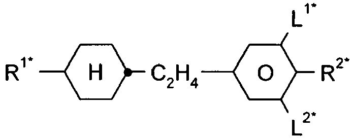
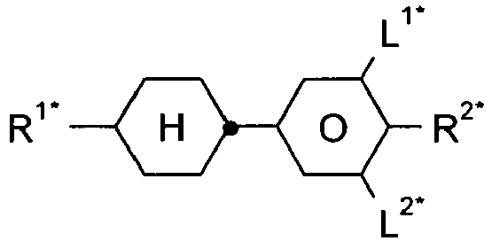
EPCH PCH 
CH 

PTP CCPC 

CP BECH 

EBCH CPC 

B FET-nF 
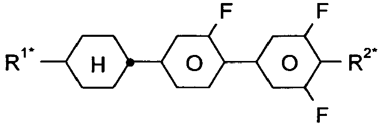
CGG CGU 
CFU Tabelle B (n = 1-15; (O)CnH2n+1 bedeutet CnH2n+1 oder OCnH2n+1) 
APU-n-OXF 
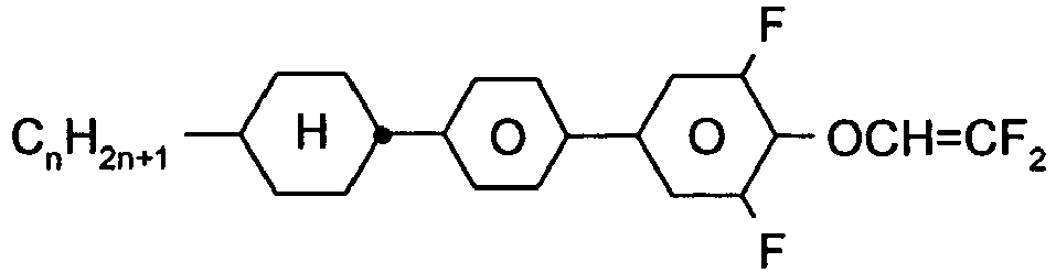
ACQU-n-F CPU-n-OXF 
APUQU-n-F 

BCH-n.Fm CFU-n-F 
CBC-nmF 
CCP-nOCF3 
CCP-nOCF3.F 

ECCP-nm CCZU-n-F 
ECCP-nOCF3 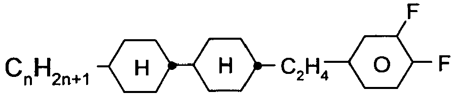
ECCP-nF.F 

PGP-n-m CGU-n-F 
CGUQU-n-F 
CLUQU-n-F 
CDUQU-n-F 

CDU-n-F DCU-n-F 

CGG-n-F CPZG-n-OT 
CC-nV-Vm 

CCP-Vn-m CCG-V-F 

CCP-nV-m CC-n-V 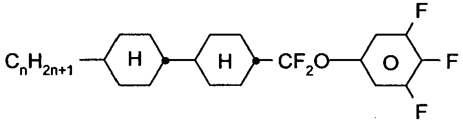

CCQU-n-F CC-n-Vm 
CPPC-nV-Vm 

CCQG-n-F CQU-n-F 
CP-1V-m 

CP-2V-m CP-V2-m 

CP-1V-N CP-V2-N 

CCP-nF CCP-nF.F 
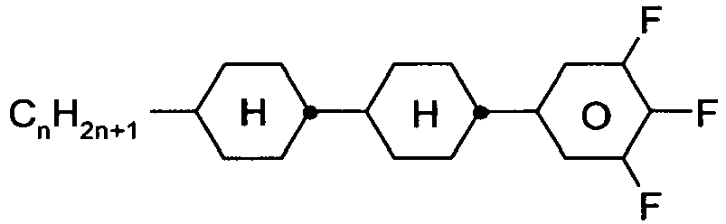
BCH-nF.F.F CCP-nF.F.F 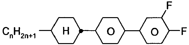
BCH-nF.F 

Dec-U-n-F CWCU-n-F 
CPGP-n-m 

CWCG-n-F GPP-n-m 
CCOC-n-m 

CPTU-n-F GPTU-n-F 

PQU-n-F PUQU-n-F 

PGU-n-F CGZP-n-OT 
PGU-n-OXF 
CCGU-n-F 
CUQU-n-F 
CCCQU-n-F 
CPGU-n-OT 
CPGU-n-F 

CVCP-1V-OT GGP-n-Cl 

PP-nV-Vm PP-1-nVm 
CWCQU-n-F 
PPGU-n-F 
PGUQU-n-F 

GPQU-n-F MPP-n-F 
PGP-n-kVm 
PP-n-kVm 

PCH-nCl GP-n-Cl 

PCH-nF PCH-n 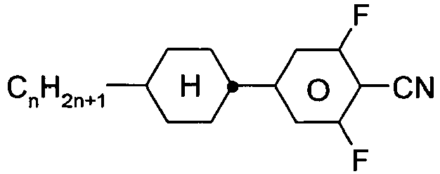
PCH-nN.F.F 

GGP-n-F PGIGI-n-F 
AIK-n-F 

BCH-nm BCH-nF / CPP-n-F 

BCN-nm CY-n-Om / PCH-nOmFF 
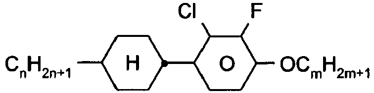
CP(F,Cl)-n-Om CP(Cl,F)-n-Om 

CCY-n-Om CCY-n-m 

CAIY-n-Om CAIY-n-m 

CCP(Cl,F)-n-Om CCP(F,Cl)-n-Om 

CCY-V-m CCY-Vn-m 

CCY-V-Om CCY-Vn-Om 
CCY-n-OmV 
CBC-nm 

CCP-V-m CCP-Vn-m 
CCP-n-m / CCP-nm 
CPYC-n-m 
CYYC-n-m 
CCYY-n-(O)m 
CCY-n-O2V 
CY-n-m 

CCH-nm / CC-n-m CCH-nOm / CC-n-Om 

CEY-n-Om CC-n-V1 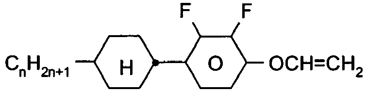

CY-n-OV CC-2V-V2 

CVC-n-m CC-n-mV 
CC-n-mV1 
CP-nOmFF 
CH-nm 

CEY-V-n CVY-V-n 

CY-V-On CY-n-OC(CH3)=CH2 

CY-n-O1V CCN-nm 
CY-1V-O1V 
CCPC-nm 
CCY-n-zOm 
CPY-n-m 
CPY-n-Om 

CPY-V-Om CPP(Cl,F)-n-(O)m 
CPY-1V-Om 

CQY-n-(O)m CPP(F,Cl)-n-(O)m 
CQIY-n-(O)m 
CCQY-n-(O)m 
CCQIY-n-(O)m 
CPQY-n-(O)m 
CPQIY-n-(O)m 
CPYG-n-(O)m 

CCY-V-Om D-nOmFF 
MEnN.F 

CY-nV-Om PCH-nm / CP-n-m 
CY-zVn-Om 
PY-zVn-Om 

PY-V-Om PY-1V-Om 
PCH-nOm / CP-n-Om 
DPGU-n-F 
DPGU-n-OT 
PP-n-m 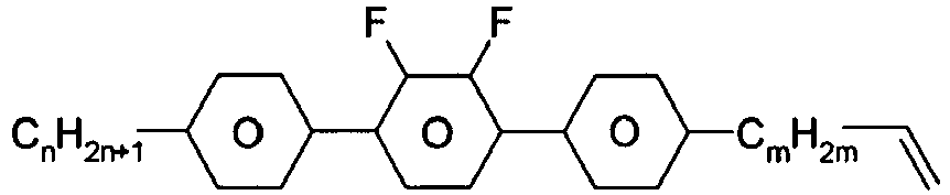

PYP-n-mV CYLI-n-m 

CENap-n-Om LY-n-(O)m 
CCNap-n-Om 

CNap-n-Om YPY-n-mV 
CETNap-n-Om 

CTNap-n-Om CK-n-F 

YPY-n-m LYLI-n-m 
C-DFDBF-n-(O)m 
B-nO-Om 
CPYG-n-(O)m 
DFDBC-n(O)-(O)m 
CCY-V2-(O)m 
CCY-1V2-(O)m 
CCY-3V-(O)m 
PYP-nF 

MUQU-n-F NUQU-n-F 
COChrom-n-Om 
COChrom-n-m 
CCOChrom-n-Om 
CCOChrom-n-m 
CONaph-n-Om 
CCONaph-n-Om 
CLY-n-Om 
CLY-n-m 
LYLI-n-m 
CYLI-n-m 
LY-n-(O)m 
COYOICC-n-m 
COYOIC-n-V 
CCOY-V-O2V 
CCOY-V-O3V 
COY-n-Om 
CCOY-n-Om 
PGIY-n-Om 
PYP-n-m 
PYP-n-Om 
YPY-n-m 
YPY-n-mV 
Y-nO-Om 
Y-n-Om 
PY-n-m 
PY-n-Om 
PY-V2-Om 
C-DFDBF-n-(O)m 
DFDBC-n(O)-(O)m 
DFDBC-n(O)-(O)m 

CPU-n-VT CPU-n-AT 
DGUQU-n-F 

C-n-V C-n-XF 
C-n-m 
CC-n-2V1 
CCVC-n-V 
DPGU-n-OT 

PTP-nOm PTP-nm 
CPTP-nOm 
PTP-nOmFF 
CPTP-nOmFF 
CPTP-n-m 
PPTUI-n-m - Besonders bevorzugt sind flüssigkristalline Mischungen, die neben einer oder mehreren Verbindungen der Formel I mindestens ein, zwei, drei, vier oder mehr Verbindungen aus der Tabelle B enthalten.
Tabelle C In der Tabelle C werden mögliche Dotierstoffe angegeben, die in der Regel den flüssigkristallinen Mischungen zugesetzt werden. Vorzugsweise enthalten die Mischungen 0-10 Gew.%, insbesondere 0,01-5 Gew.% und besonders bevorzugt 0,01-3 Gew.% an Dotierstoffen. 

C 15 CB 15 

CM 21 R/S-811 

CM 44 CM 45 

CM 47 CN 

R/S-2011 R/S-3011 

R/S-4011 R/S-5011 
R/S-1011 Tabelle D Stabilisatoren, die beispielsweise den flüssigkristallinen Mischungen in Mengen von 0-10 Gew.% zugesetzt werden können, werden nachfolgend genannt. (n = 1-12) 


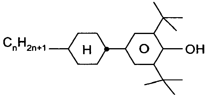
n= 1, 2, 3, 4, 5, 6 or 7 
n = 1, 2, 3, 4, 5, 6 or 7 

n = 1, 2, 3, 4, 5, 6 oder 7 


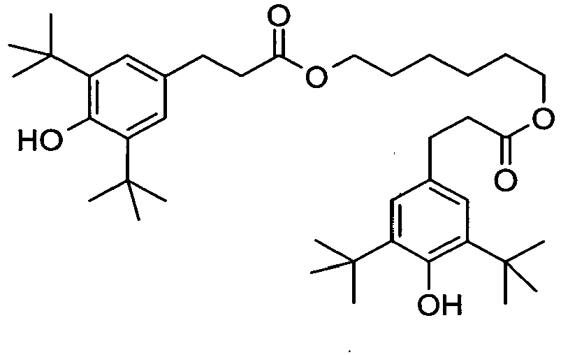


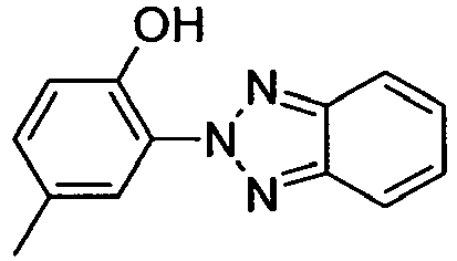


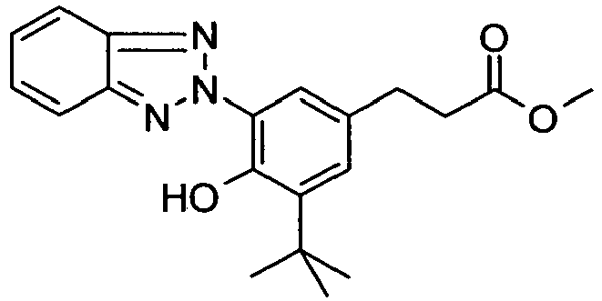


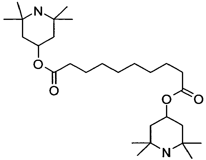


- Geeignete polymerisierbare Verbindungen (reaktive Mesogene) für den Einsatz in den erfindungsgemäßen Mischungen, vorzugsweise in PSA- und PS-VA-Anwendungen oder PS-IPS/FFS-Anwendungen, werden nachfolgend in Tabelle E genannt:
Tabelle E In der Tabelle E sind Beispielverbindungen zusammengestellt, die in den flüssigkristallinen Mischungen vorzugsweise als reaktive mesogene Verbindungen verwendet werden können. Sofern die flüssigkristallinen Mischungen ein oder mehrere reaktive Verbindungen enthalten, werden sie vorzugsweise in Mengen von 0,01-5 Gew.% eingesetzt. Gegebenenfalls muss für die Polymerisation noch ein Initiator oder ein Gemisch aus zwei oder mehr Initiatoren zugesetzt werden. Der Initiator oder das Initiatorgemisch wird vorzugsweise in Mengen von 0,001-2 Gew.% bezogen auf die Mischung zugesetzt. Ein geeigneter Initiator ist z. B. Irgacure (Fa. BASF) oder Irganox (Fa. BASF). 
RM-1 
RM-2 
RM-3 
RM-4 
RM-5 
RM-6 
RM-7 
RM-8 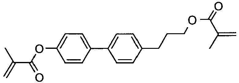
RM-9 
RM-10 
RM-11 
RM-12 
RM-13 
RM-14 
RM-15 
RM-16 
RM-17 
RM-18 
RM-19 
RM-20 
RM-21 
RM-22 
RM-23 
RM-24 
RM-25 
RM-26 
RM-27 
RM-28 
RM-29 
RM-30 
RM-31 
RM-32 
RM-33 
RM-34 
RM-35 
RM-36 
RM-37 
RM-38 
RM-39 
RM-40 
RM-41 
RM-42 
RM-43 
RM-44 
RM-45 
RM-46 
RM-47 
RM-48 
RM-49 
RM-50 
RM-51 
RM-52 
RM-53 
RM-54 
RM-55 
RM-56 
RM-57 
RM-58 
RM-59 
RM-60 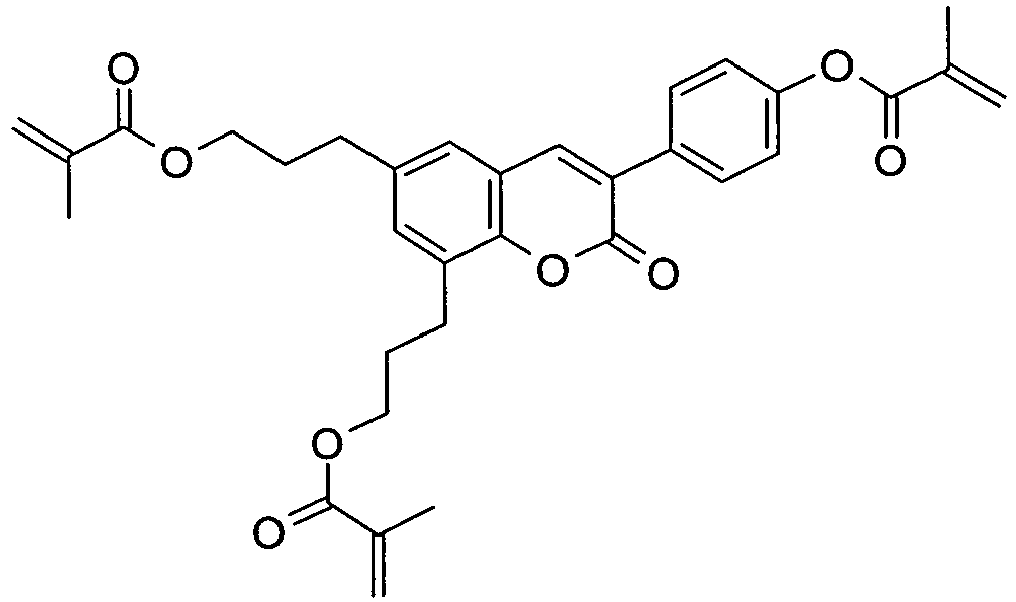
RM-61 
RM-62 
RM-63 
RM-64 
RM-65 
RM-66 
RM-67 
RM-68 
RM-69 
RM-70 
RM-71 
RM-72 
RM-73 
RM-74 
RM-75 
RM-76 
RM-77 
RM-78 
RM-79 
RM-80 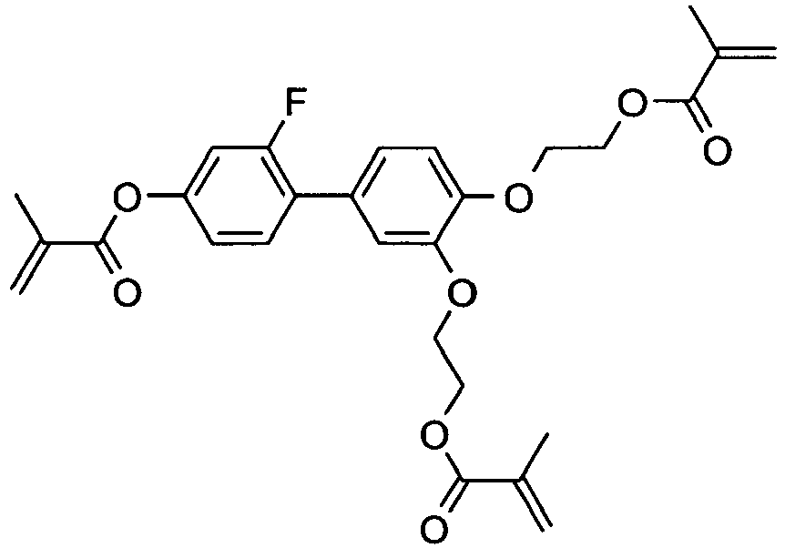
RM-81 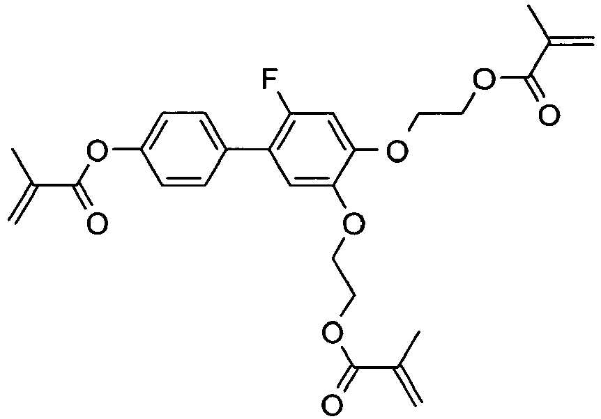
RM-82 
RM-83 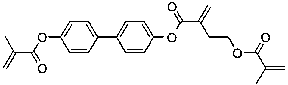
RM-84 
RM-85 
RM-86 
RM-87 
RM-88 
RM-89 
RM-90 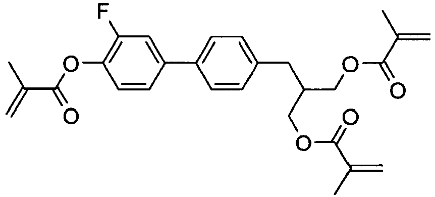
RM-91 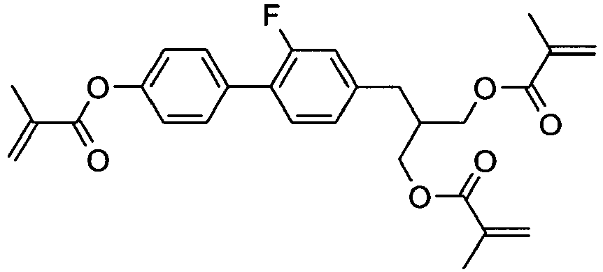
RM-92 
RM-93 
RM-94 
RM-95 - In einer bevorzugten Ausführungsform enthalten die flüssigkristallinen Mischungen eine oder mehrere Verbindungen ausgewählt aus der Gruppe der Verbindungen der Tabelle E.
- Die folgenden Ausführungsbeispiele sollen die Erfindung erläutern, ohne sie zu begrenzen.
- Vor- und nachstehend bedeuten Prozentangaben Gewichtsprozent. Alle Temperaturen sind in Grad Celsius angegeben. Fp. bedeutet Schmelzpunkt, cp. = Klärpunkt. Ferner bedeuten K = kristalliner Zustand, N = nematische Phase, S = smektische Phase und I = isotrope Phase. Die Angaben zwischen diesen Symbolen stellen die Übergangstemperaturen dar. Weiterhin bedeutet
- Vo
- Schwellenspannung, kapazitiv [V] bei 20 °C
- Δn
- die optische Anisotropie gemessen bei 20°C und 589nm
- Δε
- die dielektrische Anisotropie bei 20 °C und 1 kHz
- cp.
- Klärpunkt [°C]
- K1
- elastische Konstante, "Splay"-Deformation bei 20°C, [pN]
- K3
- elastische Konstante, "Bend"-Deformation bei 20°C, [pN]
- γ1
- Rotationsviskosität gemessen bei 20°C [mPa·s], bestimmt nach dem Rotationsverfahren in einem magnetischen Feld
- LTS
- Tieftemperaturstabilität [Low temperature stability (nematische Phase)], bestimmt in Testzellen.
- Die folgenden Beispiele sollen die Erfindung erläutern, ohne sie zu begrenzen.
- Vor- und nachstehend bedeuten Prozentangaben Gewichtsprozent. Alle Temperaturen sind in Grad Celsius angegeben.
- Eine flüssigkristalline Mischung, vorzugsweise für PS-VA-Anwendungen, der Zusammensetzung
CCH-35 9,47 % CCH-501 4,99 % CCY-2-1 9,47 % CCY-3-1 10,47 % CCY-3-O2 10,47 % CCY-5-O2 9,47 % CPY-2-O2 11,96 % CY-3-O4 8,97 % CY-5-O4 10,97 % RM-1 0,30 % PCH-53 13,46 % Fig. 1 undFig. 2 beschriebenen Abfüllvorrichtung in einen Behälter abgefüllt. - Eine flüssigkristalline Mischung, vorzugsweise für PS-VA-Anwendungen, der Zusammensetzung
BCH-32 7,48 % CCH-23 21,93 % CCH-34 3,49 % CCY-3-O3 6,98 % CCY-4-O2 7,98 % CPY-2-O2 10,97 % CPY-3-O2 10,97 % CY-3-O2 15,45 % RM-1 0,30 % PCH-301 12,46 % PCH-302 1,99 % Fig. 1 undFig. 2 beschriebenen Abfüllvorrichtung in einen Behälter abgefüllt. - Eine flüssigkristalline Mischung, vorzugsweise für PS-VA-Anwendungen, der Zusammensetzung
CC-3-V1 7,98 % CCH-23 17,95 % CCH-34 3,99 % CCH-35 6,98 % CCP-3-1 4,99 % CCY-3-02 12,46 % CPY-2-O2 7,98 % CPY-3-O2 10,97 % CY-3-O2 15,45 % RM-1 0,30 % PY-3-O2 10,97 % Fig. 1 undFig. 2 beschriebenen Abfüllvorrichtung in einen Behälter abgefüllt. - Eine flüssigkristalline Mischung, vorzugsweise für PS-VA-Anwendungen, der Zusammensetzung
CC-3-V1 8,97 % CCH-23 12,96 % CCH-34 6,23 % CCH-35 7,73 % CCP-3-1 3,49 % CCY-3-O2 12,21 % CPY-2-O2 6,73 % CPY-3-O2 11,96 % CY-3-O2 11,47 % RM-1 0,30 % PP-1-2V1 4,24 % PY-3-02 13,71 % Fig. 1 undFig. 2 beschriebenen Abfüllvorrichtung in einen Behälter abgefüllt. - Eine flüssigkristalline Mischung, vorzugsweise für TN-TFT-Anwendungen, der Zusammensetzung
CBC-33 3,50 % CC-3-V 38,00 % CC-3-V1 10,00 % CCP-V-1 3,00 % CCP-V2-1 9,00 % PGP-2-3 5,00 % PGP-2-4 5,00 % PGU-2-F 8,00 % PGU-3-F 9,00 % PUQU-3-F 9,50 % Fig. 1 undFig. 2 beschriebenen Abfüllvorrichtung in einen Behälter abgefüllt. - Eine flüssigkristalline Mischung, vorzugsweise für IPS- oder FFS-Anwendungen, der Zusammensetzung
APUQU-3-F 4,50 % CC-3-V 44,00 % CC-3-V1 12,00 % CCP-V-1 11,00 % CCP-V2-1 9,00 % PGP-2-3 6,00 % PGUQU-3-F 6,00 % PP-1-2V1 7,00 % PPGU-3-F 0,50 % Fig. 1 undFig. 2 beschriebenen Abfüllvorrichtung in einen Behälter abgefüllt. - Eine flüssigkristalline Mischung, vorzugsweise für IPS- oder FFS-Anwendungen, der Zusammensetzung
APUQU-3-F 8,00 % CBC-33 3,00 % CC-3-V 34,00 % CC-3-V1 2,50 % CCGU-3-F 4,00 % CCP-30CF3 4,00 % CCP-3F.F.F 4,50 % CCP-50CF3 3,00 % CCP-V-1 10,00 % CCQU-3-F 10,00 % CPGU-3-OT 6,00 % PGUQU-3-F 4,00 % PUQU-3-F 7,00 % Fig. 1 undFig. 2 beschriebenen Abfüllvorrichtung in einen Behälter abgefüllt. - Eine flüssigkristalline Mischung, vorzugsweise für IPS- oder FFS-Anwendungen, der Zusammensetzung
APUQU-2-F 5,00 % APUQU-3-F 7,50 % BCH-3F.F.F 7,00 % CC-3-V 40,50 % CC-3-V1 6,00 % CCP-V-1 9,50 % CPGU-3-OT 5,00 % PGP-2-3 6,00 % PGP-2-4 6,00 % PPGU-3-F 0,50 % PUQU-3-F 7,00 % Fig. 1 undFig. 2 beschriebenen Abfüllvorrichtung in einen Behälter abgefüllt. - Eine flüssigkristalline Mischung, vorzugsweise für TN-TFT-Anwendungen, der Zusammensetzung
APUQU-2-F 8,00 % APUQU-3-F 8,00 % BCH-32 7,00 % CC-3-V 43,00 % CCP-V-1 9,00 % PGP-2-3 7,00 % PGP-2-4 6,00 % PUQU-2-F 5,00 % PUQU-3-F 7,00 % Fig. 1 undFig. 2 beschriebenen Abfüllvorrichtung in einen Behälter abgefüllt. - Eine flüssigkristalline Mischung, vorzugsweise für TN-TFT-Anwendungen, der Zusammensetzung
BCH-5F.F 8,00 % CBC-33F 3,00 % CC-3-V 22,00 % CCGU-3-F 6,00 % CCP-3F.F.F 8,00 % CCP-5F.F.F 4,00 % CCP-V-1 13,00 % CCP-V2-1 11,00 % CCQU-3-F 5,00 % CCQU-5-F 4,00 % PUQU-3-F 16,00 % Fig. 1 undFig. 2 beschriebenen Abfüllvorrichtung in einen Behälter abgefüllt. - Eine flüssigkristalline Mischung, vorzugsweise für TN-TFT-Anwendungen, der Zusammensetzung
CBC-33F 3,00 % CBC-53F 3,00 % CC-3-V 17,00 % CC-3-V1 4,00 % CCP-3F.F.F 8,00 % CCPC-33 3,00 % CCPC-34 3,00 % CCP-V-1 5,00 % CCP-V2-1 2,00 % CCQU-2-F 1,50 % CCQU-3-F 10,00 % CCQU-5-F 10,00 % CGU-3-F 6,00 % PGP-2-3 7,50 % PP-1-2V1 7,00 % PUQU-3-F 10,00 % Fig. 1 undFig. 2 beschriebenen Abfüllvorrichtung in einen Behälter abgefüllt. - Eine flüssigkristalline Mischung, vorzugsweise für TN-TFT-Anwendungen, der Zusammensetzung
APUQU-2-F 1,00 % BCH-3F.F.F 15,00 % CC-3-V 33,50 % CC-3-V1 2,00 % CCGU-3-F 1,00 % CCPC-33 2,00 % CCP-V-1 4,50 % BCH-2F 5,00 % BCH-3F 5,00 % PGP-2-3 8,50 % PGUQU-3-F 7,80 % PP-1-2V1 11,00 % PPGU-3-F 0,20 % PUQU-3-F 3,50 % Fig. 1 undFig. 2 beschriebenen Abfüllvorrichtung in einen Behälter abgefüllt. - Eine flüssigkristalline Mischung, vorzugsweise für IPS- oder FFS-Anwendungen, der Zusammensetzung
APUQU-2-F 2,00 % APUQU-3-F 6,00 % CC-3-V 42,00 % CCP-3-1 3,00 % CCP-3-3 3,00 % CCP-3F.F.F 8,00 % CCP-V-1 1,50 % CCQU-3-F 7,00 % CCQU-5-F 3,00 % CPGU-3-OT 6,50 % PGUQU-3-F 5,00 % PGUQU-4-F 4,00 % PGUQU-5-F 4,00 % PPGU-3-F 0,50 % PUQU-3-F 4,50 % Fig. 1 undFig. 2 beschriebenen Abfüllvorrichtung in einen Behälter abgefüllt. - Eine flüssigkristalline Mischung, vorzugsweise für TN-TFT -Anwendungen, der Zusammensetzung
CC-3-V 49,50 % CCP-3-1 1,50 % CCP-V-1 6,00 % CPGU-3-OT 7,00 % PGP-2-3 8,50 % PGP-2-4 5,50 % PGUQU-3-F 7,00 % PGUQU-4-F 4,00 % PP-1-2V1 2,50 % PPGU-3-F 0,50 % PUQU-3-F 8,00 % Fig. 1 undFig. 2 beschriebenen Abfüllvorrichtung in einen Behälter abgefüllt. - Eine flüssigkristalline Mischung, vorzugsweise für VA-Anwendungen, der Zusammensetzung
BCH-32 6,00 % CCH-23 18,00 % CCH-34 8,00 % CCP-3-1 12,00 % CCP-3-3 3,00 % CCY-3-02 6,00 % CPY-2-O2 6,00 % CPY-3-O2 7,00 % CY-3-02 14,00 % CY-3-O4 8,00 % CY-5-O2 9,00 % PYP-2-3 3,00 % Fig. 1 undFig. 2 beschriebenen Abfüllvorrichtung in einen Behälter abgefüllt. - Eine flüssigkristalline Mischung, vorzugsweise für PS-VA-Anwendungen, der Zusammensetzung
CC-3-V1 7,98 % CCH-23 17,95 % CCH-34 3,99 % CCH-35 6,98 % CCP-3-1 4,99 % CCY-3-O2 12,46 % CPY-2-O2 7,98 % CPY-3-O2 10,97 % CY-3-O2 15,45 % RM-17 0,30 % PY-3-O2 10,97 % Fig. 1 undFig. 2 beschriebenen Abfüllvorrichtung in einen Behälter abgefüllt. - Eine flüssigkristalline Mischung, vorzugsweise für VA-Anwendungen, der Zusammensetzung
CC-3-V 29,50 % PP-1-3 11,00 % PY-3-O2 12,00 % CCP-3-1 9,50 % CCOY-2-O2 18,00 % CCOY-3-O2 13,00 % GPP-5-2 7,00 % Fig. 1 undFig. 2 beschriebenen Abfüllvorrichtung in einen Behälter abgefüllt. - Die Mischungsbeispiele 1 bis 17 können zusätzlich noch einen oder mehrere, vorzugsweise einen oder zwei, Stabilisator(en), und/oder einen Dotierstoff aus den Tabellen C und D enthalten.
- Die nachfolgend genannten Flüssigkristallmischungenen gemäß der Beispiele 18 - 168 werden analog gemäß der in
Fig. 1 undFig. 2 beschriebenen Abfüllvorrichtung in einen Behälter abgefüllt. -
CCY-3-O1 7,50 % CCY-4-O2 3,50 % CLY-3-O2 7,00 % CPY-2-O2 10,00 % CPY-3-O2 10,00 % PYP-2-3 9,00 % CC-3-V 45,00 % PY-1-O4 4,00 % PY-3-O2 2,00 % Y-4O-O4 2,00 % Klärpunkt f°C1: 81,5 Δn [589 nm, 20°C]: 0,1082 Δε [1 kHz, 20°C]: -2,7 ε∥ [1 kHz, 20°C]: 3,4 ε⊥ [1 kHz, 20°C]: 6,1 γ1 [mPa·s, 20°C]: 88 K1 [pN, 20°C]: 13,4 K3 [pN, 20°C]: 15,3 V0 [20°C, V]: 2,53 -


-
CC-3-2V1 4,00 % CC-3-V 37,50 % CC-3-V1 5,00 % CCP-V-1 13,00 % CCP-V2-1 7,50 % CCVC-3-V 6,00 % CDUQU-3-F 1,00 % CPGP-5-2 3,00 % DGUQU-4-F 2,00 % PGP-2-3 5,00 % PGP-2-4 3,00 % PGUQU-3-F 4,00 % PGUQU-4-F 3,50 % PPGU-3F 0,50 % PUQU-3F 5,00 % Klärpunkt [°C]: 100 Δn [589 nm, 20°C]: 0,1047 Δε [1 kHz, 20°C]: 3,9 ε∥ [1 kHz, 20°C]: 6,6 ε⊥ [1 kHz, 20°C]: 2,7 γ1 [mPa·s, 20°C]: 72 K1 [pN, 20°C]: 15,1 K3 [pN, 20°C]: 17,4 V0 [20°C, V]: 2,07 -


-
CC-3-V1 9,00 % CCH-23 18,00 % CCH-34 3,00 % CCH-35 7,00 % CCP-3-1 5,50 % CCY-3-O2 11,50 % CPY-2-O2 8,00 % CPY-3-O2 11,00 % CY-3-O2 15,50 % PY-3-O2 11,50 % Klärpunkt [°C]: 74,7 Δn [589 nm, 20°C]: 0,0982 Δε [1 kHz, 20°C]: -3,4 ε∥ [1 kHz, 20°C]: 3,5 ε⊥ [1 kHz, 20°C]: 6,9 γ1 [mPa·s, 20°C]: 108 K1 [pN, 20°C]: 14,9 K3 [pN, 20°C]: 15,9 V0 [20°C, V]: 2,28 - Die Mischung aus Beispiel 22 wird zusätzlich mit 0,001 % Irganox® 1076 (Octadecyl-3-(3,5-di-tert. butyl-4-hydroxyphenyl)-proprionat, Fa. BASF) und 0,45 % RM-1 versetzt.
-


-
CC-3-V 28,00 % CC-3-V1 3,00 % CCP-3-1 3,00 % CCY-3-O2 9,00 % CCY-4-O2 9,00 % CLY-3-O2 6,00 % CLY-3-O3 6,00 % CPY-2-O2 7,00 % CPY-3-O2 9,00 % PY-3-O2 8,00 % PY-4-O2 4,00 % PYP-2-4 2,50 % Y-4O-O4 5,50 % Klärpunkt [°C]: 84,8 Δn [589 nm, 20°C]: 0,1078 Δε [1 kHz, 20°C]: -4,1 ε∥ [1 kHz, 20°C] 3,7 ε⊥ [1 kHz, 20°C 7,8 γ1 [mPa·s, 20°C]: 122 K1 [pN, 20°C]: 14,8 - Die Mischung aus Beispiel 24 wird zusätzlich mit
0,04 % 
0,01 % 
-
CC-3-V 28,00 % CC-3-V1 5,00 % CCP-3-1 2,50 % CCY-3-O2 10,00 % CCY-4-O2 2,50 % CLY-3-O2 6,50 % CLY-3-O3 6,50 % CPY-2-O2 9,00 % CPY-3-O2 10,00 % PY-3-O2 10,00 % PY-4-O2 5,00 % Y-4O-O4 5,00 % Klärpunkt [C°]: 80 Δn [589 nm, 20°C]: 0,1082 Δε [1 kHz, 20°C]: -4,1 ε∥ [1 kHz, 20°C]: 3,8 ε⊥ [1 kHz, 20°C]: 7,9 γ1 [mPa·s, 20°C]: 113 K1 [pN, 20°C]: 14,5 - Die Mischung aus Beispiel 25 wird zusätzlich mit
0,04 % 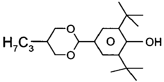
0,01 % 
-
CC-3-V 29,00 % CC-3-V1 5,00 % CCP-3-1 3,00 % CCY-3-O2 10,00 % CLY-3-O2 6,00 % CLY-3-O3 6,00 % CPY-2-O2 9,00 % CPY-3-O2 10,00 % PY-3-O2 10,00 % PY-4-02 7,00 % Y-4O-O4 5,00 % Klärpunkt [°C]: 75,1 Δn [589 nm, 20°C]: 0,1075 Δε [1 kHz, 20°C]: -4,0 ε∥ [1 kHz, 20°C]: 3,8 ε⊥ [1 kHz, 20°C]: 7,7 γ1 [mPa·s, 20°C 103 K1 [pN, 20°C]: 14,3 - Die Mischung aus Beispiel 26 wird zusätzlich mit
0,04 % 
0,015 % 
-
CC-3-V 29,00 % CCY-3-O1 8,00 % CCY-3-O2 6,00 % CCY-4-O2 2,00 % CLY-3-O2 8,50 % CLY-3-O3 7,50 % CPY-2-O2 10,00 % CPY-3-O2 7,50 % CY-3-02 6,50 % PY-3-O2 10,00 % Y-4O-O4 5,00 % Klärpunkt [°C]: 80,1 Δn [589 nm, 20°C]: 0,1052 Δε [1 kHz, 20°C]: -4,7 ε∥ [1 kHz, 20°C]: 3,9 ε⊥ [1 kHz, 20°C]: 8,7 γ1 [mPa·s, 20°C]: 125 K1 [pN, 20°C]: 14,0 - Die Mischung aus Beispiel 27 wird zusätzlich mit
0,04 % 
0,02 % 
-
CC-3-V 37,00 % CCY-3-O1 5,00 % CCY-3-O2 5,00 % CCY-4-O2 4,00 % CLY-3-O2 7,00 % CPY-2-O2 9,00 % CPY-3-O2 10,00 % CY-3-O2 12,00 % PY-3-O2 11,00 % Klärpunkt [°C]: 75,2 Δn [589 nm, 20°C]: 0,1012 Δε [1 kHz, 20°C]: -3,8 ε∥ [1 kHz, 20°C]: 3,6 ε⊥ [1 kHz, 20°C]: 7,5 γ1 [mPa·s, 20°C]: 97 K1 [pN, 20°C]: 13,3 K3 [pN, 20°C]: 15,3 V0 [20°C, V]: 2,12 - Die Mischung aus Beispiel 28 wird zusätzlich mit
0,04 % 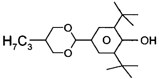
0,015 % 
-
CY-3-O2 15,00 % CY-5-O2 12,50 % CCY-3-O1 2,50 % CCY-4-O2 5,00 % CPY-2-O2 8,00 % CPY-3-O2 8,00 % CCY-2-1 6,00 % CCY-3-1 6,00 % CCH-23 15,00 % CCH-34 5,00 % CCH-301 1,50 % BCH-32 15,50 % Klärpunkt [°C]: 80,4 Δn [589 nm, 20°C]: 0,1038 Δε [1 kHz, 20°C]: -3,3 ε∥ [1 kHz, 20°C]: 3,5 ε⊥ [1 kHz, 20°C]: 6,8 γ1 [mPa·s, 20°C]: 137 K1 [pN, 20°C 14,2 K3 [pN, 20°C]: 14,2 V0 [20°C, V]: 2,18 - Die Mischung aus Beispiel 29 wird zusätzlich mit
0,01 % 
-
CY-3-O2 15,00 % CY-3-O4 20,00 % CY-5-O2 7,50 % CCY-3-O2 6,50 % CCY-3-O3 6,50 % CCY-4-O2 6,50 % CCY-5-O2 6,50 % CPY-2-O2 5,50 % CPY-3-O2 5,00 % CC-4-V 3,00 % CH-33 3,00 % CH-35 2,00 % CH-43 3,00 % CH-45 2,00 % CCPC-33 4,00 % CCPC-34 4,00 % Klärpunkt [°C]: 100 Δn [589 nm, 20°C]: 0,0968 Δε [1 kHz, 20°C]: -5,9 ε∥ [1 kHz, 20°C 4,0 ε⊥ [1 kHz, 20°C]: 9,9 γ1 [mPa·s, 20°C 324 K1 [pN, 20°C]: 15,1 K3 [pN, 20°C]: 17,2 V0 [20°C, V]: 1,80 -


-
CY-3-O2 8,00 % CY-3-O4 13,00 % CCY-3-O2 6,50 % CPY-2-O2 3,50 % CPY-3-O2 8,00 % CCH-301 5,00 % CC-4-V 12,00 % CC-5-V 8,00 % CCP-V-1 13,00 % CCP-V2-1 13,00 % BCH-32 5,00 % CCPC-33 5,00 % Klärpunkt [°C]: 101 Δn [589 nm, 20°C]: 0,0970 Δε [1 kHz, 20°C]: -2,1 ε∥ [1 kHz, 20°C]: 3,2 ε⊥ [1 kHz, 20°C 5,3 γ1 20°C]: 136 K1 [pN, 20°C]: 14,8 K3 [pN, 20°C]: 18,3 V0 [20°C, V]: 3,11 -


-
CY-3-O2 15,00 % CCH-3-O1 6,00 % CCY-3-O2 8,00 % CCY-3-O3 5,50 % CCY-4-O2 8,00 % CCY-5-O2 8,00 % CPY-2-O2 1,50 % CPY-3-O2 10,00 % CLY-3-O2 8,00 % PY-3-O2 6,00 % PY-1-O4 8,00 % PY-4-O2 8,00 % Y-4O-O4 8,00 % Klärpunkt [°C]: 71,9 Δn [589 nm, 20°C]: 0,1203 Δε [1 kHz, 20°C]: -8,1 ε∥ [1 kHz, 20°C]: 5,2 ε⊥ [1 kHz, 20°C]: 13,3 γ1 [mPa·s, 20°C]: 253 K1 [pN, 20°C]: 13,2 K3 [pN, 20°C]: 15,7 V0 [20°C, V]: 1,46 -
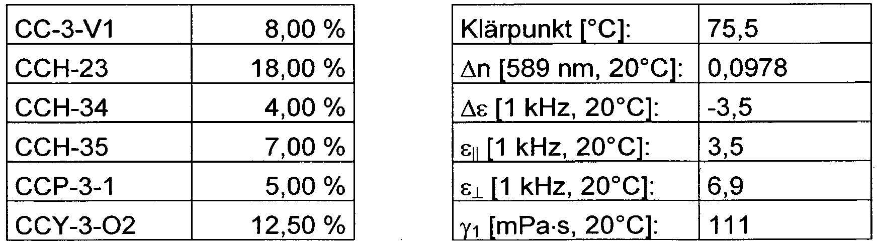

- Die Mischung aus Beispiel 35 wird zusätzlich mit 0,3 % RM-1

-
BCH-32 1,50 % CC-3-V 15,50 % CC-3-V1 11,00% CCH-23 12,00 % CCH-34 3,50 % CCY-3-O2 11,50 % CCY-5-O2 0,50 % CPY-2-O2 8,50 % CPY-3-O2 12,00 % CY-3-O2 9,50 % PY-3-O2 11,50 % PYP-2-3 3,00 % Klärpunkt [°C]: 74,8 Δn [589 nm, 20°C]: 0,1035 Δε [1 kHz, 20°C]: -3,1 ε∥ [1 kHz, 20°C]: 3,4 ε⊥ [1 kHz, 20°C]: 6,5 γ1 [mPa·s, 20°C]: 95 K1 [pN, 20°C]: 14,1 K3 [pN, 20°C]: 15,4 V0 [20°C, V]: 2,36 - Die Mischung aus Beispiel 36 wird zusätzlich mit 0,001 % Irganox® 1076 (Octadecyl-3-(3,5-di-tert. butyl-4-hydroxyphenyl)-proprionat, Fa. BASF) und 0,3 % RM-1 versetzt.
-
CC-3-V 30,50 % CC-3-V1 4,50 % CCH-3-O1 5,00 % CCY-3-O2 6,00 % CCY-3-O3 4,00 % CLY-3-O2 8,00 % CPY-2-O2 8,00 % CPY-3-O2 11,00 % CY-3-O2 15,00 % PY-3-O2 8,00 % Klärpunkt [°C]: 79,8 Δn [589 nm, 20°C]: 0,1022 Δε [1 kHz, 20°C]: -4,0 ε∥ [1 kHz, 20°C]: 3,6 ε⊥ [1 kHz, 20°C]: 7,6 γ1 [mPa·s, 20°C]: 114 K1 [pN, 20°C]: 14,5 K3 [pN, 20°C]: 16,7 V0 [20°C, V]: 2,14 -
CY-3-O2 15,00 % CY-5-O2 12,50 % CCH-3-O1 2,50 % CCY-4-O2 5,00 % CPY-2-O2 8,00 % CPY-3-O2 8,00 % CCY-2-1 6,00 % CCY-3-1 6,00 % CCH-23 15,00 % CCH-34 5,00 % CCH-301 1,50 % BCH-32 15,50 % Klärpunkt [°C]: 80,4 Δn [589 nm, 20°C]: 0,1038 Δε [1 kHz, 20°C]: -3,3 ε∥ [1 kHz, 20°C]: 3,5 ε⊥ [1 kHz, 20°C]: 6,8 γ1 [mPa·s, 20°C]: 137 K1 [pN, 20°C]: 14,2 K3 [pN, 20°C]: 14,2 V0 [20°C, V]: 2,18 -
CY-3-02 15,00 % CY-3-O4 4,00 % CY-5-O2 6,50 % CCY-3-O1 5,00 % CCY-3-O3 2,00 % CCY-4-O2 6,00 % CPY-2-O2 7,00 % CPY-3-O2 7,00 % CCY-2-1 6,00 % CCY-3-1 6,00 % CCH-23 15,50 % CCH-34 5,00 % BCH-32 13,00 % PP-1-4 2,00 % Klärpunkt [°C]: 80,5 Δn [589 nm, 20°C]: 0,1025 Δε [1 kHz, 20°C]: -3,4 ε∥ [1 kHz, 20°C]: 3,5 ε⊥ [1 kHz, 20°C]: 6,9 γ1 [mPa·s, 20°C]: 141 K1 [pN, 20°C]: 14,0 K3 [pN, 20°C]: 14,1 V0 [20°C, V]: 2,16 -
PGUQU-3-F 4,00 % CCQU-3-F 7,50 % PUQU-3-F 15,50 % APUQU-2-F 4,00 % APUQU-3-F 7,50 % CC-3-V 27,50 % CCP-3-V1 6,00 % CCP-V-1 13,00 % CCP-V2-1 10,00 % PPGU-3-F 0,50 % BCH-3F.F 4,50 % Klärpunkt [°C]: 85,4 Δn [589 nm, 20°C]: 0,1028 Δε [1 kHz, 20°C]: 9,9 ε∥ [1 kHz, 20°C]: 13,3 ε⊥ [1 kHz, 20°C]: 3,4 γ1 [mPa·s, 20°C]: 82 K1 [pN, 20°C]: 12,6 K3 [pN, 20°C]: 15,3 V0 [20°C, V]: 1,19 - Die Mischung aus Beispiel 40 wird zusätzlich mit
0,01 % 
-
CC-3-V 30,50 % CC-3-V1 4,50 % CCH-3-O1 6,00 % CCY-3-O2 8,00 % CLY-3-O2 8,00 % CPY-2-O2 8,00 % CPY-3-O2 12,00 % CY-3-O2 15,00 % PY-3-O2 8,00 % Klärpunkt [°C]: 80,1 Δn [589 nm, 20°C]: 0,1033 Δε [1 kHz, 20°C]: -4,0 ε∥ [1 kHz, 20°C]: 3,6 ε⊥ [1 kHz, 20°C]: 7,6 γ1 [mPa·s, 20°C]: 113 K1 [pN, 20°C]: 14,4 K3 [pN, 20°C]: 17,0 V0 [20°C, V]: 2,16 - Die Mischung aus Beispiel 41 wird zusätzlich mit
0,3 % 
-
CC-3-V 28,50 % CC-3-V1 7,00 % CCY-3-O2 12,50 % CCY-4-O2 5,25 % CPY-3-O2 9,75 % CY-3-O2 15,00 % CY-3-O4 4,75 % CY-5-O2 1,00 % PCH-301 3,25 % PPGU-3-F 0,50 % PYP-2-3 12,50 % Klärpunkt [°C]: 74,6 Δn [589 nm, 20°C]: 0,1040 Δε [1 kHz, 20°C]: -3,0 ε∥ [1 kHz, 20°C]: 3,5 ε⊥ [1 kHz, 20°C]: 6,5 γ1 [mPa·s, 20°C]: 98 K1 [pN, 20°C]: 13,2 K3 [pN, 20°C]: 15,5 V0 [20°C, V]: 2,4 - Die Mischung aus Beispiel 42 wird zusätzlich mit 0,001 % Irganox® 1076 (Octadecyl-3-(3,5-di-tert. butyl-4-hydroxyphenyl)-proprionat, Fa. BASF) und 0,45 % RM-1 versetzt.
-


-
BCH-32 4,50 % CCH-23 14,00 % CCH-301 7,00 % CCH-34 9,00 % CCH-35 5,50 % CCP-3-1 10,00 % CY-3-O2 5,00 % CY-V-02 7,00 % CCY-3-O1 5,00 % CCY-3-O2 9,00 % CPY-V-O2 10,00 % PCH-302 5,00 % PY-V2-O2 9,00 % Klärpunkt [°C]: 75,5 Δn [589 nm, 20°C]: 0,0938 Δε [1 kHz, 20°C]: -2,5 ε∥ [1 kHz, 20°C]: 3,3 ε⊥ [1 kHz, 20°C]: 5,8 γ1 [mPa·s, 20°C]: 89 K1 [pN, 20°C]: 13,5 K3 [pN, 20°C]: 14,5 V0 [20°C, V]: 2,54 -
BCH-32 1,50 % CC-3-V 37,00 % CCP-3-1 8,00 % CY-3-O2 15,00 % CCH-3-O1 7,00 % CCY-3-O2 9,50 % CPY-3-O2 8,50 % PCH-302 5,50 % PY-V-O2 8,00 % Klärpunkt [°C]: 75 Δn [589 nm, 20°C]: 0,0960 Δε [1 kHz, 20°C]: -2,6 ε∥ [1 kHz, 20°C]: 3,4 ε⊥ [1 kHz, 20°C]: 6,0 γ1 [mPa·s, 20°C]: 79 K1 [pN, 20°C]: 13,0 K3 [pN, 20°C] 16,0 V0 [20°C, V]: 2,6 -
BCH-32 1,00 % CC-3-V 41,00 % CCP-3-1 8,50 % CY-3-O2 13,00 % CCY-3-O1 6,50 % CCY-3-O2 8,50 % CPY-3-O2 6,00 % PCH-302 7,00 % PY-1V-O2 8,50 % Klärpunkt [°C]: 75 Δn [589 nm, 20°C]: 0,0948 Δε [1 kHz, 20°C]: -2,3 ε∥ [1 kHz, 20°C]: 3,2 ε⊥ [1 kHz, 20°C]: 5,5 γ1 [mPa·s, 20°C]: 70 K1 [pN, 20°C]: 13,4 K3 [pN, 20°C]: 16,5 V0 [20°C, V]: 2,84 -
PY-3-O2 7,50 % PY-1V-O2 4,00 % CY-3-O2 14,50 % CCH-3-O1 3,00 % CCY-3-O2 9,00 % CPY-2-O2 7,50 % CPY-3-O2 9,00 % CC-3-V 37,00 % BCH-32 8,00 % PPGU-3-F 0,50 % Klärpunkt [°C]: 74 An [589 nm, 20°C]: 0,1094 Δε [1 kHz, 20°C]: -3,0 ε∥ [1 kHz, 20°C]: 3,6 ε⊥ [1 kHz, 20°C]: 6,6 γ1 [mPa·s, 20°C]: 85 K1 [pN, 20°C]: 12,9 K3 [pN, 20°C]: 14,6 V0 [20°C, V]: 2,34 -


-
PY-V2-O2 12,00 % CY-V-O2 9,00 % CCH-3-O1 9,00 % CCY-V2-O2 8,00 % CPY-2-O2 8,00 % CPY-V-O2 10,50 % CC-3-V 36,50 % BCH-32 6,50 % PPGU-3-F 0,50 % Klärpunkt [°C]: 76 Δn [589 nm, 20°C]: 0,1087 Δε [1 kHz, 20°C]: -3,1 ε∥ [1 kHz, 20°C]: 3,7 ε⊥ [1 kHz, 20°C]: 6,9 γ1 [mPa·s, 20°C]: 83 K1 [pN, 20°C]: 12,4 K3 [pN, 20°C]: 14,7 V0 [20°C, V]: 2,28 -
PY-V2-O2 11,50 % CY-3-O2 11,00 % CCY-3-O1 9,00 % CCY-3-O2 4,00 % CPY-2-O2 12,00 % CPY-3-O2 9,00 % CC-3-V 37,00 % BCH-32 6,00 % PPGU-3-F 0,50 % Klärpunkt [°C]: 75,5 Δn [589 nm, 20°C]= 0,1074 Δε [1 kHz, 20°C]: -3,1 ε∥ [1 kHz, 20°C]: 3,7 ε⊥ [1 kHz, 20°C]: 6,8 γ1 [mPa·s, 20°C]: 87 K1 [pN, 20°C]: 13,0 K3 [pN, 20°C]: 14,7 V0 [20°C, V]: 2,29 -
PY-1V-O2 10,50 % CY-3-O2 18,00 % CCH-3-O1 7,00 % CCY-3-O2 5,00 % CPY-2-O2 7,00 % CPY-3-O2 8,00 % CC-3-V 41,00 % BCH-32 3,00 % PPGU-3-F 0,50 % Klärpunkt [°C]: 72 Δn [589 nm, 20°C]: 0,1068 Δε [1 kHz, 20°C]: -3,1 ε∥ [1 kHz, 20°C]: 3,6 ε⊥ [1 kHz, 20°C]: 6,7 γ1 [mPa·s, 20°C]: 78 K1 [pN, 20°C]: 12,6 K3 [pN, 20°C 14,6 V0 [20°C, V]: 2,30 -
PY-V2-O2 10,50 % CY-3-O2 10,00 % CCH-3-O1 6,00 % CCY-3-O2 9,00 % CPY-2-O2 8,00 % CPY-3-O2 12,00 % CC-3-V 35,00 % BCH-32 6,50 % PPGU-3-F 0,50 % Y-4O-O4 2,50 % Klärpunkt [°C]: 75 Δn [589 nm, 20°C]: 0,1070 Δε [1 kHz, 20°C]: -3,3 ε∥ [1 kHz, 20°C]: 3,7 ε⊥ [1 kHz, 20°C]: 7,0 γ1 [mPa·s, 20°C]: 90 K1 [pN, 20°C]: 12,7 K3 [pN, 20°C] 14,5 V0 [20°C, V]: 2,23 LTS (bulk) [-20°C]: > 1000 h LTS (bulk) [-30°C]: > 1000 h -


-
PY-V2-O2 11,50 % CY-3-O2 10,00 % CCH-3-O1 4,50 % CCY-3-O2 11,00 % CPY-2-O2 7,00 % CPY-3-O2 12,50 % CC-3-V 34,50 % BCH-32 6,00 % PPGU-3-F 0,50 % Y-4O-O4 2,50 % Klärpunkt [°C]: 74,5 Δn [589 nm, 20°C]: 0,1071 Δε [1 kHz, 20°C]: -3,4 ε∥ [1 kHz, 20°C]: 3,8 ε⊥ [1 kHz, 20°C]: 7,1 γ1 [mPa·s, 20°C]: 91 K1 [pN, 20°C]: 12,7 K3 [pN, 20°C]: 14,6 V0 [20°C, V]: 2,2 -
PY-V2-O2 14,00 % CY-3-O2 10,50 % CCH-3-O1 5,00 % CCY-3-O2 10,00 % CPY-2-O2 9,00 % CPY-3-O2 12,00 % CC-3-V 36,50 % BCH-32 2,50 % PPGU-3-F 0,50 % Klärpunkt [°C]: 74,5 Δn [589 nm, 20°C]: 0,1075 Δε [1 kHz, 20°C]: -3,2 ε∥ [1 kHz, 20°C]: 3,6 ε⊥ [1 kHz, 20°C 6,8 γ1 [mPa·s, 20°C]: 90 K1 [pN, 20°C]: 11,7 K3 [pN, 20°C]: 14,1 V0 [20°C, V]: 2,21 -
PY-3V-O2 10,50 % CY-3-O2 15,00 % CCY-3-O1 7,50 % CCY-3-O2 4,00 % CPY-2-O2 11,00 % CPY-3-O2 8,00 % CC-3-V 40,50 % BCH-32 3,00 % PPGU-3-F 0,50 % Klärpunkt [°C]: 74,5 Δn [589 nm, 20°C]: 0,1073 Δε [1 kHz, 20°C]: -3,0 ε∥ [1 kHz, 20°C 3,6 ε⊥ [1 kHz, 20°C]: 6,6 γ1 [mPa·s, 20°C]: 84 K1 [pN, 20°C]: 12,8 K3 [pN, 20°C]: 14,1 V0 [20°C, V]: 2,29 -
CC-3-V 36,50 % CY-3-O2 10,00 % CCY-3-O1 6,50 % CCY-3-O2 11,00 % CCY-4-O2 6,00 % CPY-3-O2 8,50 % PY-3-O2 4,00 % PY-3V-O2 6,50 % PY-1-O4 4,50 % PYP-2-3 3,00 % PP-1-2V1 3,50 % Klärpunkt [°C]: 73 Δn [589 nm, 20°C]: 0,1081 Δε [1 kHz, 20°C]: -3,3 ε∥ [1 kHz, 20°C]: 3,5 ε⊥ [1 kHz, 20°C]: 6,8 γ1 [mPa·s, 20°C]: 90 K1 [pN, 20°C]: 13,2 K3 [pN, 20°C]: 15,0 V0 [20°C, V]: 2,25 -


-
PY-V-O2 5,00 % PY-V2-O2 5,00 % PY-3-O2 3,00 % CY-V-O2 4,00 % CY-3-O2 3,00 % CCY-3-O1 3,50 % CCY-3-O2 7,00 % CCY-4-O2 5,00 % CPY-2-O2 8,00 % CPY-3-O2 10,00 % CC-3-V 38,00 % BCH-32 6,00 % PPGU-3-F 0,50 % Y-4O-O4 2,00 % Klärpunkt [°C]: 75 Δn [589 nm, 20°C]: 0,1087 Δε [1 kHz, 20°C]: -3,1 ε∥ [1 kHz, 20°C]: 3,7 ε⊥ [1 kHz, 20°C]: 6,8 γ1 [mPa·s, 20°C]: 83 K1 [pN, 20°C]: 12,6 K3 [pN, 20°C]: 14,2 V0 [20°C, V]: 2,28 LTS (bulk) [-20°C]: > 1000 h -


-
PY-V-O2 5,50 % PY-3-O2 4,50 % CY-3-O2 11,00 % CCY-3-O2 10,50 % CPY-2-O2 10,00 % CPY-3-O2 11,00 % CC-3-V 37,00 % BCH-32 8,00 % PPGU-3-F 0,50 % Y-4O-O4 2,00 % Klärpunkt [°C]: 74,5 Δn [589 nm, 20°C]: 0,1098 Δε [1 kHz, 20°C]: -3,0 ε∥ [1 kHz, 20°C]: 3,7 ε⊥ [1 kHz, 20°C]: 6,7 γ1 [mPa·s, 20°C]: 85 K1 [pN, 20°C]: 12,9 K3 [pN, 20°C]: 14,5 V0 [20°C, V]: 2,31 LTS (bulk) [-20°C]: > 1000 h LTS (bulk) [-30°C]: > 1000 h -
PY-3-O2 6,00 % PY-V2-O2 6,00 % CY-3-O2 12,00 % CCY-3-O1 4,00 % CCY-3-O2 9,50 % CPY-2-O2 9,50 % CPY-3-O2 10,00 % CC-3-V 35,50 % BCH-32 7,00 % PPGU-3-F 0,50 % Klärpunkt [°C]: 75 Δn [589 nm, 20°C]: 0,1079 Δε [1 kHz, 20°C]: -3,2 ε∥ [1 kHz, 20°C]: 3,7 ε∥ [1 kHz, 20°C]: 6,9 γ1 [mPa·s, 20°C]: 91 K1 [pN, 20°C]: 13,1 K3 [pN, 20°C]: 14,9 V0 [20°C, V]: 2,29 LTS (bulk) [-20°C]: > 1000 h LTS (bulk) [-30°C]: > 1000 h -
PY-3-O2 6,00 % PY-1V2-O2 6,50 % CY-3-O2 13,00 % CCY-3-O2 12,00 % CPY-2-O2 8,00 % CPY-3-O2 12,00 % CC-3-V 36,00 % BCH-32 6,00 % PPGU-3-F 0,50 % Klärpunkt [°C]: 75 Δn [589 nm, 20°C]: 0,1088 Δε [1 kHz, 20°C]: -3,3 ε∥ [1 kHz, 20°C]: 3,7 ε⊥ [1 kHz, 20°C]: 6,9 γ1 [mPa·s, 20°C]: 93 K1 [pN, 20°C]: 13,5 K3 [pN, 20°C]: 15,6 V0 [20°C, V]: 2,32 -
PY-3-O2 4,50 % PY-V2-O2 6,00 % CY-3-O2 10,00 % CCY-3-O1 2,00 % CCY-3-O2 11,00 % CPY-2-O2 8,00 % CPY-3-O2 12,00 % CC-3-V 36,00 % BCH-32 8,00 % PPGU-3-F 0,50 % Y-4O-O4 2,00 % Klärpunkt [°C]: 75 Δn [589 nm, 20°C]: 0,1078 Δε [1 kHz, 20°C]: -3,1 ε∥ [1 kHz, 20°C]: 3,7 ε⊥ [1 kHz, 20°C]: 6,8 γ1 [mPa·s, 20°C]: 88 K1 [pN, 20°C]: 13,0 K3 [pN, 20°C]: 14,8 V0 [20°C, V]: 2,31 LTS (bulk) [-30°C] > 1000 h - Die Mischung aus Beispiel 64 wird zusätzlich mit
0,01 % 
-
BCH-32 6,00 % CCH-23 16,00 % CCH-301 3,50 % CCH-34 6,00 % CCH-35 6,00 % CCP-3-1 12,00 % CY-3-O2 15,00 % CCY-3-O1 5,00 % CCY-3-O2 7,00 % CPY-3-O2 8,50 % PCH-302 6,00 % PY-V2-O2 9,00 % Klärpunkt [°C]: 77 Δn [589 nm, 20°C]: 0,0953 Δε [1 kHz, 20°C]: -2,5 ε∥ [1 kHz, 20°C]: 3,3 ε⊥ [1 kHz, 20°C]: 5,8 γ1 [mPa·s, 20°C]: 96 K1 [pN, 20°C]: 14,6 K3 [pN, 20°C]: 15,6 V0 [20°C, V]: 2,66 LTS (bulk) [-20°C] > 1000 h LTS (bulk) [-30°C] > 1000 h -
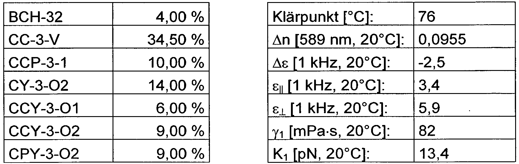

-
BCH-32 6,50 % CCH-23 16,00 % CCH-301 4,50 % CCH-34 8,00 % CCH-35 6,00 % CCP-3-1 8,50 % CY-3-O2 15,00 % CCY-3-O1 5,50 % CCY-3-O2 8,00 % CPY-3-O2 9,00 % PCH-302 4,50 % PY-V2-O2 8,50 % Klärpunkt [°C]: 76,5 Δn [589 nm, 20°C]: 0,0933 Δε [1 kHz, 20°C]: -2,5 ε∥ [1 kHz, 20°C]: 3,3 ε⊥ [1 kHz, 20°C]: 5,8 γ1 [mPa·s, 20°C]: 96 K1 [pN, 20°C]: 14,3 K3 [pN, 20°C]: 15,0 V0 [20°C, V]: 2,57 -


-
BCH-32 7,00 % CCH-23 16,00 % CCH-301 3,50 % CCH-34 6,50 % CCH-35 6,50 % CCP-3-1 9,50 % CY-3-O2 7,50 % CY-V1-O2 7,00 % CCY-3-O1 6,00 % CCY-3-O2 9,00 % CPY-3-O2 7,00 % PCH-302 5,00 % PY-V2-O2 9,50 % Klärpunkt [°C]: 75 Δn [589 nm, 20°C]: 0,0930 Δε [1 kHz, 20°C]: -2,5 ε∥ [1 kHz, 20°C]: 3,3 ε⊥ [1 kHz, 20°C]: 5,8 γ1 [mPa·s, 20°C]: 93 K1 [pN, 20°C]: 13,7 K3 [pN, 20°C]: 14,1 V0 [20°C, V]: 2,52 LTS (bulk) [-20°C] > 1000 h -


-
BCH-32 7,00 % CCH-23 13,00 % CCH-301 3,00 % CCH-34 10,00 % CCH-35 6,00 % CCP-3-1 10,50 % CY-3-O2 8,50 % CY-V1-O2 5,50 % CCY-3-O1 10,00 % CCY-3-O2 6,00 % CPY-1V-O1 5,50 % PCH-302 6,00 % PY-V2-O2 9,00 % Klärpunkt [°C]: 77 Δn [589 nm, 20°C]: 0,0935 Δε [1 kHz, 20°C]: -2,4 ε∥ [1 kHz, 20°C]: 3,3 ε⊥ [1 kHz, 20°C]: 5,7 γ1 [mPa·s, 20°C]: 97 K1 [pN, 20°C]: 14,1 K3 [pN, 20°C]: 14,6 V0 [20°C, V]: 2,62 -
CY-3-O2 9,50 % PY-V-O2 9,50 % CCY-3-O2 9,00 % CCY-4-O2 6,00 % CPY-2-O2 5,00 % CPY-3-O2 9,50 % CCH-34 10,00 % CCH-23 21,00 % PYP-2-3 7,00 % CCP-3-1 3,00 % PCH-301 10,50 % Klärpunkt [°C]: 75 Δn [589 nm, 20°C]: 0,1101 Δε [1 kHz, 20°C]: -3,0 ε∥ [1 kHz, 20°C]: 3,5 ε⊥ [1 kHz, 20°C]: 6,5 γ1 [mPa·s, 20°C]: 100 K1 [pN, 20°C]: 13,4 K3 [pN, 20°C]: 14,3 V0 [20°C, V]: 2,31 -
PY-3-O2 11,00 % PY-1V-O2 8,00 % CY-3-O2 5,00 % CCY-3-O2 9,00 % CCY-3-O1 6,00 % CPY-2-O2 7,00 % CPY-3-O2 10,00 % CCH-34 10,00 % CCH-23 21,00 % CCP-3-1 4,00 % PCH-301 9,00 % Klärpunkt [°C]: 75 Δn [589 nm, 20°C]: 0,1100 Δε [1 kHz, 20°C]: -3,4 ε∥ [1 kHz, 20°C]: 3,5 ε⊥ [1 kHz, 20°C]: 6,9 γ1 mPa·s, 20°C]: 107 K1 [pN, 20°C]: 14,3 K3 [pN, 20°C]: 15,2 V0 [20°C, V]: 2,24 -
CY-3-O2 10,00 % PY-V-O2 9,00 % CCY-3-O2 9,00 % CCY-4-O2 7,00 % CPY-2-O2 7,00 % CPY-3-O2 9,00 % CCH-34 11,00 % CCH-23 20,00 % PYP-2-3 7,00 % CCP-3-1 1,00 % PCH-301 10,00 % Klärpunkt [°C]: 75 Δn [589 nm, 20°C]: 0,1099 Δε [1 kHz, 20°C]: -3,2 ε∥ [1 kHz, 20°C]: 3,5 ε⊥ [1 kHz, 20°C]: 6,7 γ1 [mPa·s, 20°C]: 104 K1 [pN, 20°C]: 13,2 K3 [pN, 20°C]: 14,1 V0 [20°C, V]: 2,24 -


-
PY-3-O2 12,00 % PY-V-O2 5,00 % CCY-3-O2 10,00 % CCY-4-O2 9,50 % CPY-2-O2 6,00 % CPY-3-O2 9,00 % CCH-34 5,50 % CCH-23 21,00 % PYP-2-3 4,50 % CCH-35 4,00 % PCH-301 12,00 % BCH-32 1,50 % Klärpunkt [°C]: 75 Δn [589 nm, 20°C]: 0,1112 Δε [1 kHz, 20°C]: -3,1 ε∥ [1 kHz, 20°C]: 3,5 ε⊥ [1 kHz, 20°C]: 6,6 γ1 [mPa·s, 20°C]: 107 K1 [pN, 20°C]: 13,7 K3 [pN, 20°C]: 14,4 V0 [20°C, V]: 2,29 -


-
PY-3-O2 5,00 % PY-V2-O2 6,50 % CY-3-O2 12,00 % CCY-3-O1 5,00 % CCY-3-O2 10,00 % CPY-V-O2 9,00 % CPY-V-O4 10,00 % CC-3-V 35,00 % BCH-32 7,00 % PPGU-3-F 0,50 % Klärpunkt [°C]: 76 Δn [589 nm, 20°C]: 0,1082 Δε [1 kHz, 20°C]: -3,2 ε∥ [1 kHz, 20°C]: 3,7 ε⊥ [1 kHz, 20°C]: 6,9 γ1 [mPa·s, 20°C]: 89 K1 [pN, 20°C]: 12,6 K3 [pN, 20°C]: 14,6 V0 [20°C, V]: 2,26 - Die Mischung aus Beispiel 78 wird zusätzlich mit
0,01 % 
- Die Mischung aus Beispiel 78 wird zusätzlich mit
0,01 % 
-
PY-V-O2 5,00 % PY-V2-O2 5,00 % PY-3-O2 3,00 % CY-V-O2 4,00 % CY-3-O2 3,00 % CCY-3-O1 3,00 % CCY-3-O2 6,00 % CCY-4-O2 5,00 % CPY-2-O2 7,50 % CPY-3-O2 10,00 % CC-3-V 39,00 % BCH-32 7,00 % PPGU-3-F 0,50 % Y-4O-O4 2,00 % Klärpunkt [°C]: 73,5 Δn [589 nm, 20°C]: 0,1074 Δε [1 kHz, 20°C]: -2,9 ε∥ [1 kHz, 20°C]: 3,7 ε⊥ [1 kHz, 20°C]: 6,6 γ1 [mPa·s, 20°C]: 78 K1 [pN, 20°C]: 12,5 K3 [pN, 20°C]: 14,0 V0 [20°C, V]: 2,33 -


-
APUQU-2-F 9,00 % APUQU-3-F 8,50 % CC-3-V 43,50 % CCP-30CF3 7,50 % CCP-V-1 7,00 % DPGU-4-F 3,50 % PGP-2-2V 4,00 % PGUQU-4-F 4,50 % PUQU-3-F 8,50 % PY-3V-O2 4,00 % Klärpunkt [°C]: 77,5 Δn [589 nm, 20°C]: 0,1087 Δε [1 kHz, 20°C]: 9,9 ε∥ [1 kHz, 20°C]: 13,7 ε⊥ [1 kHz, 20°C]: 3,8 γ1 [mPa·s, 20°C]: 68 K1 [pN, 20°C]: 12,4 K3 [pN, 20°C]: 13,1 V0 [20°C, V]: 1,18 LTS (bulk) [-20°C]: > 1000 h LTS (bulk) [-30°C]: > 1000 h -


-
PY-V2-O2 5,50 % PY-3-O2 6,00 % CY-V2-O2 5,00 % CY-3-O2 4,00 % CCY-3-O1 3,00 % CCY-3-O2 3,00 % CCY-4-O2 6,00 % CPY-2-O2 8,00 % CPY-3-O2 12,00 % CC-3-V 36,50 % BCH-32 8,50 % PPGU-3-F 0,50 % Y-4O-O4 2,00 % Klärpunkt [°C]: 74 Δn [589 nm, 20°C]: 0,1074 Δε [1 kHz, 20°C]: -2,9 ε∥ [1 kHz, 20°C]: 3,7 ε⊥ [1 kHz, 20°C]: 6,6 γ1 [mPa·s, 20°C]: 85 K1 [pN, 20°C]: 12,6 K3 [pN, 20°C]: 13,9 V0 [20°C, V]: 2,30 -
PY-V2-O2 6,00 % PY-3-O2 6,00 % CY-1V2-O2 4,50 % CY-3-O2 4,00 % CCY-3-O1 3,00 % CCY-3-O2 3,00 % CCY-4-O2 6,00 % CPY-2-O2 8,00 % CPY-3-O2 12,00 % CC-3-V 37,00 % BCH-32 8,00 % PPGU-3-F 0,50 % Y-4O-O4 2,00 % Klärpunkt [°C]: 74,5 Δn [589 nm, 20°C]: 0,1086 Δε [1 kHz, 20°C]: -2,9 ε∥ [1 kHz, 20°C]: 3,6 ε⊥ [1 kHz, 20°C]: 6,5 γ1 [mPa·s, 20°C]: 86 K1 [pN, 20°C]: 12,8 K3 [pN, 20°C]: 14,2 V0 [20°C, V]: 2,33 -
PY-V2-O2 6,50 % CY-3-O2 11,00 % CY-V2-O2 6,50 % CCY-3-O1 6,00 % CCY-3-O2 2,00 % CPY-2-O2 10,00 % CPY-3-O2 12,00 % CC-3-V 36,00 % BCH-32 9,50 % PPGU-3-F 0,50 % Klärpunkt [°C]: 74 Δn [589 nm, 20°C]: 0,1068 Δε [1 kHz, 20°C]: -2,8 ε∥ [1 kHz, 20°C]: 3,6 ε⊥ [1 kHz, 20°C]: 6,4 γ1 [mPa·s, 20°C]: 85 K1 [pN, 20°C]: 12,3 K3 [pN, 20°C]: 14,1 V0 [20°C, V]: 2,35 -
PCH-504FF 10,00 % PCH-502FF 8,00 % PCH-304FF 4,00 % CCP-V2-1 6,00 % BCH-32 7,00 % CCH-35 5,00 % CC-5-V 7,00 % CC-3-V1 10,00 % CPY-2-O2 10,00 % CPY-3-O2 13,00 % PY-V2-O2 20,00 % Klärpunkt [°C]: 72 Δn [589 nm, 20°C]: 0,1216 Δε [1 kHz, 20°C]: -4,0 ε∥ [1 kHz, 20°C]: 3,9 ε⊥ [1 kHz, 20°C]: 7,9 γ1 [mPa·s, 20°C]: 125 K1 [pN, 20°C]: 14,6 K3 [pN, 20°C]: 14,7 V0 [20°C, V]: 2,03 -


-
CY-3-O2 18,00 % PY-1V2-O2 6,00 % CCY-3-O2 8,00 % CCY-4-O2 4,00 % CPY-2-O2 7,00 % CPY-3-O2 10,00 % CCH-34 8,00 % CCH-23 22,00 % CCP-3-3 7,00 % CCP-3-1 7,00 % PCH-301 3,00 % Klärpunkt [°C]: 80,5 Δn [589 nm, 20°C]: 0,0949 Δε [1 kHz, 20°C]: -3,1 ε∥ [1 kHz, 20°C]: 3,4 ε⊥ [1 kHz, 20°C]: 6,4 γ1 [mPa·s, 20°C]: 113 K1 [pN, 20°C]: 14,9 K3 [pN, 20°C]: 16,0 V0 [20°C, V]: 2,41 LTS (bulk) [-20°C]: > 1000 h -
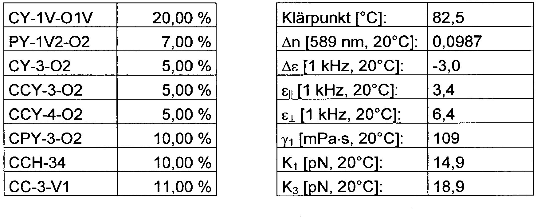

-
CY-1V-O1V 20,00 % PY-1V2-O2 5,00 % CY-3-O2 7,00 % CCY-3-O2 6,00 % CCY-3-O1 6,00 % CPY-3-O2 8,00 % CCH-34 10,00 % CC-3-V1 11,00 % CC-2-V1 11,00 % CCP-3-1 8,00 % PCH-301 2,00 % CCVC-3-V 6,00 % Klärpunkt [°C]: 81 Δn [589 nm, 20°C]: 0,0953 Δε [1 kHz, 20°C]: -3,0 ε∥ [1 kHz, 20°C]: 3,4 ε⊥ [1 kHz, 20°C]: 6,4 γ1 [mPa·s, 20°C]: 106 K1 [pN, 20°C]: 14,5 K3 [pN, 20°C]: 18,6 V0 [20°C, V]: 2,63 LTS (bulk) [-20°C]: > 1000 h -


-
CY-1V-O1V 20,00 % PY-1V2-O2 5,00 % CY-3-O2 12,00 % CCY-3-O2 6,00 % CCY-4-O2 6,00 % CPY-3-O2 8,00 % CCH-34 7,00 % CC-3-V1 11,00 % CC-2-V1 11,00 % CCP-3-1 6,00 % CCVC-3-V 8,00 % Klärpunkt [°C]: 80,5 Δn [589 nm, 20°C]: 0,0962 Δε [1 kHz, 20°C]: -3,4 ε∥ [1 kHz, 20°C]: 3,5 ε⊥ [1 kHz, 20°C]: 6,9 γ1 [mPa·s, 20°C]: 112 K1 [pN, 20°C]: 14,3 K3 [pN, 20°C]: 18,5 V0 [20°C, V]: 2,45 -
CY-1V-O1V 20,00 % PY-1V2-O2 7,00 % CY-3-O2 7,50 % CCY-3-O2 10,50 % CCY-4-O2 10,00 % CC-3-V2 11,00 % CC-3-V1 11,00 % CC-2-V1 11,00 % CCP-3-1 6,00 % CCVC-3-V 6,00 % Klärpunkt [°C]: 81,5 Δn [589 nm, 20°C]: 0,0932 Δε [1 kHz, 20°C]: -3,3 ε∥ [1 kHz, 20°C]: 3,4 ε⊥ [1 kHz, 20°C]: 6,7 γ1 [mPa·s, 20°C]: 104 K1 [pN, 20°C]: 14,9 K3 [pN, 20°C]: 19,0 V0 [20°C, V]: 2,55 LTS (bulk) [-20°C] > 1000 h -
CY-3-O2 12,00 % PY-1V2-O2 11,00 % CCY-3-O2 10,00 % CCY-4-O2 10,00 % CPY-3-O2 10,00 % CCH-34 8,00 % CCH-23 22,00 % CCP-3-3 3,00 % CCP-3-1 7,00 % PCH-301 7,00 % Klärpunkt [°C]: 80,0 Δn [589 nm, 20°C]: 0,0950 Δε [1 kHz, 20°C]: -3,1 ε∥ [1 kHz, 20°C]: 3,3 ε⊥ [1 kHz, 20°C]: 6,4 γ1 [mPa·s, 20°C]: 111 K1 [pN, 20°C]: 15,1 K3 [pN, 20°C]: 16,6 V0 [20°C, V]: 2,46 LTS (bulk) [-20°C] > 1000 h -
CY-1V-O1V 18,00 % PY-1V2-O2 4,00 % CY-3-O2 15,00 % CCY-3-O2 8,00 % CCY-4-O2 7,00 % CPY-3-O2 7,00 % CCH-34 7,00 % CC-3-V1 11,00 % CC-2-V1 11,00 % CCP-3-1 3,00 % CCVC-3-V 9,00 % Klärpunkt [°C]: 80,5 Δn [589 nm, 20°C]: 0,0943 Δε [1 kHz, 20°C]: -3,6 ε∥ [1 kHz, 20°C]: 3,5 ε⊥ [1 kHz, 20°C]: 7,2 γ1 [mPa·s, 20°C]: 112 K1 [pN, 20°C]: 14,2 K3 [pN, 20°C]: 18,2 V0 [20°C, V]: 2,37 -


-
PY-3-O2 11,00 % PY-V2-O2 6,50 % CCY-3-O2 9,00 % CCY-4-O2 3,00 % CCY-3-O1 5,00 % CPY-2-O2 6,50 % CPY-3-O2 10,00 % CCH-34 10,00 % CCH-23 21,00 % PYP-2-3 6,00 % CCP-3-1 3,00 % PCH-301 9,00 % Klärpunkt [°C]: 75 Δn [589 nm, 20°C]: 0,1105 Δε [1 kHz, 20°C]: -3,1 ε∥ [1 kHz, 20°C]: 3,5 ε⊥ [1 kHz, 20°C]: 6,6 γ1 [mPa·s, 20°C]: 105 K1 [pN, 20°C]: 13.9 K3 [pN, 20°C]: 14,3 V0 [20°C, V]: 2,28 LTS (bulk) [-20°C] > 1000 h -


-
PY-3-O2 11,00 % PY-1V2-O2 8,00 % CY-3-O2 3,00 % CCY-3-O2 9,00 % CCY-3-O1 6,00 % CPY-2-O2 6,50 % CPY-3-O2 10,00 % CCH-34 10,00 % CCH-23 21,00 % PYP-2-3 5,00 % CCP-3-1 4,00 % PCH-301 6,50 % Klärpunkt [°C]: 74 Δn [589 nm, 20°C]: 0,1119 Δε [1 kHz, 20°C]: -3,3 ε∥ [1 kHz, 20°C]: 3,5 ε⊥ [1 kHz, 20°C]: 6,8 γ1 [mPa·s, 20°C]: 108 K1 [pN, 20°C]: 14,3 K3 [pN, 20°C]: 15,0 V0 [20°C, V]: 2,26 LTS (bulk) [-20°C] > 1000 h -
CC-3-V 39,00 % CC-3-V1 3,00 % CCP-V-1 8,00 % CCP-V2-1 12,00 % PGP-2-2V 3,50 % PP-1-2V1 9,00 % PPGU-3-F 1,00 % PUQU-3-F 15,50 % CCY-3-O2 9,00 % Klärpunkt [°C]: 74,5 Δn [589 nm, 20°C]: 0,1017 Δε [1 kHz, 20°C]: 3,2 γ1 [mPa·s, 20°C]: 64 K1 [pN, 20°C]: 13 K3 [pN, 20°C]: 15,4 V0 [20°C, V]: 2,13 -
BCH-32 5,00 % CC-3-V 41,50 % CC-3-V1 8,50 % CCH-35 2,00 % CCP-3-1 3,00 % CCY-3-O2 7,00 % CPY-2-O2 5,50 % CPY-3-O2 12,50 % PY-3-O2 15,00 % Klärpunkt [°C]: 75,3 Δn [589 nm, 20°C]: 0,0989 Δε [1 kHz, 20°C]: -1,9 ε∥ [1 kHz, 20°C]: 3,2 ε⊥ [1 kHz, 20°C]: 5,0 γ1 [mPa·s, 20°C]: 69 K1 [pN, 20°C]: 14,2 K3 [pN, 20°C]: 15,5 V0 [20°C, V]: 3,02 - Die Mischung aus Beispiel 101 wird zusätzlich mit 0,001 % Irganox® 1076 (Octadecyl-3-(3,5-di-tert. butyl-4-hydroxyphenyl)-proprionat, Fa. BASF) und 0,3 % RM-1 versetzt.
-
CCY-3-O1 8,00 % CCY-4-O2 7,50 % CPY-2-O2 10,00 % CPY-3-O2 10,00 % CC-3-V 15,00 % PY-1-O4 5,00 % PY-3-O2 9,00 % PY-4-O2 5,00 % CC-3-V1 9,00 % CCY-3-O2 6,50 % PCH-301 15,00 % Klärpunkt [°C]: 74,9 Δn [589 nm, 20°C]: 0,1123 Δε [1 kHz, 20°C]: -3,7 ε∥ [1 kHz, 20°C]: 3,7 ε⊥ [1 kHz, 20°C]: 7,5 γ1 [mPa·s, 20°C]: 121 K1 [pN, 20°C]: 13,2 K3 [pN, 20°C]: 15,5 V0 [20°C, V]: 2,15 - Die Mischung aus Beispiel 102 wird zusätzlich mit
0,01 % 
-
CY-3-O2 10,00 % CY-3-O4 20,00 % CY-5-O4 20,00 % CCY-3-O2 6,00 % CCY-3-O3 6,00 % CCY-4-O2 6,00 % CCY-5-O2 6,00 % CH-33 3,00 % CH-35 3,50 % CH-43 3,50 % CH-45 3,50 % CCPC-33 4,00 % CCPC-34 4,50 % CCPC-35 4,00 % Klärpunkt [°C]: 100 Δn [589 nm, 20°C]: 0,0865 Δε [1 kHz, 20°C]: -5,4 ε∥ [1 kHz, 20°C]: 3,9 ε⊥ [1 kHz, 20°C]: 9,3 γ1 [mPa·s, 20°C]: 347 K1 [pN, 20°C]: 15,6 K3 [pN, 20°C]: 16,6 V0 [20°C, V]: 1,84 -
CY-3-O2 15,00 % CY-5-O2 12,00 % CCH-3-O1 4,00 % CCY-3-O2 4,00 % CCY-3-O3 4,00 % CCY-4-O2 4,00 % CLY-3-O2 10,00 % CLY-3-O3 2,00 % CPY-2-O2 8,00 % CC-3-V 24,00 % PGP-2-5 5,00 % Klärpunkt [°C]: 91 Δn [589 nm, 20°C]: 0,105 Δε [1 kHz, 20°C]: -4,5 γ1 [mPa·s, 20°C]: 106 V0 [20°C, V]: 1,32 -
CY-3-O2 14,00 % CY-3-O4 4,00 % CY-5-O2 7,00 % CCH-3-O1 4,00 % CCY-3-O2 5,00 % CCY-4-O2 8,00 % CCY-5-O2 3,00 % CPY-2-O2 9,00 % CPY-3-O2 9,00 % PYP-2-3 6,00 % CC-3-V 22,00 % CC-3-V1 3,50 % CCP-V-1 5,00 % PPGU-3-F 0,50 % Klärpunkt [°C]: 84,7 Δn [589 nm, 20°C]: 0,1068 Δε [1 kHz, 20°C]: -4,0 γ1 [mPa·s, 20°C]: 138 K1 [pN, 20°C]: 14,1 K3 [pN, 20°C]: 16,2 V0 [20°C, V]: 2,13 -
CY-3-O2 15,00 % CY-5-O2 12,50 % CCH-3-O1 2,50 % CCY-4-O2 5,00 % CPY-2-O2 8,00 % CPY-3-O2 8,00 % CCY-2-1 6,00 % CCY-3-1 6,00 % CCH-23 15,00 % CCH-34 5,00 % CCH-301 1,50 % BCH-32 15,50 % Klärpunkt [°C]: 80,4 Δn [589 nm, 20°C]: 0,1038 Δε [1 kHz, 20°C]: -3,3 ε∥ [1 kHz, 20°C]: 3,5 ε⊥ [1 kHz, 20°C]: 6,8 γ1 [mPa·s, 20°C]: 137 K1 [pN, 20°C]: 14,2 K3 [pN, 20°C]: 14,2 V0 [20°C, V]: 2,18 - Die Mischung aus Beispiel 106 wird zusätzlich mit 0,25 % RM-35 versetzt.

0,025 % 
-
CC-3-V 34,00 % CC-3-V1 2,50 % CCP-V-1 10,00 % PUQU-3-F 7,00 % PGUQU-3-F 4,00 % CPGU-3-OT 6,00 % CCGU-3-F 4,00 % APUQU-3-F 8,00 % CCP-3F.F.F 4,50 % CCP-30CF3 4,00 % CCP-50CF3 3,00 % CCQU-3-F 10,00 % CBC-33 3,00 % Klärpunkt [°C]: 100 Δn [589 nm, 20°C]: 0,1003 Δε [1 kHz, 20°C]: 9,1 ε∥ [1 kHz, 20°C]: 12,3 ε⊥ [1 kHz, 20°C]: 3,2 γ1 [mPa·s, 20°C]: 99 K1 [pN, 20°C]: 14,2 K3 [pN, 20°C]: 17,3 - Die Mischung aus Beispiel 107 wird zusätzlich mit
0,03 % 
- Die Mischung aus Beispiel 107 wird zusätzlich mit
0,03 % 
-
Y-4O-O4 4,50 % PYP-2-3 2,00 % CC-3-V 25,00 % CC-4-V 10,00 % CCP-V-1 14,00 % PTP-302FF 10,00 % CPTP-302FF 10,00 % CPTP-302FF 10,00 % PPTUI-3-2 14,50 % Klärpunkt [°C]: 100 Δn [589 nm, 20°C]: 0,1716 Δε [1 kHz, 20°C]: -1,5 ε∥ [1 kHz, 20°C]: 3,4 ε⊥ [1 kHz, 20°C]: 4,9 γ1 [mPa·s, 20°C]: 114 K1 [pN, 20°C]: 15,2 K3 [pN, 20°C]: 18,5 V0 [20°C, V]: 3,76 -
CCH-23 25,00 % CC-3-V 4,50 % PCH-53 25,00 % CCY-2-1 12,00 % CCY-3-1 12,00 % CCY-3-O2 12,00 % CCY-3-O3 5,00 % CBC-33F 4,50 % Klärpunkt [°C]: 70,3 Δn [589 nm, 20°C]: 0,0737 Δε [1 kHz, 20°C]: -1,1 ε∥ [1 kHz, 20°C]: 2,8 ε⊥ [1 kHz, 20°C]: 3,9 K1 [pN, 20°C]: 11,7 K3 [pN, 20°C]: 13,1 -
CC-3-V1 10,25 % CCH-23 18,50 % CCH-35 6,75 % CCP-3-1 6,00 % CCY-3-1 2,50 % CCY-3-O2 12,00 % CPY-2-O2 6,00 % CPY-3-O2 9,75 % CY-3-O2 11,50 % PP-1-2V1 3,75 % PY-3-O2 13,00 % Klärpunkt [°C]: 74,7 Δn [589 nm, 20°C]: 0,1027 Δε [1 kHz, 20°C]: -3,1 ε∥ [1 kHz, 20°C]: 3,4 ε⊥ [1 kHz, 20°C]: 6,5 γ1 [mPa·s, 20°C]: 104 K1 [pN, 20°C]: 15,4 K3 [pN, 20°C]: 16,8 V0 [20°C, V]: 2,46 - Die Mischung aus Beispiel 101 wird zusätzlich mit 0,01 % Irganox® 1076 (Octadecyl-3-(3,5-di-tert. butyl-4-hydroxyphenyl)-proprionat, Fa. BASF) und 0,3 % RM-1 versetzt.
-
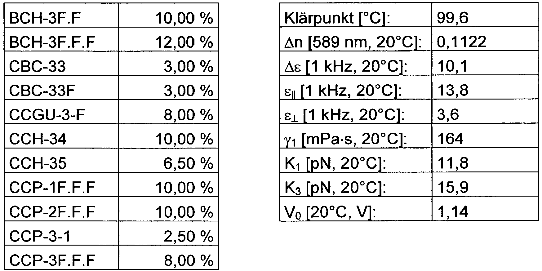
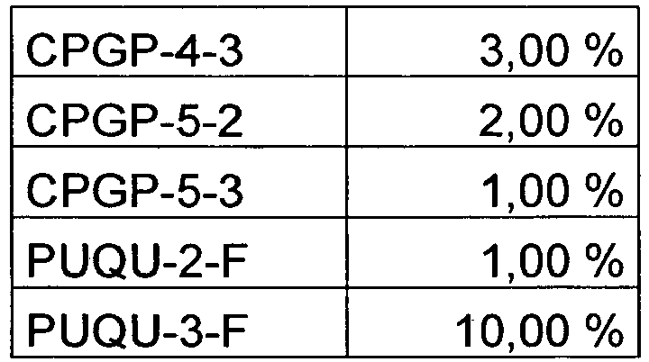
-
CBC-53F 3,00 % CC-3-2V1 1,00 % CC-3-V 25,00 % CC-3-V1 5,00 % CCGU-3-F 5,50 % CCP-30CF3 4,00 % CCP-30CF3.F 8,00 % CCP-40CF3 3,00 % CCP-50CF3 3,00 % CCP-V-1 8,00 % CCP-V2-1 12,00 % CPGU-3-OT 5,00 % PGUQU-3-F 4,00 % PGUQU-4-F 4,00 % PGUQU-5-F 2,00 % PP-1-2V1 3,00 % PPGU-3-F 0,50 % PUQU-2-F 1,00 % PUQU-3-F 3,00 % Klärpunkt [°C]: 115,5 Δn [589 nm, 20°C]: 0,1106 Δε [1 kHz, 20°C]: 7,0 ε∥ [1 kHz, 20°C]: 9,9 ε1 [1 kHz, 20°C]: 2,9 γ1 [mPa·s, 20°C]: 118 K1 [pN, 20°C]: 17,4 K3 [pN, 20°C]: 20,4 V0 [20°C, V]: 1,66 -


-
APUQU-2-F 2,50 % APUQU-3-F 5,00 % PUQU-3-F 12,50 % PGUQU-3-F 5,00 % PGUQU-4-F 4,00 % PGUQU-5-F 4,00 % DPGU-4-F 4,00 % PPGU-3-F 0,50 % CDUQU-3-F 0,05 % CC-3-V 34,95 % CCP-V-1 7,00 % CCP-V2-1 6,00 % CCP-3-1 2,50 % CCPC-33 2,00 % CY-3-O2 5,00 % CCY-3-O2 5,00 % Klärpunkt [°C]: 85,8 Δn [589 nm, 20°C]: 0,1105 Δε [1 kHz, 20°C]: 10,6 ε∥ [1 kHz, 20°C]: 14,8 ε⊥ [1 kHz, 20°C]: 4,2 γ1 [mPa·s, 20°C]: 98 K1 [pN, 20°C]: 12,7 K3 [pN, 20°C]: 15,1 -
APUQU-2-F 3,00 % APUQU-3-F 5,00 % PUQU-3-F 12,00 % PGUQU-3-F 5,00 % PGUQU-4-F 4,00 % PGUQU-5-F 3,00 % PPGU-3-F 0,50 % CDUQU-3-F 0,05 % CC-3-V 38,95 % CCP-V-1 10,50 % CCP-V2-1 9,00 % PGP-2-3 2,00 % CCY-3-O2 3,50 % CPY-3-O2 3,50 % Klärpunkt [°C]: 85,7 Δn [589 nm, 20°C]: 0,1097 Δε [1 kHz, 20°C]: 8,7 ε∥ [1 kHz, 20°C]: 12,4 ε⊥ [1 kHz, 20°C]: 3,7 γ1 [mPa·s, 20°C]: 82 K1 [pN, 20°C]: 12,9 K3 [pN, 20°C]: 15,7 V0 [20°C, V]: 1,29 -
APUQU-2-F 3,00 % APUQU-3-F 5,00 % PUQU-3-F 12,00 % PGUQU-3-F 5,00 % PGUQU-4-F 4,00 % PGUQU-5-F 3,00 % PPGU-3-F 0,50 % CDUQU-3-F 0,05 % CC-3-V 38,95 % CCP-V-1 10,50 % CCP-V2-1 9,00 % PGP-2-3 2,00 % CCY-3-O2 3,50 % CPY-3-O2 3,50 % Klärpunkt [°C]: 85,7 Δn [589 nm, 20°C]: 0,1097 Δε [1 kHz, 20°C]: 8,7 ε∥ [1 kHz, 20°C]: 12,4 ε⊥ [1 kHz, 20°C]: 3,7 γ1 [mPa·s, 20°C]: 82 K1 [pN, 20°C]: 12,9 K3 [pN, 20°C]: 15,7 V0 [20°C, V]: 1,29 -
CC-3-V 35,00 % CCY-3-O1 9,00 % CCY-3-O2 8,00 % CCY-4-O2 5,00 % CLY-3-O3 11,00 % CPY-2-O2 9,50 % CPY-3-O2 4,00 % CY-3-O2 6,50 % PY-3-O2 12,00 % Klärpunkt [°C]: 84,6 Δn [589 nm, 20°C]: 0,1010 Δε [1 kHz, 20°C]: -4,0 ε∥ [1 kHz, 20°C]: 3,6 ε⊥ [1 kHz, 20°C]: 7,6 γ1 [mPa·s, 20°C]: 114 K1 [pN, 20°C]: 14,5 - Die Mischung aus Beispiel 117 wird zusätzlich mit
0,04 % 
0,015 % 
-
CC-3-V 33,00 % CCH-3-O1 7,00 % CCY-3-O2 7,00 % CCY-4-O2 5,00 % CLY-3-O3 11,00 % CPY-2-O2 9,00 % CPY-3-O2 8,00 % PP-1-2V1 1,50 % PY-1-O4 8,50 % PY-3-O2 10,00 % Klärpunkt [°C]: 84 Δn [589 nm, 20°C]: 0,1111 Δε [1 kHz, 20°C]: -4,0 ε∥ [1 kHz, 20°C]: 3,7 ε⊥ [1 kHz, 20°C]: 7,6 γ1 [mPa·s, 20°C]: 119 K1 [pN, 20°C]: 14,8 - Die Mischung aus Beispiel 118 wird zusätzlich mit
0,04 % 
0,015 % 
-
APUQU-2-F 4,00 % APUQU-3-F 7,00 % PUQU-3-F 5,00 % PGUQU-3-F 4,00 % PGUQU-4-F 3,00 % PGUQU-5-F 3,00 % CCP-V-1 16,00 % CC-3-V 40,00 % CC-3-V1 4,00 % CC-4-V 3,00 % PGP-2-3 4,00 % PGP-2-4 1,00 % PPGU-3-F 1,00 % CCOC-4-3 5,00 % Klärpunkt [°C]: 85,6 Δn [589 nm, 20°C]: 0,1021 Δε [1 kHz, 20°C]: 6,9 ε∥ [1 kHz, 20°C]: 10,0 ε⊥ [1 kHz, 20°C]: 3,1 γ1 [mPa·s, 20°C]: 71 K1 [pN, 20°C]: 13,1 K3 [pN, 20°C]: 15,3 V0 [20°C, V]: 1,45 - Die Mischung aus Beispiel 119 wird zusätzlich mit 0,25 % RM-41
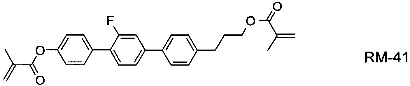
- Die Mischung aus Beispiel 119 wird zusätzlich mit 0,3 % RM-17

-
Y-4O-O4 12,00 % CY-3-O2 14,00 % CCH-3-O1 5,00 % CCY-3-O2 6,00 % CCY-3-O3 6,00 % CCY-4-O2 6,00 % CPY-2-O2 2,50 % PTP-302FF 10,00 % CPTP-302FF 10,00 % CPTP-502FF 10,00 % CC-4-V 2,50 % CCP-V-1 11,50 % CCPC-33 4,50 % Klärpunkt [°C]: 101 Δn [589 nm, 20°C]: 0,1504 Δε [1 kHz, 20°C]: -6,2 ε∥ [1 kHz, 20°C]: 4,5 ε⊥ [1 kHz, 20°C]: 10,7 γ1 [mPa·s, 20°C]: 281 K1 [pN, 20°C]: 15,7 K3 [pN, 20°C]: 19,9 V0 [20°C, V]: 1,90 -
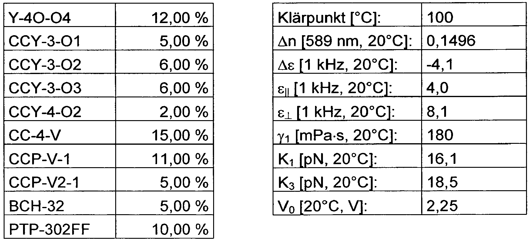

-
Y-4O-O4 10,00 % CCH-3-O1 2,50 % PTP-302FF 10,00 % PTP-502FF 3,50 % CPTP-302FF 10,00 % CPTP-502FF 3,50 % CC-4-V 15,00 % CC-3-V1 8,00 % CCP-V-1 12,00 % CCP-V2-1 12,00 % BCH-32 5,00 % CPTP-3-1 5,00 % CPTP-3-2 3,50 % Klärpunkt [°C]: 100 Δn [589 nm, 20°C]: 0,1515 Δε [1 kHz, 20°C]: -2,1 ε∥ [1 kHz, 20°C]: 3,5 ε⊥ [1 kHz, 20°C]: 5,6 γ1 [mPa·s, 20°C]: 125 K1 [pN, 20°C]: 16,6 K3 [pN, 20°C]: 18,7 V0 [20°C, V]: 3,13 -

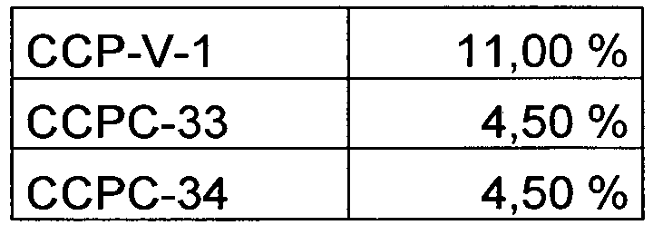
-
Y-4O-O4 15,00 % CCY-3-O2 5,00 % CCY-3-O3 5,00 % CCY-4-O2 5,00 % CLY-3-O2 4,00 % CPY-2-O2 8,00 % CPY-3-O2 8,00 % CPTP-302FF 5,00 % CPTP-502FF 5,00 % CC-4-V 13,50 % CCP-V-1 11,50 % CCP-V2-1 10,00 % BCH-32 5,00 % Klärpunkt [°C]: 101 Δn [589 nm, 20°C]: 0,1216 Δε [1 kHz, 20°C]: -4,0 ε∥ [1 kHz, 20°C]: 4,0 ε⊥ [1 kHz, 20°C]: 8,0 γ1 [mPa·s, 20°C]: 167 K1 [pN, 20°C]: 16,1 K3 [pN, 20°C]: 17,3 V0 [20°C, V]: 2,19 -


-
BCH-32 16,00 % BCH-52 6,50 % CCH-3-O1 5,00 % CCY-3-O2 8,00 % CCY-3-O3 6,00 % CCY-4-O2 8,00 % CCY-5-O2 7,00 % CY-3-O4 13,00 % PY-3-O2 5,50 % PY-4-O2 9,00 % PYP-2-3 8,00 % PYP-2-4 8,00 % Klärpunkt [°C]: 10,5 Δn [589 nm, 20°C]: 0,1503 Δε [1 kHz, 20°C]: -4,2 ε∥ [1 kHz, 20°C]: 3,8 ε⊥ [1 kHz, 20°C]: 8,0 γ1 [mPa·s, 20°C]: 297 K1 [pN, 20°C]: 18,3 K3 [pN, 20°C]: 17,3 V0 [20°C, V]: 2,13 - Die Mischung aus Beispiel 126 wird zusätzlich mit
0,015 % 
0,015 % 
-
CC-3-V 35,50 % CCY-3-O2 6,00 % CCY-3-O3 6,00 % CCY-4-O2 6,00 % CCY-5-O2 3,50 % CPY-2-O2 10,00 % CPY-3-O2 9,00 % CY-3-O4 10,00 % CY-5-O2 9,00 % PGIGI-3-F 5,00 % Klärpunkt [°C]: 79,8 Δn [589 nm, 20°C]: 0,0962 Δε [1 kHz, 20°C]: -3,4 ε∥ [1 kHz, 20°C]: 3,6 ε⊥ [1 kHz, 20°C]: 7,0 γ1 [mPa·s, 20°C]: 111 K1 [pN, 20°C]: 13,3 K3 [pN, 20°C]: 15,2 V0 [20°C, V]: 2,23 -


-
CC-3-V 36,50 % CCP-V-1 3,00 % CCY-3-O1 6,50 % CCY-3-O2 3,50 % CCH-4-O2 5,00 % CLY-3-O3 9,00 % CPY-2-O2 11,00 % CPY-3-O2 9,00 % CY-3-O2 3,00 % PY-3-O2 13,50 % Klärpunkt [°C]: 84,9 Δn [589 nm, 20°C]: 0,1054 Δε [1 kHz, 20°C]: -3,5 ε∥ [1 kHz, 20°C]: 3,5 ε⊥ [1 kHz, 20°C]: 7,0 γ1 [mPa·s, 20°C]: 108 K1 [pN, 20°C]: 14,4 K3 [pN, 20°C]: 15,7 V0 [20°C, V]: 2,24 -
CC-3-V 39,00 % BCH-3F.F.F 8,00 % PGU-2-F 6,00 % PGU-3-F 6,00 % APUQU-2-F 6,00 % APUQU-3-F 8,00 % PGUQU-3-F 6,00 % PGUQU-4-F 6,00 % PGUQU-5-F 6,00 % DPGU-4-F 9,00 % Klärpunkt [°C]: 75,2 Δn [589 nm, 20°C]: 0,1298 Δε [1 kHz, 20°C]: 18,3 ε∥ [1 kHz, 20°C]: 22,6 ε⊥ [1 kHz, 20°C]: 4,3 γ1 [mPa·s, 20°C]: 99 K1 [pN, 20°C]: 10,9 K3 [pN, 20°C]: 11,1 V0 [20°C, V]: 0,81 -
CC-3-V 38,50 % CCH-3-O1 4,50 % CCY-3-O2 4,00 % CCY-4-O2 8,00 % CLY-3-O2 8,00 % CPY-2-O2 10,00 % CPY-3-O2 9,00 % PY-1-O4 7,50 % PY-3-O2 6,00 % Y-4O-O4 4,50 % Klärpunkt [°C]: 74,9 Δn [589 nm, 20°C]: 0,1012 Δε [1 kHz, 20°C]: -3,7 ε∥ [1 kHz, 20°C]: 3,7 ε⊥ [1 kHz, 20°C]: 7,4 γ1 [mPa·s, 20°C]: 94 K1 [pN, 20°C]: 13,4 K3 [pN, 20°C]: 14,4 V0 [20°C, V]: 2,08 LTS (bulk) [-20°C] > 1000 h - Die Mischung aus Beispiel 131 wird zusätzlich mit
0,25 % 
RM-41 0,25 % 
RM-35 -


- Die Mischung aus Beispiel 132 wird zusätzlich mit
0,04 % 
0,02 % 
-


- Die Mischung aus Beispiel 133 wird zusätzlich mit
0,25 % 
RM-41 -
CY-3-O2 18,50 % CCY-3-O2 11,00 % CCY-4-O2 9,00 % CPY-2-O2 7,50 % CPY-3-O2 9,00 % CCH-34 9,00 % CCH-35 9,00 % CC-3-V 10,00 % CCH-301 9,00 % CCH-303 5,00 % PYP-2-3 3,00 % Klärpunkt [°C]: 80 Δn [589 nm, 20°C]: 0,0896 Δε [1 kHz, 20°C]: -3,4 ε∥ [1 kHz, 20°C]: 3,5 ε⊥ kHz, 20°C]: 6,9 γ1 [mPa·s, 20°C]: 117 K1 [pN, 20°C]: 14,4 K3 [pN, 20°C]: 15,1 V0 [20°C, V]: 2,23 - Die Mischung aus Beispiel 134 wird zusätzlich mit
0,2 % 
RM-1 -
CY-3-O2 10,50 % PY-1-O4 5,00 % PY-3-O2 7,50 % PY-4-O2 4,00 % CCH-3-O1 5,50 % CCY-3-O2 5,00 % CCY-4-O2 4,00 % CLY-3-O2 9,00 % CPY-2-O2 9,00 % CPY-3-O2 9,00 % CC-3-V 23,50 % CC-3-V1 7,00 % CBC-33F 1,00 % Klärpunkt [°C]: 79,7 Δn [589 nm, 20°C]: 0,1113 Δε [1 kHz, 20°C]: -4,4 K1 [pN, 20°C]: 14,5 K3 [pN, 20°C]: 16,7 V0 [20°C, V]: 2,05 -


-
CC-3-V 27,00 % CCY-3-1 9,50 % CCP-3-1 8,00 % CLY-3-O2 6,00 % CPY-2-O2 10,50 % CPY-3-O2 10,50 % CY-3-O2 15,00 % PY-3-O2 13,50 % Klärpunkt [°C]: 74,9 Δn [589 nm, 20°C]: 0,1093 Δε [1 kHz, 20°C]: -3,8 ε∥ [1 kHz, 20°C]: 3,7 ε⊥ [1 kHz, 20°C]: 7,5 γ1 [mPa·s, 20°C]: 108 K1 [pN, 20°C]: 14,1 K3 [pN, 20°C]: 15,8 V0 [20°C, V]: 2,16 -


- Die Mischung aus Beispiel 138 wird zusätzlich mit
0,04 % 
-
CCH-23 12,00 % CCH-34 10,00 % CCP-3-1 7,00 % CCY-3-1 10,00 % CCH-3-O1 1,50 % CCY-3-O2 9,00 % CCY-3-O3 7,50 % CCY-4-O2 9,00 % CPGP-4-3 2,00 % CPY-2-O2 8,00 % CPY-3-O2 8,00 % CY-3-O2 1,50 % CY-3-O4 3,00 % PCH-301 10,00 % PYP-2-3 1,50 % Klärpunkt [°C]: 110,7 Δn [589 nm, 20°C]: 0,1002 Δε [1 kHz, 20°C]: -2,9 ε∥ [1 kHz, 20°C]: 3,2 ε⊥ [1 kHz, 20°C]: 6,1 γ1 [mPa·s, 20°C]: 147 K1 [pN, 20°C]: 17,3 K3 [pN, 20°C]: 18,3 V0 [20°C, V]: 2,65 - Die Mischung aus Beispiel 139 wird zusätzlich mit
0,04 %
-
BCH-32 1,50 % CC-3-V 19,50 % CC-3-V1 5,50 % CCP-3-1 8,00 % CCP-3-3 4,50 % CLY-3-O2 6,00 % CPY-2-O2 10,50 % CPY-3-O2 10,50 % CY-3-O2 15,00 % CY-5-O2 9,00 % PY-3-O2 10,00 % Klärpunkt [°C]: 74,3 Δn [589 nm, 20°C]: 0,1089 Δε [1 kHz, 20°C]: -3,8 ε∥ [1 kHz, 20°C]: 3,7 ε⊥ [1 kHz, 20°C]: 7,5 γ1 [mPa·s, 20°C]: 115 K1 [pN, 20°C]: 13,7 K3 [pN, 20°C]: 16,1 V0 [20°C, V]: 2,18 -


-
PGUQU-3-F 5,00 % CCQU-3-F 8,00 % CCQU-5-F 4,00 % PUQU-3-F 13,50 % APUQU-2-F 3,00 % APUQU-3-F 6,00 % CC-3-V 25,50 % CC-3-V1 6,00 % CCP-V-1 13,00 % CCP-V2-1 6,00 % PPGU-3-F 0,50 % BCH-3F.F 7,50 % BCH-2F.F 2,00 % Klärpunkt [°C]: 84,8 Δn [589 nm, 20°C]: 0,1035 Δε [1 kHz, 20°C]: 10,1 ε∥ [1 kHz, 20°C]: 13,5 ε⊥ [1 kHz, 20°C]: 3,4 γ1 [mPa·s, 20°C]: 86 K1 [pN, 20°C]: 12,3 K3 [pN, 20°C]: 15,0 V0 [20°C, V]: 1,17 - Die Mischung aus Beispiel 143 wird zusätzlich mit
0,25 % 
RM-35 -
CY-3-O2 12,00 % CY-5-O2 12,00 % CCY-3-O3 5,00 % CCY-4-O2 5,00 % CPY-2-O2 10,00 % CPY-3-O2 10,00 % CCY-2-1 4,00 % CC-3-V 16,00 % CCH-23 10,00 % CCH-34 4,00 % CCP-V-1 4,00 % PGP-2-5 2,00 % CPGP-5-2 3,00 % CPGP-5-3 3,00 % Klärpunkt [°C]: 85,4 Δn [589 nm, 20°C]: 0,1039 -
CC-3-V 41,50 % CCH-3-O1 2,50 % CCY-3-O2 11,50 % CCY-3-O3 5,00 % CPY-2-O2 5,00 % CPY-3-O2 12,00 % CY-3-O2 9,50 % PY-3-O2 7,00 % PY-4-O2 3,00 % PYP-2-3 3,00 % Klärpunkt [°C]: 74,5 Δn [589 nm, 20°C]: 0,0984 Δε [1 kHz, 20°C]: -3,3 ε∥ [1 kHz, 20°C]: 3,5 ε⊥ [1 kHz, 20°C]: 6,7 γ1 [mPa·s, 20°C]: 89 K1 [pN, 20°C]: 13,2 K3 [pN, 20°C]: 15,2 V0 [20°C, V]: 2,29 - Die Mischung aus Beispiel 144 wird zusätzlich mit 0,001 % Irganox® 1076 (Octadecyl-3-(3,5-di-tert. butyl-4-hydroxyphenyl)-proprionat, Fa. BASF) und zusätzlich mit
0,4 % 
RM-8 -
CC-3-V 30,50 % CC-3-V1 4,50 % CCY-3-O1 6,00 % CCY-3-O2 8,00 % CLY-3-O2 8,00 % CPY-2-O2 8,00 % CPY-3-O2 12,00 % CY-3-O2 15,00 % PY-3-O2 8,00 % Klärpunkt [°C]: 80,1 Δn [589 nm, 20°C]: 0,1033 Δε [1 kHz, 20°C]: -4,0 ε∥ [1 kHz, 20°C]: 3,6 ε⊥ [1 kHz, 20°C]: 7,6 γ1 [mPa·s, 20°C]: 113 K1 [pN, 20°C]: 14,4 K3 [pN, 20°C]: 17,0 V0 [20°C, V]: 2,16 -


-
CC-3-V 26,00 % CCY-3-O2 6,00 % CCY-3-O3 6,00 % CCY-4-O2 6,00 % CCY-5-O2 6,00 % CPY-2-O2 6,00 % CPY-3-O2 6,00 % PYP-2-3 7,00 % CY-3-O2 15,00 % CY-5-O2 12,00 % BCH-32 4,00 % Klärpunkt [°C]: 80,5 Δn [589 nm, 20°C]: 0,1040 Δε [1 kHz, 20°C]: -4,0 ε∥ [1 kHz, 20°C]: 3,7 ε⊥ [1 kHz, 20°C]: 7,7 γ1 [mPa·s, 20°C]: 133 K1 [pN, 20°C]: 13,6 K3 [pN, 20°C]: 15,4 V0 [20°C, V]: 2,07 LTS (bulk) [-20°C] > 1000 h - Die Mischung aus Beispiel 147 wird zusätzlich mit
0,3 % 
RM-1 -


- Die Mischung aus Beispiel 148 wird zusätzlich mit
0,04 % 
0,015 % 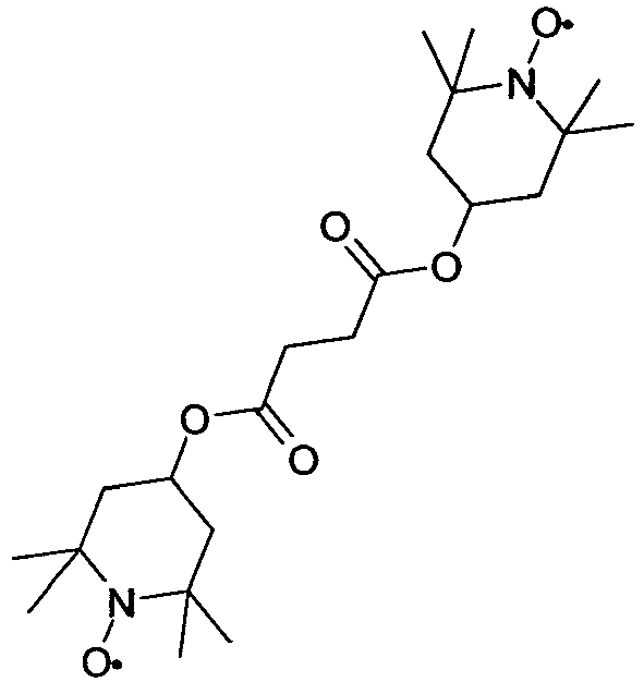
-


-
APUQU-3-F 1,50 % CC-3-V 35,50 % CCP-30CF3 4,00 % CCP-V-1 12,00 % CCP-V2-1 4,50 % CCVC-3-V 4,00 % CPGP-5-2 5,00 % CPGP-5-3 5,00 % DGUQU-4-F 3,00 % PGP-2-3 4,00 % PGP-2-4 2,00 % PGUQU-3-F 5,00 % PGUQU-4-F 3,50 % PGUQU-5-F 3,00 % PPGU-3-F 0,50 % PUQU-3-F 5,00 % PP-1-2V1 2,50 % Klärpunkt [°C]: 110 Δn [589 nm, 20°C]: 0,1257 Δε [1 kHz, 20°C]: 6,3 ε∥ [1 kHz, 20°C]: 9,3 ε⊥ [1 kHz, 20°C]: 3,0 γ1 [mPa·s, 20°C]: 104 K1 [pN, 20°C]: 16,1 K3 [pN, 20°C]: 18,7 V0 [20°C, V]: 1,69 -
CY-3-O2 5,00 % CY-3-O4 15,00 % CCY-3-O2 6,00 % CCY-3-O3 6,00 % CPY-2-O2 3,00 % PTP-102 5,00 % PPTUI-3-2 15,00 % PPTUI-3-4 11,00 % PTP-302FF 12,00 % PTP-502FF 12,00 % CPTP-302FF 5,00 % CPTP-502FF 5,00 % Klärpunkt [°C]: 102 Δn [589 nm, 20°C]: 0,2503 Δε [1 kHz, 20°C]: -4,0 ε∥ [1 kHz, 20°C]: 4,3 ε⊥ [1 kHz, 20°C]: 8,3 γ1 [mPa·s, 20°C]: 392 K1 [pN, 20°C]: 19,5 K3 [pN, 20°C]: 24,0 V0 [20°C, V]: 2,57 -
CC-3-V 35,00 % CCP-3-1 7,50 % CCPC-33 2,00 % CCY-3-O2 7,00 % CCY-4-O2 7,50 % CPY-2-O2 8,50 % CPY-3-O2 9,00 % PP-1-2V1 5,50 % PY-3-O2 8,00 % PYP-2-3 5,00 % Y-4O-O4 5,00 % Klärpunkt [°C]: 79,6 Δn [589 nm, 20°C]: 0,1095 Δε [1 kHz, 20°C]: -2,6 ε∥ [1 kHz, 20°C]: 3,5 ε⊥ [1 kHz, 20°C]: 6,1 γ1 [mPa·s, 20°C]: 92 K1 [pN, 20°C]: 14,5 - Die Mischung aus Beispiel 152 wird zusätzlich mit
0,04 % 
0,02 % 
-
CY-3-O4 25,00 % CY-5-O2 9,00 % CCY-3-O2 7,00 % CCY-3-O3 4,50 % CPY-2-O2 10,00 % CPY-3-O2 10,00 % PYP-2-3 14,00 % PYP-2-4 10,00 % CCP-V-1 3,00 % BCH-32 2,00 % PP-1-2V1 3,50 % PGP-2-3 2,00 % Klärpunkt [°C]: 81,2 Δn [589 nm, 20°C]: 0,1531 Δε [1 kHz, 20°C]: -5,0 ε∥ [1 kHz, 20°C]: 4,1 ε⊥ [1 kHz, 20°C]: 9,1 γ1 [mPa·s, 20°C]: 298 K1 [pN, 20°C]: 13,1 K3 [pN, 20°C]: 15,9 V0 [20°C, V]: 1,89 - Die Mischung aus Beispiel 153 wird zusätzlich mit
10 % 
RM-82 -
CC-3-V 29,00 % CCY-3-O1 8,00 % CCY-3-O2 6,00 % CCY-4-O2 2,00 % CLY-3-O2 8,50 % CLY-3-O3 7,50 % CPY-2-O2 10,00 % CPY-3-O2 7,50 % CY-3-O2 6,50 % PY-3-O2 10,00 % Y-4O-O4 5,00 % Klärpunkt [°C]: 80,1 Δn [589 nm, 20°C]: 0,1033 Δε [1 kHz, 20°C]: -4,5 ε∥ [1 kHz, 20°C]: 4,0 ε⊥ [1 kHz, 20°C]: 8,4 γ1 [mPa·s, 20°C]: 98 K1 [pN, 20°C]: 13,2 K3 [pN, 20°C]: 14,6 V0 [20°C, V]: 1,91 - Die Mischung aus Beispiel 154 wird zusätzlich mit
0,04 % 
0,02 % 
-
CC-3-V 34,00 % CCPC-33 1,00 % CCY-3-1 4,00 % CCY-3-O2 10,00 % CCY-4-O2 9,50 % CPY-2-O2 9,00 % CPY-3-O2 10,00 % PP-1-2V1 1,50 % PY-3-O2 10,00 % PYP-2-3 6,00 % Y-4O-O4 5,00 % Klärpunkt [°C]: 79,7 Δn [589 nm, 20°C]: 0,1095 Δε [1 kHz, 20°C]: -3,5 ε∥ [1 kHz, 20°C]: 3,7 ε⊥ [1 kHz, 20°C]: 7,2 γ1 [mPa·s, 20°C]: 105 K1 [pN, 20°C]: 14,0 - Die Mischung aus Beispiel 155 wird zusätzlich mit
0,04 % 
0,02 % 
-
CC-3-V 19,00 % CCH-3-O1 5,00 % CCY-3-O2 7,00 % CCY-3-O3 12,00 % CCY-4-O2 8,00 % CPY-2-O2 9,50 % CPY-3-O2 10,00 % CY-3-O2 12,00 % CY-3-O4 3,50 % PP-1-3 7,00 % PP-1-4 7,00 % Klärpunkt [°C]: 80,2 Δn [589 nm, 20°C]: 0,1104 Δε [1 kHz, 20°C]: -3,7 ε∥ [1 kHz, 20°C]: 3,6 ε⊥ [1 kHz, 20°C]: 7,3 γ1 [mPa·s, 20°C]: 143 K1 [pN, 20°C]: 12,9 K3 [pN, 20°C]: 14,5 V0 [20°C, V]: 2,09 -
CY-3-O2 15,00 % CY-5-O2 9,50 % CCH-3-O1 4,00 % CCY-3-O2 6,00 % CCY-3-O3 4,50 % CCY-4-O2 6,00 % CCY-5-O2 4,00 % CPY-2-O2 8,00 % CPY-3-O2 9,00 % PYP-2-4 2,00 % CC-3-V 32,00 % Klärpunkt [°C]: 79,1 Δn [589 nm, 20°C]: 0,0944 Δε [1 kHz, 20°C]: -4,0 ε∥ [1 kHz, 20°C]: 3,7 ε⊥ [1 kHz, 20°C]: 7,7 γ1 [mPa·s, 20°C]: 120 K1 [pN, 20°C]: 13,4 K3 [pN, 20°C]: 15,4 V0 [20°C, V]: 2,06 - Die Mischung aus Beispiel 157 wird zusätzlich mit
0,015 % 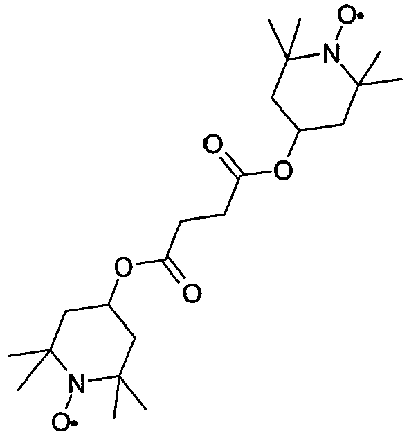
-


- Die Mischung aus Beispiel 158 wird zusätzlich mit
0,015 % 
-


-
CC-3-V 32,50 % CC-3-V1 1,50 % CCH-3-O1 8,50 % CCY-3-O2 5,50 % CLY-3-O2 10,00 % CPY-3-O2 9,50 % PY-3-O2 10,50 % CY-3-O2 14,00 % PYP-2-3 8,00 % Klärpunkt [°C]: 74,7 Δn [589 nm, 20°C]: 0,1090 Δε [1 kHz, 20°C]: -3,8 ε∥ [1 kHz, 20°C]: 3,7 ε⊥ E1 [1 kHz, 20°C]: 7,5 γ1 [mPa·s, 20°C]: 102 K1 [pN, 20°C]: 13,8 K3 [pN, 20°C]: 15,7 V0 [20°C, V]: 2,15 -
CC-3-V 33,00 % CCH-3-O1 6,00 % CCY-3-O2 8,00 % CCY-4-O2 2,50 % CPY-2-O2 8,00 % CPY-3-O2 12,00 % CLY-3-O2 8,00 % PY-1-O4 1,50 % PY-3-02 10,00 % PY-4-O2 8,00 % CY-3-O2 3,00 % Klärpunkt [°C]: 80,2 Δn [589 nm, 20°C]: 0,1116 Δε [1 kHz, 20°C]: -4,1 ε∥ [1 kHz, 20°C]: 3,7 ε⊥ [1 kHz, 20°C]: 7,8 γ1 [mPa·s, 20°C]: 119 K1 [pN, 20°C]: 14,5 K3 [pN, 20°C]: 16,1 V0 [20°C, V]: 2,09 - Die Mischung aus Beispiel 161 wird zusätzlich mit
0,008 % 
-
BCH-3F.F 5,00 % BCH-3F.F.F 8,50 % CC-3-V1 10,00 % CC-4-V 12,50 % CCG-V-F 9,00 % CCP-2F.F.F 3,50 % CCP-3-1 4,50 % CCP-3F.F.F 10,00 % CCP-V-1 12,00 % CCP-V2-1 7,00 % ECCP-5F.F 13,00 % PUQU-3-F 5,00 % Klärpunkt [°C]: 101 Δn [589 nm, 20°C]: 0,0925 Δε [1 kHz, 20°C]: 5,3 ε∥ [1 kHz, 20°C]: 8,3 γ1 [mPa·s, 20°C]: 119 K1 [pN, 20°C]: 14,2 K3 [pN, 20°C]: 19,9 V0 [20°C, V]: 1,73 -


- Die Mischung aus Beispiel 163 wird zusätzlich mit 0,25 % RM-41

-


-
Y-4O-O4 11,50 % CCH-3-O1 4,00 % CCY-3-O2 5,00% CCY-3-O3 2,50 % CPY-3-O2 4,00 % CC-4-V 10,00 % CCP-V-1 6,00 % CCP-V2-1 12,00 % BCH-32 5,00 % PTP-302FF 12,00 % PTP-502FF 12,00 % CPTP-302FF 8,00 % CPTP-502FF 8,00 % Klärpunkt [°C]: 95 Δn [589 nm, 20°C]: 0,1697 Δε [1 kHz, 20°C]: -4,4 ε∥ [1 kHz, 20°C]: 4,1 ε⊥ [1 kHz, 20°C]: 8,5 γ1 [mPa·s, 20°C]: 193 K1 [pN, 20°C]: 16,8 K3 [pN, 20°C]: 19,5 V0 [20°C, V]: 2,23 -


-
PCH-3N.F.F 7,00 % CP-1V-N 18,00 % CP-V2-N 16,00 % CC-4-V 12,00 % CCP-V-1 9,00 % PPTUI-3-2 18,00 % PPTUI-3-4 20,00 % Klärpunkt [°C]: 91 Δn [589 nm, 20°C]: 0,2003 Δε [1 kHz, 20°C]: 10,3 ε∥ [1 kHz, 20°C]: 14,3 ε⊥ [1 kHz, 20°C]: 4,0 -
BCH-32 8,00 % CC-3-V 24,50 % CCP-V-1 8,00 % CCY-2-1 2,00 % CCH-3-O1 6,00 % CCY-3-O3 2,00 % CLY-3-O2 5,00 % CLY-3-O3 5,00 % CPY-2-O2 6,50 % CPY-3-O2 6,00 % CY-3-O2 6,00 % CY-3-O4 3,00 % CY-5-O2 5,00 % PYP-2-3 6,50 % PYP-2-4 6,50 % Klärpunkt [°C]: 96 Δn [589 nm, 20°C]: 0,1195 Δε [1 kHz, 20°C]: -2,7 ε∥ [1 kHz, 20°C]: 3,3 - Die Mischung aus Beispiel 168 wird zusätzlich mit
0,03 % 
0,4 % 
RM-41


Claims (15)
- Abfüllvorrichtung (1) zur Abfüllung eines Fluids in mindestens einen Behälter mit einem Wägesystem (2), mit einem Füllnadelsystem (3), mit einem Aufnahmetisch (7) und mit einer Verstelleinheit (8), dadurch gekennzeichnet dass das Wägesystem (2) mindestens eine an einen Behälterdurchmesser anpassbare Positioniervorrichtung (4) für Behälter aufweist, wobei das Wägesystem (2) auf dem mit einer Lineareinheit (6) vertikal verfahrbaren Aufnahmetisch (7) angeordnet ist und wobei das Füllnadelsystem (3) an der Verstelleinheit (8) in einer in axialer Richtung beabstandeten Position oberhalb der Positioniervorrichtung (4) angeordnet ist.
- Abfüllvorrichtung (1) nach Anspruch 1, dadurch gekennzeichnet, dass die Abfüllvorrichtung (1) zwei oder mehr Wägesysteme (2) umfasst, wobei die Wägesysteme (2) jeweils auf einem mit jeweils einer Lineareinheit (6) vertikal verfahrbaren Aufnahmetisch (7) angeordnet sind.
- Abfüllvorrichtung (1) nach Anspruch 1 oder 2, dadurch gekennzeichnet, dass das Füllnadelsystem (3) eine kombinierte Füll- und Inertisierungsnadel (12) umfasst.
- Abfüllvorrichtung (1) nach einem oder mehreren der Ansprüche 1 bis 3, dadurch gekennzeichnet, dass das Füllnadelsystem (3) in einem aus der Verstelleinheit (8) entnehmbaren Klemmblock (13) angeordnet ist.
- Abfüllvorrichtung (1) nach einem oder mehreren der Ansprüche 1 bis 4, dadurch gekennzeichnet, dass Komponenten des Füllnadelsystems (3), die während des Befüllungsvorgangs mit dem jeweils verwendeten Fluid in Kontakt kommen können, aus Edelstahl und/oder Polytetrafluorethylen (PTFE) bestehen.
- Abfüllvorrichtung (1) nach einem oder mehreren der Ansprüche 1 bis 5, dadurch gekennzeichnet, dass dem Füllnadelsystem (3) ein Membranventil vorgeschaltet ist.
- Abfüllvorrichtung (1) nach einem oder mehreren der Ansprüche 1 bis 6, dadurch gekennzeichnet, dass dem Membranventil eine Filtereinheit (9) zur Filtration der abzufüllenden Flüssigkeit vorgeschaltet ist.
- Abfüllvorrichtung (1) nach einem oder mehreren der Ansprüche 1 bis 7, dadurch gekennzeichnet, dass Ionisatoren seitlich, oberhalb und/oder unterhalb des Füllnadelsystems (3) verbaut sind und diese mit einem gerichteten Luftstrom ionisierter Luft anströmen.
- Abfüllvorrichtung (1) nach einem oder mehreren der Ansprüche 1 bis 8, dadurch gekennzeichnet, dass seitlich zum Füllnadelsystem (3) Schutzwände (16) mit einer antistatischen Beschichtung angeordnet sind.
- Abfüllvorrichtung (1) nach einem oder mehreren der Ansprüche 1 bis 9, dadurch gekennzeichnet, dass die Positioniervorrichtung (4) ringförmig ausgestaltet ist.
- Abfüllvorrichtung (1) nach einem oder mehreren der Ansprüche 1 bis 10, dadurch gekennzeichnet, dass die Vorrichtung ein Tropfenfängersystem (5) aufweist, wobei das an einem Schwenkarm befestigte und ein Gefäß umfassende Tropfenfängersystem (5) unter das Füllnadelsystem (3) schwenkbar ist, falls sich kein Behälter in der Positioniervorrichtung (4) befindet oder der Befüllungsvorgang beendet ist.
- Abfüllvorrichtung (1) nach einem oder mehreren der Ansprüche 1 bis 11 zur Abfüllung einer Flüssigkristallmischung.
- Verwendung einer Abfüllvorrichtung (1) nach einem oder mehreren der Ansprüche 1 bis 12 zur Abfüllung eines Fluids in mindestens einen Behälter.
- Verwendung einer Abfüllvorrichtung (1) nach Anspruch 13 zur Abfüllung einer Flüssigkristallmischung.
- Verwendung einer Abfüllvorrichtung (1) nach Anspruch 13 oder 14, wobei die Abfüllung in einem Reinraum erfolgt.
Applications Claiming Priority (2)
| Application Number | Priority Date | Filing Date | Title |
|---|---|---|---|
| DE102013020638.3A DE102013020638A1 (de) | 2013-12-16 | 2013-12-16 | Abfüllvorrichtung und deren Verwendung zur Abfüllung eines Fluids |
| PCT/EP2014/003258 WO2015090524A1 (de) | 2013-12-16 | 2014-12-05 | Abfüllvorrichtung und deren verwendung zur abfüllung eines fluids |
Publications (2)
| Publication Number | Publication Date |
|---|---|
| EP3083408A1 EP3083408A1 (de) | 2016-10-26 |
| EP3083408B1 true EP3083408B1 (de) | 2018-02-21 |
Family
ID=52103105
Family Applications (1)
| Application Number | Title | Priority Date | Filing Date |
|---|---|---|---|
| EP14812712.9A Active EP3083408B1 (de) | 2013-12-16 | 2014-12-05 | Abfüllvorrichtung und deren verwendung zur abfüllung eines fluids |
Country Status (8)
| Country | Link |
|---|---|
| US (1) | US9944416B2 (de) |
| EP (1) | EP3083408B1 (de) |
| JP (2) | JP2017501089A (de) |
| KR (1) | KR20160098421A (de) |
| CN (1) | CN105813942B (de) |
| DE (1) | DE102013020638A1 (de) |
| TW (1) | TWI651242B (de) |
| WO (1) | WO2015090524A1 (de) |
Families Citing this family (6)
| Publication number | Priority date | Publication date | Assignee | Title |
|---|---|---|---|---|
| EP2286721B1 (de) | 2005-03-01 | 2018-10-24 | Masimo Laboratories, Inc. | Konfidenzmessung physiologischer Parameter |
| KR20160149194A (ko) * | 2014-04-25 | 2016-12-27 | 제이엔씨 주식회사 | 액정 조성물 및 액정 표시 소자 |
| US10846975B2 (en) * | 2015-03-23 | 2020-11-24 | Fountain Master, Llc | Fluid filling station |
| CN116605447A (zh) | 2018-04-27 | 2023-08-18 | 千禧制药公司 | 用于填充容器的系统和方法 |
| CN109567150A (zh) * | 2018-12-12 | 2019-04-05 | 宣城市宣华食品有限公司 | 一种粉条的收集和除水装置 |
| CN115676011B (zh) * | 2021-07-30 | 2025-06-03 | 北京新龙立自动化技术有限公司 | 一种理袋机机架结构 |
Family Cites Families (37)
| Publication number | Priority date | Publication date | Assignee | Title |
|---|---|---|---|---|
| BE795849A (fr) | 1972-02-26 | 1973-08-23 | Merck Patent Gmbh | Phases nematiques modifiees |
| US3814700A (en) | 1972-08-03 | 1974-06-04 | Ibm | Method for controllably varying the electrical properties of nematic liquids and dopants therefor |
| DE2450088A1 (de) | 1974-10-22 | 1976-04-29 | Merck Patent Gmbh | Biphenylester |
| DE2637430A1 (de) | 1976-08-20 | 1978-02-23 | Merck Patent Gmbh | Fluessigkristallines dielektrikum |
| US4211263A (en) | 1978-10-16 | 1980-07-08 | Velasco Scale Company | Dual fill rate liquid filler apparatus having a single control valve |
| DE2853728A1 (de) | 1978-12-13 | 1980-07-17 | Merck Patent Gmbh | Fluessigkristalline carbonsaeureester, verfahren zu ihrer herstellung, diese enthaltende dielektrika und elektrooptisches anzeigeelement |
| DE3661525D1 (en) * | 1985-07-19 | 1989-02-02 | Mitsubishi Heavy Ind Ltd | Equipment for handling various containers |
| JPH0798521B2 (ja) * | 1986-08-20 | 1995-10-25 | 澁谷工業株式会社 | 回転式重量充填装置 |
| EP0261712A1 (de) | 1986-09-04 | 1988-03-30 | Koninklijke Philips Electronics N.V. | Bildanzeigezelle, Verfahren zur Herstellung einer orientierenden Schicht über ein Substrat dieser Bildanzeigezelle und Monomer-Verbindung für ihre Anwendung als orientierende Schicht |
| JPH0688627B2 (ja) * | 1989-03-27 | 1994-11-09 | 日立造船産業株式会社 | 液体充填装置 |
| DE69325555D1 (de) | 1992-04-27 | 1999-08-12 | Merck Patent Gmbh | Elektrooptisches fluessigkristallsystem |
| US5518652A (en) | 1993-07-05 | 1996-05-21 | Merck Patent Gesellschaft Mit Beschrankter Haftung | Liquid crystalline copolymer |
| DE4405316A1 (de) | 1994-02-19 | 1995-08-24 | Basf Ag | Neue polymerisierbare flüssigkristalline Verbindungen |
| DE19504224A1 (de) | 1994-02-23 | 1995-08-24 | Merck Patent Gmbh | Flüssigkristallines Material |
| JP3375777B2 (ja) * | 1994-09-16 | 2003-02-10 | 靜甲株式会社 | 液体充填方法 |
| GB2299333B (en) | 1995-03-29 | 1998-11-25 | Merck Patent Gmbh | Reactive terphenyls |
| DE19532408A1 (de) | 1995-09-01 | 1997-03-06 | Basf Ag | Polymerisierbare flüssigkristalline Verbindungen |
| GB2306470B (en) | 1995-10-05 | 1999-11-03 | Merck Patent Gmbh | Reactive liquid crystalline compound |
| JPH11271329A (ja) * | 1998-03-25 | 1999-10-08 | Hitachi Ltd | 自動分析装置 |
| US6514578B1 (en) | 1999-06-30 | 2003-02-04 | Merck Patent Gesellschaft Mit Beschrankter Haftung | Polymerizable mesogenic tolanes |
| JP2002037203A (ja) * | 2000-07-26 | 2002-02-06 | Nakakin:Kk | 容器への液充填方法 |
| FR2820110B1 (fr) | 2001-01-29 | 2003-08-15 | Valois Sa | Ensemble et procede de fabrication, de montage et de remplissage d'un dispositif de distribution de produit fluide |
| JP2002326607A (ja) * | 2001-04-26 | 2002-11-12 | Matsushita Electric Works Ltd | シリンジへの液状樹脂の充填装置及び充填方法 |
| JP4040904B2 (ja) * | 2002-05-14 | 2008-01-30 | 出光興産株式会社 | 粉粒体充填方法 |
| EP1378557B1 (de) | 2002-07-06 | 2007-02-21 | MERCK PATENT GmbH | Flüssigkristallines Medium |
| ITBO20020523A1 (it) * | 2002-08-05 | 2004-02-06 | Azionaria Costruzioni Acma Spa | Macchina per il riempimento di contenitori. |
| DE102004053474B4 (de) * | 2003-11-21 | 2014-02-06 | Merck Patent Gmbh | Verfahren und System zum Abfüllen, Transportieren, Aufbewahren und Entnehmen von Flüssigkristallen |
| US7438019B2 (en) | 2004-11-29 | 2008-10-21 | Compact Automation Products, Llc | Integrated pneumatic actuator and pump for dispensing controlled amounts of a fluid |
| FR2900127B1 (fr) * | 2006-04-24 | 2008-06-13 | Pack Realisations Sa | Remplisseuse d'emballage a dispositif de centrage et capteur s |
| FR2903975B1 (fr) | 2006-07-21 | 2011-01-21 | Airlessystems | Dispositif et procede de remplissage de reservoir en produit fluide. |
| JP5046975B2 (ja) * | 2008-01-29 | 2012-10-10 | 株式会社クボタ | 液体充填装置 |
| DE102008017942B4 (de) * | 2008-04-09 | 2010-07-29 | Haver & Boecker Ohg | Anlage zum Füllen von Ventilsäcken sowie Verfahren zum Füllen von Ventilsäcken und Anlage zum Abfüllen von Flüssigkeiten in Behältnisse |
| EP2426468B1 (de) * | 2010-09-02 | 2018-05-23 | Mettler-Toledo GmbH | Verfahren zur Bereitstellung von Proben |
| CN102126693B (zh) * | 2010-12-28 | 2012-08-01 | 鼎正动物药业(天津)有限公司 | 导电液体自动灌瓶装置 |
| CN102757003A (zh) * | 2012-06-21 | 2012-10-31 | 常州金海棠茶果专业合作社 | 灌装机的灌装装置 |
| CN203079662U (zh) * | 2013-02-01 | 2013-07-24 | 长春德联化工有限公司 | 一种液体灌装机 |
| CN203280948U (zh) * | 2013-04-28 | 2013-11-13 | 台州市路桥松正自动化设备厂 | 高精度干粉自动灌装设备之粗灌设备 |
-
2013
- 2013-12-16 DE DE102013020638.3A patent/DE102013020638A1/de not_active Withdrawn
-
2014
- 2014-12-05 US US14/761,165 patent/US9944416B2/en not_active Expired - Fee Related
- 2014-12-05 JP JP2016539994A patent/JP2017501089A/ja active Pending
- 2014-12-05 WO PCT/EP2014/003258 patent/WO2015090524A1/de not_active Ceased
- 2014-12-05 CN CN201480068155.7A patent/CN105813942B/zh active Active
- 2014-12-05 KR KR1020167018948A patent/KR20160098421A/ko not_active Ceased
- 2014-12-05 EP EP14812712.9A patent/EP3083408B1/de active Active
- 2014-12-15 TW TW103143725A patent/TWI651242B/zh active
-
2019
- 2019-12-26 JP JP2019004941U patent/JP3225513U/ja not_active Expired - Fee Related
Also Published As
| Publication number | Publication date |
|---|---|
| DE102013020638A1 (de) | 2015-06-18 |
| CN105813942B (zh) | 2019-04-23 |
| JP2017501089A (ja) | 2017-01-12 |
| TWI651242B (zh) | 2019-02-21 |
| WO2015090524A1 (de) | 2015-06-25 |
| US9944416B2 (en) | 2018-04-17 |
| EP3083408A1 (de) | 2016-10-26 |
| KR20160098421A (ko) | 2016-08-18 |
| US20160272346A1 (en) | 2016-09-22 |
| TW201536634A (zh) | 2015-10-01 |
| JP3225513U (ja) | 2020-03-12 |
| CN105813942A (zh) | 2016-07-27 |
Similar Documents
| Publication | Publication Date | Title |
|---|---|---|
| EP3083883B1 (de) | Verfahren zum reinigen einer flüssigkristallmischung | |
| EP2033707B1 (de) | Verfahren zur Herstellung einer homogenen flüssigen Mischung | |
| EP2881383B1 (de) | Mischvorrichtung und deren Verwendung | |
| EP3083408A1 (de) | Abfüllvorrichtung und deren verwendung zur abfüllung eines fluids | |
| EP2957618B1 (de) | Flüssigkristallines medium | |
| EP2652087B1 (de) | Flüssigkristallines medium | |
| EP3119854B1 (de) | Flüssigkristallines medium | |
| DE102013020400A1 (de) | Reinigungsvorrichtung | |
| EP1431369B1 (de) | Flüssigkristallines Medium | |
| EP2886627B1 (de) | Flüssigkristallines Medium | |
| EP2677018B1 (de) | Flüssigkristallines medium | |
| EP2542647B1 (de) | Flüssigkristallines medium | |
| EP1956069B1 (de) | Flüssigkristallines Medium | |
| EP2837671B1 (de) | Flüssigkristallines Medium | |
| EP2993216B1 (de) | Verbindungen und flüssigkristallines medium | |
| EP3663378A1 (de) | Flüssigkristallines medium | |
| WO2011098224A1 (de) | Flüssigkristallines medium |
Legal Events
| Date | Code | Title | Description |
|---|---|---|---|
| PUAI | Public reference made under article 153(3) epc to a published international application that has entered the european phase |
Free format text: ORIGINAL CODE: 0009012 |
|
| 17P | Request for examination filed |
Effective date: 20160415 |
|
| AK | Designated contracting states |
Kind code of ref document: A1 Designated state(s): AL AT BE BG CH CY CZ DE DK EE ES FI FR GB GR HR HU IE IS IT LI LT LU LV MC MK MT NL NO PL PT RO RS SE SI SK SM TR |
|
| AX | Request for extension of the european patent |
Extension state: BA ME |
|
| DAX | Request for extension of the european patent (deleted) | ||
| RIC1 | Information provided on ipc code assigned before grant |
Ipc: B65B 31/00 20060101ALI20170728BHEP Ipc: B65B 3/28 20060101AFI20170728BHEP Ipc: B65B 57/04 20060101ALI20170728BHEP Ipc: B65B 43/59 20060101ALI20170728BHEP Ipc: B65B 65/06 20060101ALI20170728BHEP Ipc: B65B 57/14 20060101ALI20170728BHEP Ipc: B65B 39/12 20060101ALI20170728BHEP |
|
| GRAP | Despatch of communication of intention to grant a patent |
Free format text: ORIGINAL CODE: EPIDOSNIGR1 |
|
| INTG | Intention to grant announced |
Effective date: 20170914 |
|
| GRAS | Grant fee paid |
Free format text: ORIGINAL CODE: EPIDOSNIGR3 |
|
| GRAA | (expected) grant |
Free format text: ORIGINAL CODE: 0009210 |
|
| AK | Designated contracting states |
Kind code of ref document: B1 Designated state(s): AL AT BE BG CH CY CZ DE DK EE ES FI FR GB GR HR HU IE IS IT LI LT LU LV MC MK MT NL NO PL PT RO RS SE SI SK SM TR |
|
| REG | Reference to a national code |
Ref country code: GB Ref legal event code: FG4D Free format text: NOT ENGLISH |
|
| REG | Reference to a national code |
Ref country code: CH Ref legal event code: EP |
|
| REG | Reference to a national code |
Ref country code: AT Ref legal event code: REF Ref document number: 971430 Country of ref document: AT Kind code of ref document: T Effective date: 20180315 |
|
| REG | Reference to a national code |
Ref country code: IE Ref legal event code: FG4D Free format text: LANGUAGE OF EP DOCUMENT: GERMAN |
|
| REG | Reference to a national code |
Ref country code: DE Ref legal event code: R096 Ref document number: 502014007379 Country of ref document: DE |
|
| REG | Reference to a national code |
Ref country code: NL Ref legal event code: MP Effective date: 20180221 |
|
| REG | Reference to a national code |
Ref country code: LT Ref legal event code: MG4D |
|
| PG25 | Lapsed in a contracting state [announced via postgrant information from national office to epo] |
Ref country code: ES Free format text: LAPSE BECAUSE OF FAILURE TO SUBMIT A TRANSLATION OF THE DESCRIPTION OR TO PAY THE FEE WITHIN THE PRESCRIBED TIME-LIMIT Effective date: 20180221 Ref country code: FI Free format text: LAPSE BECAUSE OF FAILURE TO SUBMIT A TRANSLATION OF THE DESCRIPTION OR TO PAY THE FEE WITHIN THE PRESCRIBED TIME-LIMIT Effective date: 20180221 Ref country code: NO Free format text: LAPSE BECAUSE OF FAILURE TO SUBMIT A TRANSLATION OF THE DESCRIPTION OR TO PAY THE FEE WITHIN THE PRESCRIBED TIME-LIMIT Effective date: 20180521 Ref country code: CY Free format text: LAPSE BECAUSE OF FAILURE TO SUBMIT A TRANSLATION OF THE DESCRIPTION OR TO PAY THE FEE WITHIN THE PRESCRIBED TIME-LIMIT Effective date: 20180221 Ref country code: LT Free format text: LAPSE BECAUSE OF FAILURE TO SUBMIT A TRANSLATION OF THE DESCRIPTION OR TO PAY THE FEE WITHIN THE PRESCRIBED TIME-LIMIT Effective date: 20180221 Ref country code: HR Free format text: LAPSE BECAUSE OF FAILURE TO SUBMIT A TRANSLATION OF THE DESCRIPTION OR TO PAY THE FEE WITHIN THE PRESCRIBED TIME-LIMIT Effective date: 20180221 Ref country code: NL Free format text: LAPSE BECAUSE OF FAILURE TO SUBMIT A TRANSLATION OF THE DESCRIPTION OR TO PAY THE FEE WITHIN THE PRESCRIBED TIME-LIMIT Effective date: 20180221 |
|
| PG25 | Lapsed in a contracting state [announced via postgrant information from national office to epo] |
Ref country code: BG Free format text: LAPSE BECAUSE OF FAILURE TO SUBMIT A TRANSLATION OF THE DESCRIPTION OR TO PAY THE FEE WITHIN THE PRESCRIBED TIME-LIMIT Effective date: 20180521 Ref country code: GR Free format text: LAPSE BECAUSE OF FAILURE TO SUBMIT A TRANSLATION OF THE DESCRIPTION OR TO PAY THE FEE WITHIN THE PRESCRIBED TIME-LIMIT Effective date: 20180522 Ref country code: SE Free format text: LAPSE BECAUSE OF FAILURE TO SUBMIT A TRANSLATION OF THE DESCRIPTION OR TO PAY THE FEE WITHIN THE PRESCRIBED TIME-LIMIT Effective date: 20180221 Ref country code: LV Free format text: LAPSE BECAUSE OF FAILURE TO SUBMIT A TRANSLATION OF THE DESCRIPTION OR TO PAY THE FEE WITHIN THE PRESCRIBED TIME-LIMIT Effective date: 20180221 Ref country code: RS Free format text: LAPSE BECAUSE OF FAILURE TO SUBMIT A TRANSLATION OF THE DESCRIPTION OR TO PAY THE FEE WITHIN THE PRESCRIBED TIME-LIMIT Effective date: 20180221 |
|
| PG25 | Lapsed in a contracting state [announced via postgrant information from national office to epo] |
Ref country code: MT Free format text: LAPSE BECAUSE OF FAILURE TO SUBMIT A TRANSLATION OF THE DESCRIPTION OR TO PAY THE FEE WITHIN THE PRESCRIBED TIME-LIMIT Effective date: 20180221 |
|
| PG25 | Lapsed in a contracting state [announced via postgrant information from national office to epo] |
Ref country code: RO Free format text: LAPSE BECAUSE OF FAILURE TO SUBMIT A TRANSLATION OF THE DESCRIPTION OR TO PAY THE FEE WITHIN THE PRESCRIBED TIME-LIMIT Effective date: 20180221 Ref country code: EE Free format text: LAPSE BECAUSE OF FAILURE TO SUBMIT A TRANSLATION OF THE DESCRIPTION OR TO PAY THE FEE WITHIN THE PRESCRIBED TIME-LIMIT Effective date: 20180221 Ref country code: IT Free format text: LAPSE BECAUSE OF FAILURE TO SUBMIT A TRANSLATION OF THE DESCRIPTION OR TO PAY THE FEE WITHIN THE PRESCRIBED TIME-LIMIT Effective date: 20180221 Ref country code: AL Free format text: LAPSE BECAUSE OF FAILURE TO SUBMIT A TRANSLATION OF THE DESCRIPTION OR TO PAY THE FEE WITHIN THE PRESCRIBED TIME-LIMIT Effective date: 20180221 Ref country code: PL Free format text: LAPSE BECAUSE OF FAILURE TO SUBMIT A TRANSLATION OF THE DESCRIPTION OR TO PAY THE FEE WITHIN THE PRESCRIBED TIME-LIMIT Effective date: 20180221 |
|
| REG | Reference to a national code |
Ref country code: DE Ref legal event code: R097 Ref document number: 502014007379 Country of ref document: DE |
|
| PG25 | Lapsed in a contracting state [announced via postgrant information from national office to epo] |
Ref country code: SK Free format text: LAPSE BECAUSE OF FAILURE TO SUBMIT A TRANSLATION OF THE DESCRIPTION OR TO PAY THE FEE WITHIN THE PRESCRIBED TIME-LIMIT Effective date: 20180221 Ref country code: CZ Free format text: LAPSE BECAUSE OF FAILURE TO SUBMIT A TRANSLATION OF THE DESCRIPTION OR TO PAY THE FEE WITHIN THE PRESCRIBED TIME-LIMIT Effective date: 20180221 Ref country code: DK Free format text: LAPSE BECAUSE OF FAILURE TO SUBMIT A TRANSLATION OF THE DESCRIPTION OR TO PAY THE FEE WITHIN THE PRESCRIBED TIME-LIMIT Effective date: 20180221 Ref country code: SM Free format text: LAPSE BECAUSE OF FAILURE TO SUBMIT A TRANSLATION OF THE DESCRIPTION OR TO PAY THE FEE WITHIN THE PRESCRIBED TIME-LIMIT Effective date: 20180221 |
|
| PLBE | No opposition filed within time limit |
Free format text: ORIGINAL CODE: 0009261 |
|
| STAA | Information on the status of an ep patent application or granted ep patent |
Free format text: STATUS: NO OPPOSITION FILED WITHIN TIME LIMIT |
|
| 26N | No opposition filed |
Effective date: 20181122 |
|
| PG25 | Lapsed in a contracting state [announced via postgrant information from national office to epo] |
Ref country code: SI Free format text: LAPSE BECAUSE OF FAILURE TO SUBMIT A TRANSLATION OF THE DESCRIPTION OR TO PAY THE FEE WITHIN THE PRESCRIBED TIME-LIMIT Effective date: 20180221 |
|
| REG | Reference to a national code |
Ref country code: CH Ref legal event code: PL |
|
| GBPC | Gb: european patent ceased through non-payment of renewal fee |
Effective date: 20181205 |
|
| PG25 | Lapsed in a contracting state [announced via postgrant information from national office to epo] |
Ref country code: LU Free format text: LAPSE BECAUSE OF NON-PAYMENT OF DUE FEES Effective date: 20181205 Ref country code: MC Free format text: LAPSE BECAUSE OF FAILURE TO SUBMIT A TRANSLATION OF THE DESCRIPTION OR TO PAY THE FEE WITHIN THE PRESCRIBED TIME-LIMIT Effective date: 20180221 |
|
| REG | Reference to a national code |
Ref country code: IE Ref legal event code: MM4A |
|
| REG | Reference to a national code |
Ref country code: BE Ref legal event code: MM Effective date: 20181231 |
|
| PG25 | Lapsed in a contracting state [announced via postgrant information from national office to epo] |
Ref country code: IE Free format text: LAPSE BECAUSE OF NON-PAYMENT OF DUE FEES Effective date: 20181205 Ref country code: FR Free format text: LAPSE BECAUSE OF NON-PAYMENT OF DUE FEES Effective date: 20181231 |
|
| PG25 | Lapsed in a contracting state [announced via postgrant information from national office to epo] |
Ref country code: BE Free format text: LAPSE BECAUSE OF NON-PAYMENT OF DUE FEES Effective date: 20181231 |
|
| PG25 | Lapsed in a contracting state [announced via postgrant information from national office to epo] |
Ref country code: GB Free format text: LAPSE BECAUSE OF NON-PAYMENT OF DUE FEES Effective date: 20181205 Ref country code: LI Free format text: LAPSE BECAUSE OF NON-PAYMENT OF DUE FEES Effective date: 20181231 Ref country code: CH Free format text: LAPSE BECAUSE OF NON-PAYMENT OF DUE FEES Effective date: 20181231 |
|
| PG25 | Lapsed in a contracting state [announced via postgrant information from national office to epo] |
Ref country code: TR Free format text: LAPSE BECAUSE OF FAILURE TO SUBMIT A TRANSLATION OF THE DESCRIPTION OR TO PAY THE FEE WITHIN THE PRESCRIBED TIME-LIMIT Effective date: 20180221 |
|
| PG25 | Lapsed in a contracting state [announced via postgrant information from national office to epo] |
Ref country code: PT Free format text: LAPSE BECAUSE OF FAILURE TO SUBMIT A TRANSLATION OF THE DESCRIPTION OR TO PAY THE FEE WITHIN THE PRESCRIBED TIME-LIMIT Effective date: 20180221 |
|
| PG25 | Lapsed in a contracting state [announced via postgrant information from national office to epo] |
Ref country code: MK Free format text: LAPSE BECAUSE OF NON-PAYMENT OF DUE FEES Effective date: 20180221 Ref country code: HU Free format text: LAPSE BECAUSE OF FAILURE TO SUBMIT A TRANSLATION OF THE DESCRIPTION OR TO PAY THE FEE WITHIN THE PRESCRIBED TIME-LIMIT; INVALID AB INITIO Effective date: 20141205 |
|
| PG25 | Lapsed in a contracting state [announced via postgrant information from national office to epo] |
Ref country code: IS Free format text: LAPSE BECAUSE OF FAILURE TO SUBMIT A TRANSLATION OF THE DESCRIPTION OR TO PAY THE FEE WITHIN THE PRESCRIBED TIME-LIMIT Effective date: 20180621 |
|
| REG | Reference to a national code |
Ref country code: AT Ref legal event code: MM01 Ref document number: 971430 Country of ref document: AT Kind code of ref document: T Effective date: 20191205 |
|
| PG25 | Lapsed in a contracting state [announced via postgrant information from national office to epo] |
Ref country code: AT Free format text: LAPSE BECAUSE OF NON-PAYMENT OF DUE FEES Effective date: 20191205 |
|
| P01 | Opt-out of the competence of the unified patent court (upc) registered |
Effective date: 20230518 |
|
| PGFP | Annual fee paid to national office [announced via postgrant information from national office to epo] |
Ref country code: DE Payment date: 20251126 Year of fee payment: 12 |