EP3082620B1 - Resektionslinienführung für einen medizinischen eingriff - Google Patents
Resektionslinienführung für einen medizinischen eingriff Download PDFInfo
- Publication number
- EP3082620B1 EP3082620B1 EP14872137.6A EP14872137A EP3082620B1 EP 3082620 B1 EP3082620 B1 EP 3082620B1 EP 14872137 A EP14872137 A EP 14872137A EP 3082620 B1 EP3082620 B1 EP 3082620B1
- Authority
- EP
- European Patent Office
- Prior art keywords
- resection line
- line guide
- flexible member
- stomach
- clamp
- Prior art date
- Legal status (The legal status is an assumption and is not a legal conclusion. Google has not performed a legal analysis and makes no representation as to the accuracy of the status listed.)
- Active
Links
- 238000002271 resection Methods 0.000 title claims description 510
- 238000000034 method Methods 0.000 title claims description 83
- 230000007246 mechanism Effects 0.000 claims description 185
- 210000003484 anatomy Anatomy 0.000 claims description 66
- 210000002784 stomach Anatomy 0.000 description 263
- 230000033001 locomotion Effects 0.000 description 61
- 210000001519 tissue Anatomy 0.000 description 45
- 238000007682 sleeve gastrectomy Methods 0.000 description 28
- 238000001356 surgical procedure Methods 0.000 description 19
- 210000003811 finger Anatomy 0.000 description 18
- 238000005520 cutting process Methods 0.000 description 17
- 210000000683 abdominal cavity Anatomy 0.000 description 14
- 230000006835 compression Effects 0.000 description 11
- 238000007906 compression Methods 0.000 description 11
- 230000007423 decrease Effects 0.000 description 11
- 230000008569 process Effects 0.000 description 10
- 241000321728 Tritogonia verrucosa Species 0.000 description 9
- 239000011324 bead Substances 0.000 description 8
- 210000003236 esophagogastric junction Anatomy 0.000 description 8
- 238000012800 visualization Methods 0.000 description 8
- 230000002496 gastric effect Effects 0.000 description 6
- 210000002414 leg Anatomy 0.000 description 6
- 230000013011 mating Effects 0.000 description 6
- 208000008589 Obesity Diseases 0.000 description 5
- 235000020824 obesity Nutrition 0.000 description 5
- 230000004580 weight loss Effects 0.000 description 5
- 230000008859 change Effects 0.000 description 4
- 238000004140 cleaning Methods 0.000 description 4
- 230000008878 coupling Effects 0.000 description 4
- 238000010168 coupling process Methods 0.000 description 4
- 238000005859 coupling reaction Methods 0.000 description 4
- 239000000463 material Substances 0.000 description 4
- 230000009471 action Effects 0.000 description 3
- 238000013459 approach Methods 0.000 description 3
- 238000007681 bariatric surgery Methods 0.000 description 3
- 230000008901 benefit Effects 0.000 description 3
- 238000013110 gastrectomy Methods 0.000 description 3
- 238000002357 laparoscopic surgery Methods 0.000 description 3
- 210000004072 lung Anatomy 0.000 description 3
- 229920003023 plastic Polymers 0.000 description 3
- 239000007787 solid Substances 0.000 description 3
- 230000000007 visual effect Effects 0.000 description 3
- 241001272720 Medialuna californiensis Species 0.000 description 2
- 206010033307 Overweight Diseases 0.000 description 2
- 230000003213 activating effect Effects 0.000 description 2
- 230000003542 behavioural effect Effects 0.000 description 2
- 230000009286 beneficial effect Effects 0.000 description 2
- 230000015572 biosynthetic process Effects 0.000 description 2
- 239000003086 colorant Substances 0.000 description 2
- 201000010099 disease Diseases 0.000 description 2
- 208000037265 diseases, disorders, signs and symptoms Diseases 0.000 description 2
- 210000003238 esophagus Anatomy 0.000 description 2
- 238000010304 firing Methods 0.000 description 2
- 238000003780 insertion Methods 0.000 description 2
- 230000037431 insertion Effects 0.000 description 2
- 210000003734 kidney Anatomy 0.000 description 2
- 210000004185 liver Anatomy 0.000 description 2
- 238000005259 measurement Methods 0.000 description 2
- 239000002184 metal Substances 0.000 description 2
- 238000013059 nephrectomy Methods 0.000 description 2
- 210000000056 organ Anatomy 0.000 description 2
- 239000004033 plastic Substances 0.000 description 2
- 238000003825 pressing Methods 0.000 description 2
- 210000001187 pylorus Anatomy 0.000 description 2
- 238000000926 separation method Methods 0.000 description 2
- 210000003813 thumb Anatomy 0.000 description 2
- 238000012546 transfer Methods 0.000 description 2
- 238000003466 welding Methods 0.000 description 2
- 229920002799 BoPET Polymers 0.000 description 1
- 206010061958 Food Intolerance Diseases 0.000 description 1
- 208000034991 Hiatal Hernia Diseases 0.000 description 1
- 206010020028 Hiatus hernia Diseases 0.000 description 1
- 208000031911 Multiple Chronic Conditions Diseases 0.000 description 1
- 239000005041 Mylar™ Substances 0.000 description 1
- 206010028980 Neoplasm Diseases 0.000 description 1
- 239000002033 PVDF binder Substances 0.000 description 1
- 229920000508 Vectran Polymers 0.000 description 1
- 239000004979 Vectran Substances 0.000 description 1
- 210000001015 abdomen Anatomy 0.000 description 1
- 230000003187 abdominal effect Effects 0.000 description 1
- 210000003815 abdominal wall Anatomy 0.000 description 1
- 230000004913 activation Effects 0.000 description 1
- 239000000853 adhesive Substances 0.000 description 1
- 238000004026 adhesive bonding Methods 0.000 description 1
- 230000001070 adhesive effect Effects 0.000 description 1
- 230000000151 anti-reflux effect Effects 0.000 description 1
- 238000005452 bending Methods 0.000 description 1
- 239000000560 biocompatible material Substances 0.000 description 1
- 230000036770 blood supply Effects 0.000 description 1
- 201000011510 cancer Diseases 0.000 description 1
- 210000002318 cardia Anatomy 0.000 description 1
- 230000007211 cardiovascular event Effects 0.000 description 1
- 238000010586 diagram Methods 0.000 description 1
- 238000011038 discontinuous diafiltration by volume reduction Methods 0.000 description 1
- 238000006073 displacement reaction Methods 0.000 description 1
- 230000000694 effects Effects 0.000 description 1
- 230000007613 environmental effect Effects 0.000 description 1
- 239000000835 fiber Substances 0.000 description 1
- 239000012530 fluid Substances 0.000 description 1
- 210000005224 forefinger Anatomy 0.000 description 1
- 208000021302 gastroesophageal reflux disease Diseases 0.000 description 1
- 230000002068 genetic effect Effects 0.000 description 1
- 238000007683 laparoscopic Roux-en-Y gastric bypass Methods 0.000 description 1
- 238000011866 long-term treatment Methods 0.000 description 1
- 210000000111 lower esophageal sphincter Anatomy 0.000 description 1
- 210000001699 lower leg Anatomy 0.000 description 1
- 238000010197 meta-analysis Methods 0.000 description 1
- 230000001338 necrotic effect Effects 0.000 description 1
- 210000002747 omentum Anatomy 0.000 description 1
- 229920000515 polycarbonate Polymers 0.000 description 1
- 239000004417 polycarbonate Substances 0.000 description 1
- 229920000642 polymer Polymers 0.000 description 1
- 229920002981 polyvinylidene fluoride Polymers 0.000 description 1
- 238000012805 post-processing Methods 0.000 description 1
- 230000002028 premature Effects 0.000 description 1
- 230000002265 prevention Effects 0.000 description 1
- 230000005180 public health Effects 0.000 description 1
- 230000008439 repair process Effects 0.000 description 1
- 230000002441 reversible effect Effects 0.000 description 1
- 238000007789 sealing Methods 0.000 description 1
- 238000009958 sewing Methods 0.000 description 1
- 210000004872 soft tissue Anatomy 0.000 description 1
- 125000006850 spacer group Chemical group 0.000 description 1
- 230000000087 stabilizing effect Effects 0.000 description 1
- 229910001220 stainless steel Inorganic materials 0.000 description 1
- 239000010935 stainless steel Substances 0.000 description 1
- 239000013589 supplement Substances 0.000 description 1
- 230000025366 tissue development Effects 0.000 description 1
- 238000012549 training Methods 0.000 description 1
- 238000013519 translation Methods 0.000 description 1
- 238000011282 treatment Methods 0.000 description 1
- 238000002604 ultrasonography Methods 0.000 description 1
- 230000037220 weight regain Effects 0.000 description 1
Images


Classifications
-
- A—HUMAN NECESSITIES
- A61—MEDICAL OR VETERINARY SCIENCE; HYGIENE
- A61B—DIAGNOSIS; SURGERY; IDENTIFICATION
- A61B17/00—Surgical instruments, devices or methods, e.g. tourniquets
- A61B17/12—Surgical instruments, devices or methods, e.g. tourniquets for ligaturing or otherwise compressing tubular parts of the body, e.g. blood vessels, umbilical cord
- A61B17/122—Clamps or clips, e.g. for the umbilical cord
-
- A—HUMAN NECESSITIES
- A61—MEDICAL OR VETERINARY SCIENCE; HYGIENE
- A61B—DIAGNOSIS; SURGERY; IDENTIFICATION
- A61B17/00—Surgical instruments, devices or methods, e.g. tourniquets
- A61B17/00234—Surgical instruments, devices or methods, e.g. tourniquets for minimally invasive surgery
-
- A—HUMAN NECESSITIES
- A61—MEDICAL OR VETERINARY SCIENCE; HYGIENE
- A61B—DIAGNOSIS; SURGERY; IDENTIFICATION
- A61B17/00—Surgical instruments, devices or methods, e.g. tourniquets
- A61B17/068—Surgical staplers, e.g. containing multiple staples or clamps
-
- A—HUMAN NECESSITIES
- A61—MEDICAL OR VETERINARY SCIENCE; HYGIENE
- A61B—DIAGNOSIS; SURGERY; IDENTIFICATION
- A61B17/00—Surgical instruments, devices or methods, e.g. tourniquets
- A61B17/12—Surgical instruments, devices or methods, e.g. tourniquets for ligaturing or otherwise compressing tubular parts of the body, e.g. blood vessels, umbilical cord
- A61B17/12009—Implements for ligaturing other than by clamps or clips, e.g. using a loop with a slip knot
-
- A—HUMAN NECESSITIES
- A61—MEDICAL OR VETERINARY SCIENCE; HYGIENE
- A61F—FILTERS IMPLANTABLE INTO BLOOD VESSELS; PROSTHESES; DEVICES PROVIDING PATENCY TO, OR PREVENTING COLLAPSING OF, TUBULAR STRUCTURES OF THE BODY, e.g. STENTS; ORTHOPAEDIC, NURSING OR CONTRACEPTIVE DEVICES; FOMENTATION; TREATMENT OR PROTECTION OF EYES OR EARS; BANDAGES, DRESSINGS OR ABSORBENT PADS; FIRST-AID KITS
- A61F5/00—Orthopaedic methods or devices for non-surgical treatment of bones or joints; Nursing devices; Anti-rape devices
- A61F5/0003—Apparatus for the treatment of obesity; Anti-eating devices
- A61F5/0013—Implantable devices or invasive measures
- A61F5/0083—Reducing the size of the stomach, e.g. gastroplasty
-
- A—HUMAN NECESSITIES
- A61—MEDICAL OR VETERINARY SCIENCE; HYGIENE
- A61B—DIAGNOSIS; SURGERY; IDENTIFICATION
- A61B17/00—Surgical instruments, devices or methods, e.g. tourniquets
- A61B17/068—Surgical staplers, e.g. containing multiple staples or clamps
- A61B17/072—Surgical staplers, e.g. containing multiple staples or clamps for applying a row of staples in a single action, e.g. the staples being applied simultaneously
- A61B17/07207—Surgical staplers, e.g. containing multiple staples or clamps for applying a row of staples in a single action, e.g. the staples being applied simultaneously the staples being applied sequentially
-
- A—HUMAN NECESSITIES
- A61—MEDICAL OR VETERINARY SCIENCE; HYGIENE
- A61B—DIAGNOSIS; SURGERY; IDENTIFICATION
- A61B17/00—Surgical instruments, devices or methods, e.g. tourniquets
- A61B17/12—Surgical instruments, devices or methods, e.g. tourniquets for ligaturing or otherwise compressing tubular parts of the body, e.g. blood vessels, umbilical cord
- A61B17/122—Clamps or clips, e.g. for the umbilical cord
- A61B17/1227—Spring clips
-
- A—HUMAN NECESSITIES
- A61—MEDICAL OR VETERINARY SCIENCE; HYGIENE
- A61B—DIAGNOSIS; SURGERY; IDENTIFICATION
- A61B17/00—Surgical instruments, devices or methods, e.g. tourniquets
- A61B2017/00017—Electrical control of surgical instruments
- A61B2017/00022—Sensing or detecting at the treatment site
- A61B2017/00057—Light
- A61B2017/00066—Light intensity
-
- A—HUMAN NECESSITIES
- A61—MEDICAL OR VETERINARY SCIENCE; HYGIENE
- A61B—DIAGNOSIS; SURGERY; IDENTIFICATION
- A61B17/00—Surgical instruments, devices or methods, e.g. tourniquets
- A61B2017/00017—Electrical control of surgical instruments
- A61B2017/00115—Electrical control of surgical instruments with audible or visual output
-
- A—HUMAN NECESSITIES
- A61—MEDICAL OR VETERINARY SCIENCE; HYGIENE
- A61B—DIAGNOSIS; SURGERY; IDENTIFICATION
- A61B17/00—Surgical instruments, devices or methods, e.g. tourniquets
- A61B17/00234—Surgical instruments, devices or methods, e.g. tourniquets for minimally invasive surgery
- A61B2017/00292—Surgical instruments, devices or methods, e.g. tourniquets for minimally invasive surgery mounted on or guided by flexible, e.g. catheter-like, means
- A61B2017/003—Steerable
- A61B2017/00305—Constructional details of the flexible means
- A61B2017/00314—Separate linked members
-
- A—HUMAN NECESSITIES
- A61—MEDICAL OR VETERINARY SCIENCE; HYGIENE
- A61B—DIAGNOSIS; SURGERY; IDENTIFICATION
- A61B17/00—Surgical instruments, devices or methods, e.g. tourniquets
- A61B17/00234—Surgical instruments, devices or methods, e.g. tourniquets for minimally invasive surgery
- A61B2017/00358—Snares for grasping
-
- A—HUMAN NECESSITIES
- A61—MEDICAL OR VETERINARY SCIENCE; HYGIENE
- A61B—DIAGNOSIS; SURGERY; IDENTIFICATION
- A61B17/00—Surgical instruments, devices or methods, e.g. tourniquets
- A61B2017/00367—Details of actuation of instruments, e.g. relations between pushing buttons, or the like, and activation of the tool, working tip, or the like
- A61B2017/00407—Ratchet means
-
- A—HUMAN NECESSITIES
- A61—MEDICAL OR VETERINARY SCIENCE; HYGIENE
- A61B—DIAGNOSIS; SURGERY; IDENTIFICATION
- A61B17/00—Surgical instruments, devices or methods, e.g. tourniquets
- A61B2017/0046—Surgical instruments, devices or methods, e.g. tourniquets with a releasable handle; with handle and operating part separable
-
- A—HUMAN NECESSITIES
- A61—MEDICAL OR VETERINARY SCIENCE; HYGIENE
- A61B—DIAGNOSIS; SURGERY; IDENTIFICATION
- A61B17/00—Surgical instruments, devices or methods, e.g. tourniquets
- A61B2017/00743—Type of operation; Specification of treatment sites
- A61B2017/00818—Treatment of the gastro-intestinal system
-
- A—HUMAN NECESSITIES
- A61—MEDICAL OR VETERINARY SCIENCE; HYGIENE
- A61B—DIAGNOSIS; SURGERY; IDENTIFICATION
- A61B17/00—Surgical instruments, devices or methods, e.g. tourniquets
- A61B2017/00831—Material properties
- A61B2017/00867—Material properties shape memory effect
-
- A—HUMAN NECESSITIES
- A61—MEDICAL OR VETERINARY SCIENCE; HYGIENE
- A61B—DIAGNOSIS; SURGERY; IDENTIFICATION
- A61B17/00—Surgical instruments, devices or methods, e.g. tourniquets
- A61B2017/00831—Material properties
- A61B2017/00876—Material properties magnetic
-
- A—HUMAN NECESSITIES
- A61—MEDICAL OR VETERINARY SCIENCE; HYGIENE
- A61B—DIAGNOSIS; SURGERY; IDENTIFICATION
- A61B17/00—Surgical instruments, devices or methods, e.g. tourniquets
- A61B2017/00831—Material properties
- A61B2017/00902—Material properties transparent or translucent
-
- A—HUMAN NECESSITIES
- A61—MEDICAL OR VETERINARY SCIENCE; HYGIENE
- A61B—DIAGNOSIS; SURGERY; IDENTIFICATION
- A61B17/00—Surgical instruments, devices or methods, e.g. tourniquets
- A61B2017/00982—General structural features
- A61B2017/00991—Telescopic means
-
- A—HUMAN NECESSITIES
- A61—MEDICAL OR VETERINARY SCIENCE; HYGIENE
- A61B—DIAGNOSIS; SURGERY; IDENTIFICATION
- A61B17/00—Surgical instruments, devices or methods, e.g. tourniquets
- A61B17/068—Surgical staplers, e.g. containing multiple staples or clamps
- A61B17/072—Surgical staplers, e.g. containing multiple staples or clamps for applying a row of staples in a single action, e.g. the staples being applied simultaneously
- A61B2017/07214—Stapler heads
- A61B2017/07285—Stapler heads characterised by its cutter
-
- A—HUMAN NECESSITIES
- A61—MEDICAL OR VETERINARY SCIENCE; HYGIENE
- A61B—DIAGNOSIS; SURGERY; IDENTIFICATION
- A61B17/00—Surgical instruments, devices or methods, e.g. tourniquets
- A61B17/28—Surgical forceps
- A61B17/29—Forceps for use in minimally invasive surgery
- A61B2017/2926—Details of heads or jaws
- A61B2017/2927—Details of heads or jaws the angular position of the head being adjustable with respect to the shaft
- A61B2017/2929—Details of heads or jaws the angular position of the head being adjustable with respect to the shaft with a head rotatable about the longitudinal axis of the shaft
-
- A—HUMAN NECESSITIES
- A61—MEDICAL OR VETERINARY SCIENCE; HYGIENE
- A61B—DIAGNOSIS; SURGERY; IDENTIFICATION
- A61B17/00—Surgical instruments, devices or methods, e.g. tourniquets
- A61B17/28—Surgical forceps
- A61B17/29—Forceps for use in minimally invasive surgery
- A61B2017/2946—Locking means
-
- A—HUMAN NECESSITIES
- A61—MEDICAL OR VETERINARY SCIENCE; HYGIENE
- A61B—DIAGNOSIS; SURGERY; IDENTIFICATION
- A61B17/00—Surgical instruments, devices or methods, e.g. tourniquets
- A61B17/32—Surgical cutting instruments
- A61B2017/320052—Guides for cutting instruments
-
- A—HUMAN NECESSITIES
- A61—MEDICAL OR VETERINARY SCIENCE; HYGIENE
- A61B—DIAGNOSIS; SURGERY; IDENTIFICATION
- A61B90/00—Instruments, implements or accessories specially adapted for surgery or diagnosis and not covered by any of the groups A61B1/00 - A61B50/00, e.g. for luxation treatment or for protecting wound edges
- A61B90/06—Measuring instruments not otherwise provided for
- A61B2090/061—Measuring instruments not otherwise provided for for measuring dimensions, e.g. length
-
- A—HUMAN NECESSITIES
- A61—MEDICAL OR VETERINARY SCIENCE; HYGIENE
- A61B—DIAGNOSIS; SURGERY; IDENTIFICATION
- A61B90/00—Instruments, implements or accessories specially adapted for surgery or diagnosis and not covered by any of the groups A61B1/00 - A61B50/00, e.g. for luxation treatment or for protecting wound edges
- A61B90/08—Accessories or related features not otherwise provided for
- A61B2090/0807—Indication means
-
- A—HUMAN NECESSITIES
- A61—MEDICAL OR VETERINARY SCIENCE; HYGIENE
- A61B—DIAGNOSIS; SURGERY; IDENTIFICATION
- A61B5/00—Measuring for diagnostic purposes; Identification of persons
- A61B5/103—Detecting, measuring or recording devices for testing the shape, pattern, colour, size or movement of the body or parts thereof, for diagnostic purposes
- A61B5/107—Measuring physical dimensions, e.g. size of the entire body or parts thereof
- A61B5/1076—Measuring physical dimensions, e.g. size of the entire body or parts thereof for measuring dimensions inside body cavities, e.g. using catheters
Definitions
- the invention relates to medical procedures, and more particularly to apparatuses and methods of using a resection line guide in various medical procedures.
- Obesity as a disease, affects a significant portion of the world's population. Obesity often leads to multiple chronic medical conditions and premature death from cardiovascular events and cancer.
- the U.S. Centers for Disease Control and Prevention (“CDC") reports that over 33% of the U.S. population is obese, with a body mass index (“BMI") of over 30, and another 35-40% of the population is overweight, with a BMI of 25-30.
- BMI body mass index
- the CDC reports that the percent of the population being either overweight or obese by 2018 will be 75%.
- the CDC also reports that obesity directly costs the U.S. economy $147 billion currently, and projects that the costs will approach $315 billion by 2020.
- the increase in obesity and the financial impact on the local economy is not limited to the United States but impacts many countries throughout the world.
- the resultant gastric pouch generally should be about 80 mL to about 820 mL in volume, should not be narrowed at the incisura angularis, should be as straight as possible to avoid obstruction from spiraling or zigzagging, should be about 0.5 cm to about 2 cm away from the gastroesophageal junction, and should be about 2 cm to about 10 cm away from the pylorus.
- a vertical sleeve gastrectomy is typically performed using standard laparoscopic equipment.
- the greater curvature of the stomach is mobilized by using vessel-sealing devices to seal the gastric branches of the gastroepiploic vessels and the short gastric vessels.
- the posterior adhesions of the stomach are also divided so the stomach is fully mobilized while the blood supply to the lesser curvature remains intact.
- the left crus of the diaphragm is an important landmark to ensure the fundus has been fully mobilized.
- a calibration tube or bougie is typically introduced into the stomach through the mouth.
- the bougie is inserted through the mouth, down the esophagus, and into the stomach, where it is used as a point of reference in order to help align the initial staple fire.
- the bougie acts as a left-hand landmark, which the surgeon uses to visualize the path of the staple line.
- a surgeon creating a sleeve gastrectomy staple line will estimate 2.0 cm away from the lesser curvature of the stomach and visually orient the stapler.
- constant diameter bougies cannot be used to facilitate orienting the stapler, only surgeon experience and estimation is used.
- the staple line At the top of the staple line, it is important to not divide part of the esophagus or the ⁇ sling fibers' of the cardia, which participate in the physiologic anti-reflux action of the lower esophageal sphincter. Surgeons must use visual cues to ensure that the staple line is a safe distance away from the gastroesophageal junction.
- Resection is accomplished by a series of applications of a laparoscopic linear surgical stapler.
- the staplers that are most commonly used for sleeve gastrectomy are 60 mm in length and include an integrated cutting blade. Each staple application places three rows of overlapping staples into the tissue on either side of the cutting blade.
- the average number of staple fires per procedure is 4 to 6 in order to create a continuous resection line. This results in a resection line that is approximately 15 cm to about 36 cm on average.
- surgeon training, experience, and trial and error are the only tools used to aid the surgeon in determining the path of the resection line in a vertical sleeve gastrectomy.
- the resection line is important in sleeve gastrectomy because the amount of weight loss and subsequent medical complications may be a direct result of the quality of the resultant anatomy.
- the resultant anatomy is determined by the resection line created by the surgeon during the gastrectomy. Negative consequences related to the quality of the resection line may include, for example, gastroesophageal reflux, weight loss failure, weight regain, food intolerance, resection line bleed, and leak.
- Leaks are the most concerning complication of a vertical sleeve gastrectomy. In large pooled databases, the leak rate is approximately 0.3 to 2%. Leak is thought to be prevented by making a straight resection line that avoids crossing staple cartridge applications, has no narrow segments (particularly at the incisura angularis), is about 1 cm from the gastroesophageal junction, and has a squared-off final application. Generally speaking, leak is not prevented by over-sewing the resection line or using buttress material in the resection line. Leak is thought to be more a result of poor resultant stomach anatomy. Poor anatomy is a direct result of the shortcomings of the calibration equipment and technique used to create the resection line. Conventional calibration tubes specifically designed for use in a sleeve gastrectomy may provide some user benefits, but fail to reliably produce the proper geometry of the resultant anatomy from the vertical sleeve gastrectomy.
- new apparatuses and methods are needed to address the shortcomings of existing apparatuses and methods. More particularly, new apparatuses and methods are needed that improve the consistency and quality of the resection line created during a medical procedure, such as a vertical sleeve gastrectomy.
- a medical device for performing a medical procedure comprising a manipulator including a shaft and a resection line guide,
- the resection line guide comprising a flexible member operably coupled to the manipulator and extending through the shaft to the resection line guide, wherein the manipulator is configured to place the flexible member in tension so that the resection line guide is clampable on an anatomical structure in the human body; a first clamp member for contacting the anatomical structure; and a second clamp member for contacting the anatomical structure generally opposite the anatomical structure to that of the first clamp member.
- the resection line guide is coupled to the shaft and one of the first clamp member and the second clamp member is coupled to the shaft.
- the flexible member extends from the first clamp member to the second clamp member so that the flexible member moves the first clamp member toward the second clamp member to provide a clamping force on the anatomical structure.
- the first clamp member and the second clamp member are coupled together by a hinge joint, which hinge joint is coupled to a distal end of the clamp members and the flexible member is coupled at and between proximal ends of the clamp members.
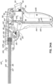
- the resection line guide is coupled to the shaft at a ball-and-socket type joint.
- the resection line guide is coupled to the shaft at a joint.
- the resection line guide the joint is configured to be locked to fix an orientation between the shaft and the resection line guide.
- the joint is in a normally locked configuration.
- the joint is operably coupled to the manipulator, and wherein the manipulator includes a mechanism for selectively unlocking the joint.
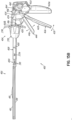
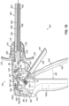
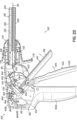
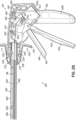
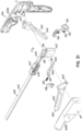
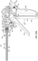
- the manipulator includes a housing and a clamping mechanism operable to selectively tension the flexible member.
- the clamping mechanism includes a knob rotatable so as to withdrawal the flexible member from the resection line guide.
- the knob includes a follower pin and a cam rod, which cam rod has a helical groove along at least a portion of its outer surface which is able to receive the follower pin, the flexible member being secured to the cam rod, and the knob being operably coupled to the cam rod such that rotation of the knob relative to the housing rotates the follower pin which interacts with the groove to forcibly slide the cam rod relative to the housing.
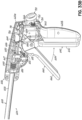
- the manipulator may include a housing, a clamping mechanism operable to selectively apply tension to the flexible member in an engaged position, and a stop and release mechanism for maintaining the clamping mechanism in the engaged position.
- the resection line guide may be configured to provide a first stage clamping force on the anatomical structure, the first stage clamping force configured to couple the resection line guide to the anatomical structure while permitting the clamp members to be moved relative to the anatomical structure.
- the first stage clamping force may be between about 0.5 g/mm2 and about 4 g/mm2.
- the manipulator may further be provided with includes a spring reel for letting out a length of the flexible member and taking up a length of the flexible member that is configured to provide the first stage clamping force.
- embodiments of the present invention are directed to a medical device comprising a manipulator, including a shaft and a resection line guide for directing the application of a resection line during a surgical procedure involving the resection of at least a part of an anatomical structure.
- the resection line guide comprises at least a flexible member operably coupled to the manipulator and extending through the shaft to the resection line guide, wherein the manipulator is configured to place the flexible member in tension so that the resection line guide is clampable on an anatomical structure in the human body; a first clamp member for contacting the anatomical structure; and a second clamp member for contacting the anatomical structure generally opposite the anatomical structure to that of the first clamp member.
- the resection line guide is coupled to the shaft and one of the first clamp member and the second clamp member is coupled to the shaft.
- the flexible member extends from the first clamp member to the second clamp member so that the flexible member moves the first clamp member toward the second clamp member to provide a clamping force on the anatomical structure.
- the first clamp member and the second clamp member are coupled together by a hinge joint, which hinge joint is coupled to a distal end of the clamp members and the flexible member is coupled at and between proximal ends of the clamp members.
- the resection line guide is a supplement to current practices of a sleeve gastrectomy, including the laparoscopic access, mobilization of the greater curvature of the stomach and multiple applications of a laparoscopic stapler to create the resection line.
- Laparoscopic surgery is surgery inside of the abdominal cavity performed at a distance by the surgeon.
- Laparoscopic surgery instrumentation is designed to fit through small incisions in the abdominal wall, typically 5 mm to 15 mm in diameter.
- the abdominal access sites are maintained by cannulae, or trocars, that are designed to maintain pressure in the abdominal cavity with valves that seal around an instrument shaft.
- Devices and methods for performing laparoscopic surgery are well known in the prior art.
- the resection line guide may act as a surgical clamp independent of its use as a guide to a medical instrument.
- the resection line guide may also be used in other procedures involving anatomical structures, such as organs other than the stomach or soft tissue.
- the resection line guide may be used in a parencymal resection, lung volume reduction surgery, or other procedures involving the lung.
- the resection line guide may be useful in an anatomic resection such as a lobectomy, a non-anatomic parencymal resection, or other procedures involving the liver.
- a surgeon or other medical professional may benefit from using the resection line guide in a partial nephrectomy, total nephrectomy, or other procedures involving the kidney.
- the tissue of the anatomical structure may be sealed. Tissue may be sealed by any method known in the art, such as, for example, stapling, suturing, gluing, and welding.
- aspects of the present invention may be illustrated in the context of a vertical sleeve gastrectomy, it should be appreciated that aspects of the invention may provide a benefit in a host of medical procedures on anatomical structures and be adapted for use in such medical procedures.
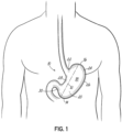
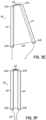
- Fig. 1 illustrates the anatomy of the stomach 10 and a resection line 12, where the resection line 12 represents a resection line for a vertical sleeve gastrectomy.
- the stomach 10 generally includes a proximal end 14, a distal end 16, an anterior side 18, and a posterior side 20. As used herein, the proximal and distal ends 14, 16 of the stomach are described from the perspective of the operative surgeon.
- the gastroesophageal junction 22 opens into the stomach 10 and is a common landmark in bariatric surgeries.
- the fundus 24 and the section of the stomach defined by the greater curvature 26 are generally the parts of the stomach 10 removed during a vertical sleeve gastrectomy.
- the remaining pouch is generally defined by the lesser curvature 28 and the resection line 12 and presents a stomach with a significantly reduced volume.
- the desired location of the resection line 12 is about 0.5 to 2 cm away from the gastroesophageal junction 22 and about 2 to 10 cm away from the pylorus 30.
- resection line guides as described herein aid in forming high quality, consistent resection lines during a medical procedure, such as a vertical sleeve gastrectomy.
- the resection line guides provide an accurate visual indication of the resection line and further provide a stabilizing engagement surface along which medical staplers may be guided during a resection procedure.
- the visualization and guiding aspects of the disclosed resection line guides are believed to result in high quality and consistent resection lines that are significantly improved over resection lines produced by current methodologies.
- the embodiments of the present invention includes a resection line guide including two clamp members capable of being operatively coupled to each other and movable relative to each other so as to provide a clamping force on an anatomical structure, such as a stomach.
- the ability of the resection line guides to generate a clamping force allows the device to be reliably positioned relative to the anatomical structure in order to eliminate or reduce the likelihood of undesirable movements of the device during a stapling operation.
- a resection line guide 40 includes a first clamp member 42 generally positionable on the anterior side 18 of the stomach 10, and a second clamp member 44 generally positionable on the posterior side 20 of the stomach 10, where the first clamp member 42 and the second clamp member 44 may be configured to be operatively coupled to effectuate a clamping force on the stomach 10.
- the first clamp member 42 and the second clamp member 44 essentially operate as a surgical clamping device for purposes described in more detail below.
- aspects of the present invention are not limited to the illustrated arrangement, where the first clamp member 42 is on the anterior side 18 of the stomach 10 and the second clamp member 44 is on the posterior side 20.
- the arrangement may be reversed such that the first clamp member 42 is on the posterior side 20 of the stomach 10 and the second clamp member 44 is on the anterior side 18 of the stomach 10 (not shown).
- Other alternative arrangements may also be possible.
- first and second clamp members 42, 44 may be configured to be operatively coupled to each other to effectuate a clamping force on an anatomical structure.
- the clamp members 42, 44 couple together at both the proximal end 14 and distal end 16 of the stomach 10.
- the clamp members 42, 44 may be coupled together using a variety of methods and engagement elements, such as that described below.
- the proximal and distal ends of one the clamp members may include a projection or pin that can be engaged or received by the proximal and distal ends of the other clamp member, respectively.
- the clamp members may be configured to connect using magnets, a clip-in connection, or other types of connections or connectors that are generally well known in the art.
- the connection method used at the proximal and distal ends of the clamp members do not need to be similar.
- the distal ends of the clamp members may be configured to connect using a clip-in connection, while the proximal end of one of the clamp members may be configured to slide through an opening on the proximal end of the other clamp member, where the opening is capable of receiving and gripping the proximal end of the one clamp member. Accordingly, there are many ways to couple the clamp members and the invention should not be limited to a certain type of connection.
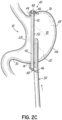
- Fig. 2B illustrates the resection line guide 40 placed around the stomach 10 with the clamp members 42, 44 coupled together at both the proximal and distal ends 14, 16 of the stomach 10.
- the second clamp member 44 may be inserted under (posterior to) the stomach 10 so that the distal end 44a of the second clamp member 44 generally extends beyond the distal end 16 of the stomach 10 and the proximal end 44b generally extends beyond the proximal end 14 of the stomach.
- the first clamp member 42 may be inserted over (anterior to) the stomach 10 using laparoscopic instruments, for example, so that the distal end 42a of the first clamp member 42 generally extends beyond the distal end 16 of the stomach 10 and the proximal end 42b generally extends beyond the proximal end 14 of the stomach 10.
- the resection line guide 40 may be put in place and used with or without having to mobilize the greater curvature. For example, a surgeon may prefer to leave the greater curvature 26 attached to the omentum (not shown), which could improve stability of the stomach 10 during stapling.
- the distal end 44a of the second clamp member 44 may be received through the distal end 42a of the first clamp member 42.
- the proximal end 44b of the second clamp member 44 may be received through the proximal end 42b of the first clamp member 42.
- the distal and proximal ends 44a, 44b may include a serrated tab 46 and the distal and proximal ends 42a, 42b may include a passage or bore 48 having an opening through which the serrated tabs 46 may pass.
- the tab 46 and bore 48 operate as a flexible ratchet capable of bringing the clamp members 42, 44 together to generate a clamping force.
- the bores 48 may be configured to prevent the serrated tabs 46 from moving backwards through the openings.
- the clamp members 42, 44 may be further manipulated so as to provide a sufficient clamping force on the stomach 10 to effectively prevent or minimize the guide 40 from moving, but without damaging the clamped tissue.
- conventional graspers may be used to pull the tabs 46 through the bores 48.
- the resection line guide 40 may include a release mechanism in the flexible ratchet that allows the tab 46 to be released from the bore 48 and thereby separate the two clamp members 42, 44. It should be appreciated that the flexible ratchet may take other forms other than that described above.
- the resection line guide 40 may be positioned relative to the stomach 10 using a two-stage clamping process.
- the first and second clamp members 42, 44 may be configured to provide a certain amount of resistance to movement of the resection line guide 40 relative to the stomach 10.
- the range of clamping force (or clamping pressure) in the first stage may be about 0.5 g/mm 2 to about 4 g/mm 2 . This resistance is configured to prevent undesirable or unintentional movements of the resection line guide 40, but yet permit the surgeon to move the resection line guide 40 to a desired position relative to the stomach 10 without significant difficulty.
- the clamping force of the resection line guide 40 may be increased to effectively prevent or minimize the guide 40 from moving relative to the stomach 10.
- the clamping force (or clamping pressure) in the second stage may be about 4 g/mm 2 to about 12 g/mm 2 .
- the clamping force (or clamping pressure) in the second stage may be about 8 g/mm 2 .
- the upper limit to which the resection line guide 40 may be clamped is selected so as to avoid any damage to the underlying tissue being clamped. This upper limit may be, for example, about 12 g/mm 2 .
- the value of about 4 g/mm 2 represents a threshold clamping force below which constitutes the first stage clamping and above which constitutes the second stage clamping. It should be recognized that these values are merely exemplary and the particular values may depend on several factors, including the anatomical structure being clamped as well as other factors. Thus, the invention should not be limited to the range of values provided herein.
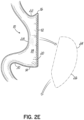
- the surgeon when the resection line guide 40 is placed on the stomach 10 (e.g., in the first clamping stage as described above), the surgeon has a clear visualization of the intended results of the vertical sleeve gastrectomy prior to actually performing the resection of the stomach 10 at the resection line 12. Hence, the surgeon has an indication of what the resultant stomach shape and volume defined by the lesser curvature 28 and the resection line 12 will likely be prior to cutting tissue. If the surgeon is not satisfied with the indication of the expected stomach shape and volume, the surgeon may adjust and manipulate the location and alignment of the resection line guide 40 prior to stapling and cutting the stomach 10.
- the resection line guide 40 should be positioned such that it does not provide lateral stretching or tension of the stomach 10, which may create an undesirable environment for stapling and cutting.
- a resection line guide such as resection line guide 40, ensures proper alignment of the resection line 12 so that the final cut with the stapler removes the fundus 24 portion, is a safe distance away from both the lesser curvature 28 and the gastroesophageal junction 22, and is squared off at the fundus 24 of the stomach to prevent or reduce the likelihood of necrotic tissue development.
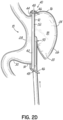
- the surgeon may then cut and staple (e.g., using a stapler conventionally used in gastrectomy procedures) the tissue using the resection line guide 40 as a track along the entire segment or a significant part of the segment until complete resection of the stomach 10 occurs, as illustrated in Figs. 2C and 2D .
- an aspect of the stapling device (such as an outer edge thereof), schematically shown as stapling device 50, may abut or engage the resection line guide 40 along an alignment surface 52 to facilitate an improved resection line.
- the outer edges of one or both of the clamp members 42, 44 may operate as an alignment surface 52 configured to securely engage the stapling device 50 and thereby provide an improved resection line 12. This may be by an abutting engagement.
- one or both of the clamp members 42, 44 may have a first connector and the stapling device 50 may have a second connector, wherein the first and second connectors are configured to movably couple the resection line guide 40 with the stapling device 50 during the resection (not shown).
- the guide 40 may include connection features (not shown) such as a weak magnetic feature to attract the stapling device 50, a channel that couples with a projection on the stapling device 50 that slides into the channel, etc.
- Fig. 2D illustrates the application of the stapling device 50 to the stomach 10 along the resection line guide 40.
- conventional staplers are generally well known in the art, such staplers will not be described herein in further detail.
- the resection line guide 40 may be secured to the stomach 10 so that it does not migrate or move once the surgeon begins stapling (e.g., the second clamping stage). Furthermore, the resection line guide 40 may be generally positioned so that it does not interfere with the activation of the stapling device 50 and ideal formation of each individual staple. As illustrated in Figs. 2A-2E , the use of the resection line guide 40 aids in creating an ideal gastric sleeve pouch size and shape ( Fig. 2E ). In an embodiment such as one described above (not covered by the subject matter of the claims) where the flexible ratchet includes a release mechanism, the surgeon may engage the release mechanism after completing the resection of the stomach 10. This allows the tab 46 to be released from the bore 48 such that the tab 46 may be moved back through and free of the bore 48. Consequently, the two clamp members 42, 44 may be separated, and the resection line guide 40 may be removed from the abdominal cavity.
- the resection line guide is provided with an articulated configuration for providing relative movement between the clamp members.
- a hinge is provided at the distal ends of the clamp members to provide pivotable relative movement therebetween.
- the hinge may be configured as a living hinge.
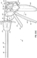
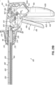
- a resection line guide 70 includes a first clamp member 72 generally positionable on the anterior side 18 of the stomach 10 and a second clamp member 74 generally positionable on the posterior side 20 of the stomach 10, where the first clamp member 72 and the second clamp member 74 may be operatively coupled to effectuate a clamping force on the stomach 10.
- the clamp members 72, 74 may be configured to be coupled at both the proximal and distal ends 14, 16 of the stomach 10.
- the distal ends of the clamp members 72, 74 is configured as a hinge joint 76.
- the hinge joint 76 may be configured as a living hinge formed by a flexible band 78 having a first end coupled to the first clamp member 72 adjacent a distal end 72a thereof and a second end coupled to the second clamp member 74 adjacent a distal end 74a thereof. With such a living hinge, pivotal movement between the clamp members 72, 74 may be achieved. As illustrated in Fig. 3A , the proximal end 74b of the second clamp member 74 may be received through the proximal end 72b of the first clamp member 72.
- the proximal end 74b of the second clamp member 74 may include a serrated tab 46 and the proximal end 72b of the first clamp member 72 may include a passage or bore 48 having an opening through which the serrated tab 46 may pass.
- the placement of the resection line guide 70 around the stomach 10 is illustrated in Fig. 3B .
- the surgeon may manipulate the resection line guide 70 across the stomach 10 so that the first clamp member 72 is generally positioned along the anterior side 18 of the stomach 10 and the second clamp member 74 is generally positioned along the posterior side 20 of the stomach 10.
- the distal ends 72a, 74a of the clamp members 72, 74 may generally extend beyond the distal end 16 of the stomach 10 and the proximal ends 72b, 74b of the clamp members 72, 74 may generally extend beyond the proximal end 14 of the stomach 10.
- the flexible band 78 between the clamp members 72, 74 may loop or extend around the distal end 16 of the stomach 10, as illustrated in Fig. 3B (not covered by the subject matter of the claims).
- the clamp members 72, 74 may be manipulated so as to provide a clamping force on the stomach 10.
- the clamp members 72, 74 may be pivoted relative to each other in order to position the resection line guide 70 relative to the stomach 10.
- the proximal end 72b of the first clamp member 72 and the proximal end 72b of the second clamp member 74 may be coupled.
- the serrated tab 46 may be pulled through the bore 48 at the proximal end 72b of the first clamp member 72, such as with conventional graspers.
- the securement of the resection line guide 70 to the stomach 10 may be achieved using the two-stage clamping process as described above. More particularly, the tab 46 may be pulled through bore 48 so as to generate a clamping force on the stomach 10 less than the threshold clamping force.
- This first-stage clamping force is configured and selected to provide a certain amount of resistance to movement of the resection line guide 70 relative to the stomach 10. This resistance is configured to prevent undesirable or unintentional movements of the resection line guide 70, but yet permit the surgeon to move the resection line guide 70 to a desired position relative to the stomach 10 without significant difficulty.
- the clamping force of the resection line guide 70 may be increased above the threshold clamping force to effectively prevent or minimize the resection line guide 70 from moving relative to the stomach 10.
- the upper limit to which the resection line guide 70 may be clamped is selected so as to avoid any damage to the underlying tissue being clamped. This may be achieved in this embodiment, for example, by pulling the tab 46 further through the bore 48.
- the surgeon When the resection line guide 70 is placed on the stomach 10 (e.g., in the first clamping stage as described above), the surgeon has a clear visualization of the intended results of the vertical sleeve gastrectomy prior to actually performing the resection of the stomach 10 at the resection line 12. Hence, the surgeon has an indication of what the resultant stomach volume defined by the lesser curvature 28 and the resection line 12 will be prior to cutting tissue. If the surgeon is not satisfied with the indication of the expected stomach volume, the surgeon may adjust and manipulate the location and alignment of the guide prior to stapling and cutting the stomach 10.
- the surgeon may then cut and staple the tissue using the resection line guide 70 as a track along the entire segment or a significant part of the segment until complete resection of the stomach 10 occurs.
- the stapling device 50 may abut or engage the resection line guide 70 along an alignment surface to facilitate an improved resection line, similar to that shown above in Fig. 2D .
- the hinge that connects the first and second clamping members may take the form of a selectively formable hinge which may, for example, be formed internal to the abdominal cavity to provide pivotable relative movement between the clamp members.
- a resection line guide 54 includes a first clamp member 56 generally positionable on the anterior side 18 of the stomach 10 and a second clamp member 58 generally positionable on the posterior side 20 of the stomach 10, where the first clamp member 56 and the second clamp member 58 may be operatively coupled to effectuate a clamping force on the stomach 10.
- the clamp members 56, 58 may be configured to be coupled at both the proximal and distal ends 14, 16 of the stomach 10 (although the proximal end connection is not shown). More particularly, the distal ends of the first and second clamp members 56, 58 may be configured as a formable hinge joint.
- the distal end of the second clamp member 58 may include a ring or eyelet 57 having an opening
- the distal end of the first clamp member 56 may include a hook 59. With the hook 59 positioned within the eyelet 57, the hinge joint is assembled and pivotal movement between the clamp members 56, 58 may be achieved.
- the proximal ends of the clamp members 56, 58 may be configured to be coupled.
- the proximal end of the second clamp member 58 may include a serrated tab and the proximal end of the first clamp member 56 may include a passage or bore having an opening through which the serrated tab may pass, similar to that above.
- Other types of connections at the proximal ends are also possible.
- the second clamp member 58 may be inserted under (posterior to) the stomach 10 so that the distal end of the second clamp member 58 generally extends beyond the distal end 16 of the stomach 10 and the proximal end generally extends beyond the proximal end 14 of the stomach 10.
- the first clamp member 56 may be inserted over (anterior to) the stomach 10 using laparoscopic instruments, for example, so that the distal end of the first clamp member 56 generally extends beyond the distal end 16 of the stomach 10 and the proximal end generally extends beyond the proximal end 14 of the stomach 10.
- the distal end of the second clamp member 58 may be configured to flex or bend so that the distal end extends upwardly and around the distal end 16 of the stomach 10.
- the hook 59 at the distal end of the first clamp member 56 may be engaged within the eyelet 57, thereby forming the hinge joint. This may be accomplished, for example, with conventional graspers (not shown).
- Being able to assemble the resection line guide 54 inside the abdominal cavity may be advantageous in that it may allow for smaller trocars to be used because the entire guide does not have to fit simultaneously through a single trocar.
- the clamp members 56, 58 may be pivoted relative to each in order to position the resection line guide 54 relative to the stomach 10.
- the proximal end of the first clamp member 56 and the proximal end of the second clamp member 58 may be coupled (not shown).
- the securement of the resection line guide 54 to the stomach 10 may be achieved using the two-stage clamping process as described above.
- the first-stage clamping force is less than a threshold clamping force and is configured and selected to provide a certain amount of resistance to movement of the resection line guide 54 relative to the stomach 10.
- This resistance is configured to prevent undesirable or unintentional movements of the resection line guide 54, but yet permit the surgeon to move the resection line guide 54 to a desired position relative to the stomach 10 without significant difficulty.
- the clamping force of the resection line guide 54 may be increased above the threshold clamping force to effectively prevent or minimize the resection line guide 54 from moving relative to the stomach 10.
- the upper limit to which the resection line guide 54 may be clamped is selected so as to avoid any damage to the underlying tissue being clamped.
- the surgeon When the resection line guide 54 is placed on the stomach 10 (e.g., in the first clamping stage as described above), the surgeon has a clear visualization of the intended results of the vertical sleeve gastrectomy prior to actually performing the division of the stomach 10 at the resection line 12. Hence, the surgeon has an indication of what the resultant stomach volume defined by the lesser curvature 28 and the resection line 12 will be prior to cutting tissue. If the surgeon is not satisfied with the indication of the expected stomach volume, the surgeon may adjust and manipulate the location and alignment of the resection line guide 54 prior to stapling and cutting the stomach 10.
- the surgeon may then cut and staple the tissue using the resection line guide 54 as a track along the entire segment or a significant part of the segment until complete resection of the stomach 10 occurs.
- the stapling device 50 may abut or engage the resection line guide 54 along an alignment surface to facilitate an improved resection line, similar to that shown above in Fig. 2D .
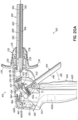
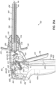
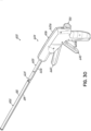
- a resection line guide 60 includes a first clamp member 62 generally positionable on the anterior side 18 of the stomach 10 and a second clamp member 64 generally positionable on the posterior side 20 of the stomach 10, where the first clamp member 62 and the second clamp member 64 are operatively coupled to effectuate a clamping force on the stomach 10.
- the clamp members 62, 64 are configured to be coupled at both the proximal and distal ends 14, 16 of the stomach 10.
- the distal ends of the clamp members 62, 64 are configured as a hinge joint.
- the distal ends 62a, 64a of the clamp members 56, 58 may be coupled by the spring hinge 66, which allows for pivotal movement between the clamp members 62, 64.
- Spring hinges are generally well known in the art and thus will not be described in further detail herein.
- the proximal ends 62b, 64b of the clamp members 62, 64 are configured to be coupled. More particularly, the proximal ends 62b, 64b are coupled by a flexible member 68. Aspects of the flexible member according to the present embodiment are described in more detail below. Other types of connections at the proximal ends of the first and second clamp members 62, 64 are also possible, but not covered by the subject matter of the claims
- the resection line guide 60 may be placed around the stomach 10.
- the surgeon may manipulate the resection line guide 60 across the stomach 10 so that the first clamp member 62 is generally positioned along the anterior side 18 of the stomach 10 and the second clamp member 64 is generally positioned along the posterior side 20 of the stomach 10.
- the distal ends 62a, 64a of the clamp members 62, 64 generally extend beyond the distal end 16 of the stomach 10 and the proximal ends 62b, 64b of the clamp members 62, 64 generally extend beyond the proximal end 14 of the stomach 10.
- the spring hinge 66 between the first and second clamp members 62, 64 may extend around the distal end 16 of the stomach 10.
- the clamp members 62, 64 may be pivoted relative to each in order to position the resection line guide 60 relative to the stomach 10. This may be done, for example, with conventional graspers.
- the ends of the flexible member 68 may be pulled, which tensions the flexible member 68 and decreases the length of the flexible member 68 that is between the clamp members 62, 64.
- the proximal ends 62b, 64b of the clamp members 62, 64 move towards each other, and the clamp members 62, 64 begin to provide a clamping force on the stomach 10.
- the securement of the resection line guide 60 to the stomach 10 may be achieved using the two-stage clamping process as described above.
- the first-stage clamping force is less than a threshold clamping force and is configured and selected to provide a certain amount of resistance to movement of the resection line guide 60 relative to the stomach 10. This resistance is configured to prevent undesirable or unintentional movements of the resection line guide 60, but yet permit the surgeon to move the resection line guide 60 to a desired position relative to the stomach 10 without significant difficulty.
- the clamping force of the resection line guide 60 may be increased above the threshold clamping force to effectively prevent or minimize the resection line guide 60 from moving relative to the stomach 10.
- the upper limit to which the resection line guide 60 may be clamped is selected so as to avoid any damage to the underlying tissue being clamped. This may be achieved by pulling further on the ends of the flexible member 68, which increases the tension on the flexible member 68 and increases the clamping force provided by the clamp members 62, 64.
- the surgeon When the resection line guide 60 is placed on the stomach 10 (e.g., in the first clamping stage as described above), the surgeon has a clear visualization of the intended results of the vertical sleeve gastrectomy prior to actually performing the division of the stomach 10 at the resection line 12. Hence, the surgeon has an indication of what the resultant stomach volume defined by the lesser curvature 28 and the resection line 12 will be prior to cutting tissue. If the surgeon is not satisfied with the indication of the expected stomach volume, the surgeon may adjust and manipulate the location and alignment of the resection line guide 60 prior to stapling and cutting the stomach 10.
- the surgeon may then cut and staple the tissue using the resection line guide 60 as a track along the entire segment or a significant part of the segment until complete resection of the stomach 10 occurs.
- the stapling device 50 may abut or engage the resection line guide 60 along an alignment surface to facilitate an improved resection line, similar to that shown above in Fig. 2D .
- the flexible member 68 may extend through substantially the full length of the clamp members 62, 64 such that it extends between the distal ends 62a, 64a of the clamp members 62, 64 along with the spring hinge 66.
- This arrangement of the flexible member 68 is shown in phantom in Figs. 3E and 3F . This type of arrangement of the flexible member 68 is also described in more detail below.
- the operation of this alternative embodiment is similar to that described above for Figs. 3E and 3F .
- the resection line guide may have a pair of clamp members coupled by an elongate flexible member capable of being tensioned so as to produce a clamping force on an anatomical structure, such as stomach 10.
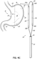
- Figs. 4A-4C illustrate such an embodiment.
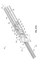
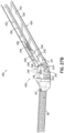
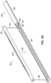
- the resection line guide 80 includes a first clamp member 82 generally positionable on the anterior side 18 of the stomach 10 and a second clamp member 84 generally positionable on the posterior side 20 of the stomach 10, where the first clamp member 82 and the second clamp member 84 may be operatively coupled by a flexible member 86 to effectuate a clamping force on the stomach 10.
- the flexible member 86 may include a flexible cable.
- the clamp members 82, 84 may be configured as hollow bodies having a generally rectangular cross section and a length in a longitudinal direction which may exceed the length of the stomach 10 along the resection line 12.
- the clamp members 82, 84 may be generally solid.
- the cross-sectional shape of the clamp members may also differ, as is noted below.
- each of the clamp members 82, 84 may be a unity, monolithic member.
- the clamp members 82, 84 may be formed from a plurality of individual clamp segments that collectively form a clamp member. Such an embodiment, which is discussed below in greater detail, may allow the length of a clamp member to be easily varied.
- each of the clamp members 82, 84 may include openings 88 at their distal ends 82a, 84a and proximal ends 82b, 84b (or through bores in the case of solid clamp members) so as to allow the flexible member 86 to extend through and along the length of the clamp members 82, 84.
- the clamp members 82, 84 are essentially threaded onto the flexible member 86.
- the clamp members 82, 84 are also generally movable relative to the flexible member 86, such as along the length thereof.
- the flexible member 86 does not have to extend through (e.g., internal of) the clamp members 82, 84, but may extend along an outer surface of the clamp members 82, 84, such as through eyelets or the like positioned along a surface of the clamp members 82, 84 (not shown).
- both clamp members 82, 84 do not have to be movable along the flexible member 86.
- one of the clamp members 82, 84 may be fixed relative to the flexible member 86 and the other of the clamp members 82, 84 may be movable relative to the flexible member 86.
- Figs. 4A and 4B illustrate the placement of the resection line guide 80 around the stomach 10.
- the surgeon may manipulate the flexible member 86 around the distal end 16 of the stomach 10 without having one or both clamp members 82, 84 thereon.
- the surgeon may then thread or manipulate the second clamp member 84 onto an end of the flexible member 86 and slide the second clamp member 84 along the flexible member 86 until the second clamp member 84 is generally positioned on the posterior side 20 of the stomach 10.
- the distal end 84a may generally extend beyond the distal end 16 of the stomach 10 and the proximal end 84b may generally extend beyond the proximal end 14 of the stomach 10.
- the surgeon may thread or manipulate the first clamp member 82 onto the flexible member 86 such that the first clamp member 82 is generally positioned on the anterior side 18 of the stomach 10.
- the first clamp member 82 may be threaded or manipulated onto the other end of the flexible member 86.
- the distal end 82a may generally extend beyond the distal end 16 of the stomach 10 and the proximal end 82b may generally extend beyond the proximal end 14 of the stomach 10.
- the order of applying the clamp members onto the flexible members may be reversed. Being able to assemble the resection line guide 80 inside the abdominal cavity may be advantageous in that it may allow for smaller trocars to be used because the entire guide does not have to fit simultaneously through a single trocar.
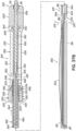
- the resection line guide 94 may be pre-assembled and then inserted into the abdominal cavity as a unit.
- the surgeon may manipulate the guide 94 across the stomach 10 so that the first clamp member 96 is generally positioned along the anterior side 18 of the stomach 10 and the second clamp member 98 is generally positioned along the posterior side 20 of the stomach 10.
- the distal ends 96a, 98a of the clamp members 96, 98 generally extend beyond the distal end 16 of the stomach 10 and the proximal ends 96b, 98b of the clamp members 96, 98 generally extend beyond the proximal end 14 of the stomach 10.
- the section of the flexible member 86 between the clamp members 96, 98 may be loop or extend around the distal end 16 of the stomach 10, as illustrated in Fig. 4B .
- the clamp members 96, 98 may be manipulated so as to provide a clamping force on the stomach 10. This clamping may be achieved by tensioning the flexible member 86.
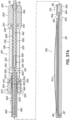
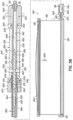
- the resection line guides 80, 94 may include a device for tensioning the flexible member 86 thereby providing a clamping force on the anatomical structure, such as the stomach 10 (the process being described below with reference to resection line guide 80).
- a tensioning device may include a tube 90 that operates in conjunction with the flexible member 86 and clamp members 82, 84 to generate a clamping force between the clamp members 82, 84.
- the flexible member 86 may extend through the tube 90 such that, for example, the ends thereof may be positioned outside the body, and thereby be more easily manipulated by the surgeon. The ends of the flexible member 86 may also remain within the abdominal cavity. In any event, the surgeon may then pull on the ends of the flexible member 86 while the end 92 of the tube 90 pushes against the proximal ends 82b, 84b of the clamp members 82, 84, which are not permitted to pass into the tube 90. When the flexible member 86 is initially pulled, slack in the flexible member 86 is thereby taken up and the clamp members 82, 84 move towards each other.
- the clamping force on the stomach 10 begins to increase along the length of the clamp members 82, 84.
- the length of the intermediate segment of the flexible member 86 between the clamp members 82, 84 decreases.
- tensioning the flexible member 86 also generally aligns the clamp members 82, 84.
- tension in the flexible member 86 may generally vertically align the clamp members 82, 84 relative to the stomach 10.
- the clamp members 82, 84 may slide along the flexible member 86 during this tensioning.
- the securement of the resection line guides 80, 94 to the stomach 10 may be achieved using the two-stage clamping process as described above. More particularly, the flexible member 86 may be pulled so as to generate a clamping force on the stomach 10 less than the threshold clamping force. Again, this first-stage clamping force is configured and selected to provide a certain amount of resistance to movement of the resection line guide 80 relative to the stomach 10. This resistance is configured to prevent undesirable or unintentional movements of the resection line guide 80, but yet permit the surgeon to move the resection line guide 80 to a desired position relative to the stomach 10 without significant difficulty.
- the clamping force of the resection line guide 80 may be increased above the threshold clamping force to effectively prevent or minimize the resection line guide 80 from moving relative to the stomach 10.
- the upper limit to which the resection line guide 80 may be clamped is selected so as to avoid any damage to the underlying tissue being clamped. This may be achieved in this embodiment by pulling the ends of the flexible member 86 while pushing further against the proximal ends 82b, 84b of the clamp members 82, 84 using the tube 90.
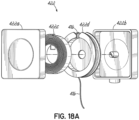
- a resection line guide 180 may include a light source configured to cooperate with a light collector or sensor to provide an indication of tissue thickness.
- a resection line guide 180 includes a first clamp member 182 and a second clamp member 184 coupled by a living hinge 186, similar to that shown in Figs. 3A and 3B above.
- the second clamp member 184 When placed on the stomach 10, the second clamp member 184 may be generally positioned on the posterior side 20 of the stomach 10, and the first clamp member 182 may be generally positioned on the anterior side 18 of the stomach 10.
- the second clamp member 184 may be made from a transparent or material, such as a transparent plastic like polycarbonate or other suitable biocompatible material, and include one or more light sources 188 configured to emit light into the tissue being clamped.
- the light sources may include a series of LEDs spaced along the second clamp member 184. It should be appreciated, however, that the light source can be other suitable sources for emitting light.
- At least a portion of the light from the light source 188 is transmitted through the stomach tissue and is received at the first clamp member 182.
- At least a portion of the first clamp member 182 may be transparent and include one or more light sensors 190 configured to measure the amount of light being received.
- the amount of light received at the sensors 190 may have a determinable correlation to the thickness of the tissue through which the light is transmitted.
- the resection line guide 180 may be operatively coupled to a controller or other processor (not shown) capable of determining the tissue thickness based upon the amount of light emitted by the light source 188 and that received by sensors 190. Such a thickness determination may aid the surgeon in choosing the proper staple size along the resection line 12.
- the flexible member may take several forms.
- the flexible member may include a wire, suture, thread, chain, or other elongate flexible member.
- the flexible member may be made of metal, plastic, or any other material that is suitable for a biological environment.
- the flexible member may be, for example, a braided cable.
- the flexible member should be capable of a radius of bend of approximately 0,0762 cm (approx.. 0.030 inches) and further be generally resistant to kinking, knotting, etc.
- the flexible member should be able to accommodate a tensile load sufficient to generate a clamping force (pressure) above the maximum clamping force expected to be imposed during a procedure.
- the flexible member should be able to accommodate a tensile load sufficient to create a clamping force of about 12 g/mm 2 on the anatomical structure.
- the flexible member should be able to accommodate a tensile load of between about 11 to 23 kg (about 25 to 50 lbs).
- the flexible member may be a multi-strand stainless steel cable or a polymer, such as vectran.
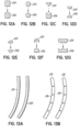
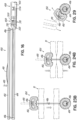
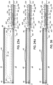
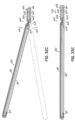
- FIGs. 11A-11C are schematic illustrations of exemplary configurations (not covered by the subject matter of the claims) of two clamp members 192, 194 and a flexible member 196 configured to be tensioned so as provide a clamping force between the clamp members 192, 194.
- the flexible member 196 has a first end 196a which is fixed to clamp member 194 adjacent a distal end 194a thereof and passes through the second clamp member 194 adjacent the distal end 194a.
- Flexible member 196 then passes through the first clamp member 192 adjacent a distal end 192a thereof and through and out of the first clamp member 192 adjacent a proximal end 192b thereof.
- the second end 196b of the flexible member 196 may be positioned outside the body and pulled or otherwise manipulated by the surgeon so as to increase the tension in the flexible member 196, and thereby generate a clamping force between clamp members 192, 194.
- the flexible member 196 has a first end 196a which is fixed to the second clamp member 194 adj acent the proximal end 194b thereof and passes through the second clamp member 194 adjacent the proximal end 194b thereof.
- the flexible member 196 then passes through the first clamp member 194 adjacent a proximal end 192b thereof, through the first clamp member 192, out of the first clamp member 192 adjacent the distal end 192a thereof, into the second clamp member 194 adjacent the distal end 194a thereof, through the second clamp member 194, and out the proximal end 194b of clamp member 194.
- the second end 196b of the flexible member 196 may be positioned outside the body and pulled or otherwise manipulated by the surgeon so as to increase the tension in the flexible member 196, and thereby generate a clamping force between the clamp members 192, 194.
- the flexible member 196 is fixed to the second clamp member 194 adjacent a proximal end 194b thereof and extends along the length of the second clamp member 194 toward the distal end 194a.
- the flexible member 196 passes out of the second clamp member 194 adjacent the distal end 194a thereof and passes into the first clamp member 192 adjacent the distal end 192a thereof.
- the flexible member 196 extends along the length of the first clamp member 192 and out of the first clamp member 192 adjacent the proximal end 192b thereof. The flexible member 196 then passes back into the second clamp member 194 adjacent the proximal end 194b thereof and out the proximal end 194b of second clamp member 194.
- the second end 194b may be positioned outside the body and pulled or otherwise manipulated by the surgeon so as to increase the tension in the flexible member 196, and thereby generate a clamping force between the clamp members 192, 194.
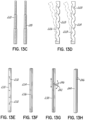
- FIGs. 11D-11E are schematic illustrations of exemplary configurations of two clamp members 192, 194 and two flexible members 196, 198 configured to be tensioned so as provide a clamping force between the clamp members 192, 194.
- a first flexible member 196 has a first end 196a fixed to the first clamp member 192 adjacent the distal end 192a thereof and passes out of the first clamp member 192 adjacent the distal end 192a thereof.
- the first flexible member 196 then passes into the second clamp member 194 adjacent a distal end 194a thereof and extends along the second clamp member 194 and out of the proximal end 194b thereof.
- the second end 194b of the first flexible member 196 may be positioned outside the body.
- the arrangement further includes a second flexible member 198 having a first end 198a fixed to the first clamp member 192 adjacent the proximal end 192b thereof and passes out of the first clamp member 192 adjacent the proximal end 192b thereof.
- the second flexible member 198 then passes into the second clamp member 194 adjacent a proximal end 194b thereof and passes out of the proximal end 194b thereof.
- the second end 198b of the second flexible member 198 may be positioned outside the body.
- the second ends 196b, 198b may be pulled or otherwise manipulated by the surgeon so as to increase the tension in the flexible members 196, 198 and thereby generate a clamping force between the clamp members 192, 194.
- this arrangement provides for independent control of the clamping force of the proximal and the distal ends of the resection line guide.
- increasing the tension in the first flexible member 196 will draw the distal ends 192a, 194a of clamp members 192, 194 towards each other.
- the clamping force at the distal end of the resection line guide increases.
- Fig. 11E illustrates the resection line guide according to the embodiment in Fig. 11D where the distance between the distal ends 192a, 194a of the clamp members 192, 194 is less than the distance between the proximal ends 192b, 194b creating an overall shape of the resection line guide that is generally trapezoidal.
- the clamp members 192, 194 may be in non-parallel relation.
- the clamping force at the distal end of the resection line guide may be greater than the clamping force at the proximal end of the resection line guide when the resection line guide is placed around an anatomical structure.
- This ability to independently control the clamping force along the proximal and distal ends of the resection line guide may be advantageous in certain applications.
- independently controlling the clamping force along the proximal and distal ends of the resection line guide may be advantageous where the tissue thickness of the anatomical structure varies along the length of the resection line.
- the distal end 14 of the stomach 10 generally has a thickness less than that of the proximal end 16 of the stomach 10.
- the ranges of clamping force used in the two-stage clamping process may vary at the distal and proximal ends 14, 16 of the stomach 10.
- a resection line guide capable of providing a varying clamping force along the length of, for example, the stomach 10 may aid in creating an improved resection line.
- a first flexible member 196 is coupled to first and second clamp members 192, 194 in a manner similar to that described above for resection line guides 80, 94.
- this embodiment further includes a second flexible member 198 coupled to the first and second clamp members 192, 194 in a manner similar to that described above for guides 80, 94.
- the first flexible member 196 extends through the first and second clamp members 192, 194 adjacent a first edge 200 thereof and the second flexible member 198 extends through the first and second clamp members 192, 194 adjacent a second edge 202 thereof.
- This arrangement advantageously provides for independent control of the right and the left sides of the resection line guide.
- increasing the tension in the first flexible member 196 will increase the clamping force at the left side of the resection line guide.
- increasing the tension in the second flexible member 198 will increase the clamping force at the right side of the resection line guide. This ability to control the clamping force along the right and left sides of the resection line guide may be advantageous in certain applications.
- the length of the clamp members have been described as generally exceeding the length of the anatomical structure being clamped (e.g., stomach, lung, kidney, liver, etc.), the invention is not so limited. More particularly, the lengths of the clamping members may vary depending on the specific application to be greater or less than the length of the anatomical structure being clamped. Additionally, the first and second clamp members do not have to be of equal lengths, but may have different lengths. In exemplary embodiments, the two clamp members may be formed from plastic, metal, or other materials suitable for providing a clamping force in a biological environment (i.e., must be biologically compatible). The clamp members may be configured to distribute the clamping force provided to the anatomical structure across the length of the clamp members.
- the clamp members may be generally rigid. As noted above, the clamp members may be hollow, solid, partially hollow, or have other configurations. In the embodiments discussed herein, the two clamp members are illustrated as elongate members having a certain cross-section. However, the clamp members may have a variety of cross-sectional shapes, some of which are illustrated in Figs. 12A-12E . By way of example, the two clamp members 204, 206 may have cross-sectional shapes that are rectangular ( Fig. 12A ), cylindrical ( Fig. 12B ), V-shaped ( Fig. 12C ), half-moon ( Fig. 12D-E ), or wavy ( Fig. 12G ). The two clamp members 204, 206 may have the same or different cross-sectional shapes.
- Fig. 12F illustrates an embodiment where the clamp member 204 may have a crescent cross-sectional shape, while the clamp member 206 may have a half-moon cross-sectional shape.
- the two clamp members may be formed as a unitary member or may be formed from a plurality of clamp segments as previously described.
- the surfaces of the clamp members that engage with the anatomical structure may be textured to enhance the securement of the resection line guide to the anatomical structure.
- these surfaces may include a traction pattern that facilitates the resistance of movement of the resection line guide relative to the underlying tissue.
- the traction pattern may be formed, for example, by ridges and grooves.
- the ridges and grooves may be directed generally in the axial direction, the longitudinal direction, or in crisscrossed pattern.
- the surfaces may be roughened, for example, with various post-processing methods generally known in the art. Other textured patterns may also be possible.
- the clamp members may have a longitudinal shape other than straight.
- This may be beneficial where the surgeon wants to create a non-linear resection line.
- the surgeon may want to create a curved resection line that reflects the lesser curvature 28 of the stomach 10.
- Fig. 13A (not covered by the subject-matter of the claims) illustrates an exemplary embodiment where the two clamp members 208, 210 may be generally arcuate or curved so as to generally correspond to the shape of the lesser curvature 28 of the stomach 10.
- two clamp members 212, 214 may be made of segments connected by a tape 216 or other spine generally running the length of the two clamp members 212, 214.
- the tape 216 on the side of the segments facing anatomical right, the sides of the segments facing the anatomical left may generally bend and flex outwardly, as illustrated in Fig. 13B .
- the segments may be sized based on a staple cartridge. By way of example, if the segments were between about 50 mm and about 60 mm in length, a curved resection line may be made by using one 60 mm staple cartridge per segment.
- the two clamp members 218, 220 may have a telescopic configuration (e.g., nested sections), as illustrated in Fig. 13C , such that the length of the two clamp members 218, 220 may be easily varied to meet the needs of a specific application.
- the two clamp members 224, 226 may be configured to be rigid in the longitudinal direction but malleable in a transverse direction.
- the clamp members 224, 226 may include a series of cut-outs or notches 228 that facilitate flexing or bending of the clamp members 224, 226 in a generally transverse direction (e.g., left and right in the reference frame of Fig. 13D ).
- each clamp member 224, 226 may include a mechanism allowing for external control of the transverse movement of the clamp members 224, 226.
- each clamp member 224, 226 may have one or more control lines coupled to one or more locations along the clamp members 224, 226 that allow the clamp members to be flexed in a certain manner.
- the control lines may include flexible, or rigid, or semi-rigid cables.
- tightening one of the flexible members may cause the clamp members 224, 226 to flex.
- the device for tensioning the flexible member should provide a sufficient clamping force for securing the guide onto the anatomical structure.
- the tensioning device should be configured to implement the two-stage clamping described above.
- a variety of tensioning devices may be used to provide a tension in the flexible member in order to secure the resection line guide onto the anatomical structure.
- a cinch tube can be used in conjunction with the flexible member and clamp members to generate a tension in the flexible member.
- a tensioning mechanism for tightening the flexible member may include a tightener having a plunger, where the plunger may be lifted to slide the flexible member through and may be released to hold the flexible member in place.
- the tensioning device may be configured to move over and rest on the clamp members, such as at a proximal end thereof. Holding the clamp members together in this way may provide increased tension or secure the clamp members in order to generate the clamping force.
- Fig. 13E illustrates an exemplary embodiment (not covered by the subject matter of the claims) of a clamp member 230 (only one shown) having a series of markings 232 along the length of a clamp member 230 configured to provide an indication of distance.
- markings 232 may be used to mark off distance, for example, in centimeters.
- the markings 232 may be used to mark off or estimate the number of staple firings that will be needed to resection the anatomical structure.
- staple cartridges of 60 mm are commonly used.
- markings 232 spaced 60 mm apart may be used along the clamp member 230. Using these markings, the surgeon may quickly assess how many staple cartridges will be needed to complete the resection.
- certain embodiments may provide an indication of the distance from the resection line guide to certain anatomical landmarks.
- anatomical landmarks are typically referred to when establishing the ideal resection line, it may be beneficial to know, or be able to more accurately estimate, the distance of the resection line guide to those landmarks.
- a clamp member of a resection line guide may have a fixed and known width (e.g., 1 cm in width). Because the resection line is frequently 1 cm away from the gastroesophageal junction 22, using a 1 cm wide clamp member that rests against the gastroesophageal junction 22 would assure a proper spacing from this anatomical landmark.
- the clamp member may have markings indicating a specific width.
- a clamp member 234 may be wider than 1 cm where a marking 236 may be included along the length of the clamp member 234 indicating a width of 1 cm, such as from one of the side edges thereof.
- the resection line guide may include an adjustable measuring device capable of providing a physical scale for determining or estimating distance from the resection line guide.
- Fig. 13G illustrates an embodiment where a clamp member 238 includes a measuring arm 240 coupled to the clamp member 238.
- the measuring arm 240 may be movably coupled, e.g., such as pivotally coupled to the clamp member 238.
- the measuring arm 240 may have a known and pre-determined length.
- the measuring arm 240 may include markings 246 indicating distance. This would allow the surgeon to pivot the measuring arm 240 away from the clamp member 238 and use the measuring arm 240 to determine or estimate the distance from the resection line guide to various anatomical landmarks.
- a pivotable arm may have a length of about 2 cm to about 6 cm.
- the length of the measuring arm 240 may be variable. More than one of these components may be used the clamp member 238.
- the measuring arm may be movable, e.g., slidable, along the length of the clamp member 238, as is illustrated in Fig. 13G .
- the measuring arm 240 may slide within a longitudinal groove in the clamp member 38.
- electronic distance measurement may be possible.
- a reference point may be established on a clamp member and the other reference point may be associated with a laparoscopic instrument. In this way, as the instrument moves within the abdomen, electronic feedback may be provided to indicate the distance between the two reference points.
- the clamp member and instrument may be operatively coupled to a controller to provide the distance measurement.
- Certain embodiments may provide an indication of the thickness of the anatomical structure to be stapled. This may be accomplished using a variety of methods.
- a light source is used to indicate the thickness of an anatomical structure.
- a clamp member 244 may include longitudinal markings 246 indicating the distance from the lower edge of the clamp member facing the anatomical structure to be resected.
- Fig. 13H illustrates three longitudinal markings 246 along a side wall of a clamp member 244. These markings may be, for example, markings of distance or markings based on staple leg lengths. In practice, different staple leg lengths often have corresponding colors depending on their manufacturer.
- the markings, and their spacing, may be based on these colors to indicate what staple size should be used.
- blue, green, and black lines may be used to indicate staple leg lengths of 3.5 mm, 4.1 mm, and 4.4 mm, respectively.
- a surgeon may use the markings as a scale on which to base a determination or estimate of the thickness of the tissue of the anatomical structure.
- the surgeon may compare the thickness of tissue that has already been, for example, stapled with the distances indicated by the longitudinal markings. The surgeon may then choose a staple leg length for the next application of the stapler based on the estimate of the tissue thickness at that location along the anatomical structure.
- an indicator window may be used showing an indicator bar that moves based on the length of flexible member between the clamp members. This may be used for a single flexible member or for two thicknesses based on a flexible member at each of the distal and proximal ends of the resection line guide.
- the resection line guide may be capable of measuring the distance between clamp members using ultrasound.
- an indication of the distance between the two clamp members at the distal and proximal ends of the resection line guide may indicate tissue thickness at the distal and proximal ends 14, 16 of the stomach 10.
- Certain embodiments may be capable of measuring the clamping force provided by the resection line guide. This may be accomplished using any suitable method known in the art.
- An embodiment of a resection line guide may include a flexible member and a strain gauge to measure the amount of strain on the flexible member. In embodiments where the guide is applying varying pressure on the anatomical structure, there may be more than one device capable of measuring the clamping force.
- PVDF piezoelectric film or Mylar film may be included in the resection line guide.
- a medical device 400 includes a resection line guide 402, which may be one of the guides described with reference to Figs. 3E,3F above, operatively coupled to a manipulator 404.
- the manipulator 404 includes a shaft 408 coupled to a handpiece, such as a pistol-grip device 406, at one end and the resection line guide 402 at the other end thereof.
- the resection line guide 402 and a portion of the shaft 408 may be inserted into the patient, such as via a trocar.
- the surgeon may then manipulate the resection line guide 402 and/or articulate the resection line guide 402 relative to the manipulator 404 to perform the procedure.
- embodiments of the present invention may include mechanisms for effectuating a surgical procedure with the resection line guide 402 and for allowing the resection line guide 402 to articulate relative to the shaft 408.
- the resection line guide 402 includes clamp members 412, 414 that are movably coupled together via a flexible member 416.
- the flexible member 416 passes through hollow portions of the clamp members 412, 414 so that, for example, the clamp member 412 may be separated from or brought closer to the clamp member 414.
- an anchor 417 fixes a first end of the flexible member 416 to the clamp member 414 adjacent a proximal end thereof, and the flexible member 416 passes out of a bore adjacent a proximal end of the clamp member 414 into the clamp member 412 adjacent a proximal end thereof.
- Flexible member 416 passes through and out of the clamp member 412 adjacent a distal end thereof.
- Flexible member 416 then passes into the clamp member 414 adjacent a distal end thereof and through the clamp member 414 into the shaft 408. Retraction of the flexible member 416 moves at least one of the clamp members 412, 414 as is shown generally by arrow 418 in Figs. 15A and 16 and described below.
- the clamp members 412, 414 may have mating surfaces, as shown in Figs. 23B, 24B, and 29 . In the present embodiment, the mating surfaces are illustrated as the ridged surfaces on the clamp members 412, 414.
- the ridged surface on the clamp member 412 is capable of mating with the ridged surface on the clamp member 414 in multiple locations.
- the resection line guide 402 may include other bores similar to the bore 413 on one or both of the proximal and distal ends of one or both of the clamp members 412, 414.
- the resection line guide 402 may include a tab 410, which extends from the clamp member 412 by which the surgeon may manipulate the orientation of the resection line guide 402. It will be appreciated that a tab may also be mounted on the clamp member 414. This may allow for more controlled separation of the clamp members 412, 414. Alternatively, instead of a tab on one or both of the clamp members 412, 414, another element capable of being engaged by a laparoscopic instrument may extend from or be mounted to one or both of the clamp members 412, 414. By way of example, a flexible cable or a coupling area may be attached or formed in one of the clamp members 412, 414 with which a laparoscopic instrument may engage.
- a coupling area may include a magnet or may be a recess in which a laparoscopic instrument may be configured to clip or snap.
- the resection line guide 402 includes one of resection line guides described above, shown in Figs. 3E, 3F .
- the manipulator 404 includes mechanisms that the surgeon may manipulate to independently move the resection line guide 402 to open and close the clamp members 412, 414 and/or to pivot the resection line guide 402 relative to the manipulator 404, as is described in detail below.
- the manipulator 404 includes a case or housing formed by halves 420a, 420b that contains mechanisms for operation of the medical device 400.
- the flexible member 416 extends from shaft 408 and is fixed to a spring reel 422.
- the spring reel 422 may include a case or housing formed by halves 422a, 422b that contains a spiral spring 422c and a spool 422d of the flexible member 416 onto which the flexible member 416 may be wound and unwound.
- the spring reel 422 may have a force constant of 0,045 to 0,45 kg (0.1 to 1 lb).
- the spring reel 422 is therefore configured to release a length of the flexible member 416 and/or take up a length of the flexible member 416 as is generally understood by one of ordinary skill in the art.
- the manipulator 404 includes a brake mechanism 426 that is capable of frictionally capturing the flexible member 416 to prevent its unintentional movement relative to the brake mechanism 426, such as unintentional extension of the flexible member 416 from the spring reel 422.
- the brake mechanism 426 includes a brake lever 428 that is pivotally coupled relative to the housing 420a, 420b (as is indicated by arrow 430) and operatively positioned to clamp the flexible member 416 at one end.
- the brake lever 428 projects from the housing 420a, 420b so that it may be manipulated by the surgeon.
- surgeon may operate the brake lever 428 with one or more fingers during operation of the medical device 400 between a disengaged position ( Fig. 19 ) in which the brake mechanism 426 does not restrict movement of the flexible member 416 and an engaged position ( Figs. 20A and 20B ) in which the brake mechanism 426 contacts the flexible member 416.
- the brake mechanism 426 further includes a brake arm 434 and a brake plate 436.
- the brake arm 434 is pivotally coupled between the housings 420a, 420b and positioned to be engaged by the brake lever 428 when pivoted according to the arrow 440 as is generally shown at 438 in Fig. 19 , the operation of which is described below.
- the brake plate 436 is integrally formed in the housing 420a.
- embodiments of the invention are not limited to integral formation as the brake plate 436 may be separately formed and then secured to one or both housings 420a, 420b via an adhesive, tack welding, or like means of attachment.
- the brake plate 436 may have a generally J-shaped cross-section that receives a portion of the brake arm 434 therein when the brake arm 434 is driven by the movement of the brake lever 428.
- the mechanisms operating the resection line guide 402 may, in addition or alternatively to the brake mechanism 426, include a clamping mechanism 444 that is capable of applying a force generally crosswise or perpendicular to the flexible member 416 when the clamping mechanism 444 is engaged. In this way, the clamping mechanism 444 tensions the flexible member 416.
- the clamp members 412, 414 may be moved toward one another and, as is described below, may apply a clamping force to tissue situated between the clamp members 412, 414.
- the clamping mechanism 444 includes a clamping lever 446 that is pivotally coupled between housings 420a, 420b.
- the clamping lever 446 extends from the housings 420a, 420b and may be manipulated by the surgeon to engage the clamping mechanism 444. While the clamping lever 446 may be independently operated by the surgeon relative to the brake lever 428, in one embodiment, engaging the brake mechanism 426 may also initiate some slight engagement of the clamping mechanism 444. For example, the surgeon may independently operate the brake lever 428 and the clamping lever 446 or engagement of the brake mechanism 426 may also engage the clamping mechanism 444 at a low level. Thus, full depression of the brake lever 428 may cause slight movement of the clamping lever 446.
- clamping lever 446 passes through portions of the brake mechanism 426 and are slidably coupled to a clamping bracket 450 that includes a mechanism for limiting the magnitude of the force placed on the flexible member 416.
- clamping mechanism 444 includes a limiter finger or plate 452 slidably secured to the clamping bracket 450 and operably coupled to a limiter spring 454.
- the limiter spring 454 biases the limiter plate 452 in an extended direction toward the flexible member 416 (best shown in Fig. 19 ) relative to the clamping bracket 450. It will be appreciated that the surgeon may operate the clamping lever 446 with one or more fingers during operation of the medical device 400 between a disengaged position ( Fig.
- the clamping mechanism 444 does not significantly tension the flexible member 416 and an engaged position ( Figs. 21A and 21B ) in which the clamping mechanism 444 tensions the flexible member 416 by displacing the flexible member 416 from its original path.
- the limiter plate 452 forcibly contacts the flexible member 416 and deflects the flexible member 416 from its original path. This deflection thereby increases the tension in the flexible member 416.
- the limiter plate 452 When engaged with the flexible member 416, the limiter plate 452 may compress the limiter spring 454 and so the limiter spring 454 may limit the maximum force applied to the flexible member 416 by the clamping mechanism 444.
- one or both of the brake mechanism 426 and the clamping mechanism 444 may be biased toward their disengaged positions.
- each of the levers 428, 446 may spontaneously return to their disengaged positions.
- the flexible member 416 may freely extend from the spring reel 422.
- a spring 456 is coupled directly to the clamping lever 446 at one end and is indirectly coupled to the brake lever 428 proximate the clamping lever 446.
- the spring 456 is coupled to the housing 420a, 420b at the other end thereof.
- the spring 456 biases one or both of the brake lever 428 and the clamping lever 446 toward their disengaged positions. For example, movement of the brake lever 428 and/or the clamping lever 446 toward the flexible member 416 causes the spring 456 to be extended or biased, as can be seen by comparison of Figs. 19 and 20A . Release of the brake lever 428 and/or the clamping lever 446 may allow the spring 456 to return to a less biased or unbiased state and automatically disengage the respective brake mechanism 426 and/or the clamping mechanism 444.
- the housing 420a, 420b may also include a stop and release mechanism 460.
- the stop and release mechanism 460 may engage either or both of the brake mechanism 426 and the clamping mechanism 444 when one or both are engaged with the flexible member 416.
- the stop and release mechanism 460 may include a frame 462.
- a stop block 464 is pivotably secured to the frame 462 and is held in a stop position by a spring 466 (the stop position is shown best in Fig. 19 ).
- the stop and release mechanism 460 may include a plurality of serrations 468 on the clamping bracket 450 and a plurality of serrations 470 on the brake lever 428.
- the stop block 464 may engage the serrations 468 and/or the serrations 470 when the surgeon manipulates the corresponding lever 428 and 446, as is described below. Once the stop block 464 is engaged with one serration 468 and/or one serration 470, the stop and release mechanism 460 maintains the brake mechanism 426 and/or the clamping mechanism 444 in the engaged position and thus counteracts the bias of the spring 456.
- the combination of the stop block 464 and the serrations 468, 470 operates as a positive stop for the brake mechanism 426 and the clamping mechanism 444.
- Having multiple serrations 468, 470 allows the surgeon to independently adjust the force on the flexible member 416 from the brake mechanism 426 and adjust the force on the flexible member 416 from the clamping mechanism 444.
- the stop and release mechanism 460 may include at least three positive stop positions for the brake mechanism 426 in view of the three serrations 470 on the brake lever 428.
- the stop and release mechanism 460 may include at least five positive stop positions for the clamping mechanism 444 in view of the five serrations 468 on the clamping lever 446.
- the stop and release mechanism 460 allows the surgeon to let go of the levers 446 and 428 while maintaining the mechanisms 426 and/or 444 engaged with the flexible member 416.
- the stop and release mechanism 460 reduces hand fatigue while maintaining the mechanisms 426 and 444 engaged with the flexible member 416, because the surgeon is not required to maintain pressure on each of these mechanisms to maintain engagement with the flexible member 416.
- the stop and release mechanism 460 further includes a release lever 472 that protrudes beyond the housing 420a, 420b through an opening 474 therein.
- the surgeon may selectively disengage the stop block 464 by pressing the release lever 472.
- the surgeon may press on the release lever 472, such as with a thumb, with a sufficient force to counteract the bias produced by the spring 466.
- the stop block 464 rotates out of contact with the serrations 468, 470 to a release position (shown best in Fig. 22 ).
- the spring 456 then spontaneously acts to disengage each of the brake mechanism 426 and/or the clamping mechanism 444.
- each of the brake mechanism 426, the clamping mechanism 444, and the stop and release mechanism 460 will be described in conjunction with operation of the resection line guide 402 during a surgical procedure.
- the surgeon may manipulate the medical device 400 to insert the resection line guide 402 and at least a portion of the shaft 408 into the abdominal cavity through a surgical trocar.
- the surgeon may separate the clamp members 412, 414, for example, by grasping the tab 410 with a laparoscopic instrument. Because the first end of the flexible member 416 is fixed to the anchor 417, separating the clamp members 412, 414 causes the spring reel 422 to release a length of the flexible member 416, which slides through the clamp members 412, 414.
- the surgeon may secure the resection line guide 402 in position by manually moving the clamp member 412 towards the clamp member 414. As the distance between the clamp members 412, 414 decreases, the spring reel 422 takes up any slack in the flexible member 416. When the spring reel 422 takes up slack in the flexible member 416, the clamp members 412, 414 may generally vertically align relative to the stomach 10. At this point, the clamp members 412, 414 may begin to provide a clamping force on the stomach 10. In this regard, the resection line guide 402 provides a clamping force sufficient to ensure that the clamp members 412, 414 do not migrate after being positioned.
- the surgeon may initially activate the brake mechanism 426. To do so, the surgeon grasps the housing 420a, 420b and squeezes the brake lever 428 toward the pistol grip as is indicated by arrow 440 in Fig. 19 . As the surgeon squeezes the brake lever 428, the brake arm 434 rotates toward the brake plate 436, as indicated by the arrow 476. In a predetermined orientation of the brake lever 428, and with reference to Figs.
- the brake arm 434 engages the flexible member 416 and captures it between the brake arm 434 and the brake plate 436.
- the engagement of the brake mechanism 426 may cause a slight retraction of the flexible member 416 and a correspondingly small movement of the clamp member 412 toward the clamp member 414.
- the stop block 464 may engage one serration 470 to provide a positive stop to the brake mechanism 426.
- the spring 456 (even though in an extended or biased condition) is unable to overcome the positive stop of the stop and release mechanism 460 and so the brake mechanism 426 remains frictionally engaged with the flexible member 416.
- the flexible member 416 may not move or slide in either direction between the brake arm 434 and the brake plate 436.
- the brake mechanism 426 may be engaged at other points during the medical procedure.
- the surgeon may engage the brake mechanism 426 after separating the clamp members 412, 414 when positioning the resection line guide 402 around the stomach 10. This would allow the surgeon to manipulate the clamp members 412, 414 without the force from the spring reel 422 acting on the flexible member 416.
- the securement of the resection line guide 402 to the stomach 10 may be achieved using the two-stage clamping process as described above. More particularly, the flexible member 416 may be pulled so as to generate a clamping force on the stomach 10 less than the threshold clamping force. Again, this first-stage clamping force is configured and selected to provide a certain amount of resistance to movement of the resection line guide 402 relative to the stomach 10. This resistance is configured to prevent undesirable or unintentional movements of the resection line guide 402, but yet permit the surgeon to move the resection line guide 402 to a desired position relative to the stomach 10 without significant difficulty. This may be achieved in this embodiment when the spring reel 422 takes up the slack in the flexible member 416 and the brake mechanism 426 is engaged.
- the clamping force of the resection line guide 402 may be increased above the threshold clamping force to effectively prevent or minimize the resection line guide 402 from moving relative to the stomach 10.
- the upper limit to which the resection line guide 402 may be clamped is selected so as to avoid any damage to the underlying tissue being clamped. This may be achieved in this embodiment by engaging the clamping mechanism 444, as described below.
- the surgeon may engage the clamping mechanism 444. To do so, the surgeon may squeeze the clamping lever 446 in the direction of the arrow 478 or toward the pistol grip. Movement of the clamping lever 446 rotates the clamping bracket 450 so that the limiter plate 452 rotates into contact with the flexible member 416 as is indicated by arrow 480 in Fig. 20 . Because the limiter plate 452 only just begins to contact the flexible member 416, as shown in Figs. 20A and 20B , there may be only limited retraction of the flexible member 416 from the resection line guide 402 and so the clamp member 412 as shown in Fig. 23A may not move.
- movement of the clamp member 412 toward the clamp member 414 as is indicated by arrow 482 may be achieved if the surgeon continues to squeeze the clamping lever 446 toward the pistol grip as indicated by arrow 478 in Figs. 21A and 21B .
- squeezing the clamping lever 446 rotates the limiter plate 452 into contact with the flexible member 416 and causes the flexible member 416 to be displaced from its original path. Because the brake mechanism 426 is engaged, the flexible member 416 may not be pulled from the spring reel 422.
- the flexible member 416 is retracted from the resection line guide 402 as is indicated by arrows 482. Accordingly, squeezing the clamping lever 446 into the position shown in Figs. 21A and 21B may cause the clamp member 412 to forcibly move toward the clamp member 414 and provide a clamping force on the stomach 10 therebetween. The surgeon may adjust the tension on the flexible member 416, and therefore adjust the clamping force on the stomach 10, by further squeezing the clamping lever 446. As described above, the clamping mechanism 444 limits the maximum clamping force of the resection line guide 402 on the stomach 10.
- squeezing the clamping lever 446 further extends the spring 456 and rotates the clamping bracket 450 into a position in which a serration 468 engages the stop block 464.
- the stop block 464 in contact with the serration 468 forms a positive stop of the clamping mechanism 444.
- the stop and release mechanism 460 prevents the bias in the spring 456 from releasing the clamping mechanism 444. Any tension on the flexible member 416 produced by the clamping mechanism 444 is thereby maintained by the stop and release mechanism 460 and specifically by the positive stop produced between the stop block 464 and one serration 468.
- the surgeon When the resection line guide 402 is placed on the stomach 10 (e.g., in the first clamping stage as described above), the surgeon has a clear visualization of the intended results of the vertical sleeve gastrectomy prior to actually performing the resection of the stomach 10 at the resection line 12. Hence, the surgeon has an indication of what the resultant stomach volume defined by the lesser curvature 28 and the resection line 12 will be prior to cutting tissue. If the surgeon is not satisfied with the indication of the expected stomach volume, the surgeon may adjust and manipulate the location and alignment of the resection line guide 402 prior to stapling and cutting the stomach 10.
- the surgeon may then cut and staple the tissue using the resection line guide 402 as a track along the entire segment or a significant part of the segment until complete resection of the stomach 10 occurs.
- a stapling device may abut or engage the resection line guide 402 along an alignment surface to facilitate an improved resection line, similar to that shown above in Fig. 2D .
- each of the brake mechanism 426 and the clamping mechanism 444 may be released.
- the surgeon may press the release lever 472.
- sufficient pressure on the release lever 472 overcomes the bias of the spring 466 and rotates the stop block 464 out of engagement with serrations 468, 470.
- the spring 456 that was extended when the surgeon squeezed the levers 428 and 446 disengages the brake mechanism 426 and the clamping mechanism 444.
- the spring 456 moves each of the mechanisms according to arrows 484.
- the limiter plate 452 rotates away from contact with the flexible member 416.
- the brake arm 434 rotates away from the flexible member 416 and out of engagement with the brake plate 436.
- a length of the flexible member 416 may be freed from the spring reel 422 and the clamp member 412 may be separated from the clamp member 414 to release the stomach 10. This movement may be the reverse of the movement of the clamp member 412 during clamping of the stomach 10. It will be appreciated that moving the clamp member 412 away from the clamp member 414 may be achieved by pulling on the tab 410 with a laparoscopic instrument.
- the medical device 400 includes a joint 488 movably coupling the shaft 408 to the resection line guide 402.
- the joint 488 allows the shaft 408 to articulate relative to the resection line guide 402.
- the joint 488 is lockable so that once the resection line guide 402 is properly positioned, it may be fixed in relative orientation to the shaft 408.
- the manipulator 404 includes a mechanism for locking and unlocking the joint 488. The surgeon may therefore rotate and position the resection line guide 402 at any time during the procedure during which the resection line guide 402 is located in the patient and then lock the resection line guide 402 relative to the shaft 408 without having direct access to the joint itself.
- the shaft 408 includes a tubular housing 490 that encloses a cable guide 492 and a lever guide 494.
- the cable guide 492 and lever guide 494 each have semi-circular cross-sections that when assembled fill the tubular housing 490 and enhance the rigidity of the shaft 408.
- the cable guide 492 defines a channel 496 that extends axially and is open to each end of the cable guide 492.
- the channel 496 defines a passage that is open to each end of the shaft 408.
- the channel 496 receives the flexible member 416.
- the cable guide 492 may have a plurality of fins and corresponding trenches or grooves 510 formed at or near the location of the joint 488. This configuration may provide some flexibility in the shaft 408 at or near the joint 488.
- the lever guide 494 defines a slot 498 that extends axially along a circumferential surface of the lever guide 494. As shown, the length of the slot 498 may be less than the full length of the lever guide 494.
- the slot 498 may be open to only one end of the lever guide 494 and, although not shown in Fig. 25 , the slot 498 opens to a bore 500 (shown in Fig. 28) at the other end of the lever guide 494.
- the slot 498 receives an elongated member or release lever 502 having a through-hole 504 at one end and a cutout 506 at the other end thereof.
- the cutout 506 defines a tab 508 at one end of the release lever 502.
- the lever guide 494 may include a tongue-like projection 512 extending along the longitudinal axis of the lever guide 494.
- the tongue 512 may define a cutout 514 between the cable guide 492 and lever guide 494 when they are assembled.
- the cutout 514 movably receives a portion of the resection line guide 402, described below. As shown in Fig.
- a post 516 extends substantially perpendicular to the longitudinal axis of the lever guide 494 and provides a point around which the shaft 408 and the resection line guide 402 pivot relative to one another, as is indicated by the arrows 518 in Fig. 28.
- the lever guide 494 includes a notch 554 that cooperates with a pair of bendable tabs 556 in the housing 490.
- the housing 490 includes a window 558 which cooperates with a release mechanism coupled to the pistol-grip device 406 described below.
- the cable and lever guides 492, 494 house a locking mechanism 540 that may include a locking pin 542 and a locking spring 544.
- the locking pin 542 is a generally rectangular body having a tip 546 extending from one end and a slot 548 formed in one surface.
- the locking spring 544 cooperates with the end of the locking pin 542 opposite the tip 546 and so extends generally coincident with the axis of the locking pin 542.
- the locking pin 542 and the locking spring 544 may be movably contained within the bore 500.
- the locking spring 544 cooperates with the bore 500 to bias the locking pin 542 in the direction of the resection line guide 402.
- the slot 548 of the locking pin 542 receives the tab 508 of the release lever 502 when the locking mechanism 540 is positioned in the bore 500 and the release lever 502 is placed in the slot 498.
- the tip 546 of the locking pin 542 extends into the cutout 514 and interacts with a portion of the resection line guide 402, described below.
- the clamp member 414 includes a tongue 520.
- a bore 522 extends through the tongue 520 generally perpendicularly to the longitudinal axis of the resection line guide 402.
- a plurality of gear-like teeth 528 generally define an arcuate-shaped end 526 of the tongue 520.
- the joint 488 includes a centering spring 560. As shown, the centering spring 560 extends across the joint 488 into recesses in each of the shaft 408 and the clamp member 414 and is configured to elastically bend as loads that may be applied by the surgeon. As described below, the centering spring 560 resists relative movement between the shaft 408 and the resection line guide 402.
- the cutout 514 of the shaft 408 receives the tongue 520 of the clamp member 414 with the post 516 residing in the bore 522.
- the tip 546 on the locking pin 542 cooperates with the teeth 528 on the tongue 520 of the resection line guide 402.
- the resection line guide 402 and the shaft 408 may not move relative to one another and are locked in position.
- the locking spring 544 biases the locking pin 542, specifically the tip 546, into the teeth 528 (best shown in Fig. 27B ).
- the locking mechanism 540 provides a normally-locked configuration. That is, only when the locking pin 542 is retracted against the bias of the locking spring 544 to clear the teeth 528 is the shaft 408 pivotable relative to the resection line guide 402.
- the release lever 502 cooperates with the locking pin 542.
- the tab 508 cooperates with the slot 548. Sliding movement of the release lever 502 in the direction of the arrow 552 in Fig. 28 counteracts the bias in the spring 544 and so slides the locking pin 542 within the bore 500 to compress the locking spring 544.
- the tip 546 is withdrawn from cooperation with the teeth 528 such that the joint 488 is unlocked.
- the resection line guide 402 may then be pivoted relative to the shaft 408 about the post 516 as is illustrated by way of comparison in Figs. 27A and 27B with movement indicated by arrows 550.
- this pivoting action of the resection line guide 402 relative to the shaft 408 must be accompanied by a sufficient level force to bend the centering spring 560.
- the locking mechanism 460 must be activated to lock in the nonlinear orientation against the bias produced by the centering spring 560. In the absence the locking mechanism 460 to lock-in the relative positions of the resection line guide 402 and the shaft 408, the bias in the centering spring 560 will return the resection line guide 402 and the shaft 408 into a linear orientation in which the centering spring 560 is unbiased.
- the linear orientation between the resection line guide 402 and the shaft 408 may be obtained by releasing the locking mechanism 460 in the absence of any forces on either of the resection line guide 402 or the shaft 408, the centering spring 560 tending to linearly re-orient the resection line guide 402 and the shaft 408.
- the manipulator 404 includes a mechanism by which the surgeon may control the articulation of the resection line guide 402 relative to the shaft 408.
- the manipulator 404 may include a release mechanism 570 coupled to the release lever 502 (shown in Fig. 26 ).
- the release mechanism 570 remains exposed during a procedure so that the surgeon may lock and unlock the joint 488.
- the release mechanism 570 includes a shroud 572 having a plurality of tabs 574 extending radially therefrom.
- the housing 420a, 420b slidably receives the shroud 572 at the junction of the shaft 408 with the pistol-grip device 406.
- the shroud 572 is coupled with a sleeve 576 that generally corresponds to the outer diameter of the tubular housing 490.
- the sleeve 576 includes a flange 578 extending generally radially therefrom.
- the release mechanism 570 further includes a coil spring 580 between the flange 578 and the housing 420a, 420b.
- the sleeve 576 further includes a pin 584 (shown in Fig. 26 ) that is coupled to the release lever 502, for example, via the bore 504.
- the surgeon may decide to rotate the resection line guide 402 relative to the shaft 408 at the joint 488. To do so, the surgeon may pull the shroud 572 by the tabs 574 in the direction indicated by arrow 582 with a sufficient amount of force to compress the spring 580. By this movement, the sleeve 576 pulls the release lever 502 in the direction indicated by arrow 582.
- the coil spring 580 like the locking spring 544, provides a normally-locked condition of the locking mechanism 540 proximate the joint 488. It will be appreciated that when the surgeon pivots the resection line guide 402 relative to the shaft 408, the path length for the flexible member 416 increases. In this case, the spring reel 422 may release a length of the flexible member 416 to compensate for the longer path length. If the spring reel 422 is prevented from releasing an additional length of the flexible member 416, for example, if the brake mechanism 426 is engaged, the distance between clamp members 412, 414 may decrease.
- a medical device 600 performs substantially the same procedure as the medical device 400 described above.
- the medical device 600 includes a resection line guide 602, which may be one of the guides described above, operatively coupled to a manipulator 604.
- the manipulator 604 includes an elongate member or shaft 608 coupled to a handpiece, such as a pistol-grip device 606, at one end and the resection line guide 602 at the other end thereof.
- the resection line guide 602 and a portion of the shaft 608 may be inserted into the patient, such as via a surgical trocar.
- embodiments of the present invention may include mechanisms for allowing the resection line guide 602 to articulate relative to the shaft 608 and for effectuating a surgical procedure with the resection line guide 602.
- the resection line guide 602 includes clamp members 612, 614 that are movably coupled together via a flexible member 616.
- the flexible member 616 passes through hollow portions of the clamp members 612, 614 so that, for example, the clamp member 612 may be separated from or brought closer to the clamp member 614.
- an anchor 617 fixes a first end of the flexible member 616 to the clamp member 614 adjacent a distal end thereof.
- Flexible member 616 passes into the clamp member 612 adjacent a distal end thereto and out of the clamp member 612 adjacent a proximal end thereto.
- Flexible member 616 then passes into the clamp member 614 adjacent a proximal end thereto and into the shaft 608.
- the resection line guide 602 may include one of the exemplary resection line guides described above , such as, for example, those shown in Figs. 3E , 4B , and 5A.
- the manipulator 604 includes mechanisms that the surgeon may manipulate to independently move the resection line guide 602 to open and close the clamp members 612, 614 and/or to pivot the resection line guide 602 relative to the manipulator 604, as is described in detail below.
- the manipulator 604 includes a case or housing formed by halves 620a, 620b that contains mechanisms for operation of the medical device 600.
- the flexible member 616 extends from shaft 608 and is fixed to a spring reel 622 (shown best in Fig. 32A ), which may contain a spool of the flexible member 616 onto which the flexible member 616 may be wound and unwound.
- the spring reel 622 may be similar to the spring reel 422 shown in Fig. 18A .
- the spring reel 622 is contained within the housing 620a, 602b and releases and/or retracts a length of the flexible member 616.
- the spring reel 622 may simply keep the flexible member 616 taut during the procedure. In other words, any slack in the flexible member 616 may be spontaneously taken up by the spring reel 622.
- the medical device 600 includes a joint 624 movably coupling the shaft 608 to the resection line guide 602.
- the joint 624 may be a ball-and-socket type j oint.
- the joint 624 allows the shaft 608 to articulate relative to the resection line guide 602 (exemplary motion is shown in phantom line in Fig. 32C ).
- the joint 624 is lockable so that, once the resection line guide 602 is properly positioned, the resection line guide 602 may be fixed in relative orientation to the shaft 608.
- the manipulator 604 includes a mechanism for locking and unlocking the joint 624. The surgeon may therefore rotate and position the resection line guide 602 at any time during which the resection line guide 602 is located in the patient and then lock the resection line guide 602 relative to the shaft 608 without having direct access to the joint 624.
- the shaft 608 includes a guide tube 626 that encloses an inner guide tube 627 having a socket 628.
- the socket 628 forms one portion of the ball-and-socket joint 624 and pivotally captures a ball 630 that forms another portion of the ball-and-socket joint 624.
- the ball 630 may extend from the clamp member 614.
- the inner guide tube 627 defines a longitudinally extending bore 632 through the shaft 608 through which the flexible member 616 passes.
- the ball 630 defines a bore 634. The flexible member 616 passes through the bore 632 and through the joint 624 via the bore 634 in the ball 630.
- the pistol-grip device 606 includes a mechanism by which the surgeon may lock the orientation of the resection line guide 602 relative to the shaft 608. That is, the joint 624 may be locked to inhibit unintentional movement between the resection line guide 602 and the shaft 608.
- the manipulator 604 may include an articulation locking mechanism 640 to lock the joint 624.
- the articulation locking mechanism 640 includes an articulation locking lever 642 that is pivotally mounted within the housing 620a, 620b and extends therefrom so as to be operable by the surgeon, such as with one or more fingers.
- the articulation locking lever 642 includes an actuation arm 644 that transfers load from the locking lever 642 to the guide tube 626 via a compression bracket 646, which acts as a plunger against a spring 648.
- the compression bracket 646 and spring 648 generally align with the longitudinal axis of the shaft 608. Once compressed, the pressure from the spring 648 pushes the guide tube 626 axially away from the pistol-grip device 606.
- the inner guide tube 627 remains stationary during axial movement of the guide tube 626. In other words, the guide tubes 626, 627 move relative to one another. By this movement, the guide tube 626 forcibly engages the socket 628 to lock the ball 630 in position.
- the manipulator 604 includes a mechanism for tensioning the flexible member 616 similar to the clamping mechanism 444 shown in Fig. 14 and described above.
- the manipulator 604 may include a clamping mechanism 660 to forcibly retract the flexible member 616 from the resection line guide 602 and thereby forcibly retract the clamp member 612 toward the clamp member 614. The surgeon may therefore clamp tissue between the clamp members 612, 614 by operating the clamping mechanism 660.
- the clamping mechanism 660 includes a number of components including a clamping lever 662 that is pivotally mounted within the housing 620a, 620b proximate the locking lever 642. As with the locking lever 642, the surgeon may squeeze the clamping lever 662 during a procedure, as is described below.
- the clamping lever 662 includes an actuator arm 664 that transfers the load applied by the surgeon on the clamping lever 662 to a clamping bracket 666, which is slidably received within the housing 620a, 620b.
- the clamping bracket 666 includes a notch 668 which receives the actuator arm 664 as the surgeon squeezes the clamping lever 662.
- the clamping bracket 666 further includes a stud 670 onto which a clamping spring 672 is mounted.
- the lever arm 676 is pivotably mounted within the housing 620a, 620b and is operably coupled to the clamping spring 672 proximate the location at which the flexible member 616 extends from the inner guide tube 627.
- a bead 680 (shown in Fig. 32A ) is fixedly attached to the flexible member 616 proximate the lever arm 676.
- the bead 680 may be a generally enlarged portion of the flexible member 616 or other enlarged discontinuity that is crimped, for example, on the flexible member 616 by which the flexible member 616 may be frictionally engaged. While a bead is shown in Fig. 32A , it will be appreciated that other structures may be securely fastened to the flexible member 616.
- a bead catcher 682 (shown best in Fig. 34B ) is operably coupled to the lever arm 676 and is positioned to frictionally engage the bead 680 during rotational action of the lever arm 676.
- the bead catcher 682 translates in a direction generally away from the resection line guide 602 along a path that is generally coincident with the axis of the shaft 608 and, in doing so, pulls on or retracts the flexible member 616 from the resection line guide 602. It will be appreciated that any slack in the flexible member 616 during retraction from the resection line guide 602 may be taken up by the spring reel 622.
- the manipulator 604 may include a stop and release mechanism 700 by which one or both of the locking mechanism 640 and the clamping mechanism 660 may be locked in their engaged positions and then later released.
- the stop and release mechanism 700 includes a release lever 702 (shown in the form of a button) that projects from the housing 620a, 620b, for example, from a backside of the pistol-grip device 606. The surgeon may therefore operate the lever 702 with a thumb or a forefinger.
- the release lever 702 may be pivotally mounted within the housing 620a, 620b and operably coupled to a spring 704 which biases the lever 702 in an outwardly direction from the pistol-grip device 606.
- the release lever 702 may include a locking finger 706 that is positioned proximate each of the compression bracket 646 and the clamping bracket 666.
- the spring 704 biases the locking finger 706 into engagement with each of the compression bracket 646 and the clamping bracket 666 during manipulation of one or both of the clamping lever 662 and the locking lever 642.
- the stop and release mechanism 700 may further include a first stop 708 on the compression bracket 646 and a second stop 710 on the clamping bracket 666.
- the locking finger 706 engages the first stop 708 of the compression bracket 646 as the locking lever 642 is compressed in the direction of the arrow 650.
- the locking finger 706 is shown engaged with the first stop 708 in Figs. 33A and 33B as the locking lever 642 reaches the housing 620a, 620b.
- the locking finger 706 engages the second stop 710 of the clamping bracket 666 as the clamping lever 662 is compressed in the direction of the arrow 684.
- the locking finger 706 is shown engaged with the second stop 710 (and the first stop 708) in Fig. 34A as the clamping lever 662 reaches a position proximate the locking lever 642 and the housing 620a, 620b.
- a height dimension of the first stop 708 is greater than a height dimension of the second stop 710. It will be appreciated that this configuration allows the locking mechanism 640 to engage with the locking finger 706 first and also allows the locking mechanism 640 to remain engaged with the locking finger 706 even after the clamping mechanism 660 is released. In other words, gradual depression of the release lever 702 releases the clamping mechanism 660 first and only after additional depression of the release lever 702 is the locking mechanism 640 released.
- the stop and release mechanism 700 may reduce hand fatigue while also allowing the surgeon the freedom to perform other procedures while the mechanisms 640, 660 remain engaged.
- the surgeon may orient the resection line guide 602 relative to the shaft 608 as is generally shown by the arrows 641 in Fig. 32C .
- the surgeon may also orient the clamp members 612, 614 proximate the stomach 10, as is shown in Fig. 33D .
- the surgeon may then fix the joint 624 relative to the shaft 608 by engaging the locking mechanism 640. It will be appreciated that orienting the clamp members 612, 614 and fixing the joint 624 may be reversed and/or may be repeated multiple times until the surgeon is satisfied that the clamp members 612, 614 are properly oriented relative to the stomach 10.
- the surgeon squeezes the locking lever 642 in the direction of the arrow 650 as shown in Figs. 32A and 32B .
- This motion drives the actuation arm 644 into the compression bracket 646 which in turn compresses the spring 648, as is shown in Figs. 33A and 33B .
- the load from the spring 648 drives the guide tube 626 axially in the direction of the arrow 652 and into the socket 628.
- the compression force from the guide tube 626 on the socket 628 causes the socket 628 to compress and frictionally engage the ball 630.
- the frictional engagement between the ball 630 and the socket 628 inhibits relative movement of the ball 630 and thus locks the joint 624.
- the resection line guide 602 is fixed in position relative to the shaft 608 and resists forces encountered during the procedure that would otherwise change the orientation of the shaft 608 relative to the resection line guide 602 and move the resection line guide 602 out of the desired position.
- compressing the locking lever 642 toward the housing 620a, 620b pushes the compression bracket 646 in the direction of the shaft 608 to a position in which the locking finger 706 engages the first stop 708.
- the stop and release mechanism 700 will maintain the locking mechanism 640 in its engaged position, and the joint 624 will remain locked.
- the operation the clamping mechanism 660 will be described in conjunction with operation of the resection line guide 602 during a surgical procedure.
- the surgeon may separate the clamp members 612, 614, for example, by pulling the clamp member 612 with a laparoscopic instrument. Because the first end of the flexible member 616 is fixed to the anchor 617, separating the clamp members 612, 614 causes the spring reel 622 to release a length of the flexible member 616, which slides through the clamp members 612, 614.
- the surgeon may secure the resection line guide 602 in position by manually moving the clamp member 612 towards the clamp member 614.
- the spring reel 622 takes up any slack in the flexible member 616.
- the clamp members 612, 614 may generally vertically align relative to the stomach 10. At this point, the clamp members 612, 614 may begin to provide a clamping force on the stomach 10.
- the securement of the resection line guide 602 to the stomach 10 may be achieved using the two-stage clamping process as described above. More particularly, the flexible member 616 may be pulled so as to generate a clamping force on the stomach 10 less than the threshold clamping force. Again, this first-stage clamping force is configured and selected to provide a certain amount of resistance to movement of the resection line guide 602 relative to the stomach 10. This resistance is configured to prevent undesirable or unintentional movements of the resection line guide 602, but yet permit the surgeon to move the resection line guide 602 to a desired position relative to the stomach 10 without significant difficulty. This may be achieved in this embodiment when the spring reel 622 takes up the slack in the flexible member 616, described above.
- the clamping force of the resection line guide 602 may be increased above the threshold clamping force to effectively prevent or minimize the resection line guide 602 from moving relative to the stomach 10.
- the upper limit to which the resection line guide 602 may be clamped is selected so as to avoid any damage to the underlying tissue being clamped. This may be achieved in this embodiment by engaging the clamping mechanism 660, as described below.
- the surgeon may squeeze the clamping lever 662 in the direction of the arrow 684 in Figs. 33A and 33B .
- the actuator arm 664 enters the notch 668 of the clamping bracket 666 and forces the clamping bracket 666 generally parallel to the longitudinal axis of the shaft 608.
- the spring 672 is compressed against the lever arm 676 causing it to pivot and pull the bead catcher against the bead 680.
- the retraction of the flexible member 616 according to the arrow 686 in Fig. 34A is translated into a similar retraction of the flexible member 616 in the resection line guide 602 as is indicated by the arrow 686 in Fig. 34C .
- Retraction of the flexible member 616 causes the clamp member 612 to forcibly collapse the stomach 10 against the clamp member 614 according to the arrow 618.
- the stomach 10 may then be clamped as is shown in Fig. 34C .
- the surgeon may then proceed to cut and staple the stomach 10 relying on the resection line guide 602 to provide the staple line as described above.
- the surgeon When the resection line guide 602 is placed on the stomach 10 (e.g., in the first clamping stage as described above), the surgeon has a clear visualization of the intended results of the vertical sleeve gastrectomy prior to actually performing the resection of the stomach 10 at the resection line 12. Hence, the surgeon has an indication of what the resultant stomach volume defined by the lesser curvature 28 and the resection line 12 will be prior to cutting tissue. If the surgeon is not satisfied with the indication of the expected stomach volume, the surgeon may adjust and manipulate the location and alignment of the resection line guide 602 prior to stapling and cutting the stomach 10.
- the surgeon may then cut and staple the tissue using the resection line guide 602 as a track along the entire segment or a significant part of the segment until complete resection of the stomach 10 occurs.
- a stapling device may abut or engage the resection line guide 602 along an alignment surface to facilitate an improved resection line, similar to that shown above in Fig. 2D .
- the surgeon may disengage each of the locking mechanism 640 and the clamping mechanism 660 by activating the stop and release mechanism 700.
- the surgeon may depress the release lever 702 with a sufficient force to overcome the outwardly directed bias produced by the spring 704 (and any friction between the stops 708, 710 and the locking finger 706). Pressing on the release lever 702 rotates the locking finger 706 away from the first stop 708 and the second stop 710.
- the springs 648 and 672 may spontaneously expand (unless the surgeon grasps the levers 642, 662 to control the disengagement) thereby disengaging each of the locking mechanism 640 and the clamping mechanism 660.
- the springs 648 and 672 push the locking lever 642 and the clamping lever 662 from their engaged positions shown in Fig. 34A to their disengaged positions shown in Fig. 32B .
- a medical device 800 performs substantially the same procedure as the medical devices 400 and 600, described above.
- the medical device 800 includes a resection line guide 802, which may be one of the guides described above, operatively coupled to a manipulator 804.
- the manipulator 804 includes an elongate member or shaft 808 coupled to a handpiece 806 at one end and the resection line guide 802 at the other end thereof.
- the resection line guide 802 and a portion of the shaft 808 may be inserted into the patient, such as via a surgical trocar.
- exemplary embodiments of the present invention may include mechanisms for allowing the resection line guide 802 to articulate relative to the shaft 808 (as is generally depicted by a cone 810 in Fig. 35 ) and for effectuating a surgical procedure with the resection line guide 802.
- the manipulator 804 includes mechanisms that the surgeon may manipulate to independently move the resection line guide 802 to clamp tissue and/or to pivot the resection line guide 802 relative to the manipulator 804, as is described in detail below.
- the resection line guide 802 includes clamp members 812, 814 that are movably coupled together via a flexible member 816 (shown in Fig. 36 ).
- the flexible member 816 passes through hollow portions of the clamp members 812, 814 so that, for example, the clamp member 812 may be separated from or brought closer to the clamp member 814 during a surgical procedure.
- an anchor 817 fixes a first end of the flexible member 816 to the clamp member 814 adjacent a distal end thereof.
- Flexible member 816 passes into the clamp member 812 adj acent a distal end thereto and out of the clamp member 812 adj acent a proximal end thereto.
- Flexible member 816 then passes into the clamp member 814 adjacent a proximal end thereto and into the shaft 808. Retraction of the flexible member 816 from the resection line guide 802 moves at least one of the clamp members 812, 814 as is shown generally by the arrow 815 in Fig. 36 and described below.
- the resection line guide 802 may include one of the exemplary resection line guides described above, such as, for example, those shown in Figs. 3E , 4B , and 5A.
- the clamp member 814 includes a ball 818, which forms a portion of a joint 832 with the shaft 808 and through which the flexible member 816 passes into the resection line guide 802.
- the resection line guide 802 includes a tab 822. As shown in Fig. 36 , the tab 822 extends from the clamp member 812 and allows the surgeon to more easily position the resection line guide 802 during initial placement and during removal following surgery.
- the tab 822 is cable configured to accept surgical grippers, though it will be appreciated that the clamp member 812 may include other features to which the surgeon may more easily grasp and by which the surgeon may manipulate the resection line guide 802.
- the manipulator 804 includes a main body 820 having opposed operating knobs 826, 828 for manipulating portions of the medical device 800.
- the main body 820 may include housing halves 820a, 820b (labelled in Fig. 35 ).
- Each knob 826, 828 is independently rotatable relative to the main body 820 as is indicated by arrows 830 in Fig. 35 .
- the surgeon may lock and unlock the orientation of the resection line guide 802 relative to the shaft 808 with one of the knobs 826, 828.
- the surgeon may control the extension and retraction of the flexible member 816 from the resection line guide 802 to move clamp member 812, 814 with the other of the knobs 826, 828.
- the joint 832 movably couples the resection line guide 802 to the shaft 808.
- the joint 832 may be a ball-and-socket type joint which allows relative pivotal motion between the shaft 808 and the resection line guide 802 as is indicated by cone 810 in Fig. 35 .
- the surgeon may operate a mechanism located in at least the manipulator 804 to selectively lock and unlock the joint 832. Unlocking the joint 832 allows the surgeon to change the relative orientation of the shaft 808 and the resection line guide 802.
- the surgeon may use another laparoscopic instrument, such as a surgical gripper, to change the orientation of the resection line guide 802, or the surgeon may push the resection line guide 802 or shaft 808 against another object, such as tissue or the surgical trocar, to provide the desired change in relative orientation.
- another laparoscopic instrument such as a surgical gripper
- the surgeon may push the resection line guide 802 or shaft 808 against another object, such as tissue or the surgical trocar, to provide the desired change in relative orientation.
- another object such as tissue or the surgical trocar
- the manipulator 804 includes a locking mechanism 834 that the surgeon may utilize to lock the orientation between the shaft 808 and the resection line guide 802.
- the locking mechanism 834 allows for selective locking and unlocking of the joint 832 and includes the knob 826 that cooperates with the main body 820.
- the main body 820 may have a roughly cylindrical shape with flats 836, 838 for ease of handling and gripping.
- a main bore 840 extends from one end 842 to an opposite end 844 of the main body 820 and receives portions of the locking mechanism 834.
- the main bore 840 extends along the longitudinal axis of the main body 820 and has a variable inside diameter to define a first channel 846 that receives a portion of the knob 826, a second channel 848 that receives a portion of the shaft 808, and a third channel 852 that receives a portion of the knob 828, each of which is described below.
- the knob 826 includes an engagement portion 854 that couples the knob 826 to the main body 820.
- the knob 826 is accessible to the surgeon and is rotatable relative to the main body 820 by hand.
- a rim 856 projects radially outward from the engagement portion 854.
- the engagement portion 854 is rotably received in the bore 840 with the rim 856 projecting into the first channel 846.
- the knob 826 may have a toroidal shape with an inside surface 858. It will be appreciated that embodiments of the present invention are not limited to any particular shape of the knob 826 (or to the shape of the knob 828).
- the dimension of the inside surface 858 is sized to receive a portion of the shaft 808 therein.
- a portion of the inside surface 858 of the knob 826 may include a thread 860 that cooperates with a portion of the shaft 808. By rotating the knob 826, the thread 860 moves a portion of the shaft 808 so that the surgeon may lock and unlock the joint 832 as described below.
- the shaft 808 includes an outer locking tube 862 and an inner guide tube 864.
- the flexible member 816 extends from the main body 820 through the inner guide tube 864 to the joint 832.
- the inner guide tube 864 has a socket 866 that receives the ball 818 and thus the socket 866 forms a portion of the joint 832.
- the inner guide tube 864 includes a rim 868 that projects radially outward and is received in the second channel 848 of the bore 840.
- the inner guide tube 864 and outer tube 862 are slidable relative to one another along an axis of the shaft 808. This relative sliding motion facilitates the locking and unlocking of the joint 832.
- the outer tube 862 is slidable relative to the inner guide tube 864 along the axis of the shaft 808 as is indicated by the arrow 870.
- This motion may be produced by a thread 872 on the outer tube 862 that cooperates with the thread 860 on the knob 826.
- the thread 860 drives the thread 872 and provides an axially directed sliding motion of the outer tube 862 toward or away from the joint 832 while the inner tube 864 is held in a fixed axial position by interference between the rim 868 and the second channel 848.
- the outer tube 862 compresses the socket 866 of the inner tube 864 on the ball 818.
- the resulting compression of the socket 866 increases the frictional engagement in the joint 832 as the knob 826 is further rotated to tighten the thread 860 against the thread 872.
- the frictional contact between the ball 818 and the socket 866 resists relative motion between the resection line guide 802 and the shaft 808.
- the joint 832 is shown in the locked configuration with the outer tube 862 frictionally engaged with the socket 866 in Fig. 37A .
- the joint 832 is shown in the unlocked configuration in Fig. 37B such that the resection line guide 802 may be pivotally adjusted, which is exemplified by arrows 874.
- the surgeon rotates the knob 826 in the opposite direction to that shown in Fig. 37A .
- This rotational direction of the knob 826 decreases the compression of the joint 832, retracts the outer tube 862 from contact with the socket 866, and thereby unlocks the joint 832.
- rotating the knob 826 in one direction locks the joint 832 in position, and rotation of the knob 826 in the other direction unlocks the joint 832.
- the manipulator 804 includes a clamping mechanism 880.
- the clamping mechanism 880 includes the knob 828.
- rotating the knob 828 in one direction extends the flexible member 816 from the manipulator 804 to allow the clamp members 812, 814 to separate.
- Rotating the knob 828 in the other direction retracts the flexible member 816 and causes the clamp members 812, 814 to move toward one another (as is generally indicated by arrow 886 in Fig. 38 ) or to clamp tissue therebetween.
- the knob 828 includes an engagement portion 882.
- a rim 884 projects radially outward from the engagement portion 882.
- the engagement portion 882 is rotably received in the bore 840 with the rim 884 projecting into the third channel 852.
- the knob 828 is prevented from being inadvertently separated from the main body 820 by providing an interference fit therebetween.
- the knob 828 resists separation from the main body 820 in an axial direction away therefrom similar to the knob 826, described above.
- the engagement portion 882 defines an inner bore 888.
- the engagement portion 882 of the knob 828 may extend the majority of the length of the main body 820.
- the engagement portion 882 and the inner bore 888 may extend from 50% to 75% of the length of the main body 820 as determined by ends 894, 896.
- a narrow region 900 in the main bore 840 may separate the inner guide tube 864 from the inner bore 888.
- the narrow region 900 may reduce or eliminate fluid leakage between the inner guide tube 864 and the inner bore 888 or other portions of the main body 820.
- the knob 828 like the knob 826, is accessible to the surgeon and is rotatable relative to the main body 820 by hand.
- the clamping mechanism 880 includes a follower pin 890 that projects into the inner bore 888 and may be mounted in the engagement portion 882. Further, a cam rod 892 is slidably received in the main bore 840 of the main body 820 and is axially movable relative thereto when the clamping mechanism 880 is engaged. A second end of the flexible member 816 is secured to the cam rod 892 at one end 894 (shown in Fig. 37B ) and so is retracted from the resection line guide 802 or extended from the main body 820 during manipulation of the clamping mechanism 880.
- the cam rod 892 is slidably received in the inner guide tube 864 and in the inner bore 888 of the engagement portion 882.
- the cam rod 892 has a helical groove 898 along at least a portion of its outer surface.
- the follower pin 890 in the engagement portion 882 is slidably received in the helical groove 898. Rotating the knob 828 rotates the engagement portion 882 and the follower pin 890.
- the follower pin 890 interacts with the groove 898 to forcibly slide the cam rod 892 in one direction or in the other direction relative to the main body 820.
- the flexible member 816 is extended or retracted depending on the direction that the knob 828 is rotated.
- rotation of the knob 828 in the clockwise direction forces the cam rod 892 in the direction of arrow 904 or toward the knob 828.
- This movement of the cam rod 892 retracts the flexible member 816 from the resection line guide 802.
- the helical groove 898 progressively tightens from one end 896 of the cam rod 892 to the opposite end 894 of the cam rod 892.
- the spacing or pitch between successive rotations of the groove 898 at the end 896 is generally indicated at 906.
- the spacing or pitch between successive rotations of the groove 898 toward the end 894 is generally indicated at 908.
- the spacing at end 896 is larger than the spacing of the groove 898 toward the end 894.
- a single rotation of the knob 828 while the follower pin 890 is engaged with the groove 898 near the end 894 produces a greater axial displacement of the cam rod 892 than a single rotation of the knob 828 while the follower pin 890 is engaged with the groove 898 as the end 894 approaches.
- the surgeon may be able to more quickly bring the clamp members 812, 814 from a fully opened configuration (as shown in Fig. 38 ) to collapse the stomach 10 and during which gross movement of the clamp members 812, 814 is tolerable or even desirable because it saves time.
- the spacing 908 provides more refined, slower, axial translation of the cam rod 892. This finer movement may allow the surgeon to more finely adjust the position of the clamp members 812, 814 on the stomach 10 and so better control the clamping force.
- the spacing difference in the groove 898 allows the surgeon to uncompress the stomach 10 and quickly loosen the flexible member 816 so that the clamp members 812, 814 may be removed from the patient.
- the inner bore 888 of the knob 828 may be capped with a plug 910.
- the plug 910 may define a bore 912 that fluidly communicates with the inner bore 888 and with the cam rod 892.
- the surgeon following a procedure and prior to the next procedure, may inject cleaning solution into the inner bore 888 via the plug 910. This may include removing the plug 910 and injecting the cleaning solution or may include inserting a syringe through the bore 912 and injecting the cleaning solution.
- each of the knobs 826, 828 will be described in conjunction with operation of the resection line guide 802 during a surgical procedure.
- the surgeon may manipulate the medical device 800 to insert the resection line guide 802 and at least a portion of the shaft 808 into the abdominal cavity through a surgical trocar. If the joint 832 is unlocked, the surgeon may rotate the resection line guide 802 relative to the shaft 808. Once the resection line guide 802 is properly positioned, the surgeon may lock the joint 832 by rotating the knob 826 in a direction which forces the outer locking tube 862 into contact with the socket 866.
- surgeon may repeat positioning the resection line guide 802, locking the joint 832, and unlocking the joint 832 to reposition the resection line guide 802 numerous times until the surgeon is satisfied that the resection line guide 802 is properly positioned.
- the surgeon may separate the clamp members 812, 814, for example, by grasping and pulling the tab 822 with a laparoscopic instrument. Because the first end of the flexible member 816 is fixed to the anchor 817, separating the clamp members 812, 814 causes the flexible member 816 to slide through the clamp members 812, 814. After positioning the resection line guide 802 around the stomach 10, the surgeon may secure the resection line guide 802 in position by manually moving the clamp member 812 towards the clamp member 814.
- the surgeon may take up any slack in the flexible member 816 by rotating the knob 828 in a direction that draws the cam rod 892 into the main body 820 so as to pull the flexible member 816 from the resection line guide 802 and cause the clamp members 812, 814 to compress on the stomach 10.
- the cam rod 892 takes up slack in the flexible member 816
- the clamp members 812, 814 may generally vertically align relative to the stomach 10. At this point, the clamp members 812, 814 may begin to provide a clamping force on the stomach 10.
- the securement of the resection line guide 802 to the stomach 10 may be achieved using the two-stage clamping process as described above.
- one mechanism may be used to provide the clamping force in both the first and second stages. More particularly, the flexible member 816 may be pulled so as to generate a clamping force on the stomach 10 less than the threshold clamping force.
- this first-stage clamping force is configured and selected to provide a certain amount of resistance to movement of the resection line guide 802 relative to the stomach 10. This resistance is configured to prevent undesirable or unintentional movements of the resection line guide 802, but yet permit the surgeon to move the resection line guide 802 to a desired position relative to the stomach 10 without significant difficulty.
- the knob 828 may be turned to move the cam rod 892, which takes up any slack in the flexible member 816.
- the clamping force of the resection line guide 802 may be increased above the threshold clamping force to effectively prevent or minimize the resection line guide 802 from moving relative to the stomach 10.
- the upper limit to which the resection line guide 802 may be clamped is selected so as to avoid any damage to the underlying tissue being clamped. This may be achieved in this embodiment by further turning knob 828, as described below.
- the rate at which the clamp members 812, 814 approach one another may slow as the follower pin 890 must trace the tighter spacing of the helical groove 898 as the cam rod 892 slides further into the inner bore 888.
- the surgeon may feel an increase in the torque required to rotate the knob 828 and so may make fine adjustments in the position of the knob 828 to control the clamping force on the stomach 10.
- the surgeon When the resection line guide 802 is placed on the stomach 10 (e.g., in the first clamping stage as described above), the surgeon has a clear visualization of the intended results of the vertical sleeve gastrectomy prior to actually performing the resection of the stomach 10 at the resection line 12. Hence, the surgeon has an indication of what the resultant stomach volume defined by the lesser curvature 28 and the resection line 12 will be prior to cutting tissue. If the surgeon is not satisfied with the indication of the expected stomach volume, the surgeon may adjust and manipulate the location and alignment of the resection line guide 802 prior to stapling and cutting the stomach 10.
- the surgeon may then cut and staple the tissue using the resection line guide 802 as a track along the entire segment or a significant part of the segment until complete resection of the stomach 10 occurs.
- a stapling device may abut or engage the resection line guide 802 along an alignment surface to facilitate an improved resection line, similar to that shown above in Fig. 2D .
- the surgeon may rotate the knob 828 in the opposite direction to allow extension of the flexible member 816 into the resection line guide 802. If the clamp members 812, 814 do not spontaneously separate, the slack in the flexible member 816 may allow the surgeon to separate the clamp members 812, 814 with a tool by pulling on the tab 822. The surgeon may also rotate the knob 826 in the opposite direction to unlock the joint 832, which may aid in removing the resection line guide 802 from the abdominal cavity.
- the bore 840 may be cleaned by introducing a cleaning solution through the plug 910.
- the medical devices described above may be modified in several waysAdditional previously discussed embodiments include a freely rotating ball joint and a ball joint that can be locked using a locking tube.
- a ball joint may be locked using features other than a locking tube.
- the surface of the ball may have a pattern of recessions that are capable of mating with the pattern of protrusions on the locking member surface in a variety of angles. When the locking member is in contact with the ball, the mating surfaces prevent the ball from rotating.
- a ball j oint may be locked using a spring capable of being engaged and disengaged.
- a previously discussed embodiment includes a resection line guide having two clamp members where the clamp members are capable of mating at multiple angles.
- a resection line guide including a ball j oint may be capable of free rotation.
- the resection line guide may be connected to the articulation ball through a resection line guide connector where the articulation ball encompasses the resection line guide connector but allows the resection line guide connector to rotate within the articulation ball.
- An alternative embodiment may include a resection line guide capable of rotation where the rotation may be locked.
- a clamp member connected to a shaft may be made of two segments have interlocking surfaces connected by a pin. When the two segments are separated, the pin may allow the distal segment to rotate while preventing the two segments from coming completely apart.
- the rotation of the clamp members relative to an axis parallel to the clamp members may be provided using any other suitable method or mechanism known in the art.
- the flexible member may be manipulated in a variety of ways. Previously discussed embodiments include tensioning a flexible member a cinch tube, a cinch ring, a spring reel, and a slidable cam rod.
- the flexible member may be connected to a manual reel, where the surgeon manually reels in the flexible member to tighten the resection line guide.
- the flexible member may be connected to a powered reel, where the surgeon controls a motor that causes the flexible member to be taken up.
- the ends of the flexible member may be clamped together where the ends may be pulled through a shaft by a handle, similar to a feature used in a Rumel tourniquet.
- the flexible cable connecting two clamp members could be connected to a rack, where the rack can be ratcheted and held in place by a pin that contacts the ridges of the rack.
- the rack could be moved by turning a gear that engages the ridges on the rack.
- the rack could be powered by a motor.
- Another embodiment may include an accumulator to take up the flexible member. As is shown in Fig. 39 , the accumulator 920 may include a flexible member 922 connected to and entwined in two sets of pins 924.
- the accumulator 920 may include a mechanism 926 that may be configured to increase or decrease the distance between the sets of pins 924.
- the mechanism 926 may include, for example, a torque shaft 926a and a carriage 926b that carries one of the sets of pins 924.
- the carriage may move to increase the distance between the sets of pins 924 causing the flexible member 922 to be drawn into the accumulator 920 (not shown).
- the length of the flexible member 922 able to be taken up or released by the accumulator 920 increases as more pins are used.
- the flexible member may be taken up using any suitable method known in the art. Additionally, a combination of methods may be utilized to take up the flexible member, which could allow for variation in the speed and control of the take up. For example, a rack and cam rod may be used together, where the flexible member is capable of being taken up by both moving the rack and moving the cam rod. The rack may be pulled for quick take up of the flexible member, and a knob may be spun to move the cam rod for a more controlled take up of the flexible member. Further, if more than one flexible member is used, the flexible members may have the same or independent take up and tensioning mechanisms.
- certain embodiments may provide an indication of the magnitude or level of the clamping force being provided by the resection line guide.
- a previously discussed embodiment including a cam rod capable of taking up a length of the flexible member provides the surgeon a tactile indication of the magnitude of the clamping force.
- the torque required to move the cam rod may increase as the amount of flexible member taken up increases.
- a resection line guide or medical device may include a visual indicator.
- a medical device may include an indicator window showing an indicator bar that moves as the clamping force decreases or increases.
- Another embodiment that is capable of measuring the clamping force may display the amount of clamping force or pressure the resection line guide is providing.
- certain embodiments of the present invention may include a mechanism that limits the clamping force.
- a previously discussed embodiment included a force limiter and force limiter spring that acted upon the flexible member to limit the force.
- a maximum clamping force may also be designated, which indicates to the surgeon the danger of exceeding that clamping force.
- the length of flexible member able to be taken up may be limited.
- the cam rod may be prevented from moving past a point where an unwanted amount of force is provided by the resection line guide.
- a slip-clutch feature may be included to prevent an element with a helical groove from moving past a certain point.
- Those of ordinary skill in the art may recognize still further embodiments that limit the clamping force provided by the resection line guide.
- the resection line guide may be deployable around an anatomical structure. Further, where a medical device according to the present invention is used, the resection line guide may be separable from the manipulator (not shown). Where the resection line guide may be deployable, the trocar that had been used to place the resection line guide may be used for another purpose, such as inserting another laparoscopic instrument. The resection line guide may be detached at any suitable point in the procedure. In embodiments where two clamp members are connected to provide a clamping force, it is possible that the two clamp members will be placed in the abdominal cavity using two trocars.
- the surgeon may choose to detach the shaft of the instrument used to place one of the clamp members freeing up one trocar.
- the surgeon may keep one of the clamp members attached to the handle of the instrument used to place it, which could increase stability of the resection line guide and control over the stomach while stapling along the resection line guide.
- the surgeon could detach both clamp members leaving the resection line guide fully deployed on the stomach.
- embodiments of the present invention involving resection line guides may be placed inside an abdominal cavity, or other portion of the body, and placed around an anatomical structure to be at least partially resected. Once placed around the anatomical structure, the resection line guide may then be manipulated to provide a clamping force on the anatomical structure.
- the resection line guide may act as a physical guide that assists the surgeon in envisioning and creating a resection line. The surgeon may use the resection line guide as a spacer or as an aid in estimating the distance of the projected resection line to anatomical landmarks.
- the stapler may abut the resection line guide, which aids in creating the desired staple line.
- the surgeon may choose to resect the anatomical structure to the anatomical left or right of the resection line guide.
- Straight or curved resection lines may be created in procedures using a resection line guide according to the present invention.
- Embodiments of the present invention may also aid in control and manipulation of the anatomical structure during the resection.
- the resection line guide may act as both a clamp and a guide during the resection.
- certain embodiments of the present invention may include two resection line guides positioned on an anatomical structure.
- the two resection line guides may be positioned on each side of the desired resection line. This may increase the surgeon's control of the anatomical structure during the medical procedure, which may allow for an improved resection line.
- Embodiments of the present invention including two clamp members coupled by a flexible member contemplate an amount of slack between the two clamp members when separated.
- the extent of the available slack affects the method of placing the resection line guide around the stomach.
- the clamp members may have, for example, about 7.62 to 12.7 cm (about three to about five inches) of slack at both the proximal and distal ends between the two clamp members when separated.
- the stomach may be mobilized and moved to the side while the bottom clamp member is put into place. The stomach may then be flipped over the bottom clamp member and the top clamp member may be manipulated over the stomach.
- the stomach may be slid between the open clamp members using laparoscopic instruments.
Claims (13)
- Medizinische Vorrichtung (400; 600; 800) zur Durchführung eines medizinischen Verfahrens, umfassend:einen Manipulator (404; 604; 804) mit einem Schaft (408; 608; 808);eine Resektionslinienführung (60) umfassendein flexibles Element (68), das operativ mit dem Manipulator (404; 604; 804) gekoppelt ist und sich durch den Schaft (408; 608; 808) zu der Resektionslinienführung (60) erstreckt, wobei der Manipulator (404; 604; 804) so konfiguriert ist, dass er das flexible Element (68) unter Spannung setzt, so dass die Resektionslinienführung (60) an einer anatomischen Struktur im menschlichen Körper festklemmbar ist;ein erstes Klemmelement (62) zum Berühren der anatomischen Struktur; undein zweites Klemmelement (64) zum Kontaktieren der anatomischen Struktur, das der anatomischen Struktur im Allgemeinen gegenüber dem ersten Klemmelement liegt;wobei entweder das erste Klemmelement (62) oder das zweite Klemmelement (64) mit dem Schaft (408; 608; 808) verbunden ist; undwobei sich das flexible Element von dem ersten Klemmelement zu dem zweiten Klemmelement erstreckt, so dass das flexible Element das erste Klemmelement zu dem zweiten Klemmelement hin bewegt, um eine Klemmkraft auf die anatomische Struktur auszuüben; unddas erste Klemmelement und das zweite Klemmelement durch eine Gelenkverbindung (76) miteinander verbunden sind,dadurch gekennzeichnet, dass die Gelenkverbindung (76) mit einem distalen Ende der Klemmelemente verbunden ist und das flexible Element an und zwischen den proximalen Enden der Klemmelemente verbunden ist.
- Medizinische Vorrichtung gemäß Anspruch 1, wobei die Resektionslinienführung mit dem Schaft über ein Kugelgelenk (624) verbunden ist.
- Medizinische Vorrichtung gemäß Anspruch 1, wobei die Resektionslinienführung an einem Gelenk (488, 832) mit dem Schaft verbunden ist.
- Medizinische Vorrichtung gemäß Anspruch 3, wobei das Gelenk so konfiguriert ist, dass es verriegelt wird, um eine Ausrichtung zwischen dem Schaft und der Resektionslinienführung zu fixieren.
- Medizinische Vorrichtung gemäß Anspruch 3, wobei sich das Gelenk in einer normalerweise verriegelten Konfiguration befindet.
- Medizinische Vorrichtung gemäß Anspruch 5, wobei das Gelenk operative mit dem Manipulator gekoppelt ist und wobei der Manipulator einen Mechanismus zum selektiven Entriegeln des Gelenks aufweist.
- Medizinische Vorrichtung gemäß Anspruch 1, wobei der Manipulator ein Gehäuse (420a; 420b, 490, 620a; 620b, 820a; 820b) und einen Klemmmechanismus (444, 660, 880) aufweist, der betätigt werden kann, um das flexible Element selektiv zu spannen.
- Medizinische Vorrichtung gemäß Anspruch 7, wobei der Klemmmechanismus einen Knopf (826, 828) umfasst, der drehbar ist, um das flexible Element aus der Resektionslinienführung zu ziehen.
- Medizinische Vorrichtung gemäß Anspruch 8, wobei der Knopf einen Mitnehmerstift (890) und eine Nockenstange (892) umfasst, wobei die Nockenstange eine spiralförmige Nut (898) entlang mindestens eines Teils ihrer Außenfläche aufweist, die in der Lage ist, den Mitnehmerstift aufzunehmen, wobei das flexible Element an der Nockenstange befestigt ist und der Knopf operativ mit der Nockenstange gekoppelt ist, so dass eine Drehung des Knopfes relativ zum Gehäuse den Mitnehmerstift dreht, der mit der Nut zusammenwirkt, um die Nockenstange zwangsweise relativ zum Gehäuse zu verschieben.
- Medizinische Vorrichtung gemäß Anspruch 1, wobei der Manipulator ein Gehäuse, einen Klemmmechanismus, der betätigbar ist, um selektiv Spannung auf das flexible Element in einer Eingriffsposition auszuüben, und einen Anschlag- und Lösemechanismus zum Halten des Klemmmechanismus in der Eingriffsposition umfasst.
- Medizinische Vorrichtung gemäß Anspruch 1, wobei die Resektionslinienführung so konfiguriert ist, dass sie eine Klemmkraft der ersten Stufe auf die anatomische Struktur ausübt, wobei die Klemmkraft der ersten Stufe so konfiguriert ist, dass sie die Resektionslinienführung mit der anatomischen Struktur koppelt, während sie eine Bewegung der Klemmelemente relativ zu der anatomischen Struktur ermöglicht.
- Medizinische Vorrichtung gemäß Anspruch 11, wobei die Klemmkraft der ersten Stufe zwischen etwa 0,5 g/mm2 und etwa 4 g/mm2 liegt.
- Medizinische Vorrichtung gemäß Anspruch 11, wobei der Manipulator eine Federhaspel zum Auslassen einer Länge des flexiblen Elements und zum Aufnehmen einer Länge des flexiblen Elements enthält, die so konfiguriert ist, dass sie die Klemmkraft der ersten Stufe bereitstellt.
Priority Applications (1)
| Application Number | Priority Date | Filing Date | Title |
|---|---|---|---|
| EP24155032.6A EP4344684A2 (de) | 2013-12-17 | 2014-12-17 | Resektionslinienführung für einen medizinischen eingriff |
Applications Claiming Priority (3)
| Application Number | Priority Date | Filing Date | Title |
|---|---|---|---|
| US201361917342P | 2013-12-17 | 2013-12-17 | |
| US201462046700P | 2014-09-05 | 2014-09-05 | |
| PCT/US2014/070869 WO2015095333A1 (en) | 2013-12-17 | 2014-12-17 | Resection line guide for a medical procedure and method of using same |
Related Child Applications (2)
| Application Number | Title | Priority Date | Filing Date |
|---|---|---|---|
| EP24155032.6A Division-Into EP4344684A2 (de) | 2013-12-17 | 2014-12-17 | Resektionslinienführung für einen medizinischen eingriff |
| EP24155032.6A Division EP4344684A2 (de) | 2013-12-17 | 2014-12-17 | Resektionslinienführung für einen medizinischen eingriff |
Publications (3)
| Publication Number | Publication Date |
|---|---|
| EP3082620A1 EP3082620A1 (de) | 2016-10-26 |
| EP3082620A4 EP3082620A4 (de) | 2017-04-26 |
| EP3082620B1 true EP3082620B1 (de) | 2024-03-06 |
Family
ID=53403633
Family Applications (2)
| Application Number | Title | Priority Date | Filing Date |
|---|---|---|---|
| EP24155032.6A Pending EP4344684A2 (de) | 2013-12-17 | 2014-12-17 | Resektionslinienführung für einen medizinischen eingriff |
| EP14872137.6A Active EP3082620B1 (de) | 2013-12-17 | 2014-12-17 | Resektionslinienführung für einen medizinischen eingriff |
Family Applications Before (1)
| Application Number | Title | Priority Date | Filing Date |
|---|---|---|---|
| EP24155032.6A Pending EP4344684A2 (de) | 2013-12-17 | 2014-12-17 | Resektionslinienführung für einen medizinischen eingriff |
Country Status (8)
| Country | Link |
|---|---|
| US (3) | US10278707B2 (de) |
| EP (2) | EP4344684A2 (de) |
| CN (2) | CN110179511B (de) |
| AU (3) | AU2014364844A1 (de) |
| BR (1) | BR112016014154B1 (de) |
| CA (1) | CA2932285C (de) |
| MX (3) | MX369672B (de) |
| WO (1) | WO2015095333A1 (de) |
Families Citing this family (391)
| Publication number | Priority date | Publication date | Assignee | Title |
|---|---|---|---|---|
| US20070084897A1 (en) | 2003-05-20 | 2007-04-19 | Shelton Frederick E Iv | Articulating surgical stapling instrument incorporating a two-piece e-beam firing mechanism |
| US9060770B2 (en) | 2003-05-20 | 2015-06-23 | Ethicon Endo-Surgery, Inc. | Robotically-driven surgical instrument with E-beam driver |
| US8215531B2 (en) | 2004-07-28 | 2012-07-10 | Ethicon Endo-Surgery, Inc. | Surgical stapling instrument having a medical substance dispenser |
| US11890012B2 (en) | 2004-07-28 | 2024-02-06 | Cilag Gmbh International | Staple cartridge comprising cartridge body and attached support |
| US11246590B2 (en) | 2005-08-31 | 2022-02-15 | Cilag Gmbh International | Staple cartridge including staple drivers having different unfired heights |
| US10159482B2 (en) | 2005-08-31 | 2018-12-25 | Ethicon Llc | Fastener cartridge assembly comprising a fixed anvil and different staple heights |
| US7934630B2 (en) | 2005-08-31 | 2011-05-03 | Ethicon Endo-Surgery, Inc. | Staple cartridges for forming staples having differing formed staple heights |
| US8991676B2 (en) | 2007-03-15 | 2015-03-31 | Ethicon Endo-Surgery, Inc. | Surgical staple having a slidable crown |
| US7669746B2 (en) | 2005-08-31 | 2010-03-02 | Ethicon Endo-Surgery, Inc. | Staple cartridges for forming staples having differing formed staple heights |
| US9237891B2 (en) | 2005-08-31 | 2016-01-19 | Ethicon Endo-Surgery, Inc. | Robotically-controlled surgical stapling devices that produce formed staples having different lengths |
| US11484312B2 (en) | 2005-08-31 | 2022-11-01 | Cilag Gmbh International | Staple cartridge comprising a staple driver arrangement |
| US20070106317A1 (en) | 2005-11-09 | 2007-05-10 | Shelton Frederick E Iv | Hydraulically and electrically actuated articulation joints for surgical instruments |
| US11278279B2 (en) | 2006-01-31 | 2022-03-22 | Cilag Gmbh International | Surgical instrument assembly |
| US11793518B2 (en) | 2006-01-31 | 2023-10-24 | Cilag Gmbh International | Powered surgical instruments with firing system lockout arrangements |
| US7845537B2 (en) | 2006-01-31 | 2010-12-07 | Ethicon Endo-Surgery, Inc. | Surgical instrument having recording capabilities |
| US8820603B2 (en) | 2006-01-31 | 2014-09-02 | Ethicon Endo-Surgery, Inc. | Accessing data stored in a memory of a surgical instrument |
| US20120292367A1 (en) | 2006-01-31 | 2012-11-22 | Ethicon Endo-Surgery, Inc. | Robotically-controlled end effector |
| US20110295295A1 (en) | 2006-01-31 | 2011-12-01 | Ethicon Endo-Surgery, Inc. | Robotically-controlled surgical instrument having recording capabilities |
| US7753904B2 (en) | 2006-01-31 | 2010-07-13 | Ethicon Endo-Surgery, Inc. | Endoscopic surgical instrument with a handle that can articulate with respect to the shaft |
| US8708213B2 (en) | 2006-01-31 | 2014-04-29 | Ethicon Endo-Surgery, Inc. | Surgical instrument having a feedback system |
| US8186555B2 (en) | 2006-01-31 | 2012-05-29 | Ethicon Endo-Surgery, Inc. | Motor-driven surgical cutting and fastening instrument with mechanical closure system |
| US20110024477A1 (en) | 2009-02-06 | 2011-02-03 | Hall Steven G | Driven Surgical Stapler Improvements |
| US11224427B2 (en) | 2006-01-31 | 2022-01-18 | Cilag Gmbh International | Surgical stapling system including a console and retraction assembly |
| US8992422B2 (en) | 2006-03-23 | 2015-03-31 | Ethicon Endo-Surgery, Inc. | Robotically-controlled endoscopic accessory channel |
| US8322455B2 (en) | 2006-06-27 | 2012-12-04 | Ethicon Endo-Surgery, Inc. | Manually driven surgical cutting and fastening instrument |
| US10568652B2 (en) | 2006-09-29 | 2020-02-25 | Ethicon Llc | Surgical staples having attached drivers of different heights and stapling instruments for deploying the same |
| US8684253B2 (en) | 2007-01-10 | 2014-04-01 | Ethicon Endo-Surgery, Inc. | Surgical instrument with wireless communication between a control unit of a robotic system and remote sensor |
| US11291441B2 (en) | 2007-01-10 | 2022-04-05 | Cilag Gmbh International | Surgical instrument with wireless communication between control unit and remote sensor |
| US8652120B2 (en) | 2007-01-10 | 2014-02-18 | Ethicon Endo-Surgery, Inc. | Surgical instrument with wireless communication between control unit and sensor transponders |
| US20080169332A1 (en) | 2007-01-11 | 2008-07-17 | Shelton Frederick E | Surgical stapling device with a curved cutting member |
| US11039836B2 (en) | 2007-01-11 | 2021-06-22 | Cilag Gmbh International | Staple cartridge for use with a surgical stapling instrument |
| US11857181B2 (en) | 2007-06-04 | 2024-01-02 | Cilag Gmbh International | Robotically-controlled shaft based rotary drive systems for surgical instruments |
| US8931682B2 (en) | 2007-06-04 | 2015-01-13 | Ethicon Endo-Surgery, Inc. | Robotically-controlled shaft based rotary drive systems for surgical instruments |
| US7753245B2 (en) | 2007-06-22 | 2010-07-13 | Ethicon Endo-Surgery, Inc. | Surgical stapling instruments |
| US11849941B2 (en) | 2007-06-29 | 2023-12-26 | Cilag Gmbh International | Staple cartridge having staple cavities extending at a transverse angle relative to a longitudinal cartridge axis |
| US7819298B2 (en) | 2008-02-14 | 2010-10-26 | Ethicon Endo-Surgery, Inc. | Surgical stapling apparatus with control features operable with one hand |
| US8573465B2 (en) | 2008-02-14 | 2013-11-05 | Ethicon Endo-Surgery, Inc. | Robotically-controlled surgical end effector system with rotary actuated closure systems |
| US9179912B2 (en) | 2008-02-14 | 2015-11-10 | Ethicon Endo-Surgery, Inc. | Robotically-controlled motorized surgical cutting and fastening instrument |
| US7866527B2 (en) | 2008-02-14 | 2011-01-11 | Ethicon Endo-Surgery, Inc. | Surgical stapling apparatus with interlockable firing system |
| US8758391B2 (en) | 2008-02-14 | 2014-06-24 | Ethicon Endo-Surgery, Inc. | Interchangeable tools for surgical instruments |
| BRPI0901282A2 (pt) | 2008-02-14 | 2009-11-17 | Ethicon Endo Surgery Inc | instrumento cirúrgico de corte e fixação dotado de eletrodos de rf |
| US8636736B2 (en) | 2008-02-14 | 2014-01-28 | Ethicon Endo-Surgery, Inc. | Motorized surgical cutting and fastening instrument |
| US10390823B2 (en) | 2008-02-15 | 2019-08-27 | Ethicon Llc | End effector comprising an adjunct |
| US9386983B2 (en) | 2008-09-23 | 2016-07-12 | Ethicon Endo-Surgery, Llc | Robotically-controlled motorized surgical instrument |
| US9005230B2 (en) | 2008-09-23 | 2015-04-14 | Ethicon Endo-Surgery, Inc. | Motorized surgical instrument |
| US8210411B2 (en) | 2008-09-23 | 2012-07-03 | Ethicon Endo-Surgery, Inc. | Motor-driven surgical cutting instrument |
| US11648005B2 (en) | 2008-09-23 | 2023-05-16 | Cilag Gmbh International | Robotically-controlled motorized surgical instrument with an end effector |
| US8608045B2 (en) | 2008-10-10 | 2013-12-17 | Ethicon Endo-Sugery, Inc. | Powered surgical cutting and stapling apparatus with manually retractable firing system |
| US8517239B2 (en) | 2009-02-05 | 2013-08-27 | Ethicon Endo-Surgery, Inc. | Surgical stapling instrument comprising a magnetic element driver |
| WO2010090940A1 (en) | 2009-02-06 | 2010-08-12 | Ethicon Endo-Surgery, Inc. | Driven surgical stapler improvements |
| US8220688B2 (en) | 2009-12-24 | 2012-07-17 | Ethicon Endo-Surgery, Inc. | Motor-driven surgical cutting instrument with electric actuator directional control assembly |
| US8851354B2 (en) | 2009-12-24 | 2014-10-07 | Ethicon Endo-Surgery, Inc. | Surgical cutting instrument that analyzes tissue thickness |
| US8783543B2 (en) | 2010-07-30 | 2014-07-22 | Ethicon Endo-Surgery, Inc. | Tissue acquisition arrangements and methods for surgical stapling devices |
| US10945731B2 (en) | 2010-09-30 | 2021-03-16 | Ethicon Llc | Tissue thickness compensator comprising controlled release and expansion |
| US9629814B2 (en) | 2010-09-30 | 2017-04-25 | Ethicon Endo-Surgery, Llc | Tissue thickness compensator configured to redistribute compressive forces |
| US9320523B2 (en) | 2012-03-28 | 2016-04-26 | Ethicon Endo-Surgery, Llc | Tissue thickness compensator comprising tissue ingrowth features |
| US11298125B2 (en) | 2010-09-30 | 2022-04-12 | Cilag Gmbh International | Tissue stapler having a thickness compensator |
| US9301755B2 (en) | 2010-09-30 | 2016-04-05 | Ethicon Endo-Surgery, Llc | Compressible staple cartridge assembly |
| US11812965B2 (en) | 2010-09-30 | 2023-11-14 | Cilag Gmbh International | Layer of material for a surgical end effector |
| US10213198B2 (en) | 2010-09-30 | 2019-02-26 | Ethicon Llc | Actuator for releasing a tissue thickness compensator from a fastener cartridge |
| US11849952B2 (en) | 2010-09-30 | 2023-12-26 | Cilag Gmbh International | Staple cartridge comprising staples positioned within a compressible portion thereof |
| US9211120B2 (en) | 2011-04-29 | 2015-12-15 | Ethicon Endo-Surgery, Inc. | Tissue thickness compensator comprising a plurality of medicaments |
| US8695866B2 (en) | 2010-10-01 | 2014-04-15 | Ethicon Endo-Surgery, Inc. | Surgical instrument having a power control circuit |
| CA2834649C (en) | 2011-04-29 | 2021-02-16 | Ethicon Endo-Surgery, Inc. | Staple cartridge comprising staples positioned within a compressible portion thereof |
| US9072535B2 (en) | 2011-05-27 | 2015-07-07 | Ethicon Endo-Surgery, Inc. | Surgical stapling instruments with rotatable staple deployment arrangements |
| US11207064B2 (en) | 2011-05-27 | 2021-12-28 | Cilag Gmbh International | Automated end effector component reloading system for use with a robotic system |
| US9044230B2 (en) | 2012-02-13 | 2015-06-02 | Ethicon Endo-Surgery, Inc. | Surgical cutting and fastening instrument with apparatus for determining cartridge and firing motion status |
| CN104321024B (zh) | 2012-03-28 | 2017-05-24 | 伊西康内外科公司 | 包括多个层的组织厚度补偿件 |
| JP6105041B2 (ja) | 2012-03-28 | 2017-03-29 | エシコン・エンド−サージェリィ・インコーポレイテッドEthicon Endo−Surgery,Inc. | 低圧環境を画定するカプセルを含む組織厚コンペンセーター |
| JP6224070B2 (ja) | 2012-03-28 | 2017-11-01 | エシコン・エンド−サージェリィ・インコーポレイテッドEthicon Endo−Surgery,Inc. | 組織厚さコンペンセータを含む保持具アセンブリ |
| US9101358B2 (en) | 2012-06-15 | 2015-08-11 | Ethicon Endo-Surgery, Inc. | Articulatable surgical instrument comprising a firing drive |
| US9282974B2 (en) | 2012-06-28 | 2016-03-15 | Ethicon Endo-Surgery, Llc | Empty clip cartridge lockout |
| US9289256B2 (en) | 2012-06-28 | 2016-03-22 | Ethicon Endo-Surgery, Llc | Surgical end effectors having angled tissue-contacting surfaces |
| US20140005678A1 (en) | 2012-06-28 | 2014-01-02 | Ethicon Endo-Surgery, Inc. | Rotary drive arrangements for surgical instruments |
| US20140001231A1 (en) | 2012-06-28 | 2014-01-02 | Ethicon Endo-Surgery, Inc. | Firing system lockout arrangements for surgical instruments |
| US20140005718A1 (en) | 2012-06-28 | 2014-01-02 | Ethicon Endo-Surgery, Inc. | Multi-functional powered surgical device with external dissection features |
| RU2636861C2 (ru) | 2012-06-28 | 2017-11-28 | Этикон Эндо-Серджери, Инк. | Блокировка пустой кассеты с клипсами |
| US11202631B2 (en) | 2012-06-28 | 2021-12-21 | Cilag Gmbh International | Stapling assembly comprising a firing lockout |
| BR112014032776B1 (pt) | 2012-06-28 | 2021-09-08 | Ethicon Endo-Surgery, Inc | Sistema de instrumento cirúrgico e kit cirúrgico para uso com um sistema de instrumento cirúrgico |
| JP6382235B2 (ja) | 2013-03-01 | 2018-08-29 | エシコン・エンド−サージェリィ・インコーポレイテッドEthicon Endo−Surgery,Inc. | 信号通信用の導電路を備えた関節運動可能な外科用器具 |
| RU2669463C2 (ru) | 2013-03-01 | 2018-10-11 | Этикон Эндо-Серджери, Инк. | Хирургический инструмент с мягким упором |
| US9351726B2 (en) | 2013-03-14 | 2016-05-31 | Ethicon Endo-Surgery, Llc | Articulation control system for articulatable surgical instruments |
| US9629629B2 (en) | 2013-03-14 | 2017-04-25 | Ethicon Endo-Surgey, LLC | Control systems for surgical instruments |
| BR112015026109B1 (pt) | 2013-04-16 | 2022-02-22 | Ethicon Endo-Surgery, Inc | Instrumento cirúrgico |
| US9801626B2 (en) | 2013-04-16 | 2017-10-31 | Ethicon Llc | Modular motor driven surgical instruments with alignment features for aligning rotary drive shafts with surgical end effector shafts |
| US9775609B2 (en) | 2013-08-23 | 2017-10-03 | Ethicon Llc | Tamper proof circuit for surgical instrument battery pack |
| MX369362B (es) | 2013-08-23 | 2019-11-06 | Ethicon Endo Surgery Llc | Dispositivos de retraccion de miembros de disparo para instrumentos quirurgicos electricos. |
| US10278707B2 (en) | 2013-12-17 | 2019-05-07 | Standard Bariatrics, Inc. | Resection line guide for a medical procedure and method of using same |
| US9962161B2 (en) | 2014-02-12 | 2018-05-08 | Ethicon Llc | Deliverable surgical instrument |
| US20150272557A1 (en) | 2014-03-26 | 2015-10-01 | Ethicon Endo-Surgery, Inc. | Modular surgical instrument system |
| US9826977B2 (en) | 2014-03-26 | 2017-11-28 | Ethicon Llc | Sterilization verification circuit |
| BR112016021943B1 (pt) | 2014-03-26 | 2022-06-14 | Ethicon Endo-Surgery, Llc | Instrumento cirúrgico para uso por um operador em um procedimento cirúrgico |
| CA2944383C (en) | 2014-03-29 | 2019-09-17 | Standard Bariatrics, Inc. | End effectors, surgical stapling devices, and methods of using same |
| EP3125796B1 (de) | 2014-03-29 | 2024-03-06 | Standard Bariatrics Inc. | Chirurgische klammervorrichtungen |
| US10426476B2 (en) | 2014-09-26 | 2019-10-01 | Ethicon Llc | Circular fastener cartridges for applying radially expandable fastener lines |
| US20150297222A1 (en) | 2014-04-16 | 2015-10-22 | Ethicon Endo-Surgery, Inc. | Fastener cartridges including extensions having different configurations |
| JP6636452B2 (ja) | 2014-04-16 | 2020-01-29 | エシコン エルエルシーEthicon LLC | 異なる構成を有する延在部を含む締結具カートリッジ |
| CN106456159B (zh) | 2014-04-16 | 2019-03-08 | 伊西康内外科有限责任公司 | 紧固件仓组件和钉保持器盖布置结构 |
| US10010324B2 (en) | 2014-04-16 | 2018-07-03 | Ethicon Llc | Fastener cartridge compromising fastener cavities including fastener control features |
| BR112016023825B1 (pt) | 2014-04-16 | 2022-08-02 | Ethicon Endo-Surgery, Llc | Cartucho de grampos para uso com um grampeador cirúrgico e cartucho de grampos para uso com um instrumento cirúrgico |
| US20160066913A1 (en) | 2014-09-05 | 2016-03-10 | Ethicon Endo-Surgery, Inc. | Local display of tissue parameter stabilization |
| US10470911B2 (en) | 2014-09-05 | 2019-11-12 | Standard Bariatrics, Inc. | Sleeve gastrectomy calibration tube and method of using same |
| US11311294B2 (en) | 2014-09-05 | 2022-04-26 | Cilag Gmbh International | Powered medical device including measurement of closure state of jaws |
| BR112017004361B1 (pt) | 2014-09-05 | 2023-04-11 | Ethicon Llc | Sistema eletrônico para um instrumento cirúrgico |
| US10105142B2 (en) | 2014-09-18 | 2018-10-23 | Ethicon Llc | Surgical stapler with plurality of cutting elements |
| US11523821B2 (en) | 2014-09-26 | 2022-12-13 | Cilag Gmbh International | Method for creating a flexible staple line |
| BR112017005981B1 (pt) | 2014-09-26 | 2022-09-06 | Ethicon, Llc | Material de escora para uso com um cartucho de grampos cirúrgicos e cartucho de grampos cirúrgicos para uso com um instrumento cirúrgico |
| US10076325B2 (en) | 2014-10-13 | 2018-09-18 | Ethicon Llc | Surgical stapling apparatus comprising a tissue stop |
| US9924944B2 (en) | 2014-10-16 | 2018-03-27 | Ethicon Llc | Staple cartridge comprising an adjunct material |
| US10517594B2 (en) | 2014-10-29 | 2019-12-31 | Ethicon Llc | Cartridge assemblies for surgical staplers |
| US11141153B2 (en) | 2014-10-29 | 2021-10-12 | Cilag Gmbh International | Staple cartridges comprising driver arrangements |
| US9844376B2 (en) | 2014-11-06 | 2017-12-19 | Ethicon Llc | Staple cartridge comprising a releasable adjunct material |
| US10736636B2 (en) | 2014-12-10 | 2020-08-11 | Ethicon Llc | Articulatable surgical instrument system |
| US9844374B2 (en) | 2014-12-18 | 2017-12-19 | Ethicon Llc | Surgical instrument systems comprising an articulatable end effector and means for adjusting the firing stroke of a firing member |
| US9943309B2 (en) | 2014-12-18 | 2018-04-17 | Ethicon Llc | Surgical instruments with articulatable end effectors and movable firing beam support arrangements |
| BR112017012996B1 (pt) | 2014-12-18 | 2022-11-08 | Ethicon Llc | Instrumento cirúrgico com uma bigorna que é seletivamente móvel sobre um eixo geométrico imóvel distinto em relação a um cartucho de grampos |
| US9987000B2 (en) | 2014-12-18 | 2018-06-05 | Ethicon Llc | Surgical instrument assembly comprising a flexible articulation system |
| US9844375B2 (en) | 2014-12-18 | 2017-12-19 | Ethicon Llc | Drive arrangements for articulatable surgical instruments |
| US10085748B2 (en) | 2014-12-18 | 2018-10-02 | Ethicon Llc | Locking arrangements for detachable shaft assemblies with articulatable surgical end effectors |
| US11154301B2 (en) | 2015-02-27 | 2021-10-26 | Cilag Gmbh International | Modular stapling assembly |
| US10617412B2 (en) | 2015-03-06 | 2020-04-14 | Ethicon Llc | System for detecting the mis-insertion of a staple cartridge into a surgical stapler |
| JP2020121162A (ja) | 2015-03-06 | 2020-08-13 | エシコン エルエルシーEthicon LLC | 測定の安定性要素、クリープ要素、及び粘弾性要素を決定するためのセンサデータの時間依存性評価 |
| US10687806B2 (en) | 2015-03-06 | 2020-06-23 | Ethicon Llc | Adaptive tissue compression techniques to adjust closure rates for multiple tissue types |
| US9993248B2 (en) | 2015-03-06 | 2018-06-12 | Ethicon Endo-Surgery, Llc | Smart sensors with local signal processing |
| US10245033B2 (en) | 2015-03-06 | 2019-04-02 | Ethicon Llc | Surgical instrument comprising a lockable battery housing |
| US9924961B2 (en) | 2015-03-06 | 2018-03-27 | Ethicon Endo-Surgery, Llc | Interactive feedback system for powered surgical instruments |
| US9901342B2 (en) | 2015-03-06 | 2018-02-27 | Ethicon Endo-Surgery, Llc | Signal and power communication system positioned on a rotatable shaft |
| US9808246B2 (en) | 2015-03-06 | 2017-11-07 | Ethicon Endo-Surgery, Llc | Method of operating a powered surgical instrument |
| US10441279B2 (en) | 2015-03-06 | 2019-10-15 | Ethicon Llc | Multiple level thresholds to modify operation of powered surgical instruments |
| US10052044B2 (en) | 2015-03-06 | 2018-08-21 | Ethicon Llc | Time dependent evaluation of sensor data to determine stability, creep, and viscoelastic elements of measures |
| US10433844B2 (en) | 2015-03-31 | 2019-10-08 | Ethicon Llc | Surgical instrument with selectively disengageable threaded drive systems |
| US9717515B1 (en) * | 2015-08-10 | 2017-08-01 | MW Support Services, LLC | Medical device for sleeve gastrectomy surgery |
| CN105193471B (zh) * | 2015-08-11 | 2017-10-27 | 北京迈迪顶峰医疗科技有限公司 | 心耳夹及其输送装置 |
| US11058425B2 (en) | 2015-08-17 | 2021-07-13 | Ethicon Llc | Implantable layers for a surgical instrument |
| US10285837B1 (en) | 2015-09-16 | 2019-05-14 | Standard Bariatrics, Inc. | Systems and methods for measuring volume of potential sleeve in a sleeve gastrectomy |
| US10105139B2 (en) | 2015-09-23 | 2018-10-23 | Ethicon Llc | Surgical stapler having downstream current-based motor control |
| US10238386B2 (en) | 2015-09-23 | 2019-03-26 | Ethicon Llc | Surgical stapler having motor control based on an electrical parameter related to a motor current |
| US10299878B2 (en) | 2015-09-25 | 2019-05-28 | Ethicon Llc | Implantable adjunct systems for determining adjunct skew |
| US10980539B2 (en) | 2015-09-30 | 2021-04-20 | Ethicon Llc | Implantable adjunct comprising bonded layers |
| US10433846B2 (en) | 2015-09-30 | 2019-10-08 | Ethicon Llc | Compressible adjunct with crossing spacer fibers |
| US10524788B2 (en) | 2015-09-30 | 2020-01-07 | Ethicon Llc | Compressible adjunct with attachment regions |
| US11890015B2 (en) | 2015-09-30 | 2024-02-06 | Cilag Gmbh International | Compressible adjunct with crossing spacer fibers |
| US20170172780A1 (en) * | 2015-12-22 | 2017-06-22 | Covidien Lp | Methods of performing a bariatric procedure and surgical devices for use therewith |
| US10265068B2 (en) | 2015-12-30 | 2019-04-23 | Ethicon Llc | Surgical instruments with separable motors and motor control circuits |
| US10368865B2 (en) | 2015-12-30 | 2019-08-06 | Ethicon Llc | Mechanisms for compensating for drivetrain failure in powered surgical instruments |
| US10292704B2 (en) | 2015-12-30 | 2019-05-21 | Ethicon Llc | Mechanisms for compensating for battery pack failure in powered surgical instruments |
| US20190021744A1 (en) * | 2016-01-12 | 2019-01-24 | Jeffery S, Will | Hand-Wound Tourniquet |
| US10433837B2 (en) | 2016-02-09 | 2019-10-08 | Ethicon Llc | Surgical instruments with multiple link articulation arrangements |
| US11213293B2 (en) | 2016-02-09 | 2022-01-04 | Cilag Gmbh International | Articulatable surgical instruments with single articulation link arrangements |
| JP6911054B2 (ja) | 2016-02-09 | 2021-07-28 | エシコン エルエルシーEthicon LLC | 非対称の関節構成を備えた外科用器具 |
| US11224426B2 (en) | 2016-02-12 | 2022-01-18 | Cilag Gmbh International | Mechanisms for compensating for drivetrain failure in powered surgical instruments |
| US10448948B2 (en) | 2016-02-12 | 2019-10-22 | Ethicon Llc | Mechanisms for compensating for drivetrain failure in powered surgical instruments |
| US10617413B2 (en) | 2016-04-01 | 2020-04-14 | Ethicon Llc | Closure system arrangements for surgical cutting and stapling devices with separate and distinct firing shafts |
| US11607239B2 (en) | 2016-04-15 | 2023-03-21 | Cilag Gmbh International | Systems and methods for controlling a surgical stapling and cutting instrument |
| US10456137B2 (en) | 2016-04-15 | 2019-10-29 | Ethicon Llc | Staple formation detection mechanisms |
| US10492783B2 (en) | 2016-04-15 | 2019-12-03 | Ethicon, Llc | Surgical instrument with improved stop/start control during a firing motion |
| US10426467B2 (en) | 2016-04-15 | 2019-10-01 | Ethicon Llc | Surgical instrument with detection sensors |
| US10357247B2 (en) | 2016-04-15 | 2019-07-23 | Ethicon Llc | Surgical instrument with multiple program responses during a firing motion |
| US11179150B2 (en) | 2016-04-15 | 2021-11-23 | Cilag Gmbh International | Systems and methods for controlling a surgical stapling and cutting instrument |
| US10335145B2 (en) | 2016-04-15 | 2019-07-02 | Ethicon Llc | Modular surgical instrument with configurable operating mode |
| US10828028B2 (en) | 2016-04-15 | 2020-11-10 | Ethicon Llc | Surgical instrument with multiple program responses during a firing motion |
| US20170296173A1 (en) | 2016-04-18 | 2017-10-19 | Ethicon Endo-Surgery, Llc | Method for operating a surgical instrument |
| US10368867B2 (en) | 2016-04-18 | 2019-08-06 | Ethicon Llc | Surgical instrument comprising a lockout |
| US11317917B2 (en) | 2016-04-18 | 2022-05-03 | Cilag Gmbh International | Surgical stapling system comprising a lockable firing assembly |
| CN106137302B (zh) * | 2016-08-16 | 2018-10-09 | 北京迈迪顶峰医疗科技有限公司 | 心耳夹 |
| US11723721B2 (en) * | 2016-12-16 | 2023-08-15 | University Of Ulsan Foundation For Industry Cooperation | Apparatus and method for manufacturing surgical guide, and surgical guide |
| US10568625B2 (en) | 2016-12-21 | 2020-02-25 | Ethicon Llc | Staple cartridges and arrangements of staples and staple cavities therein |
| US20180168609A1 (en) | 2016-12-21 | 2018-06-21 | Ethicon Endo-Surgery, Llc | Firing assembly comprising a fuse |
| US10779823B2 (en) | 2016-12-21 | 2020-09-22 | Ethicon Llc | Firing member pin angle |
| US10675025B2 (en) | 2016-12-21 | 2020-06-09 | Ethicon Llc | Shaft assembly comprising separately actuatable and retractable systems |
| CN110099619B (zh) | 2016-12-21 | 2022-07-15 | 爱惜康有限责任公司 | 用于外科端部执行器和可替换工具组件的闭锁装置 |
| US20180168577A1 (en) | 2016-12-21 | 2018-06-21 | Ethicon Endo-Surgery, Llc | Axially movable closure system arrangements for applying closure motions to jaws of surgical instruments |
| US10888322B2 (en) | 2016-12-21 | 2021-01-12 | Ethicon Llc | Surgical instrument comprising a cutting member |
| US11160551B2 (en) | 2016-12-21 | 2021-11-02 | Cilag Gmbh International | Articulatable surgical stapling instruments |
| JP7010956B2 (ja) | 2016-12-21 | 2022-01-26 | エシコン エルエルシー | 組織をステープル留めする方法 |
| US20180168598A1 (en) | 2016-12-21 | 2018-06-21 | Ethicon Endo-Surgery, Llc | Staple forming pocket arrangements comprising zoned forming surface grooves |
| US10588630B2 (en) | 2016-12-21 | 2020-03-17 | Ethicon Llc | Surgical tool assemblies with closure stroke reduction features |
| US11134942B2 (en) | 2016-12-21 | 2021-10-05 | Cilag Gmbh International | Surgical stapling instruments and staple-forming anvils |
| US11090048B2 (en) | 2016-12-21 | 2021-08-17 | Cilag Gmbh International | Method for resetting a fuse of a surgical instrument shaft |
| US20180168625A1 (en) | 2016-12-21 | 2018-06-21 | Ethicon Endo-Surgery, Llc | Surgical stapling instruments with smart staple cartridges |
| CN110087565A (zh) | 2016-12-21 | 2019-08-02 | 爱惜康有限责任公司 | 外科缝合系统 |
| US11179155B2 (en) | 2016-12-21 | 2021-11-23 | Cilag Gmbh International | Anvil arrangements for surgical staplers |
| US20180168615A1 (en) | 2016-12-21 | 2018-06-21 | Ethicon Endo-Surgery, Llc | Method of deforming staples from two different types of staple cartridges with the same surgical stapling instrument |
| US11419606B2 (en) | 2016-12-21 | 2022-08-23 | Cilag Gmbh International | Shaft assembly comprising a clutch configured to adapt the output of a rotary firing member to two different systems |
| US10390826B2 (en) * | 2017-05-08 | 2019-08-27 | Covidien Lp | Surgical stapling device with elongated tool assembly and methods of use |
| USD890784S1 (en) | 2017-06-20 | 2020-07-21 | Ethicon Llc | Display panel with changeable graphical user interface |
| US10888321B2 (en) | 2017-06-20 | 2021-01-12 | Ethicon Llc | Systems and methods for controlling velocity of a displacement member of a surgical stapling and cutting instrument |
| USD879808S1 (en) | 2017-06-20 | 2020-03-31 | Ethicon Llc | Display panel with graphical user interface |
| US10980537B2 (en) | 2017-06-20 | 2021-04-20 | Ethicon Llc | Closed loop feedback control of motor velocity of a surgical stapling and cutting instrument based on measured time over a specified number of shaft rotations |
| US11653914B2 (en) | 2017-06-20 | 2023-05-23 | Cilag Gmbh International | Systems and methods for controlling motor velocity of a surgical stapling and cutting instrument according to articulation angle of end effector |
| US11090046B2 (en) | 2017-06-20 | 2021-08-17 | Cilag Gmbh International | Systems and methods for controlling displacement member motion of a surgical stapling and cutting instrument |
| US10779820B2 (en) | 2017-06-20 | 2020-09-22 | Ethicon Llc | Systems and methods for controlling motor speed according to user input for a surgical instrument |
| US11382638B2 (en) | 2017-06-20 | 2022-07-12 | Cilag Gmbh International | Closed loop feedback control of motor velocity of a surgical stapling and cutting instrument based on measured time over a specified displacement distance |
| US11517325B2 (en) | 2017-06-20 | 2022-12-06 | Cilag Gmbh International | Closed loop feedback control of motor velocity of a surgical stapling and cutting instrument based on measured displacement distance traveled over a specified time interval |
| US10307170B2 (en) | 2017-06-20 | 2019-06-04 | Ethicon Llc | Method for closed loop control of motor velocity of a surgical stapling and cutting instrument |
| US10881396B2 (en) | 2017-06-20 | 2021-01-05 | Ethicon Llc | Surgical instrument with variable duration trigger arrangement |
| US10646220B2 (en) | 2017-06-20 | 2020-05-12 | Ethicon Llc | Systems and methods for controlling displacement member velocity for a surgical instrument |
| US10881399B2 (en) | 2017-06-20 | 2021-01-05 | Ethicon Llc | Techniques for adaptive control of motor velocity of a surgical stapling and cutting instrument |
| US10813639B2 (en) | 2017-06-20 | 2020-10-27 | Ethicon Llc | Closed loop feedback control of motor velocity of a surgical stapling and cutting instrument based on system conditions |
| USD879809S1 (en) | 2017-06-20 | 2020-03-31 | Ethicon Llc | Display panel with changeable graphical user interface |
| US11071554B2 (en) | 2017-06-20 | 2021-07-27 | Cilag Gmbh International | Closed loop feedback control of motor velocity of a surgical stapling and cutting instrument based on magnitude of velocity error measurements |
| US10624633B2 (en) | 2017-06-20 | 2020-04-21 | Ethicon Llc | Systems and methods for controlling motor velocity of a surgical stapling and cutting instrument |
| US10856869B2 (en) | 2017-06-27 | 2020-12-08 | Ethicon Llc | Surgical anvil arrangements |
| US11266405B2 (en) | 2017-06-27 | 2022-03-08 | Cilag Gmbh International | Surgical anvil manufacturing methods |
| US10993716B2 (en) | 2017-06-27 | 2021-05-04 | Ethicon Llc | Surgical anvil arrangements |
| US11090049B2 (en) | 2017-06-27 | 2021-08-17 | Cilag Gmbh International | Staple forming pocket arrangements |
| US11324503B2 (en) | 2017-06-27 | 2022-05-10 | Cilag Gmbh International | Surgical firing member arrangements |
| US10772629B2 (en) | 2017-06-27 | 2020-09-15 | Ethicon Llc | Surgical anvil arrangements |
| US10639037B2 (en) | 2017-06-28 | 2020-05-05 | Ethicon Llc | Surgical instrument with axially movable closure member |
| USD906355S1 (en) | 2017-06-28 | 2020-12-29 | Ethicon Llc | Display screen or portion thereof with a graphical user interface for a surgical instrument |
| US11696759B2 (en) | 2017-06-28 | 2023-07-11 | Cilag Gmbh International | Surgical stapling instruments comprising shortened staple cartridge noses |
| US10903685B2 (en) | 2017-06-28 | 2021-01-26 | Ethicon Llc | Surgical shaft assemblies with slip ring assemblies forming capacitive channels |
| USD869655S1 (en) | 2017-06-28 | 2019-12-10 | Ethicon Llc | Surgical fastener cartridge |
| US10716614B2 (en) | 2017-06-28 | 2020-07-21 | Ethicon Llc | Surgical shaft assemblies with slip ring assemblies with increased contact pressure |
| US10765427B2 (en) | 2017-06-28 | 2020-09-08 | Ethicon Llc | Method for articulating a surgical instrument |
| US11564686B2 (en) | 2017-06-28 | 2023-01-31 | Cilag Gmbh International | Surgical shaft assemblies with flexible interfaces |
| EP3420947B1 (de) | 2017-06-28 | 2022-05-25 | Cilag GmbH International | Chirurgisches instrument mit selektiv betätigbaren drehbaren kupplern |
| US11259805B2 (en) | 2017-06-28 | 2022-03-01 | Cilag Gmbh International | Surgical instrument comprising firing member supports |
| US11246592B2 (en) | 2017-06-28 | 2022-02-15 | Cilag Gmbh International | Surgical instrument comprising an articulation system lockable to a frame |
| US10898183B2 (en) | 2017-06-29 | 2021-01-26 | Ethicon Llc | Robotic surgical instrument with closed loop feedback techniques for advancement of closure member during firing |
| US11007022B2 (en) | 2017-06-29 | 2021-05-18 | Ethicon Llc | Closed loop velocity control techniques based on sensed tissue parameters for robotic surgical instrument |
| US10932772B2 (en) | 2017-06-29 | 2021-03-02 | Ethicon Llc | Methods for closed loop velocity control for robotic surgical instrument |
| US11974742B2 (en) | 2017-08-03 | 2024-05-07 | Cilag Gmbh International | Surgical system comprising an articulation bailout |
| US11471155B2 (en) | 2017-08-03 | 2022-10-18 | Cilag Gmbh International | Surgical system bailout |
| US11304695B2 (en) | 2017-08-03 | 2022-04-19 | Cilag Gmbh International | Surgical system shaft interconnection |
| US11944300B2 (en) | 2017-08-03 | 2024-04-02 | Cilag Gmbh International | Method for operating a surgical system bailout |
| WO2019036490A1 (en) | 2017-08-14 | 2019-02-21 | Standard Bariatrics, Inc. | END EFFECTORS, SURGICAL STAPLING DEVICES, AND METHODS OF USE THEREOF |
| US10743872B2 (en) | 2017-09-29 | 2020-08-18 | Ethicon Llc | System and methods for controlling a display of a surgical instrument |
| US10729501B2 (en) | 2017-09-29 | 2020-08-04 | Ethicon Llc | Systems and methods for language selection of a surgical instrument |
| USD907647S1 (en) | 2017-09-29 | 2021-01-12 | Ethicon Llc | Display screen or portion thereof with animated graphical user interface |
| US11399829B2 (en) | 2017-09-29 | 2022-08-02 | Cilag Gmbh International | Systems and methods of initiating a power shutdown mode for a surgical instrument |
| USD907648S1 (en) | 2017-09-29 | 2021-01-12 | Ethicon Llc | Display screen or portion thereof with animated graphical user interface |
| US10765429B2 (en) | 2017-09-29 | 2020-09-08 | Ethicon Llc | Systems and methods for providing alerts according to the operational state of a surgical instrument |
| USD917500S1 (en) | 2017-09-29 | 2021-04-27 | Ethicon Llc | Display screen or portion thereof with graphical user interface |
| US10631853B2 (en) | 2017-10-06 | 2020-04-28 | Lsi Solutions, Inc. | Suture securing tube and assembly thereof |
| US11090075B2 (en) | 2017-10-30 | 2021-08-17 | Cilag Gmbh International | Articulation features for surgical end effector |
| US11134944B2 (en) | 2017-10-30 | 2021-10-05 | Cilag Gmbh International | Surgical stapler knife motion controls |
| US10779903B2 (en) | 2017-10-31 | 2020-09-22 | Ethicon Llc | Positive shaft rotation lock activated by jaw closure |
| US10842490B2 (en) | 2017-10-31 | 2020-11-24 | Ethicon Llc | Cartridge body design with force reduction based on firing completion |
| US10743874B2 (en) | 2017-12-15 | 2020-08-18 | Ethicon Llc | Sealed adapters for use with electromechanical surgical instruments |
| US10779825B2 (en) | 2017-12-15 | 2020-09-22 | Ethicon Llc | Adapters with end effector position sensing and control arrangements for use in connection with electromechanical surgical instruments |
| US10966718B2 (en) | 2017-12-15 | 2021-04-06 | Ethicon Llc | Dynamic clamping assemblies with improved wear characteristics for use in connection with electromechanical surgical instruments |
| US11071543B2 (en) | 2017-12-15 | 2021-07-27 | Cilag Gmbh International | Surgical end effectors with clamping assemblies configured to increase jaw aperture ranges |
| US10779826B2 (en) | 2017-12-15 | 2020-09-22 | Ethicon Llc | Methods of operating surgical end effectors |
| US11006955B2 (en) | 2017-12-15 | 2021-05-18 | Ethicon Llc | End effectors with positive jaw opening features for use with adapters for electromechanical surgical instruments |
| US11033267B2 (en) | 2017-12-15 | 2021-06-15 | Ethicon Llc | Systems and methods of controlling a clamping member firing rate of a surgical instrument |
| US10743875B2 (en) | 2017-12-15 | 2020-08-18 | Ethicon Llc | Surgical end effectors with jaw stiffener arrangements configured to permit monitoring of firing member |
| US10869666B2 (en) | 2017-12-15 | 2020-12-22 | Ethicon Llc | Adapters with control systems for controlling multiple motors of an electromechanical surgical instrument |
| US10687813B2 (en) | 2017-12-15 | 2020-06-23 | Ethicon Llc | Adapters with firing stroke sensing arrangements for use in connection with electromechanical surgical instruments |
| US10828033B2 (en) | 2017-12-15 | 2020-11-10 | Ethicon Llc | Handheld electromechanical surgical instruments with improved motor control arrangements for positioning components of an adapter coupled thereto |
| US11197670B2 (en) | 2017-12-15 | 2021-12-14 | Cilag Gmbh International | Surgical end effectors with pivotal jaws configured to touch at their respective distal ends when fully closed |
| US10729509B2 (en) | 2017-12-19 | 2020-08-04 | Ethicon Llc | Surgical instrument comprising closure and firing locking mechanism |
| US10716565B2 (en) | 2017-12-19 | 2020-07-21 | Ethicon Llc | Surgical instruments with dual articulation drivers |
| US10835330B2 (en) | 2017-12-19 | 2020-11-17 | Ethicon Llc | Method for determining the position of a rotatable jaw of a surgical instrument attachment assembly |
| US11020112B2 (en) | 2017-12-19 | 2021-06-01 | Ethicon Llc | Surgical tools configured for interchangeable use with different controller interfaces |
| US11045270B2 (en) | 2017-12-19 | 2021-06-29 | Cilag Gmbh International | Robotic attachment comprising exterior drive actuator |
| USD910847S1 (en) | 2017-12-19 | 2021-02-16 | Ethicon Llc | Surgical instrument assembly |
| US10743868B2 (en) | 2017-12-21 | 2020-08-18 | Ethicon Llc | Surgical instrument comprising a pivotable distal head |
| US11129680B2 (en) | 2017-12-21 | 2021-09-28 | Cilag Gmbh International | Surgical instrument comprising a projector |
| US11311290B2 (en) | 2017-12-21 | 2022-04-26 | Cilag Gmbh International | Surgical instrument comprising an end effector dampener |
| US11076853B2 (en) | 2017-12-21 | 2021-08-03 | Cilag Gmbh International | Systems and methods of displaying a knife position during transection for a surgical instrument |
| US11253256B2 (en) | 2018-08-20 | 2022-02-22 | Cilag Gmbh International | Articulatable motor powered surgical instruments with dedicated articulation motor arrangements |
| US10842492B2 (en) | 2018-08-20 | 2020-11-24 | Ethicon Llc | Powered articulatable surgical instruments with clutching and locking arrangements for linking an articulation drive system to a firing drive system |
| US10912559B2 (en) | 2018-08-20 | 2021-02-09 | Ethicon Llc | Reinforced deformable anvil tip for surgical stapler anvil |
| US11039834B2 (en) | 2018-08-20 | 2021-06-22 | Cilag Gmbh International | Surgical stapler anvils with staple directing protrusions and tissue stability features |
| USD914878S1 (en) | 2018-08-20 | 2021-03-30 | Ethicon Llc | Surgical instrument anvil |
| US11207065B2 (en) | 2018-08-20 | 2021-12-28 | Cilag Gmbh International | Method for fabricating surgical stapler anvils |
| US11045192B2 (en) | 2018-08-20 | 2021-06-29 | Cilag Gmbh International | Fabricating techniques for surgical stapler anvils |
| US11324501B2 (en) | 2018-08-20 | 2022-05-10 | Cilag Gmbh International | Surgical stapling devices with improved closure members |
| US10856870B2 (en) | 2018-08-20 | 2020-12-08 | Ethicon Llc | Switching arrangements for motor powered articulatable surgical instruments |
| US11291440B2 (en) | 2018-08-20 | 2022-04-05 | Cilag Gmbh International | Method for operating a powered articulatable surgical instrument |
| US11083458B2 (en) | 2018-08-20 | 2021-08-10 | Cilag Gmbh International | Powered surgical instruments with clutching arrangements to convert linear drive motions to rotary drive motions |
| US10779821B2 (en) | 2018-08-20 | 2020-09-22 | Ethicon Llc | Surgical stapler anvils with tissue stop features configured to avoid tissue pinch |
| US11147553B2 (en) | 2019-03-25 | 2021-10-19 | Cilag Gmbh International | Firing drive arrangements for surgical systems |
| US11147551B2 (en) | 2019-03-25 | 2021-10-19 | Cilag Gmbh International | Firing drive arrangements for surgical systems |
| US11172929B2 (en) | 2019-03-25 | 2021-11-16 | Cilag Gmbh International | Articulation drive arrangements for surgical systems |
| US11696761B2 (en) | 2019-03-25 | 2023-07-11 | Cilag Gmbh International | Firing drive arrangements for surgical systems |
| US11903581B2 (en) | 2019-04-30 | 2024-02-20 | Cilag Gmbh International | Methods for stapling tissue using a surgical instrument |
| US11471157B2 (en) | 2019-04-30 | 2022-10-18 | Cilag Gmbh International | Articulation control mapping for a surgical instrument |
| US11432816B2 (en) | 2019-04-30 | 2022-09-06 | Cilag Gmbh International | Articulation pin for a surgical instrument |
| US11253254B2 (en) | 2019-04-30 | 2022-02-22 | Cilag Gmbh International | Shaft rotation actuator on a surgical instrument |
| US11426251B2 (en) | 2019-04-30 | 2022-08-30 | Cilag Gmbh International | Articulation directional lights on a surgical instrument |
| US11452528B2 (en) | 2019-04-30 | 2022-09-27 | Cilag Gmbh International | Articulation actuators for a surgical instrument |
| US11648009B2 (en) | 2019-04-30 | 2023-05-16 | Cilag Gmbh International | Rotatable jaw tip for a surgical instrument |
| US11638587B2 (en) | 2019-06-28 | 2023-05-02 | Cilag Gmbh International | RFID identification systems for surgical instruments |
| US11684434B2 (en) | 2019-06-28 | 2023-06-27 | Cilag Gmbh International | Surgical RFID assemblies for instrument operational setting control |
| US11246678B2 (en) | 2019-06-28 | 2022-02-15 | Cilag Gmbh International | Surgical stapling system having a frangible RFID tag |
| US11771419B2 (en) | 2019-06-28 | 2023-10-03 | Cilag Gmbh International | Packaging for a replaceable component of a surgical stapling system |
| US11523822B2 (en) | 2019-06-28 | 2022-12-13 | Cilag Gmbh International | Battery pack including a circuit interrupter |
| US11376098B2 (en) | 2019-06-28 | 2022-07-05 | Cilag Gmbh International | Surgical instrument system comprising an RFID system |
| US11298132B2 (en) | 2019-06-28 | 2022-04-12 | Cilag GmbH Inlernational | Staple cartridge including a honeycomb extension |
| US11298127B2 (en) | 2019-06-28 | 2022-04-12 | Cilag GmbH Interational | Surgical stapling system having a lockout mechanism for an incompatible cartridge |
| US11553971B2 (en) | 2019-06-28 | 2023-01-17 | Cilag Gmbh International | Surgical RFID assemblies for display and communication |
| US11478241B2 (en) | 2019-06-28 | 2022-10-25 | Cilag Gmbh International | Staple cartridge including projections |
| US11219455B2 (en) | 2019-06-28 | 2022-01-11 | Cilag Gmbh International | Surgical instrument including a lockout key |
| US11627959B2 (en) | 2019-06-28 | 2023-04-18 | Cilag Gmbh International | Surgical instruments including manual and powered system lockouts |
| US11660163B2 (en) | 2019-06-28 | 2023-05-30 | Cilag Gmbh International | Surgical system with RFID tags for updating motor assembly parameters |
| US11497492B2 (en) | 2019-06-28 | 2022-11-15 | Cilag Gmbh International | Surgical instrument including an articulation lock |
| US11399837B2 (en) | 2019-06-28 | 2022-08-02 | Cilag Gmbh International | Mechanisms for motor control adjustments of a motorized surgical instrument |
| US11224497B2 (en) | 2019-06-28 | 2022-01-18 | Cilag Gmbh International | Surgical systems with multiple RFID tags |
| US11241235B2 (en) | 2019-06-28 | 2022-02-08 | Cilag Gmbh International | Method of using multiple RFID chips with a surgical assembly |
| US11051807B2 (en) | 2019-06-28 | 2021-07-06 | Cilag Gmbh International | Packaging assembly including a particulate trap |
| US11259803B2 (en) | 2019-06-28 | 2022-03-01 | Cilag Gmbh International | Surgical stapling system having an information encryption protocol |
| US11464601B2 (en) | 2019-06-28 | 2022-10-11 | Cilag Gmbh International | Surgical instrument comprising an RFID system for tracking a movable component |
| US11426167B2 (en) | 2019-06-28 | 2022-08-30 | Cilag Gmbh International | Mechanisms for proper anvil attachment surgical stapling head assembly |
| US11291451B2 (en) | 2019-06-28 | 2022-04-05 | Cilag Gmbh International | Surgical instrument with battery compatibility verification functionality |
| MX2022005311A (es) | 2019-11-04 | 2022-05-26 | Standard Bariatrics Inc | Sistemas y metodos de realizacion de la cirugia mediante el uso de la retraccion de la tension de la ley de laplace durante la cirugia. |
| KR102279917B1 (ko) * | 2019-11-25 | 2021-07-20 | 인제대학교 산학협력단 | 위생성과 편리성이 개선된 내시경 겸자 유닛 |
| US11911032B2 (en) | 2019-12-19 | 2024-02-27 | Cilag Gmbh International | Staple cartridge comprising a seating cam |
| US11931033B2 (en) | 2019-12-19 | 2024-03-19 | Cilag Gmbh International | Staple cartridge comprising a latch lockout |
| US11559304B2 (en) | 2019-12-19 | 2023-01-24 | Cilag Gmbh International | Surgical instrument comprising a rapid closure mechanism |
| US11529137B2 (en) | 2019-12-19 | 2022-12-20 | Cilag Gmbh International | Staple cartridge comprising driver retention members |
| US11234698B2 (en) | 2019-12-19 | 2022-02-01 | Cilag Gmbh International | Stapling system comprising a clamp lockout and a firing lockout |
| US11701111B2 (en) | 2019-12-19 | 2023-07-18 | Cilag Gmbh International | Method for operating a surgical stapling instrument |
| US11446029B2 (en) | 2019-12-19 | 2022-09-20 | Cilag Gmbh International | Staple cartridge comprising projections extending from a curved deck surface |
| US11504122B2 (en) | 2019-12-19 | 2022-11-22 | Cilag Gmbh International | Surgical instrument comprising a nested firing member |
| US11291447B2 (en) | 2019-12-19 | 2022-04-05 | Cilag Gmbh International | Stapling instrument comprising independent jaw closing and staple firing systems |
| US11464512B2 (en) | 2019-12-19 | 2022-10-11 | Cilag Gmbh International | Staple cartridge comprising a curved deck surface |
| US11607219B2 (en) | 2019-12-19 | 2023-03-21 | Cilag Gmbh International | Staple cartridge comprising a detachable tissue cutting knife |
| US11576672B2 (en) | 2019-12-19 | 2023-02-14 | Cilag Gmbh International | Surgical instrument comprising a closure system including a closure member and an opening member driven by a drive screw |
| US11304696B2 (en) | 2019-12-19 | 2022-04-19 | Cilag Gmbh International | Surgical instrument comprising a powered articulation system |
| US11529139B2 (en) | 2019-12-19 | 2022-12-20 | Cilag Gmbh International | Motor driven surgical instrument |
| US11844520B2 (en) | 2019-12-19 | 2023-12-19 | Cilag Gmbh International | Staple cartridge comprising driver retention members |
| US20230129423A1 (en) * | 2020-03-24 | 2023-04-27 | Jichi Medical University | Medical instrument suitable for ligature or similar |
| JP7402473B2 (ja) | 2020-03-26 | 2023-12-21 | 学校法人自治医科大学 | 結紮などに適した医療器具 |
| USD976401S1 (en) | 2020-06-02 | 2023-01-24 | Cilag Gmbh International | Staple cartridge |
| USD974560S1 (en) | 2020-06-02 | 2023-01-03 | Cilag Gmbh International | Staple cartridge |
| USD975851S1 (en) | 2020-06-02 | 2023-01-17 | Cilag Gmbh International | Staple cartridge |
| USD975850S1 (en) | 2020-06-02 | 2023-01-17 | Cilag Gmbh International | Staple cartridge |
| USD967421S1 (en) | 2020-06-02 | 2022-10-18 | Cilag Gmbh International | Staple cartridge |
| USD966512S1 (en) | 2020-06-02 | 2022-10-11 | Cilag Gmbh International | Staple cartridge |
| USD975278S1 (en) | 2020-06-02 | 2023-01-10 | Cilag Gmbh International | Staple cartridge |
| US20220031320A1 (en) | 2020-07-28 | 2022-02-03 | Cilag Gmbh International | Surgical instruments with flexible firing member actuator constraint arrangements |
| US11896217B2 (en) | 2020-10-29 | 2024-02-13 | Cilag Gmbh International | Surgical instrument comprising an articulation lock |
| US11779330B2 (en) | 2020-10-29 | 2023-10-10 | Cilag Gmbh International | Surgical instrument comprising a jaw alignment system |
| US11452526B2 (en) | 2020-10-29 | 2022-09-27 | Cilag Gmbh International | Surgical instrument comprising a staged voltage regulation start-up system |
| US11844518B2 (en) | 2020-10-29 | 2023-12-19 | Cilag Gmbh International | Method for operating a surgical instrument |
| US11534259B2 (en) | 2020-10-29 | 2022-12-27 | Cilag Gmbh International | Surgical instrument comprising an articulation indicator |
| US11617577B2 (en) | 2020-10-29 | 2023-04-04 | Cilag Gmbh International | Surgical instrument comprising a sensor configured to sense whether an articulation drive of the surgical instrument is actuatable |
| US11517390B2 (en) | 2020-10-29 | 2022-12-06 | Cilag Gmbh International | Surgical instrument comprising a limited travel switch |
| USD1013170S1 (en) | 2020-10-29 | 2024-01-30 | Cilag Gmbh International | Surgical instrument assembly |
| USD980425S1 (en) | 2020-10-29 | 2023-03-07 | Cilag Gmbh International | Surgical instrument assembly |
| US11931025B2 (en) | 2020-10-29 | 2024-03-19 | Cilag Gmbh International | Surgical instrument comprising a releasable closure drive lock |
| US11717289B2 (en) | 2020-10-29 | 2023-08-08 | Cilag Gmbh International | Surgical instrument comprising an indicator which indicates that an articulation drive is actuatable |
| CN112438781B (zh) * | 2020-11-24 | 2022-02-18 | 常州安康医疗器械有限公司 | 一种负压吸引式超声刀 |
| US11944296B2 (en) | 2020-12-02 | 2024-04-02 | Cilag Gmbh International | Powered surgical instruments with external connectors |
| US11653920B2 (en) | 2020-12-02 | 2023-05-23 | Cilag Gmbh International | Powered surgical instruments with communication interfaces through sterile barrier |
| US11849943B2 (en) | 2020-12-02 | 2023-12-26 | Cilag Gmbh International | Surgical instrument with cartridge release mechanisms |
| US11890010B2 (en) | 2020-12-02 | 2024-02-06 | Cllag GmbH International | Dual-sided reinforced reload for surgical instruments |
| US11678882B2 (en) | 2020-12-02 | 2023-06-20 | Cilag Gmbh International | Surgical instruments with interactive features to remedy incidental sled movements |
| US11653915B2 (en) | 2020-12-02 | 2023-05-23 | Cilag Gmbh International | Surgical instruments with sled location detection and adjustment features |
| US11627960B2 (en) | 2020-12-02 | 2023-04-18 | Cilag Gmbh International | Powered surgical instruments with smart reload with separately attachable exteriorly mounted wiring connections |
| US11737751B2 (en) | 2020-12-02 | 2023-08-29 | Cilag Gmbh International | Devices and methods of managing energy dissipated within sterile barriers of surgical instrument housings |
| US11744581B2 (en) | 2020-12-02 | 2023-09-05 | Cilag Gmbh International | Powered surgical instruments with multi-phase tissue treatment |
| US11751869B2 (en) | 2021-02-26 | 2023-09-12 | Cilag Gmbh International | Monitoring of multiple sensors over time to detect moving characteristics of tissue |
| US11950779B2 (en) | 2021-02-26 | 2024-04-09 | Cilag Gmbh International | Method of powering and communicating with a staple cartridge |
| US11950777B2 (en) | 2021-02-26 | 2024-04-09 | Cilag Gmbh International | Staple cartridge comprising an information access control system |
| US11701113B2 (en) | 2021-02-26 | 2023-07-18 | Cilag Gmbh International | Stapling instrument comprising a separate power antenna and a data transfer antenna |
| US11744583B2 (en) | 2021-02-26 | 2023-09-05 | Cilag Gmbh International | Distal communication array to tune frequency of RF systems |
| US11730473B2 (en) | 2021-02-26 | 2023-08-22 | Cilag Gmbh International | Monitoring of manufacturing life-cycle |
| US11812964B2 (en) | 2021-02-26 | 2023-11-14 | Cilag Gmbh International | Staple cartridge comprising a power management circuit |
| US11925349B2 (en) | 2021-02-26 | 2024-03-12 | Cilag Gmbh International | Adjustment to transfer parameters to improve available power |
| US11793514B2 (en) | 2021-02-26 | 2023-10-24 | Cilag Gmbh International | Staple cartridge comprising sensor array which may be embedded in cartridge body |
| US11723657B2 (en) | 2021-02-26 | 2023-08-15 | Cilag Gmbh International | Adjustable communication based on available bandwidth and power capacity |
| US11749877B2 (en) | 2021-02-26 | 2023-09-05 | Cilag Gmbh International | Stapling instrument comprising a signal antenna |
| US11696757B2 (en) | 2021-02-26 | 2023-07-11 | Cilag Gmbh International | Monitoring of internal systems to detect and track cartridge motion status |
| US11737749B2 (en) | 2021-03-22 | 2023-08-29 | Cilag Gmbh International | Surgical stapling instrument comprising a retraction system |
| US11759202B2 (en) | 2021-03-22 | 2023-09-19 | Cilag Gmbh International | Staple cartridge comprising an implantable layer |
| US11806011B2 (en) | 2021-03-22 | 2023-11-07 | Cilag Gmbh International | Stapling instrument comprising tissue compression systems |
| US11826012B2 (en) | 2021-03-22 | 2023-11-28 | Cilag Gmbh International | Stapling instrument comprising a pulsed motor-driven firing rack |
| US11723658B2 (en) | 2021-03-22 | 2023-08-15 | Cilag Gmbh International | Staple cartridge comprising a firing lockout |
| US11826042B2 (en) | 2021-03-22 | 2023-11-28 | Cilag Gmbh International | Surgical instrument comprising a firing drive including a selectable leverage mechanism |
| US11717291B2 (en) | 2021-03-22 | 2023-08-08 | Cilag Gmbh International | Staple cartridge comprising staples configured to apply different tissue compression |
| EP4294283A1 (de) | 2021-03-23 | 2023-12-27 | Standard Bariatrics, Inc. | Systeme und verfahren zur verhinderung von gewebemigration in chirurgischen klammergeräten |
| US11832816B2 (en) | 2021-03-24 | 2023-12-05 | Cilag Gmbh International | Surgical stapling assembly comprising nonplanar staples and planar staples |
| US11896218B2 (en) | 2021-03-24 | 2024-02-13 | Cilag Gmbh International | Method of using a powered stapling device |
| US11903582B2 (en) | 2021-03-24 | 2024-02-20 | Cilag Gmbh International | Leveraging surfaces for cartridge installation |
| US11849944B2 (en) | 2021-03-24 | 2023-12-26 | Cilag Gmbh International | Drivers for fastener cartridge assemblies having rotary drive screws |
| US11857183B2 (en) | 2021-03-24 | 2024-01-02 | Cilag Gmbh International | Stapling assembly components having metal substrates and plastic bodies |
| US11744603B2 (en) | 2021-03-24 | 2023-09-05 | Cilag Gmbh International | Multi-axis pivot joints for surgical instruments and methods for manufacturing same |
| US11944336B2 (en) | 2021-03-24 | 2024-04-02 | Cilag Gmbh International | Joint arrangements for multi-planar alignment and support of operational drive shafts in articulatable surgical instruments |
| US11896219B2 (en) | 2021-03-24 | 2024-02-13 | Cilag Gmbh International | Mating features between drivers and underside of a cartridge deck |
| US11849945B2 (en) | 2021-03-24 | 2023-12-26 | Cilag Gmbh International | Rotary-driven surgical stapling assembly comprising eccentrically driven firing member |
| US11793516B2 (en) | 2021-03-24 | 2023-10-24 | Cilag Gmbh International | Surgical staple cartridge comprising longitudinal support beam |
| US11786239B2 (en) | 2021-03-24 | 2023-10-17 | Cilag Gmbh International | Surgical instrument articulation joint arrangements comprising multiple moving linkage features |
| US11786243B2 (en) | 2021-03-24 | 2023-10-17 | Cilag Gmbh International | Firing members having flexible portions for adapting to a load during a surgical firing stroke |
| RU2763256C1 (ru) * | 2021-04-07 | 2021-12-28 | Федеральное государственное бюджетное образовательное учреждение высшего образования "Волгоградский государственный медицинский университет" Министерства здравоохранения Российской Федерации ФГБОУ ВО ВолгГМУ МЗ РФ | Способ выполнения лапароскопической субтотальной дистальной резекции желудка |
| US20220378426A1 (en) | 2021-05-28 | 2022-12-01 | Cilag Gmbh International | Stapling instrument comprising a mounted shaft orientation sensor |
| US11957337B2 (en) | 2021-10-18 | 2024-04-16 | Cilag Gmbh International | Surgical stapling assembly with offset ramped drive surfaces |
| US11877745B2 (en) | 2021-10-18 | 2024-01-23 | Cilag Gmbh International | Surgical stapling assembly having longitudinally-repeating staple leg clusters |
| US11937816B2 (en) | 2021-10-28 | 2024-03-26 | Cilag Gmbh International | Electrical lead arrangements for surgical instruments |
Citations (2)
| Publication number | Priority date | Publication date | Assignee | Title |
|---|---|---|---|---|
| US20020143346A1 (en) * | 2001-01-31 | 2002-10-03 | Mcguckin James F. | Apparatus and method for resectioning gastro-esophageal tissue |
| US20110152895A1 (en) * | 2009-12-22 | 2011-06-23 | Colin Nyuli | Apparatus for clamping an organ during surgery |
Family Cites Families (464)
| Publication number | Priority date | Publication date | Assignee | Title |
|---|---|---|---|---|
| US848126A (en) | 1906-07-27 | 1907-03-26 | Giles F Roosevelt | Anastomotic clamp. |
| US1413896A (en) | 1921-04-16 | 1922-04-25 | Sharp & Smith | Anastomosis clamp |
| US2686520A (en) | 1951-06-21 | 1954-08-17 | Daniel G Jarvis | Funis clamp |
| US2659371A (en) | 1951-11-27 | 1953-11-17 | Charles F Schnee | Surgical clamp |
| US3017637A (en) | 1959-07-10 | 1962-01-23 | Sampson Arnold | Surgical suturing instrument |
| US3490675A (en) | 1966-10-10 | 1970-01-20 | United States Surgical Corp | Instrument for placing lateral gastrointestinal anastomoses |
| US3551987A (en) | 1968-09-12 | 1971-01-05 | Jack E Wilkinson | Stapling clamp for gastrointestinal surgery |
| US3877434A (en) | 1974-02-11 | 1975-04-15 | Sherwood Medical Ind Inc | Vascular tourniquet |
| US4216891A (en) | 1979-02-12 | 1980-08-12 | Behlke Harold O | Surgical stapler |
| US4269190A (en) | 1979-07-23 | 1981-05-26 | Behney Charles A | Method of and clamp for applying pressure to a skin region |
| AU534210B2 (en) | 1980-02-05 | 1984-01-12 | United States Surgical Corporation | Surgical staples |
| US4319576A (en) | 1980-02-26 | 1982-03-16 | Senco Products, Inc. | Intralumenal anastomosis surgical stapling instrument |
| US4354628A (en) | 1980-09-29 | 1982-10-19 | United States Surgical Corporation | Surgical stapler apparatus having pivotally related staple holder and anvil |
| US4632290A (en) | 1981-08-17 | 1986-12-30 | United States Surgical Corporation | Surgical stapler apparatus |
| JPS5887494U (ja) | 1981-12-05 | 1983-06-14 | 株式会社モリタ製作所 | 医療用小型モ−タの速度制御装置 |
| US4442964A (en) | 1981-12-07 | 1984-04-17 | Senco Products, Inc. | Pressure sensitive and working-gap controlled surgical stapling instrument |
| US4458681A (en) | 1982-06-10 | 1984-07-10 | Hopkins Donald A | Stomach clamp for and method of proximal gastric partitioning |
| US4558699A (en) | 1983-01-03 | 1985-12-17 | Bashour Samuel B | Method of and apparatus for restricting the passage of food through the stomach |
| US4527724A (en) | 1983-06-10 | 1985-07-09 | Senmed, Inc. | Disposable linear surgical stapling instrument |
| US4610383A (en) | 1983-10-14 | 1986-09-09 | Senmed, Inc. | Disposable linear surgical stapler |
| DE3413631A1 (de) | 1984-04-11 | 1985-10-24 | Semm, Kurt, Prof. Dr.Med., 2300 Kiel | Monofile vorrichtung zum insufflieren von gas |
| US4605004A (en) | 1984-07-16 | 1986-08-12 | Ethicon, Inc. | Surgical instrument for applying fasteners said instrument including force supporting means (case IV) |
| US4679557A (en) | 1984-09-10 | 1987-07-14 | E. R. Squibb & Sons, Inc. | Electrodynamic transluminal angioplasty system |
| US4617928A (en) | 1984-09-17 | 1986-10-21 | Alfranca Jose Maria P | Surgical instrument for practicing mechanical sutures and biopsies |
| US4608981A (en) | 1984-10-19 | 1986-09-02 | Senmed, Inc. | Surgical stapling instrument with staple height adjusting mechanism |
| US4633861A (en) | 1984-10-19 | 1987-01-06 | Senmed, Inc. | Surgical stapling instrument with jaw clamping mechanism |
| US4605001A (en) | 1984-10-19 | 1986-08-12 | Senmed, Inc. | Surgical stapling instrument with dual staple height mechanism |
| US4705038A (en) | 1985-01-23 | 1987-11-10 | Dyonics, Inc. | Surgical system for powered instruments |
| US4803985A (en) | 1986-02-14 | 1989-02-14 | Hill Carl W | Gastroplasty method |
| US4941623A (en) | 1987-05-12 | 1990-07-17 | United States Surgical Corporation | Stapling process and device for use on the mesentery of the abdomen |
| US4930503A (en) | 1987-06-11 | 1990-06-05 | Pruitt J Crayton | Stapling process and device for use on the mesenteries of the abdomen |
| US4848637A (en) | 1987-06-11 | 1989-07-18 | Pruitt J Crayton | Staple device for use on the mesenteries of the abdomen |
| US4935006A (en) | 1987-11-12 | 1990-06-19 | Hasson Harrith M | Suction and irrigation device with right angle and oblique openings |
| FR2622429A1 (fr) | 1987-11-16 | 1989-05-05 | Blagoveschensky G | Appareil de suture chirurgicale |
| US4819853A (en) | 1987-12-31 | 1989-04-11 | United States Surgical Corporation | Surgical fastener cartridge |
| GB8800909D0 (en) | 1988-01-15 | 1988-02-17 | Ethicon Inc | Gas powered surgical stapler |
| US4976721A (en) | 1988-12-14 | 1990-12-11 | The Research Foundation Of State University Of New York | Surgical clamping device |
| US5040715B1 (en) | 1989-05-26 | 1994-04-05 | United States Surgical Corp | Apparatus and method for placing staples in laparoscopic or endoscopic procedures |
| US4978049A (en) | 1989-05-26 | 1990-12-18 | United States Surgical Corporation | Three staple drive member |
| US5222961A (en) | 1989-12-26 | 1993-06-29 | Naomi Nakao | Endoscopic stapling device and related staple |
| US5152744A (en) | 1990-02-07 | 1992-10-06 | Smith & Nephew Dyonics | Surgical instrument |
| WO1992008415A1 (en) | 1990-11-09 | 1992-05-29 | Arthrotek, Inc. | Surgical cutting instrument |
| US5470009A (en) | 1990-12-06 | 1995-11-28 | United States Surgical Corporation | Surgical fastening apparatus with locking mechanism |
| CA2055943C (en) | 1990-12-06 | 2003-09-23 | Daniel P. Rodak | Surgical fastening apparatus with locking mechanism |
| US5219111A (en) | 1991-03-11 | 1993-06-15 | Ethicon, Inc. | Pneumatically actuated linear stapling device |
| CA2061885A1 (en) | 1991-03-14 | 1992-09-15 | David T. Green | Approximating apparatus for surgical jaw structure |
| US5176651A (en) | 1991-04-01 | 1993-01-05 | Dexide, Inc. | Combination surgical trocar housing and selective reducer sleeve assembly |
| US5246156A (en) | 1991-09-12 | 1993-09-21 | Ethicon, Inc. | Multiple fire endoscopic stapling mechanism |
| US5413267A (en) | 1991-05-14 | 1995-05-09 | United States Surgical Corporation | Surgical stapler with spent cartridge sensing and lockout means |
| US5221036A (en) | 1991-06-11 | 1993-06-22 | Haruo Takase | Surgical stapler |
| US5136220A (en) | 1991-06-27 | 1992-08-04 | Stryker Corporation | DC powered surgical handpiece having a motor control circuit |
| GR920100358A (el) | 1991-08-23 | 1993-06-07 | Ethicon Inc | Οργανο συρραφής χειρουργικής αναστομώσεως. |
| US5307976A (en) | 1991-10-18 | 1994-05-03 | Ethicon, Inc. | Linear stapling mechanism with cutting means |
| AU657364B2 (en) | 1991-10-18 | 1995-03-09 | United States Surgical Corporation | Self contained gas powered surgical apparatus |
| US6250532B1 (en) | 1991-10-18 | 2001-06-26 | United States Surgical Corporation | Surgical stapling apparatus |
| US5308576A (en) | 1991-10-18 | 1994-05-03 | United States Surgical Corporation | Injection molded anvils |
| US5326013A (en) | 1991-10-18 | 1994-07-05 | United States Surgical Corporation | Self contained gas powered surgical apparatus |
| US5531744A (en) | 1991-11-01 | 1996-07-02 | Medical Scientific, Inc. | Alternative current pathways for bipolar surgical cutting tool |
| US5395034A (en) | 1991-11-07 | 1995-03-07 | American Cyanamid Co. | Linear surgical stapling instrument |
| US5469840A (en) | 1991-12-10 | 1995-11-28 | Olympus Optical, Ltd. | Electromotive warping type endoscope with velocity control |
| US5681329A (en) | 1991-12-16 | 1997-10-28 | Callicrate; Michael P. | Method and apparatus for castration using an endless elastic loop |
| US5389098A (en) | 1992-05-19 | 1995-02-14 | Olympus Optical Co., Ltd. | Surgical device for stapling and/or fastening body tissues |
| JPH0647050A (ja) | 1992-06-04 | 1994-02-22 | Olympus Optical Co Ltd | 組織縫合結紮器 |
| US5258009A (en) | 1992-06-30 | 1993-11-02 | American Cyanamid Company | Malleable, bioabsorbable,plastic staple having a knotted configuration; and method and apparatus for deforming such staple |
| US5327914A (en) | 1992-09-02 | 1994-07-12 | Shlain Leonard M | Method and devices for use in surgical gastroplastic procedure |
| US5345949A (en) | 1992-09-02 | 1994-09-13 | Shlain Leonard M | Methods for use in surgical gastroplastic procedure |
| US5485952A (en) | 1992-09-23 | 1996-01-23 | United States Surgical Corporation | Apparatus for applying surgical fasteners |
| US5431323A (en) | 1992-10-09 | 1995-07-11 | Ethicon, Inc. | Endoscopic surgical instrument with pivotable and rotatable staple cartridge |
| US5312410A (en) | 1992-12-07 | 1994-05-17 | Danek Medical, Inc. | Surgical cable tensioner |
| US5514098A (en) | 1993-02-04 | 1996-05-07 | Owens Precision Systems, Inc. | Caps for sealing a cannula assembly |
| US5431676A (en) | 1993-03-05 | 1995-07-11 | Innerdyne Medical, Inc. | Trocar system having expandable port |
| US6716232B1 (en) | 1993-04-30 | 2004-04-06 | United States Surgical Corporation | Surgical instrument having an articulated jaw structure and a detachable knife |
| US5415334A (en) | 1993-05-05 | 1995-05-16 | Ethicon Endo-Surgery | Surgical stapler and staple cartridge |
| US5295977A (en) | 1993-05-11 | 1994-03-22 | Symbiosis Corporation | Trocar catheter for drainage |
| US5549621A (en) | 1993-05-14 | 1996-08-27 | Byron C. Sutherland | Apparatus and method for performing vertical banded gastroplasty |
| US5496333A (en) | 1993-10-20 | 1996-03-05 | Applied Medical Resources Corporation | Laparoscopic surgical clamp |
| US5465894A (en) | 1993-12-06 | 1995-11-14 | Ethicon, Inc. | Surgical stapling instrument with articulated stapling head assembly on rotatable and flexible support shaft |
| US5543695A (en) | 1993-12-15 | 1996-08-06 | Stryker Corporation | Medical instrument with programmable torque control |
| US5452837A (en) | 1994-01-21 | 1995-09-26 | Ethicon Endo-Surgery, Inc. | Surgical stapler with tissue gripping ridge |
| US5597107A (en) | 1994-02-03 | 1997-01-28 | Ethicon Endo-Surgery, Inc. | Surgical stapler instrument |
| US5465895A (en) | 1994-02-03 | 1995-11-14 | Ethicon Endo-Surgery, Inc. | Surgical stapler instrument |
| US5487500A (en) | 1994-02-03 | 1996-01-30 | Ethicon Endo-Surgery, Inc. | Surgical stapler instrument |
| US5452836A (en) | 1994-02-07 | 1995-09-26 | Ethicon Endo-Surgery, Inc. | Surgical stapling instrument with improved jaw closure and staple firing actuator mechanism |
| US5503638A (en) | 1994-02-10 | 1996-04-02 | Bio-Vascular, Inc. | Soft tissue stapling buttress |
| US5507773A (en) * | 1994-02-18 | 1996-04-16 | Ethicon Endo-Surgery | Cable-actuated jaw assembly for surgical instruments |
| JPH0833642A (ja) | 1994-02-25 | 1996-02-06 | Ethicon Endo Surgery Inc | 外科用ステープラのための改良アンビル承口 |
| CA2144818C (en) | 1994-04-07 | 2006-07-11 | Henry Bolanos | Graduated anvil for surgical stapling instruments |
| US5489058A (en) | 1994-05-02 | 1996-02-06 | Minnesota Mining And Manufacturing Company | Surgical stapler with mechanisms for reducing the firing force |
| US5551622A (en) | 1994-07-13 | 1996-09-03 | Yoon; Inbae | Surgical stapler |
| EP0699418A1 (de) | 1994-08-05 | 1996-03-06 | United States Surgical Corporation | Unabhängig motorisch betriebenes chirurgisches Gerät |
| US5779130A (en) | 1994-08-05 | 1998-07-14 | United States Surgical Corporation | Self-contained powered surgical apparatus |
| US5507426A (en) | 1994-08-05 | 1996-04-16 | United States Surgical Corporation | Apparatus for applying surgical fasteners |
| US5480089A (en) | 1994-08-19 | 1996-01-02 | United States Surgical Corporation | Surgical stapler apparatus with improved staple pockets |
| US5571116A (en) | 1994-10-02 | 1996-11-05 | United States Surgical Corporation | Non-invasive treatment of gastroesophageal reflux disease |
| US5901895A (en) | 1994-10-05 | 1999-05-11 | United States Surgical Corporation | Articulating apparatus for applying surgical fasteners to body tissue |
| US5797538A (en) | 1994-10-05 | 1998-08-25 | United States Surgical Corporation | Articulating apparatus for applying surgical fasteners to body tissue |
| US6048330A (en) | 1994-10-20 | 2000-04-11 | Children's Medical Center Corporation | Systems and methods for promoting tissue growth |
| US5868760A (en) | 1994-12-07 | 1999-02-09 | Mcguckin, Jr.; James F. | Method and apparatus for endolumenally resectioning tissue |
| US7235089B1 (en) | 1994-12-07 | 2007-06-26 | Boston Scientific Corporation | Surgical apparatus and method |
| US5988479A (en) | 1994-12-13 | 1999-11-23 | United States Surgical Corporation | Apparatus for applying surgical fasteners |
| US5704534A (en) | 1994-12-19 | 1998-01-06 | Ethicon Endo-Surgery, Inc. | Articulation assembly for surgical instruments |
| US5632432A (en) | 1994-12-19 | 1997-05-27 | Ethicon Endo-Surgery, Inc. | Surgical instrument |
| GB2298905A (en) | 1995-03-11 | 1996-09-18 | Microsurgical Equipment Ltd | Displaceable seal system for trocars |
| FR2731895B1 (fr) | 1995-03-21 | 1997-06-06 | Cyriac Melin | Trocart auto-bloquant a fermeture automatique |
| US5707369A (en) | 1995-04-24 | 1998-01-13 | Ethicon Endo-Surgery, Inc. | Temperature feedback monitor for hemostatic surgical instrument |
| US5630540A (en) | 1995-05-24 | 1997-05-20 | United States Surgical Corporation | Surgical staple and staple drive member |
| US5571131A (en) | 1995-06-07 | 1996-11-05 | Smith & Nephew Endoscopy, Inc. | Back biting punch |
| EP0861048A4 (de) | 1995-07-03 | 2000-05-17 | Dirk A Frater | System zur befestigung von abstützungsmaterial auf gewebeklammergeräte |
| USRE38708E1 (en) | 1995-07-11 | 2005-03-01 | United States Surgical Corporation | Disposable loading unit for surgical stapler |
| US5702409A (en) | 1995-07-21 | 1997-12-30 | W. L. Gore & Associates, Inc. | Device and method for reinforcing surgical staples |
| JP3264607B2 (ja) | 1995-07-28 | 2002-03-11 | 株式会社モリタ製作所 | 歯科用ハンドピースのモータ制御装置 |
| US5782396A (en) | 1995-08-28 | 1998-07-21 | United States Surgical Corporation | Surgical stapler |
| US5762256A (en) | 1995-08-28 | 1998-06-09 | United States Surgical Corporation | Surgical stapler |
| US6032849A (en) | 1995-08-28 | 2000-03-07 | United States Surgical | Surgical stapler |
| US5662667A (en) | 1995-09-19 | 1997-09-02 | Ethicon Endo-Surgery, Inc. | Surgical clamping mechanism |
| US5814055A (en) | 1995-09-19 | 1998-09-29 | Ethicon Endo-Surgery, Inc. | Surgical clamping mechanism |
| US5819240A (en) | 1995-10-11 | 1998-10-06 | E-Stamp Corporation | System and method for generating personalized postage indica |
| US5697542A (en) | 1995-10-19 | 1997-12-16 | Ethicon Endo-Surgery, Inc. | Endoscopic surgical stapler with compact profile |
| US5820009A (en) | 1996-02-20 | 1998-10-13 | Richard-Allan Medical Industries, Inc. | Articulated surgical instrument with improved jaw closure mechanism |
| US6402780B2 (en) | 1996-02-23 | 2002-06-11 | Cardiovascular Technologies, L.L.C. | Means and method of replacing a heart valve in a minimally invasive manner |
| US5810240A (en) | 1996-03-15 | 1998-09-22 | United States Surgical Corporation | Surgical fastener applying device |
| ES2248897T3 (es) | 1997-05-02 | 2006-03-16 | United States Surgical Corporation | Sistema de cierre hermetico para trocar. |
| US5865361A (en) | 1997-09-23 | 1999-02-02 | United States Surgical Corporation | Surgical stapling apparatus |
| US6099551A (en) | 1998-03-12 | 2000-08-08 | Shelhigh, Inc. | Pericardial strip and stapler assembly for dividing and sealing visceral tissues and method of use thereof |
| JP2002514464A (ja) | 1998-05-08 | 2002-05-21 | シュミット・ヘーリベルト | 医療目的のための穿孔、切断およびネジ締め器具の作業装置 |
| US7364577B2 (en) | 2002-02-11 | 2008-04-29 | Sherwood Services Ag | Vessel sealing system |
| US6793652B1 (en) | 1999-06-02 | 2004-09-21 | Power Medical Interventions, Inc. | Electro-mechanical surgical device |
| US7695485B2 (en) | 2001-11-30 | 2010-04-13 | Power Medical Interventions, Llc | Surgical device |
| US6264087B1 (en) | 1999-07-12 | 2001-07-24 | Powermed, Inc. | Expanding parallel jaw device for use with an electromechanical driver device |
| DE19925324C1 (de) | 1999-06-02 | 2001-01-25 | Winter & Ibe Olympus | Trokarhülse mit Duckbillventil |
| US6716233B1 (en) | 1999-06-02 | 2004-04-06 | Power Medical Interventions, Inc. | Electromechanical driver and remote surgical instrument attachment having computer assisted control capabilities |
| US8241322B2 (en) | 2005-07-27 | 2012-08-14 | Tyco Healthcare Group Lp | Surgical device |
| US6315184B1 (en) | 1999-06-02 | 2001-11-13 | Powermed, Inc. | Stapling device for use with an electromechanical driver device for use with anastomosing, stapling, and resecting instruments |
| US8574243B2 (en) | 1999-06-25 | 2013-11-05 | Usgi Medical, Inc. | Apparatus and methods for forming and securing gastrointestinal tissue folds |
| US6488196B1 (en) | 1999-06-30 | 2002-12-03 | Axya Medical, Inc. | Surgical stapler and method of applying plastic staples to body tissue |
| US6325810B1 (en) | 1999-06-30 | 2001-12-04 | Ethicon, Inc. | Foam buttress for stapling apparatus |
| CA2322061A1 (en) | 1999-10-05 | 2001-04-05 | Anil K. Nalagatla | Stapling instrument having two staple forming surfaces |
| HU225908B1 (en) | 2000-01-24 | 2007-12-28 | Ethicon Endo Surgery Europe | Surgical circular stapling head |
| US7770773B2 (en) | 2005-07-27 | 2010-08-10 | Power Medical Interventions, Llc | Surgical device |
| EP1261282B1 (de) | 2000-03-03 | 2013-09-25 | C. R. Bard, Inc. | Endoskopisches gewebeappositionsgerät mit mehreren absaugöffnungen |
| US6805273B2 (en) | 2002-11-04 | 2004-10-19 | Federico Bilotti | Surgical stapling instrument |
| US7144414B2 (en) * | 2000-06-27 | 2006-12-05 | Smith & Nephew, Inc. | Surgical procedures and instruments |
| US7407076B2 (en) | 2000-10-13 | 2008-08-05 | Tyco Healthcare Group Lp | Surgical stapling device |
| WO2003030742A2 (en) | 2001-10-05 | 2003-04-17 | Tyco Healthcare Group, Lp | Surgical stapling apparatus and method |
| US20040267310A1 (en) | 2000-10-20 | 2004-12-30 | Racenet David C | Directionally biased staple and anvil assembly for forming the staple |
| US20020138086A1 (en) | 2000-12-06 | 2002-09-26 | Robert Sixto | Surgical clips particularly useful in the endoluminal treatment of gastroesophageal reflux disease (GERD) |
| ES2174749B1 (es) | 2001-02-12 | 2004-08-16 | Luis Miguel Molina Trigueros | Pinza gastrica para realizacion de gastroplastia vertical bandeada y by-pass gastrico a curvadura menor. |
| US6769590B2 (en) | 2001-04-02 | 2004-08-03 | Susan E. Vresh | Luminal anastomotic device and method |
| GB0110551D0 (en) * | 2001-04-30 | 2001-06-20 | Angiomed Ag | Self-expanding stent delivery service |
| US6345754B1 (en) | 2001-05-04 | 2002-02-12 | Lih-Rong Jeng | Staple magazine for stapler |
| US6511490B2 (en) | 2001-06-22 | 2003-01-28 | Antoine Jean Henri Robert | Gastric banding device and method |
| US6602252B2 (en) | 2002-01-03 | 2003-08-05 | Starion Instruments Corporation | Combined dissecting, cauterizing, and stapling device |
| JP2003204920A (ja) | 2002-01-11 | 2003-07-22 | Olympus Optical Co Ltd | 挿入補助具 |
| WO2003086206A1 (en) | 2002-04-11 | 2003-10-23 | Tyco Healthcare Group, Lp | Surgical stapling apparatus including an anvil and cartridge each having cooperating mating surfaces |
| ES2377641T3 (es) | 2002-04-15 | 2012-03-29 | Tyco Healthcare Group Lp | Introductor de instrumento |
| US8241308B2 (en) | 2002-04-24 | 2012-08-14 | Boston Scientific Scimed, Inc. | Tissue fastening devices and processes that promote tissue adhesion |
| AU2003234551A1 (en) | 2002-05-13 | 2003-11-11 | Tyco Healthcare Group, Lp | Surgical stapler and disposable loading unit having different size staples |
| US7549654B2 (en) | 2002-05-22 | 2009-06-23 | Unifirst Corporation | Wheel-mounted wire rack system for shipping, storage, and delivery |
| US6773440B2 (en) | 2002-07-02 | 2004-08-10 | Satiety, Inc. | Method and device for use in tissue approximation and fixation |
| DE60319443T2 (de) | 2002-10-04 | 2009-02-19 | Tyco Healthcare Group Lp, Norwalk | Zusammenbau von chirurgischem Klammerwerkzeug |
| EP2241266B1 (de) | 2002-10-04 | 2013-05-29 | Covidien LP | Endeffektor für ein chirurgisches Klammergerät |
| EP2245995B1 (de) | 2002-10-04 | 2012-06-06 | Tyco Healthcare Group LP | Universell schwenkbares chirurgisches Klammergerät und Gewebe-Vorklemme |
| US7229428B2 (en) | 2002-10-23 | 2007-06-12 | Satiety, Inc. | Method and device for use in endoscopic organ procedures |
| US7037344B2 (en) | 2002-11-01 | 2006-05-02 | Valentx, Inc. | Apparatus and methods for treatment of morbid obesity |
| US7025791B2 (en) | 2002-12-02 | 2006-04-11 | Gi Dynamics, Inc. | Bariatric sleeve |
| US8714429B2 (en) | 2003-04-29 | 2014-05-06 | Covidien Lp | Dissecting tip for surgical stapler |
| US9060770B2 (en) | 2003-05-20 | 2015-06-23 | Ethicon Endo-Surgery, Inc. | Robotically-driven surgical instrument with E-beam driver |
| US6978921B2 (en) | 2003-05-20 | 2005-12-27 | Ethicon Endo-Surgery, Inc. | Surgical stapling instrument incorporating an E-beam firing mechanism |
| US6988649B2 (en) | 2003-05-20 | 2006-01-24 | Ethicon Endo-Surgery, Inc. | Surgical stapling instrument having a spent cartridge lockout |
| CA2724140C (en) | 2003-06-17 | 2012-09-25 | Tyco Healthcare Group Lp | Surgical stapling device |
| US20050247320A1 (en) | 2003-10-10 | 2005-11-10 | Stack Richard S | Devices and methods for retaining a gastro-esophageal implant |
| US7914543B2 (en) | 2003-10-14 | 2011-03-29 | Satiety, Inc. | Single fold device for tissue fixation |
| US20050080444A1 (en) | 2003-10-14 | 2005-04-14 | Kraemer Stefan J.M. | Transesophageal gastric reduction device, system and method |
| JP4642770B2 (ja) | 2003-10-17 | 2011-03-02 | タイコ ヘルスケア グループ リミテッド パートナーシップ | 独立先端部回転を備えた外科用ステープル留めデバイス |
| EP1682051B1 (de) | 2003-10-23 | 2010-07-28 | Proxy Biomedical Limited | Magenverengungsvorrichtung |
| EP1675499B1 (de) | 2003-10-23 | 2011-10-19 | Covidien AG | Redundante temperaturüberwachung für elektrochirurgische systeme zur sicherheitserhöhung |
| US7175648B2 (en) | 2003-11-18 | 2007-02-13 | Granit Medical Innovations, Llc | Deep endoscopic staple and stapler |
| US7147140B2 (en) | 2003-12-30 | 2006-12-12 | Ethicon Endo - Surgery, Inc. | Cartridge retainer for a curved cutter stapler |
| US7134587B2 (en) | 2003-12-30 | 2006-11-14 | Ethicon Endo-Surgery, Inc. | Knife retraction arm for a curved cutter stapler |
| US7549563B2 (en) | 2003-12-30 | 2009-06-23 | Ethicon Endo-Surgery, Inc. | Rotating curved cutter stapler |
| US7207472B2 (en) | 2003-12-30 | 2007-04-24 | Ethicon Endo-Surgery, Inc. | Cartridge with locking knife for a curved cutter stapler |
| US6953138B1 (en) | 2004-02-18 | 2005-10-11 | Frank W. Dworak | Surgical stapler anvil with nested staple forming pockets |
| AU2005218318A1 (en) | 2004-02-27 | 2005-09-15 | Ethicon Endo-Surgery, Inc | Methods and devices for reducing hollow organ volume |
| US8252009B2 (en) | 2004-03-09 | 2012-08-28 | Ethicon Endo-Surgery, Inc. | Devices and methods for placement of partitions within a hollow body organ |
| US8628547B2 (en) | 2004-03-09 | 2014-01-14 | Ethicon Endo-Surgery, Inc. | Devices and methods for placement of partitions within a hollow body organ |
| US9028511B2 (en) | 2004-03-09 | 2015-05-12 | Ethicon Endo-Surgery, Inc. | Devices and methods for placement of partitions within a hollow body organ |
| US8449560B2 (en) | 2004-03-09 | 2013-05-28 | Satiety, Inc. | Devices and methods for placement of partitions within a hollow body organ |
| WO2006049725A2 (en) | 2004-03-23 | 2006-05-11 | Minimus Surgical Systems | Surgical systems and devices to enhance gastric restriction therapies |
| US7918869B2 (en) | 2004-05-07 | 2011-04-05 | Usgi Medical, Inc. | Methods and apparatus for performing endoluminal gastroplasty |
| US20060041270A1 (en) | 2004-05-07 | 2006-02-23 | Jay Lenker | Medical access sheath |
| US7645285B2 (en) | 2004-05-26 | 2010-01-12 | Idx Medical, Ltd | Apparatus and methods for occluding a hollow anatomical structure |
| US8663245B2 (en) | 2004-06-18 | 2014-03-04 | Medtronic, Inc. | Device for occlusion of a left atrial appendage |
| JP4257270B2 (ja) | 2004-07-14 | 2009-04-22 | オリンパス株式会社 | 生体組織縫合方法及び生体組織縫合器 |
| US20060020277A1 (en) | 2004-07-20 | 2006-01-26 | Gostout Christopher J | Gastric reshaping devices and methods |
| US20060036267A1 (en) | 2004-08-11 | 2006-02-16 | Usgi Medical Inc. | Methods and apparatus for performing malabsorptive bypass procedures within a patient's gastro-intestinal lumen |
| JP4090058B2 (ja) | 2004-09-24 | 2008-05-28 | 国立大学法人神戸大学 | 腸管挟締器 |
| US8372094B2 (en) | 2004-10-15 | 2013-02-12 | Covidien Lp | Seal element for anastomosis |
| US7641671B2 (en) | 2004-11-22 | 2010-01-05 | Design Standards Corporation | Closing assemblies for clamping device |
| US7784662B2 (en) | 2005-02-18 | 2010-08-31 | Ethicon Endo-Surgery, Inc. | Surgical instrument with articulating shaft with single pivot closure and double pivot frame ground |
| US9138226B2 (en) | 2005-03-30 | 2015-09-22 | Covidien Lp | Cartridge assembly for a surgical stapling device |
| US7717312B2 (en) | 2005-06-03 | 2010-05-18 | Tyco Healthcare Group Lp | Surgical instruments employing sensors |
| WO2007009099A2 (en) | 2005-07-14 | 2007-01-18 | Idx Medical Ltd. | Apparatus and methods for occluding a hollow anatomical structure |
| US7871416B2 (en) | 2005-07-22 | 2011-01-18 | Phillips Edward H | Clamp device to plicate the stomach |
| US8579176B2 (en) | 2005-07-26 | 2013-11-12 | Ethicon Endo-Surgery, Inc. | Surgical stapling and cutting device and method for using the device |
| US7959050B2 (en) | 2005-07-26 | 2011-06-14 | Ethicon Endo-Surgery, Inc | Electrically self-powered surgical instrument with manual release |
| CA2616994C (en) | 2005-07-27 | 2014-10-07 | Power Medical Interventions, Inc. | Staple pocket arrangement for surgical stapler |
| US8008598B2 (en) | 2005-07-27 | 2011-08-30 | Tyco Healthcare Group Lp | Method for forming staple pockets of a surgical stapler |
| US20100114124A1 (en) | 2005-08-03 | 2010-05-06 | Brian Kelleher | Method and apparatus for partioning an organ within the body |
| US8147506B2 (en) * | 2005-08-05 | 2012-04-03 | Ethicon Endo-Surgery, Inc. | Method and clamp for gastric reduction surgery |
| US7641092B2 (en) | 2005-08-05 | 2010-01-05 | Ethicon Endo - Surgery, Inc. | Swing gate for device lockout in a curved cutter stapler |
| US7401721B2 (en) | 2005-08-15 | 2008-07-22 | Tyco Healthcare Group Lp | Surgical stapling instruments including a cartridge having multiple staple sizes |
| US7398908B2 (en) | 2005-08-15 | 2008-07-15 | Tyco Healthcare Group Lp | Surgical stapling instruments including a cartridge having multiple staple sizes |
| US8579178B2 (en) | 2005-08-15 | 2013-11-12 | Covidien Lp | Surgical stapling instruments including a cartridge having multiple staples sizes |
| US7407075B2 (en) | 2005-08-15 | 2008-08-05 | Tyco Healthcare Group Lp | Staple cartridge having multiple staple sizes for a surgical stapling instrument |
| US7669746B2 (en) | 2005-08-31 | 2010-03-02 | Ethicon Endo-Surgery, Inc. | Staple cartridges for forming staples having differing formed staple heights |
| US7500979B2 (en) | 2005-08-31 | 2009-03-10 | Ethicon Endo-Surgery, Inc. | Surgical stapling device with multiple stacked actuator wedge cams for driving staple drivers |
| US7934630B2 (en) | 2005-08-31 | 2011-05-03 | Ethicon Endo-Surgery, Inc. | Staple cartridges for forming staples having differing formed staple heights |
| US8991676B2 (en) | 2007-03-15 | 2015-03-31 | Ethicon Endo-Surgery, Inc. | Surgical staple having a slidable crown |
| US7673781B2 (en) | 2005-08-31 | 2010-03-09 | Ethicon Endo-Surgery, Inc. | Surgical stapling device with staple driver that supports multiple wire diameter staples |
| US9237891B2 (en) | 2005-08-31 | 2016-01-19 | Ethicon Endo-Surgery, Inc. | Robotically-controlled surgical stapling devices that produce formed staples having different lengths |
| US8800838B2 (en) | 2005-08-31 | 2014-08-12 | Ethicon Endo-Surgery, Inc. | Robotically-controlled cable-based surgical end effectors |
| US7896890B2 (en) * | 2005-09-02 | 2011-03-01 | Ethicon Endo-Surgery, Inc. | Method and apparatus for endoscopically performing gastric reduction surgery in a single step |
| US7407078B2 (en) | 2005-09-21 | 2008-08-05 | Ehthicon Endo-Surgery, Inc. | Surgical stapling instrument having force controlled spacing end effector |
| US7472815B2 (en) | 2005-09-21 | 2009-01-06 | Ethicon Endo-Surgery, Inc. | Surgical stapling instruments with collapsible features for controlling staple height |
| CA2561034C (en) | 2005-09-30 | 2014-12-09 | Sherwood Services Ag | Flexible endoscopic catheter with an end effector for coagulating and transfecting tissue |
| US9055942B2 (en) | 2005-10-03 | 2015-06-16 | Boston Scienctific Scimed, Inc. | Endoscopic plication devices and methods |
| US7641091B2 (en) | 2005-10-04 | 2010-01-05 | Tyco Healthcare Group Lp | Staple drive assembly |
| US7635074B2 (en) | 2005-10-04 | 2009-12-22 | Tyco Healthcare Group Lp | Staple drive assembly |
| US8096459B2 (en) | 2005-10-11 | 2012-01-17 | Ethicon Endo-Surgery, Inc. | Surgical stapler with an end effector support |
| US9011328B2 (en) | 2005-10-18 | 2015-04-21 | Pneumoflex Systems, Llc | Oral-esophageal-gastric device with esophageal cuff to reduce gastric reflux and/or emesis |
| US8882766B2 (en) | 2006-01-24 | 2014-11-11 | Covidien Ag | Method and system for controlling delivery of energy to divide tissue |
| US7891531B1 (en) | 2006-01-31 | 2011-02-22 | Ward Gary L | Sub-miniature surgical staple cartridge |
| US7422138B2 (en) | 2006-02-01 | 2008-09-09 | Ethicon Endo-Surgery, Inc. | Elliptical intraluminal surgical stapler for anastomosis |
| US9629626B2 (en) | 2006-02-02 | 2017-04-25 | Covidien Lp | Mechanically tuned buttress material to assist with proper formation of surgical element in diseased tissue |
| US8062236B2 (en) | 2006-02-02 | 2011-11-22 | Tyco Healthcare Group, Lp | Method and system to determine an optimal tissue compression time to implant a surgical element |
| US7892244B2 (en) * | 2006-03-09 | 2011-02-22 | Niti Surgical Solutions Ltd. | Surgical compression clips |
| US20070246505A1 (en) | 2006-04-24 | 2007-10-25 | Medical Ventures Inc. | Surgical buttress assemblies and methods of uses thereof |
| US7278563B1 (en) | 2006-04-25 | 2007-10-09 | Green David T | Surgical instrument for progressively stapling and incising tissue |
| WO2007127664A1 (en) | 2006-04-28 | 2007-11-08 | Medtronic, Inc. | Methods and devices for occlusion of an atrial appendage |
| EP2015681B1 (de) | 2006-05-03 | 2018-03-28 | Datascope Corp. | Gewebeverschlussvorrichtung |
| US8322455B2 (en) | 2006-06-27 | 2012-12-04 | Ethicon Endo-Surgery, Inc. | Manually driven surgical cutting and fastening instrument |
| EP1875870B1 (de) | 2006-07-07 | 2009-12-02 | Ethicon Endo-Surgery, Inc. | Chirurgische Klammersetzvorrichtung |
| ATE486527T1 (de) | 2006-07-07 | 2010-11-15 | Ethicon Endo Surgery Inc | Chirurgischer klammerapplikator und klammermagazin und klammer für ein solches gerät |
| US8029531B2 (en) * | 2006-07-11 | 2011-10-04 | Cambridge Endoscopic Devices, Inc. | Surgical instrument |
| DE102006032897B3 (de) | 2006-07-15 | 2007-08-30 | Universitätsklinikum Schleswig-Holstein | Vorrichtung zur minimal-invasiven Faszienentnahme |
| US20110087276A1 (en) | 2009-10-09 | 2011-04-14 | Ethicon Endo-Surgery, Inc. | Method for forming a staple |
| US8220690B2 (en) | 2006-09-29 | 2012-07-17 | Ethicon Endo-Surgery, Inc. | Connected surgical staples and stapling instruments for deploying the same |
| US10130359B2 (en) | 2006-09-29 | 2018-11-20 | Ethicon Llc | Method for forming a staple |
| CA2665627C (en) | 2006-10-05 | 2014-09-09 | Tyco Healthcare Group Lp | Flexible endoscopic stitching devices |
| US7866525B2 (en) | 2006-10-06 | 2011-01-11 | Tyco Healthcare Group Lp | Surgical instrument having a plastic surface |
| US8608043B2 (en) | 2006-10-06 | 2013-12-17 | Covidien Lp | Surgical instrument having a multi-layered drive beam |
| US20080097332A1 (en) | 2006-10-18 | 2008-04-24 | Stout Medical Group L.P. | Surgical access port |
| US7434716B2 (en) | 2006-12-21 | 2008-10-14 | Tyco Healthcare Group Lp | Staple driver for articulating surgical stapler |
| EP2263555B1 (de) | 2006-12-28 | 2017-03-15 | Olympus Corporation | System zur Magenbehandlung und Verfahren zum Nähen der Magenwand |
| US8684253B2 (en) | 2007-01-10 | 2014-04-01 | Ethicon Endo-Surgery, Inc. | Surgical instrument with wireless communication between a control unit of a robotic system and remote sensor |
| US20080169332A1 (en) | 2007-01-11 | 2008-07-17 | Shelton Frederick E | Surgical stapling device with a curved cutting member |
| US11039836B2 (en) | 2007-01-11 | 2021-06-22 | Cilag Gmbh International | Staple cartridge for use with a surgical stapling instrument |
| US8920305B2 (en) | 2007-01-19 | 2014-12-30 | Advanced Bariatric Technology, Llc | Vertically oriented band for stomach |
| US8617185B2 (en) | 2007-02-13 | 2013-12-31 | P Tech, Llc. | Fixation device |
| US7682367B2 (en) | 2007-02-28 | 2010-03-23 | Tyco Healthcare Group Lp | Surgical stapling apparatus |
| US8011555B2 (en) | 2007-03-06 | 2011-09-06 | Tyco Healthcare Group Lp | Surgical stapling apparatus |
| US8308725B2 (en) | 2007-03-20 | 2012-11-13 | Minos Medical | Reverse sealing and dissection instrument |
| EP2139411B1 (de) | 2007-03-22 | 2017-05-03 | Covidien LP | Gerät zur herstellung chirurgischer klammern mit variabler höhe |
| CN101641051B (zh) | 2007-03-26 | 2011-11-23 | Tyco医疗健康集团 | 内窥镜手术施夹器 |
| US8893946B2 (en) | 2007-03-28 | 2014-11-25 | Ethicon Endo-Surgery, Inc. | Laparoscopic tissue thickness and clamp load measuring devices |
| US8226602B2 (en) | 2007-03-30 | 2012-07-24 | Reshape Medical, Inc. | Intragastric balloon system and therapeutic processes and products |
| CA2891011A1 (en) | 2007-05-07 | 2008-11-13 | Tyco Healthcare Group Lp | Variable size-uniform compression staple assembly |
| EP2157918B1 (de) | 2007-05-12 | 2014-06-11 | Barosense, Inc. | Vorrichtungen zur abteilung des magens |
| US20080287976A1 (en) * | 2007-05-14 | 2008-11-20 | Weaner Lauren S | Gastric band with engagement member |
| US7549564B2 (en) | 2007-06-22 | 2009-06-23 | Ethicon Endo-Surgery, Inc. | Surgical stapling instrument with an articulating end effector |
| US8931682B2 (en) | 2007-06-04 | 2015-01-13 | Ethicon Endo-Surgery, Inc. | Robotically-controlled shaft based rotary drive systems for surgical instruments |
| US7588176B2 (en) | 2007-06-18 | 2009-09-15 | Ethicon Endo-Surgery, Inc. | Surgical cutting instrument with improved closure system |
| US8062330B2 (en) | 2007-06-27 | 2011-11-22 | Tyco Healthcare Group Lp | Buttress and surgical stapling apparatus |
| US8348972B2 (en) | 2007-07-11 | 2013-01-08 | Covidien Lp | Surgical staple with augmented compression area |
| US8070036B1 (en) | 2007-09-06 | 2011-12-06 | Cardica, Inc | True multi-fire surgical stapler configured to fire staples of different sizes |
| US8403956B1 (en) | 2007-09-06 | 2013-03-26 | Cardica, Inc. | Multiple-use surgical stapler |
| US9168039B1 (en) | 2007-09-06 | 2015-10-27 | Cardica, Inc. | Surgical stapler with staples of different sizes |
| AU2008302039B2 (en) | 2007-09-21 | 2013-07-18 | Covidien Lp | Surgical device |
| US8678263B2 (en) | 2007-09-24 | 2014-03-25 | Covidien Lp | Materials delivery system for stapling device |
| US20130214025A1 (en) | 2007-10-05 | 2013-08-22 | Covidien Lp | Powered surgical stapling device |
| US20120289979A1 (en) | 2007-10-08 | 2012-11-15 | Sherif Eskaros | Apparatus for Supplying Surgical Staple Line Reinforcement |
| ES2426767T3 (es) | 2007-10-08 | 2013-10-25 | Gore Enterprise Holdings, Inc. | Aparato para suministrar un refuerzo de líneas de grapas quirúrgicas |
| US8216159B1 (en) | 2007-10-08 | 2012-07-10 | Tools For Surgery, Llc | Anastomosis leak testing apparatus and methods |
| US8727199B2 (en) | 2008-01-03 | 2014-05-20 | Covidien Lp | Surgical stapler |
| CA2751230C (en) * | 2008-02-01 | 2014-10-14 | Medical And Surgical Review, P.C. | Methods and devices for performing gastroplasty |
| US8561870B2 (en) | 2008-02-13 | 2013-10-22 | Ethicon Endo-Surgery, Inc. | Surgical stapling instrument |
| US8758391B2 (en) * | 2008-02-14 | 2014-06-24 | Ethicon Endo-Surgery, Inc. | Interchangeable tools for surgical instruments |
| US7857185B2 (en) | 2008-02-14 | 2010-12-28 | Ethicon Endo-Surgery, Inc. | Disposable loading unit for surgical stapling apparatus |
| US8573465B2 (en) | 2008-02-14 | 2013-11-05 | Ethicon Endo-Surgery, Inc. | Robotically-controlled surgical end effector system with rotary actuated closure systems |
| US7793812B2 (en) | 2008-02-14 | 2010-09-14 | Ethicon Endo-Surgery, Inc. | Disposable motor-driven loading unit for use with a surgical cutting and stapling apparatus |
| US7819298B2 (en) | 2008-02-14 | 2010-10-26 | Ethicon Endo-Surgery, Inc. | Surgical stapling apparatus with control features operable with one hand |
| US10390823B2 (en) | 2008-02-15 | 2019-08-27 | Ethicon Llc | End effector comprising an adjunct |
| US20090209986A1 (en) * | 2008-02-15 | 2009-08-20 | Stewart Michael C | Devices, Tools and Methods for Atrial Appendage Exclusion |
| US8020741B2 (en) | 2008-03-18 | 2011-09-20 | Barosense, Inc. | Endoscopic stapling devices and methods |
| JP5120449B2 (ja) | 2008-03-24 | 2013-01-16 | 住友ベークライト株式会社 | オーバーチューブ用脱気防止弁ユニット |
| US20090255974A1 (en) | 2008-04-14 | 2009-10-15 | Tyco Healthcare Group Lp | Single loop surgical fastener apparatus for applying variable compression |
| US8028884B2 (en) | 2008-04-22 | 2011-10-04 | Tyco Healthcare Group Lp | Cartridge for applying varying amounts of tissue compression |
| US7862581B2 (en) * | 2008-05-01 | 2011-01-04 | Ethicon Endo-Surgery, Inc. | Tissue conveyor for use in gastric reduction surgery and associated method for use |
| US8967446B2 (en) | 2008-05-09 | 2015-03-03 | Covidien Lp | Variable compression surgical fastener cartridge |
| US9016541B2 (en) | 2008-05-09 | 2015-04-28 | Covidien Lp | Varying tissue compression with an anvil configuration |
| US8091756B2 (en) | 2008-05-09 | 2012-01-10 | Tyco Healthcare Group Lp | Varying tissue compression using take-up component |
| GB2471815A (en) | 2008-05-21 | 2011-01-12 | Cook Biotech Inc | Devices and methods for applying bolster materials to surgical fastening apparatus |
| US8016176B2 (en) | 2008-06-04 | 2011-09-13 | Tyco Healthcare Group, Lp | Surgical stapling instrument with independent sequential firing |
| US20090308907A1 (en) | 2008-06-12 | 2009-12-17 | Nalagatla Anil K | Partially reusable surgical stapler |
| WO2010011661A1 (en) | 2008-07-21 | 2010-01-28 | Atricure, Inc. | Apparatus and methods for occluding an anatomical structure |
| US8628544B2 (en) | 2008-09-23 | 2014-01-14 | Covidien Lp | Knife bar for surgical instrument |
| US7988028B2 (en) | 2008-09-23 | 2011-08-02 | Tyco Healthcare Group Lp | Surgical instrument having an asymmetric dynamic clamping member |
| US9375254B2 (en) | 2008-09-25 | 2016-06-28 | Covidien Lp | Seal and separate algorithm |
| US7934631B2 (en) | 2008-11-10 | 2011-05-03 | Barosense, Inc. | Multi-fire stapling systems and methods for delivering arrays of staples |
| US8911346B2 (en) | 2008-12-05 | 2014-12-16 | Onclomed, Inc. | Gastric restriction devices with fillable chambers and ablation means for treating obesity |
| EP2371301A1 (de) | 2008-12-25 | 2011-10-05 | Senko Medical Instrument Mfg. Co., Ltd. | Klemmelement, klemme und anastomosegerät |
| US8801732B2 (en) | 2009-01-26 | 2014-08-12 | Ethicon Endo-Surgery, Inc. | Surgical stapler to secure a tissue fold |
| US8469252B2 (en) | 2009-01-26 | 2013-06-25 | Ethicon Endo-Surgery, Inc. | Surgical stapler fastening device with adjustable anvil |
| US8439244B2 (en) | 2010-01-20 | 2013-05-14 | Ethicon Endo-Surgery, Inc. | Surgical stapler fastening device with movable anvil |
| US20110278343A1 (en) | 2009-01-29 | 2011-11-17 | Cardica, Inc. | Clamping of Hybrid Surgical Instrument |
| US8393516B2 (en) | 2009-02-26 | 2013-03-12 | Covidien Lp | Surgical stapling apparatus with curved cartridge and anvil assemblies |
| USD624182S1 (en) | 2009-03-23 | 2010-09-21 | Karl Storz Gmbh & Co. Kg | Kidney clamp |
| US8945163B2 (en) | 2009-04-01 | 2015-02-03 | Ethicon Endo-Surgery, Inc. | Methods and devices for cutting and fastening tissue |
| US8328064B2 (en) | 2009-05-06 | 2012-12-11 | Covidien Lp | Pin locking mechanism for a surgical instrument |
| US8353436B2 (en) | 2009-05-06 | 2013-01-15 | Covidien Lp | Pin locking mechanism for a surgical instrument |
| US8070034B1 (en) | 2009-05-29 | 2011-12-06 | Cardica, Inc. | Surgical stapler with angled staple bays |
| US8056789B1 (en) | 2009-06-03 | 2011-11-15 | Cardica, Inc. | Staple and feeder belt configurations for surgical stapler |
| WO2010151382A1 (en) * | 2009-06-26 | 2010-12-29 | Wilson-Cook Medical Inc. | Linear clamps for anastomosis |
| US8328062B2 (en) | 2009-07-21 | 2012-12-11 | Covidien Lp | Surgical instrument with curvilinear tissue-contacting surfaces |
| US8647350B2 (en) | 2009-08-11 | 2014-02-11 | Raptor Ridge, Llc | Delivery device and method for compliant tissue fasteners |
| US8276801B2 (en) | 2011-02-01 | 2012-10-02 | Tyco Healthcare Group Lp | Surgical stapling apparatus |
| US8459524B2 (en) | 2009-08-14 | 2013-06-11 | Covidien Lp | Tissue fastening system for a medical device |
| US9089391B2 (en) * | 2009-08-24 | 2015-07-28 | Cvdevices, Llc | Tissue restoration devices, systems, and methods |
| US8672830B2 (en) | 2009-09-18 | 2014-03-18 | Ethicon Endo-Surgery, Inc. | Implantable restriction system with release mechanism |
| US8491533B2 (en) | 2009-10-08 | 2013-07-23 | Ethicon Endo-Surgery, Inc. | Trocar assembly |
| US9439633B2 (en) | 2009-10-09 | 2016-09-13 | Flip Technologies Limited | Device and a method for facilitating monitoring the cross-section of a gastric sleeve during formation thereof |
| US8220688B2 (en) | 2009-12-24 | 2012-07-17 | Ethicon Endo-Surgery, Inc. | Motor-driven surgical cutting instrument with electric actuator directional control assembly |
| US8728105B2 (en) | 2009-12-30 | 2014-05-20 | Cook Medical Technologies Llc | Elongate magnet for a magnetic anastomosis device |
| US8608046B2 (en) | 2010-01-07 | 2013-12-17 | Ethicon Endo-Surgery, Inc. | Test device for a surgical tool |
| EP2528512B1 (de) | 2010-01-29 | 2018-04-11 | Advanced Bariatric Technology, LLC | Chirurgische klemme |
| US8328061B2 (en) | 2010-02-02 | 2012-12-11 | Covidien Lp | Surgical instrument for joining tissue |
| US8403945B2 (en) * | 2010-02-25 | 2013-03-26 | Covidien Lp | Articulating endoscopic surgical clip applier |
| US8449460B2 (en) | 2010-03-23 | 2013-05-28 | Ethicon Endo-Surgery, Inc. | Trocar |
| US8348127B2 (en) | 2010-04-07 | 2013-01-08 | Covidien Lp | Surgical fastener applying apparatus |
| FR2961703B1 (fr) | 2010-06-23 | 2012-07-13 | Medical Innovation Dev | Sonde orogastrique de gastrectomie longitudinale |
| US8439246B1 (en) | 2010-07-20 | 2013-05-14 | Cardica, Inc. | Surgical stapler with cartridge-adjustable clamp gap |
| US9011437B2 (en) | 2010-07-23 | 2015-04-21 | Ethicon Endo-Surgery, Inc. | Electrosurgical cutting and sealing instrument |
| US9125800B2 (en) | 2010-09-27 | 2015-09-08 | Avent, Inc. | Stoma length indicator assembly and positioning system |
| US8733613B2 (en) | 2010-09-29 | 2014-05-27 | Ethicon Endo-Surgery, Inc. | Staple cartridge |
| US9307989B2 (en) | 2012-03-28 | 2016-04-12 | Ethicon Endo-Surgery, Llc | Tissue stapler having a thickness compensator incorportating a hydrophobic agent |
| US10213198B2 (en) | 2010-09-30 | 2019-02-26 | Ethicon Llc | Actuator for releasing a tissue thickness compensator from a fastener cartridge |
| US9204880B2 (en) | 2012-03-28 | 2015-12-08 | Ethicon Endo-Surgery, Inc. | Tissue thickness compensator comprising capsules defining a low pressure environment |
| US8763877B2 (en) | 2010-09-30 | 2014-07-01 | Ethicon Endo-Surgery, Inc. | Surgical instruments with reconfigurable shaft segments |
| US20120248169A1 (en) | 2010-09-30 | 2012-10-04 | Ethicon Endo-Surgery, Inc. | Methods for forming tissue thickness compensator arrangements for surgical staplers |
| US20120080498A1 (en) | 2010-09-30 | 2012-04-05 | Ethicon Endo-Surgery, Inc. | Curved end effector for a stapling instrument |
| US9211120B2 (en) | 2011-04-29 | 2015-12-15 | Ethicon Endo-Surgery, Inc. | Tissue thickness compensator comprising a plurality of medicaments |
| US9301755B2 (en) | 2010-09-30 | 2016-04-05 | Ethicon Endo-Surgery, Llc | Compressible staple cartridge assembly |
| US9161803B2 (en) | 2010-11-05 | 2015-10-20 | Ethicon Endo-Surgery, Inc. | Motor driven electrosurgical device with mechanical and electrical feedback |
| US20120123463A1 (en) | 2010-11-11 | 2012-05-17 | Moises Jacobs | Mechanically-guided transoral bougie |
| US20120175398A1 (en) * | 2010-11-22 | 2012-07-12 | Mayo Foundation For Medical Education And Research | Stapling apparatus and methods of assembling or operating the same |
| US8348130B2 (en) | 2010-12-10 | 2013-01-08 | Covidien Lp | Surgical apparatus including surgical buttress |
| US9827002B2 (en) * | 2011-02-15 | 2017-11-28 | Dextera Surgical | Tissue removal and closure device |
| US8858590B2 (en) | 2011-03-14 | 2014-10-14 | Ethicon Endo-Surgery, Inc. | Tissue manipulation devices |
| US8540131B2 (en) | 2011-03-15 | 2013-09-24 | Ethicon Endo-Surgery, Inc. | Surgical staple cartridges with tissue tethers for manipulating divided tissue and methods of using same |
| US9044229B2 (en) | 2011-03-15 | 2015-06-02 | Ethicon Endo-Surgery, Inc. | Surgical fastener instruments |
| WO2012138737A1 (en) | 2011-04-04 | 2012-10-11 | Roger De La Torre | Apparatus and method for creating a lumen of a desired shape and size in a hollow viscus organ from tissue of the organ |
| US9370362B2 (en) | 2011-04-07 | 2016-06-21 | Wake Forest University Health Sciences | Surgical staplers with tissue protection and related methods |
| WO2012141679A1 (en) | 2011-04-11 | 2012-10-18 | Hassan Chandra | Surgical technique(s) and/or device(s) |
| US9561030B2 (en) | 2011-06-14 | 2017-02-07 | Changzhou Kangdi Medical Stapler Co., Ltd. | Surgical staple and staple pocket for forming kidney-shaped staple |
| US9101359B2 (en) | 2011-09-13 | 2015-08-11 | Ethicon Endo-Surgery, Inc. | Surgical staple cartridge with self-dispensing staple buttress |
| US20130075447A1 (en) | 2011-09-22 | 2013-03-28 | II William B. Weisenburgh | Adjunct therapy device for applying hemostatic agent |
| US9050084B2 (en) | 2011-09-23 | 2015-06-09 | Ethicon Endo-Surgery, Inc. | Staple cartridge including collapsible deck arrangement |
| US20130131440A1 (en) | 2011-10-03 | 2013-05-23 | Nick H. Gabriel | Orogastric calibration tube with magnets |
| US9125651B2 (en) | 2011-12-07 | 2015-09-08 | Ethicon Endo-Surgery, Inc. | Reusable linear stapler cartridge device for tissue thickness measurement |
| US8967448B2 (en) | 2011-12-14 | 2015-03-03 | Covidien Lp | Surgical stapling apparatus including buttress attachment via tabs |
| US9113866B2 (en) | 2011-12-15 | 2015-08-25 | Ethicon Endo-Surgery, Inc. | Devices and methods for endoluminal plication |
| US9173657B2 (en) | 2011-12-15 | 2015-11-03 | Ethicon Endo-Surgery, Inc. | Devices and methods for endoluminal plication |
| US9314362B2 (en) | 2012-01-08 | 2016-04-19 | Vibrynt, Inc. | Methods, instruments and devices for extragastric reduction of stomach volume |
| US8382775B1 (en) | 2012-01-08 | 2013-02-26 | Vibrynt, Inc. | Methods, instruments and devices for extragastric reduction of stomach volume |
| US9010609B2 (en) | 2012-01-26 | 2015-04-21 | Covidien Lp | Circular stapler including buttress |
| US9693816B2 (en) | 2012-01-30 | 2017-07-04 | Covidien Lp | Electrosurgical apparatus with integrated energy sensing at tissue site |
| US9084600B1 (en) | 2012-02-17 | 2015-07-21 | Cardica, Inc. | Anvil-side staple trap |
| WO2013151888A1 (en) | 2012-04-04 | 2013-10-10 | Cardica, Inc. | Surgical staple cartridge with bendable tip |
| JP5931604B2 (ja) | 2012-06-28 | 2016-06-08 | オリンパス株式会社 | 治療用処置装置 |
| US20140005678A1 (en) | 2012-06-28 | 2014-01-02 | Ethicon Endo-Surgery, Inc. | Rotary drive arrangements for surgical instruments |
| US9572576B2 (en) | 2012-07-18 | 2017-02-21 | Covidien Lp | Surgical apparatus including surgical buttress |
| IL305906A (en) | 2012-08-09 | 2023-11-01 | Advanced Bariatric Tech Llc | Polymeric molded bariatric core and installation method |
| US20140082497A1 (en) | 2012-09-17 | 2014-03-20 | Fanhattan Llc | System and method for browsing and accessing live media content |
| US20140107698A1 (en) | 2012-10-04 | 2014-04-17 | Children's Hospital Medical Center | Gastric traction device and method |
| US9603735B2 (en) | 2012-10-19 | 2017-03-28 | Covidien Lp | Devices and methods facilitating sleeve gastrectomy procedures |
| US9192384B2 (en) | 2012-11-09 | 2015-11-24 | Covidien Lp | Recessed groove for better suture retention |
| US20140131418A1 (en) | 2012-11-09 | 2014-05-15 | Covidien Lp | Surgical Stapling Apparatus Including Buttress Attachment |
| US9808368B2 (en) | 2012-11-29 | 2017-11-07 | Boehringer Laboratories, Inc. | Methods for performing bariatric surgery using gastric sizing systems and instruments |
| US9289207B2 (en) | 2012-11-29 | 2016-03-22 | Ethicon Endo-Surgery, Llc | Surgical staple with integral pledget for tip deflection |
| US20140184519A1 (en) | 2012-12-28 | 2014-07-03 | Hayat Benchenaa | Adapting user interface based on handedness of use of mobile computing device |
| US9149325B2 (en) | 2013-01-25 | 2015-10-06 | Ethicon Endo-Surgery, Inc. | End effector with compliant clamping jaw |
| US9517065B2 (en) | 2013-02-28 | 2016-12-13 | Ethicon Endo-Surgery, Llc | Integrated tissue positioning and jaw alignment features for surgical stapler |
| US10092292B2 (en) | 2013-02-28 | 2018-10-09 | Ethicon Llc | Staple forming features for surgical stapling instrument |
| US9492189B2 (en) * | 2013-03-13 | 2016-11-15 | Covidien Lp | Apparatus for endoscopic procedures |
| CA2904678C (en) | 2013-03-14 | 2022-07-12 | Applied Medical Resources Corporation | Surgical stapler with partial pockets |
| KR20230156455A (ko) | 2013-03-15 | 2023-11-14 | 어플라이드 메디컬 리소시스 코포레이션 | 확장가능 조를 갖는 수술용 스테이플러 |
| US20140291379A1 (en) | 2013-03-27 | 2014-10-02 | Ethicon Endo-Surgery, Inc. | Tissue thickness compensator comprising a cutting member path |
| US9687233B2 (en) | 2013-05-09 | 2017-06-27 | Dextera Surgical Inc. | Surgical stapling and cutting apparatus—deployment mechanisms, systems and methods |
| US9597074B2 (en) | 2013-08-15 | 2017-03-21 | Ethicon Endo-Surgery, Llc | Endoluminal stapler with rotating wheel cam for multi-staple firing |
| KR20160107157A (ko) | 2013-11-04 | 2016-09-13 | 퀵링 메디컬 테크놀로지즈 리미티드 | 수술용 스태플러 |
| US9801748B2 (en) | 2013-11-08 | 2017-10-31 | Covidien Lp | Devices and methods for facilitating sleeve gastrectomy procedures |
| US10278707B2 (en) | 2013-12-17 | 2019-05-07 | Standard Bariatrics, Inc. | Resection line guide for a medical procedure and method of using same |
| US9839428B2 (en) | 2013-12-23 | 2017-12-12 | Ethicon Llc | Surgical cutting and stapling instruments with independent jaw control features |
| US9642620B2 (en) | 2013-12-23 | 2017-05-09 | Ethicon Endo-Surgery, Llc | Surgical cutting and stapling instruments with articulatable end effectors |
| US9549735B2 (en) | 2013-12-23 | 2017-01-24 | Ethicon Endo-Surgery, Llc | Fastener cartridge comprising a firing member including fastener transfer surfaces |
| US11090109B2 (en) | 2014-02-11 | 2021-08-17 | Covidien Lp | Temperature-sensing electrically-conductive tissue-contacting plate configured for use in an electrosurgical jaw member, electrosurgical system including same, and methods of controlling vessel sealing using same |
| CA2944383C (en) | 2014-03-29 | 2019-09-17 | Standard Bariatrics, Inc. | End effectors, surgical stapling devices, and methods of using same |
| EP3125796B1 (de) | 2014-03-29 | 2024-03-06 | Standard Bariatrics Inc. | Chirurgische klammervorrichtungen |
| US10010324B2 (en) | 2014-04-16 | 2018-07-03 | Ethicon Llc | Fastener cartridge compromising fastener cavities including fastener control features |
| US10426476B2 (en) | 2014-09-26 | 2019-10-01 | Ethicon Llc | Circular fastener cartridges for applying radially expandable fastener lines |
| US9861366B2 (en) | 2014-05-06 | 2018-01-09 | Covidien Lp | Ejecting assembly for a surgical stapler |
| US20150351753A1 (en) | 2014-06-10 | 2015-12-10 | Ethicon Endo-Surgery, Inc. | Methods and Devices for Reinforcing a Staple Line |
| US9913646B2 (en) | 2014-06-10 | 2018-03-13 | Ethicon Llc | Devices for sealing staples in tissue |
| US9801630B2 (en) | 2014-06-10 | 2017-10-31 | Ethicon Llc | Methods and devices for reinforcing a staple line |
| AU2015306617B2 (en) | 2014-08-26 | 2019-10-24 | Advanced Bariatric Technology, Llc | Bariatric clamp with suture portions, magnetic inserts and curvature |
| US9943312B2 (en) | 2014-09-02 | 2018-04-17 | Ethicon Llc | Methods and devices for locking a surgical device based on loading of a fastener cartridge in the surgical device |
| US9795380B2 (en) | 2014-09-02 | 2017-10-24 | Ethicon Llc | Devices and methods for facilitating closing and clamping of an end effector of a surgical device |
| US10470911B2 (en) | 2014-09-05 | 2019-11-12 | Standard Bariatrics, Inc. | Sleeve gastrectomy calibration tube and method of using same |
| US20160066913A1 (en) | 2014-09-05 | 2016-03-10 | Ethicon Endo-Surgery, Inc. | Local display of tissue parameter stabilization |
| US10736636B2 (en) | 2014-12-10 | 2020-08-11 | Ethicon Llc | Articulatable surgical instrument system |
| US20160213302A1 (en) | 2015-01-23 | 2016-07-28 | Covidien Lp | System and method for sensing satiety and notification |
| US11154301B2 (en) | 2015-02-27 | 2021-10-26 | Cilag Gmbh International | Modular stapling assembly |
| US9993258B2 (en) | 2015-02-27 | 2018-06-12 | Ethicon Llc | Adaptable surgical instrument handle |
| US9855040B2 (en) | 2015-03-04 | 2018-01-02 | Covidien Lp | Surgical stapling loading unit having articulating jaws |
| US9808246B2 (en) | 2015-03-06 | 2017-11-07 | Ethicon Endo-Surgery, Llc | Method of operating a powered surgical instrument |
| US10433844B2 (en) | 2015-03-31 | 2019-10-08 | Ethicon Llc | Surgical instrument with selectively disengageable threaded drive systems |
| JP6451459B2 (ja) | 2015-03-31 | 2019-01-16 | ブラザー工業株式会社 | 結び目形成装置 |
| CN107231792B (zh) | 2015-04-20 | 2020-10-27 | 美迪涂丽普有限公司 | 外科线性缝合器 |
| US10194912B2 (en) | 2015-07-28 | 2019-02-05 | Ethicon Llc | Surgical staple cartridge with outer edge compression features |
| US10314580B2 (en) | 2015-07-28 | 2019-06-11 | Ethicon Llc | Surgical staple cartridge with compression feature at knife slot |
| US10166023B2 (en) | 2015-08-24 | 2019-01-01 | Ethicon Llc | Method of applying a buttress to a surgical stapler end effector |
| US10342542B2 (en) | 2015-08-24 | 2019-07-09 | Ethicon Llc | Surgical stapler buttress applicator with end effector actuated release mechanism |
| US10285837B1 (en) | 2015-09-16 | 2019-05-14 | Standard Bariatrics, Inc. | Systems and methods for measuring volume of potential sleeve in a sleeve gastrectomy |
| US10085751B2 (en) | 2015-09-23 | 2018-10-02 | Ethicon Llc | Surgical stapler having temperature-based motor control |
| US10492790B2 (en) | 2015-09-24 | 2019-12-03 | Ethicon Llc | Apparatus and method for cinching a straight staple line |
| US10265073B2 (en) | 2015-10-15 | 2019-04-23 | Ethicon Llc | Surgical stapler with terminal staple orientation crossing center line |
| US10258334B2 (en) | 2015-12-31 | 2019-04-16 | Ethicon Llc | Surgical stapler with variable height drivers for uniform staple formation |
| US10045780B2 (en) | 2015-12-31 | 2018-08-14 | Ethicon Llc | Method of applying staples in lower anterior bowel resection |
| US11129670B2 (en) | 2016-01-15 | 2021-09-28 | Cilag Gmbh International | Modular battery powered handheld surgical instrument with selective application of energy based on button displacement, intensity, or local tissue characterization |
| US10420559B2 (en) | 2016-02-11 | 2019-09-24 | Covidien Lp | Surgical stapler with small diameter endoscopic portion |
| US10258337B2 (en) | 2016-04-20 | 2019-04-16 | Ethicon Llc | Surgical staple cartridge with severed tissue edge adjunct |
| US10542979B2 (en) | 2016-06-24 | 2020-01-28 | Ethicon Llc | Stamped staples and staple cartridges using the same |
| US10499912B2 (en) | 2016-07-13 | 2019-12-10 | Ethicon Llc | Apparatus for hydraulic assisted fracture of liver parenchyma |
| US20180168598A1 (en) | 2016-12-21 | 2018-06-21 | Ethicon Endo-Surgery, Llc | Staple forming pocket arrangements comprising zoned forming surface grooves |
| US10568625B2 (en) | 2016-12-21 | 2020-02-25 | Ethicon Llc | Staple cartridges and arrangements of staples and staple cavities therein |
| US10687810B2 (en) | 2016-12-21 | 2020-06-23 | Ethicon Llc | Stepped staple cartridge with tissue retention and gap setting features |
| US11090048B2 (en) | 2016-12-21 | 2021-08-17 | Cilag Gmbh International | Method for resetting a fuse of a surgical instrument shaft |
| CN110139611B (zh) | 2017-01-09 | 2022-02-22 | 斯蒂尔沃特信托 | 可密封、可穿透的接口以及其制造和使用方法 |
| US10716564B2 (en) | 2017-02-17 | 2020-07-21 | Ethicon Llc | Stapling adjunct attachment |
| US10758231B2 (en) | 2017-02-17 | 2020-09-01 | Ethicon Llc | Surgical stapler with bent anvil tip, angled staple cartridge tip, and tissue gripping features |
| US20180235625A1 (en) | 2017-02-17 | 2018-08-23 | Ethicon Llc | End effector with adjunct materials |
| US10390826B2 (en) | 2017-05-08 | 2019-08-27 | Covidien Lp | Surgical stapling device with elongated tool assembly and methods of use |
| WO2019036490A1 (en) | 2017-08-14 | 2019-02-21 | Standard Bariatrics, Inc. | END EFFECTORS, SURGICAL STAPLING DEVICES, AND METHODS OF USE THEREOF |
| US11207068B2 (en) | 2017-11-03 | 2021-12-28 | Ethicon, Inc. | Anvil assembly for use with surgical stapling instruments |
| US10820924B2 (en) | 2018-06-15 | 2020-11-03 | Ethicon Llc | Asymmetric shaft seal |
| US11039834B2 (en) | 2018-08-20 | 2021-06-22 | Cilag Gmbh International | Surgical stapler anvils with staple directing protrusions and tissue stability features |
| US10905424B2 (en) | 2018-12-28 | 2021-02-02 | Ethicon Llc | Curved tip surgical stapler buttress assembly applicator with proximal alignment features |
| US11202628B2 (en) | 2018-12-28 | 2021-12-21 | Cilag Gmbh International | Surgical stapler with tissue engagement features around tissue containment pin |
| US11141777B2 (en) | 2018-12-31 | 2021-10-12 | Cilag Gmbh International | Multi-piece jaw assembly for surgical clip applier |
| US11147551B2 (en) | 2019-03-25 | 2021-10-19 | Cilag Gmbh International | Firing drive arrangements for surgical systems |
| US11172929B2 (en) | 2019-03-25 | 2021-11-16 | Cilag Gmbh International | Articulation drive arrangements for surgical systems |
| US11147553B2 (en) | 2019-03-25 | 2021-10-19 | Cilag Gmbh International | Firing drive arrangements for surgical systems |
| MX2022005311A (es) | 2019-11-04 | 2022-05-26 | Standard Bariatrics Inc | Sistemas y metodos de realizacion de la cirugia mediante el uso de la retraccion de la tension de la ley de laplace durante la cirugia. |
| US11523824B2 (en) | 2019-12-12 | 2022-12-13 | Covidien Lp | Anvil buttress loading for a surgical stapling apparatus |
-
2014
- 2014-12-17 US US15/105,198 patent/US10278707B2/en active Active
- 2014-12-17 CA CA2932285A patent/CA2932285C/en active Active
- 2014-12-17 AU AU2014364844A patent/AU2014364844A1/en not_active Abandoned
- 2014-12-17 CN CN201910237804.6A patent/CN110179511B/zh active Active
- 2014-12-17 BR BR112016014154-7A patent/BR112016014154B1/pt active IP Right Grant
- 2014-12-17 WO PCT/US2014/070869 patent/WO2015095333A1/en active Application Filing
- 2014-12-17 CN CN201480075706.2A patent/CN106028976B/zh active Active
- 2014-12-17 EP EP24155032.6A patent/EP4344684A2/de active Pending
- 2014-12-17 MX MX2016007883A patent/MX369672B/es active IP Right Grant
- 2014-12-17 EP EP14872137.6A patent/EP3082620B1/de active Active
-
2016
- 2016-06-16 MX MX2022009311A patent/MX2022009311A/es unknown
- 2016-06-16 MX MX2019013646A patent/MX2019013646A/es unknown
- 2016-07-29 AU AU2016208416A patent/AU2016208416A1/en not_active Abandoned
-
2018
- 2018-05-18 AU AU2018203527A patent/AU2018203527B2/en active Active
-
2019
- 2019-03-14 US US16/353,837 patent/US10987108B2/en active Active
-
2021
- 2021-04-12 US US17/227,557 patent/US11911044B2/en active Active
Patent Citations (2)
| Publication number | Priority date | Publication date | Assignee | Title |
|---|---|---|---|---|
| US20020143346A1 (en) * | 2001-01-31 | 2002-10-03 | Mcguckin James F. | Apparatus and method for resectioning gastro-esophageal tissue |
| US20110152895A1 (en) * | 2009-12-22 | 2011-06-23 | Colin Nyuli | Apparatus for clamping an organ during surgery |
Also Published As
| Publication number | Publication date |
|---|---|
| US20160324527A1 (en) | 2016-11-10 |
| AU2014364844A1 (en) | 2016-06-23 |
| MX2022009311A (es) | 2022-08-18 |
| CN106028976B (zh) | 2019-09-17 |
| CA2932285A1 (en) | 2015-06-25 |
| CN110179511A (zh) | 2019-08-30 |
| CA2932285C (en) | 2019-10-08 |
| AU2018203527B2 (en) | 2019-07-18 |
| MX369672B (es) | 2019-11-15 |
| BR112016014154A2 (de) | 2017-08-08 |
| MX2019013646A (es) | 2020-01-13 |
| EP3082620A1 (de) | 2016-10-26 |
| EP3082620A4 (de) | 2017-04-26 |
| BR112016014154B1 (pt) | 2022-08-23 |
| US20210228213A1 (en) | 2021-07-29 |
| US20190209175A1 (en) | 2019-07-11 |
| US11911044B2 (en) | 2024-02-27 |
| MX2016007883A (es) | 2017-01-23 |
| US10278707B2 (en) | 2019-05-07 |
| AU2018203527A1 (en) | 2018-06-07 |
| AU2016208416A1 (en) | 2016-08-18 |
| CN106028976A (zh) | 2016-10-12 |
| CN110179511B (zh) | 2022-04-19 |
| EP4344684A2 (de) | 2024-04-03 |
| US10987108B2 (en) | 2021-04-27 |
| WO2015095333A1 (en) | 2015-06-25 |
Similar Documents
| Publication | Publication Date | Title |
|---|---|---|
| US11911044B2 (en) | Resection line guide for a medical procedure and method of using same | |
| US11812962B2 (en) | End effectors, surgical stapling devices, and methods of using same | |
| US7766937B2 (en) | Minimally invasive surgical assembly and methods | |
| US9521995B2 (en) | Devices and systems for approximation and fastening of soft tissue | |
| US8454628B2 (en) | Surgical fastener aligning instrument particularly for transoral treatment of gastroesophageal reflux disease | |
| US8133255B2 (en) | Minimally invasive surgical assembly and methods | |
| EP1187559B1 (de) | Gerd vorrichtung | |
| US20150182365A1 (en) | Methods and devices for reducing gastric volume | |
| EP2238919A2 (de) | Endoskopische Vorrichtung zum Manipulieren von Gewebe | |
| AU2007202339A1 (en) | Endoscopic gastric restriction methods and devices | |
| US20110245846A1 (en) | Endoscopic tissue anchor deployment devices and methods |
Legal Events
| Date | Code | Title | Description |
|---|---|---|---|
| PUAI | Public reference made under article 153(3) epc to a published international application that has entered the european phase |
Free format text: ORIGINAL CODE: 0009012 |
|
| 17P | Request for examination filed |
Effective date: 20160715 |
|
| AK | Designated contracting states |
Kind code of ref document: A1 Designated state(s): AL AT BE BG CH CY CZ DE DK EE ES FI FR GB GR HR HU IE IS IT LI LT LU LV MC MK MT NL NO PL PT RO RS SE SI SK SM TR |
|
| AX | Request for extension of the european patent |
Extension state: BA ME |
|
| RIN1 | Information on inventor provided before grant (corrected) |
Inventor name: THOMPSON, JONATHAN Inventor name: NUCHOLS, RICHARD P. Inventor name: WEITZEL, RYAN Inventor name: THOMPSON, BENNIE |
|
| RIC1 | Information provided on ipc code assigned before grant |
Ipc: A61B 17/072 20060101ALN20161215BHEP Ipc: A61B 17/128 20060101AFI20161215BHEP Ipc: A61B 17/00 20060101ALI20161215BHEP Ipc: A61B 17/122 20060101ALI20161215BHEP |
|
| DAX | Request for extension of the european patent (deleted) | ||
| A4 | Supplementary search report drawn up and despatched |
Effective date: 20170328 |
|
| RIC1 | Information provided on ipc code assigned before grant |
Ipc: A61B 17/00 20060101ALI20170322BHEP Ipc: A61B 17/128 20060101AFI20170322BHEP Ipc: A61B 17/122 20060101ALI20170322BHEP Ipc: A61B 17/072 20060101ALN20170322BHEP |
|
| STAA | Information on the status of an ep patent application or granted ep patent |
Free format text: STATUS: EXAMINATION IS IN PROGRESS |
|
| 17Q | First examination report despatched |
Effective date: 20190423 |
|
| STAA | Information on the status of an ep patent application or granted ep patent |
Free format text: STATUS: EXAMINATION IS IN PROGRESS |
|
| STAA | Information on the status of an ep patent application or granted ep patent |
Free format text: STATUS: EXAMINATION IS IN PROGRESS |
|
| GRAP | Despatch of communication of intention to grant a patent |
Free format text: ORIGINAL CODE: EPIDOSNIGR1 |
|
| STAA | Information on the status of an ep patent application or granted ep patent |
Free format text: STATUS: GRANT OF PATENT IS INTENDED |
|
| RIC1 | Information provided on ipc code assigned before grant |
Ipc: A61B 90/00 20160101ALN20231011BHEP Ipc: A61B 17/32 20060101ALN20231011BHEP Ipc: A61B 17/29 20060101ALN20231011BHEP Ipc: A61B 17/072 20060101ALN20231011BHEP Ipc: A61F 5/00 20060101ALI20231011BHEP Ipc: A61B 5/107 20060101ALI20231011BHEP Ipc: A61B 17/00 20060101ALI20231011BHEP Ipc: A61B 17/122 20060101ALI20231011BHEP Ipc: A61B 17/128 20060101AFI20231011BHEP |
|
| INTG | Intention to grant announced |
Effective date: 20231024 |
|
| GRAS | Grant fee paid |
Free format text: ORIGINAL CODE: EPIDOSNIGR3 |
|
| GRAA | (expected) grant |
Free format text: ORIGINAL CODE: 0009210 |
|
| STAA | Information on the status of an ep patent application or granted ep patent |
Free format text: STATUS: THE PATENT HAS BEEN GRANTED |
|
| AK | Designated contracting states |
Kind code of ref document: B1 Designated state(s): AL AT BE BG CH CY CZ DE DK EE ES FI FR GB GR HR HU IE IS IT LI LT LU LV MC MK MT NL NO PL PT RO RS SE SI SK SM TR |
|
| P01 | Opt-out of the competence of the unified patent court (upc) registered |
Effective date: 20240125 |
|
| REG | Reference to a national code |
Ref country code: GB Ref legal event code: FG4D |
|
| REG | Reference to a national code |
Ref country code: CH Ref legal event code: EP |
|
| REG | Reference to a national code |
Ref country code: DE Ref legal event code: R096 Ref document number: 602014089653 Country of ref document: DE |
|
| REG | Reference to a national code |
Ref country code: IE Ref legal event code: FG4D |
|
| REG | Reference to a national code |
Ref country code: NL Ref legal event code: FP |